

Page 1
Put Bar Code Here
R7120D
WARNING
Burner Control Modules
INSTALLATION INSTRUCTIONS
APPLICATION
The R7120D is a microprocessor-based functional plug in
replacement for the Fireye D and E Series system utilizing the
existing wiring subbase. The R7120D is an integrated control
for automatically fired gas, oil, or combination fuel on/off or
modulating single burner applications. The R7120D system
consists of a relay module, amplifier, and purge card. Options
include keyboard display module (KDM), Data ControlBus™
Module, ModBus™ Module, remote display mounting. See the
Honeywell Programmer Control Cross Reference (form
number 70-8313 available on the web site
www.customer.honeywell.com) for correct parts and feature
selection options.
Functions provided by the R7120D include automatic burner
sequencing, flame supervision, system status indication,
system or self-diagnostics and troubleshooting.
R7120D models available:
R7120D1002 for Fireye D10 or E1XX
R7120D2000 for Fireye D20 or E2XX
R7120D3007 for Fireye D30 or E3XX
SPECIFICATIONS
Electrical Ratings (See Table 2):
Voltage and Frequency:
120 Vac (+10/-15%), 50/60 Hz (± 10%).
Power Dissipation: 10W maximum.
Maximum Total Connected Load: 2000 VA.
Fusing Total Connected Load: 15A Fast Blow, type SC or
equivalent.
Environmental Ratings:
Ambient Temperature:
Operating: -40°F to 140°F (-40°C to +60°C).
Storage: -40°F to 150°F (-40°C to +66°C).
Humidity: 85% relative humidity continuous, noncondensing.
Vibration: 0.5G environment.
Approvals:
cULus component listed: File No. MP268, Guide No.
MCCZ.
Federal Communications Commission: Part 15, Class B,
Emissions.
Required Components for operation (order separately):
Choice is based on configuration of the Fireye Control being
replaced:
Purge Timer
Flame Amplifier
Flame Detector
Contents
Application ........................................................................ 1
Specifications ................................................................... 1
Installation ........................................................................ 1
General Instructions ......................................................... 2
Safety Shutdown .............................................................. 10
Operation .......................................................................... 10
Settings and Adjustments ................................................. 12
System Checkout ............................................................. 13
Optional Components:
S7800A1001 Keyboard Display Module
S7810M1003 Modbus Module
S7820A1007 Cover for Remote Reset
INSTALLATION
Fire or Explosion Hazard.
Can cause severe injury, death or property
damage.
Follow applicable safety requirements when installing
a control on a burner to prevent death or severe injury.
66-1196EF-01
Page 2

R7120D BURNER CONTROL MODULES
WARNING
WARNING
CAUTION
WARNING
TERMINAL SCREW
M32654
Electrical Shock Hazard.
Can cause serious injury, death or equipment
damage.
Disconnect power supply before beginning installation.
More than one disconnect may be required.
When Installing this Product…
1. Read these instructions carefully. Failure to follow them
could damage the product or cause a hazardous condition.
2. Installer must be a trained, experienced, flame safe-
guard service technician.
3. After installation is complete, perform the System
Checkout provided in these instructions.
IMPORTANT
1. Two flame detectors can be connected in parallel
with the exception of Flame Detectors C7915,
C7927,C7961 and C7952.
2. This equipment generates, uses and can radiate
radio frequency energy and, if not installed and used
in accordance with the instructions, can cause
interference with radio communications. It has been
tested and found to comply with the limits for a Class
B computing device of Part 15 of FCC rules.
3. This digital apparatus does not exceed the Class B
limits for radio noise for digital apparatus set out in
the Radio Interference Regulations of the Canadian
Department of Communications.
GENERAL INSTRUCTIONS
Fire or Explosion Hazard.
Can cause severe injury, death or property
damage.
Close all manual fuel shutoff valve(s) before starting
the replacement of these controls.
Electrical Shock Hazard.
Can cause serious injury, death or equipment
damage.
Disconnect power supply before beginning installation.
More than one disconnect may be required.
1. Disconnect the power supply from the main disconnect
before beginning installation to prevent electrical shock
and equipment damage. More than one disconnect can
be required.
2. Loosen the mounting screw to remove the Fireye Con-
trol from the wiring base.
3. Check all wiring at the subbase for correct connections,
tight terminal screws, correct wire, and proper wiring
techniques. Replace all damaged or incorrectly sized
wires.
4. Replace faulty controllers, limits, interlocks, actuators,
valves, transformers, motors and other devices, as
required. Do not bypass limits and interlocks.
5. Be sure loads do not exceed the terminal ratings. Refer
to the label on the R7120D.
6. See Table 1 for recommended grounding practices. The
R7120D is a microprocessor based control and proper
grounding is important for safe, reliable operation.
Installing Honeywell Flame Detectors
1. Fireye Infrared and Ultraviolet flame detectors SHOULD
NOT be used with the R7120D.
2. See the Honeywell instruction sheets for proper installa-
tion of the flame detector. NOTE: the wire for the Honeywell F terminal is connected to the Fireye Subbase
terminal S1. The G terminal wire is connected to the Fireye S2 terminal.
3. Applications that require shutter type flame detectors:
Connect one of the shutter leadwires to the terminal
screw found on the back of the R7120D. See Fig. 1.
Use extreme care while testing the system. Line voltage is
present on most terminal connections when power is on.
Ensure proper selection of configuration jumpers before
starting the burner operation.
66-1196EF—01 2
Electrical Hazard.
Can cause equipment damage or failure.
Do not perform a dielectric test with the relay module
installed. Internal surge protectors can break down,
allowing relay module to fail the dielectric test and
destroy the internal lightning and high current
protection.
Fig. 1. R7120D terminal screw.
Page 3
R7120D BURNER CONTROL MODULES
WARNING
Replacing Fireye D10 or E1XX devices with R7120D
1. Locate the wire that is located on the D terminal that
goes to the High Fire (or Purge Rate) Switch.
2. Remove that wire and connect it to the M terminal.
Installing the R7120D Relay Module
1. Make sure no subbase wiring is projecting beyond the
terminal blocks. Route wiring against the back of the
subbase so it does not interfere with engagement of the
subbase terminals into the controller base.
2. Check the electrical tabs on the back of the chassis. If
they are bent out of position, reposition them with your
fingers so that they are in line.
3. Position the R7120 control into the mounting tabs of the
existing wiring base, and pivot the control into place. If a
shutter wire was installed for the Honeywell flame
detector, make sure the wire is not being pinched.
Refer to Fig. 8 for mounting information.
Table 1. Recommended Grounding Practices.
Ground Type Recommended Practice
Earth ground (subbase and relay
module).
Signal ground (Keyboard Display
Module, Data ControlBus™ Module,
Modbus Module.
1. Use to provide a connection between the subbase and the control panel of the
equipment. Earth ground must be capable of conducting enough current to blow the
15A, type SC, fast blow fuse (or breaker) in the event of an internal short circuit.
2. Use wide straps or brackets to provide minimum length, maximum surface area
ground conductors. If a leadwire is required, use 14 AWG copper wire.
3. Make sure that mechanically tightened joints along the ground path are free of
nonconductive coatings and protected against corrosion on mating surfaces.
Use the shield of the signal wire to ground the device to the signal ground terminal 3(c) of
each device. Connect the shield at both ends of the daisy chain to earth ground.
4. Gently press the control onto the subbase to engage the
terminal blades and secure with the one captivated
mounting screw at the center top of the R7120D control
housing.
5. Tighten the mounting screws enough to seat the R7120
to the wiring base but DO NOT OVERTIGHTEN.
6. If installed in an electrical panel, be sure there is ade-
quate clearance behind the closed door of the panel so
there is no interference with the R7120.
Mounting Other System Components
Refer to Fig. 9 for exploded view of installation, or the
applicable specification sheet for mounting other system
components.
Fire or Explosion Hazard.
Can cause severe injury, death or property
damage.
Follow applicable safety requirements when installing
a control on a burner to prevent death or severe injury.
3 66-1196EF—01
Page 4
R7120D BURNER CONTROL MODULES
L1
RUN/TEST
SWITCH
RESET
PUSHBUTTON
STATUS LEDs
LIMITS CONTROLLER
2
6K1
3K1
KEYBOARD
DDL
DDL
COMMUNICATIONS
DISPLAY MODULE
RS485
1
2
CONFIGURATION
JUMPERS
SAFETY RELAY
CIRCUIT
R1
PII
13
LOW FIRE SWITCH
D
PURGE INTERLOCK
SWITCH
8
REMOTE
3
RESET
L1
(HOT) L2
1
MICROCOMPUTER
2K
3K
RUNNING/
LOCKOUT
INTERLOCK
9K2
4K
5K
6K
7K
8K
9K
1K
HIGH FIRE
COMMON
MODULATE
9K1
LOW FIRE
RELAY
DRIVE
CIRCUIT
3
8K1
8K2
120 Vac,
50/60 Hz
POWER SUPPLY
P
PLUG-IN PURGE
TIMER CARD
FLAME SIGNAL
1K1
X
10
11
12
TEST
4K1
7K1
2K2
TEST
JACK
F
PLUG-IN
FLAME
AMPLIFIER
RELAY
STATUS
FEEDBACK
AND LINE
VOLTAGE
INPUTS
CONTROL
POWER
INDICATES FEEDBACK SENSING
OF RELAY CONTACT STATUS
AND LINE VOLT INPUTS
FIELD WIRING
INTERNAL WIRING
G
17
R1
5
6
7
M
A
PILOT
PILOT/V2
MAIN VALVE
BLOWER
ALARM
L2
1
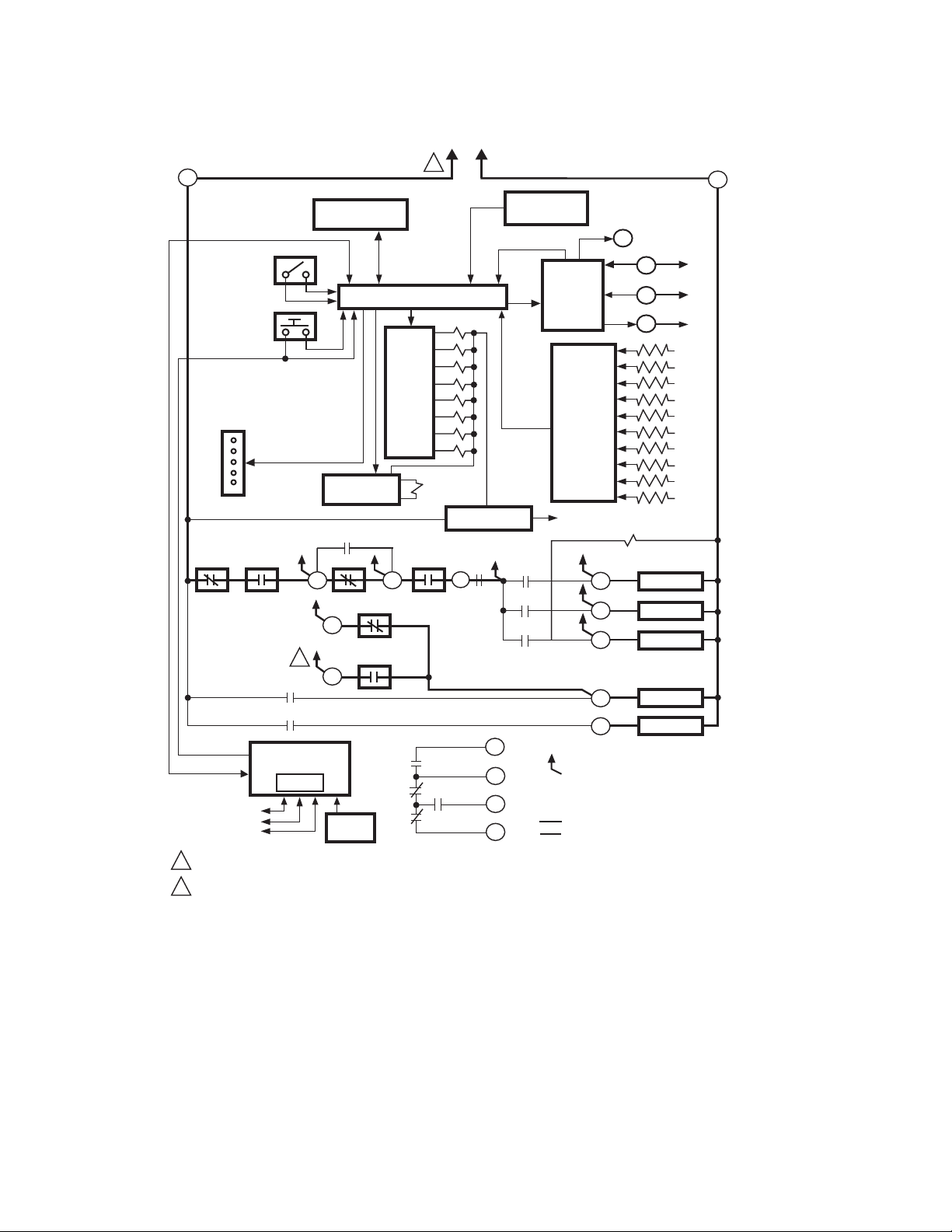
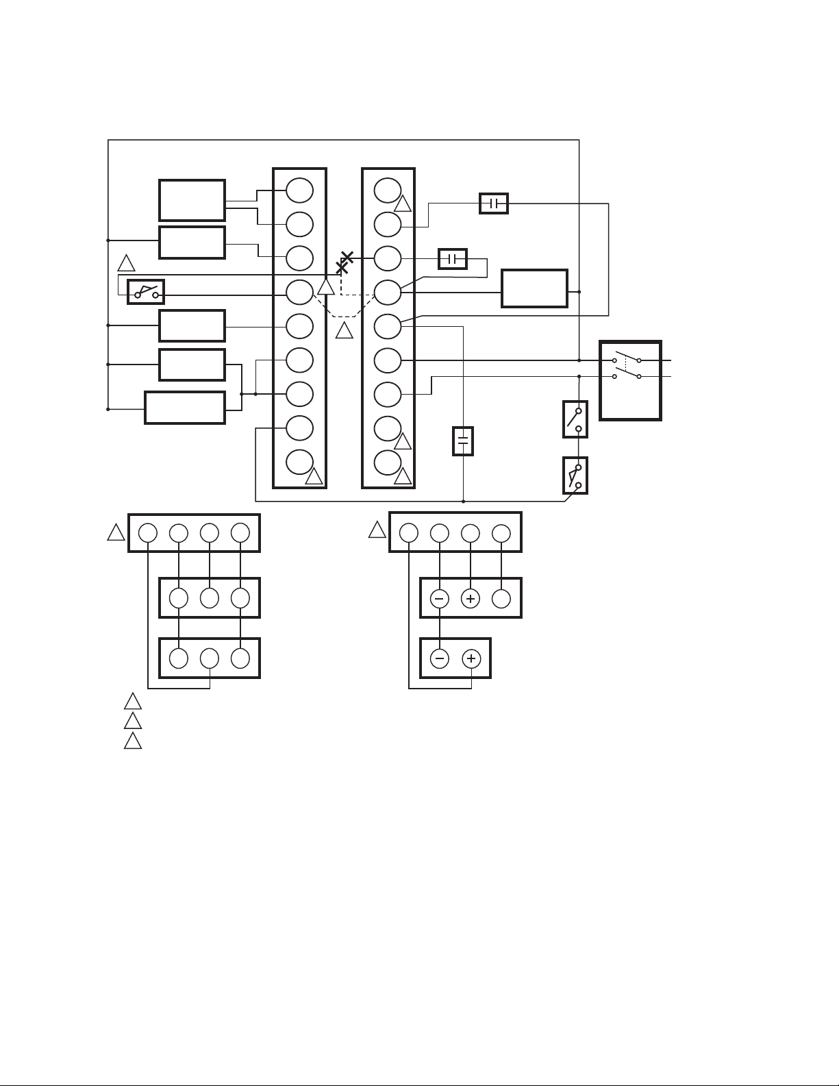
PROVIDE DISCONNECT MEANS AND OVERLOAD PROTECTION AS REQUIRED.
R7120D2000 DOES NOT HAVE A PURGE INTERLOCK
2
Fig. 2. Internal block diagram of the R7120D1002 and D2000.
66-1196EF—01 4
M32636
Page 5
R7120D BURNER CONTROL MODULES
LED
DISPLAY
BURNER
OPERATING
CONTROLS
AND
INTERLOCKS
FLAME
SIGNAL
FIRING
RATE
MOTOR
INITIATE
(INITIAL
POWERUP
ONLY)
POWER
STANDBY
POWER
SAFE START CHECK
PREPURGE
HOLD
00
DRIVE TO
HIGH FIRE
POWER
PII CLOSED
M
SWITCHING
R7120D1002, D2000
PREPURGE
00 00 10 25 00 15 20
TIMED
PREPURGE
POWER
PILOT
FLAME
MAIN
LIMITS AND BURNER CONTROLLER CLOSED
LOCKOUT INTERLOCKS CLOSED
HIGH FIRE SW.
8TO
10
TO
MOTOR ACTION
HOLD
DRIVE TO
LOW FIRE
POWER
PILOT
FLAME
MAIN
BURNER/BLOWER MOTOR
13
1
2
X
TO
00
3
PFEP
10 SEC.
(4 SEC. IF
JR1
CLIPPED
POWER
PILOT
FLAME
MAIN
10 SEC. IGN./PILOT
15 SEC. PILOT 6
LOW FIRE SW.
M D
10 12
MFEP
RUN
POWER
PILOT
FLAME
MAIN
ALARM ALARM ALARM ALARM
MAIN VALVE
3TO
TO
FLAME PROVING
TO
POWER
PILOT
FLAME
ALARM
M
5
3
TO
13
L1
P
10 11
MAIN
TO
POSTPURGE
7
1
1
POWER
TO
10 12
STANDBY
POWER
SSC
1
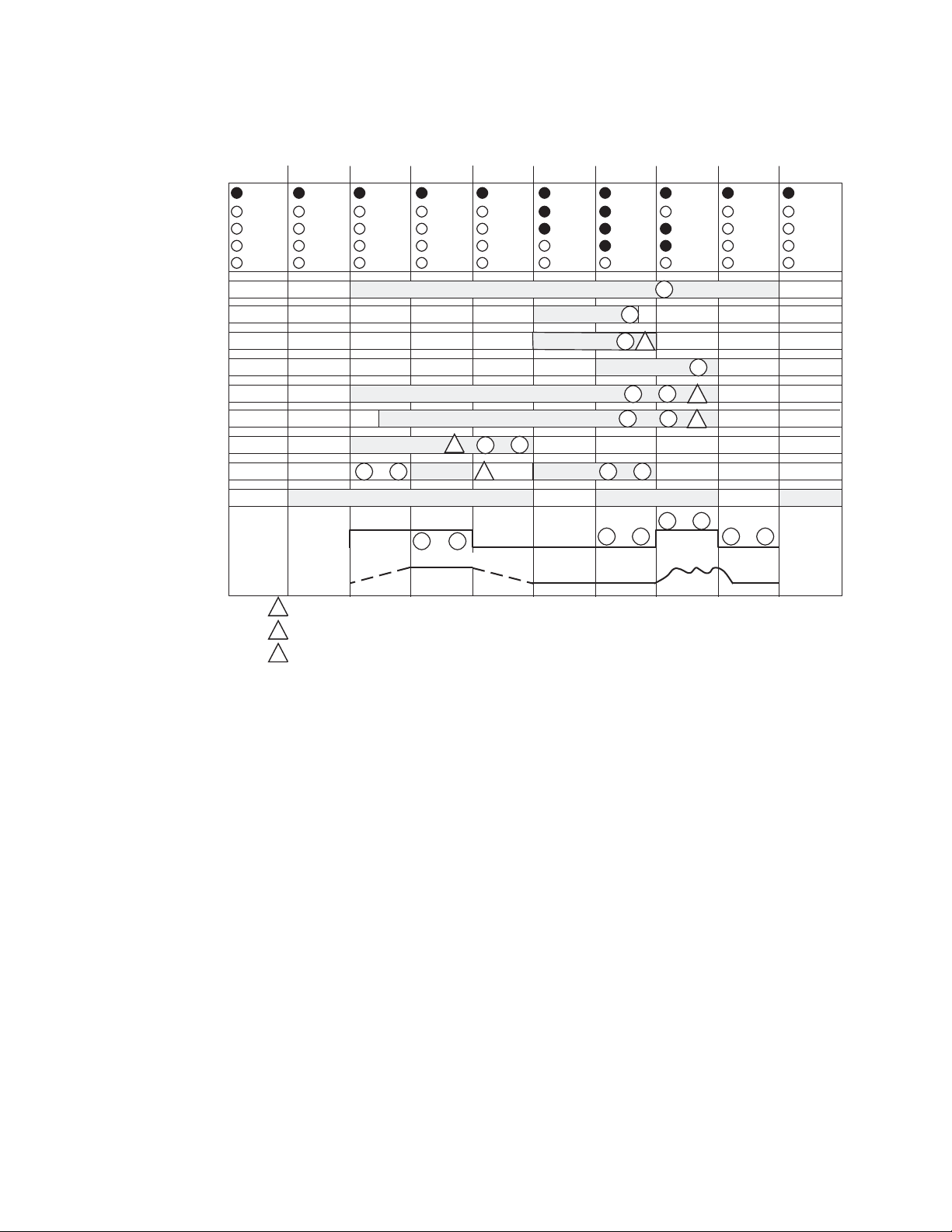
PII MEANS PRE-IGNITION INTERLOCK.
R7120D1002 ONLY
2
FOR R7120D2000
3
- CLIP JR2 FOR INTERRUPTED PILOT WITH 15 SECONDS MFEP
- CLIP JR2 AND ADD JUMPER BETWEEN TERMINAL 8 AND M FOR INTERRUPTED PILOT WITH 30 SECOND MFEP
Fig. 3. Operating sequence for R7120D1002.
M32637
5 66-1196EF—01
Page 6
R7120D BURNER CONTROL MODULES
FLAME
DETECTOR
(UV)
LOCKOUT
ALARM
2
PURGE INTERLOCK
D10/EP100 OR D20/EP200
TYPICAL WIRING
S2
S1
A
2
8
X
P
D
M
1
LOW FIRE START
INTERLOCK
RUNNING
INTERLOCK
BURNER/
BLOWER
MOTOR
MAIN FUEL
VALVE(S)
PILOT
VALVE(S)
IGNITION
TRANSFORMER
11 12 10 X
1
AUTO
LO COM HI
B
R
W
W R B
1
USED ONLY ON D10 OR EP100 SERIES PROGRAMMERS.
LOCATE THE PURGE INTERLOCK WIRE CONNECTION ON TERMINAL D, REMOVE AND CONNECT TO TERMINAL M.
2
R120D2000, JUMPER WIRE ADDED BETWEEN 8 AND M PROVIDES 30 MFEP ON TERMINAL 6, IF JR2 IS REMOVED.
3
7
6
5
13
12
1
FLAME MONITOR
TERMINALS
135 OHM
FIRING RATE
MOTOR
135 OHM
CONTROLLER
3
3
L2/N
L1/L
11
1
10
1
1
11 12 10
AUTO
LO
COM
VALVE
PROOF OF
CLOSURE
X
HI
F
4-20mA
CONTROLLER
BURNER
SWITCH
FLAME MONITOR
TERMINALS
4-20 mA
MOTOR
MASTER
SWITCH
LIMIT
OPERATING
SWITCHES
L2
L1
M32638
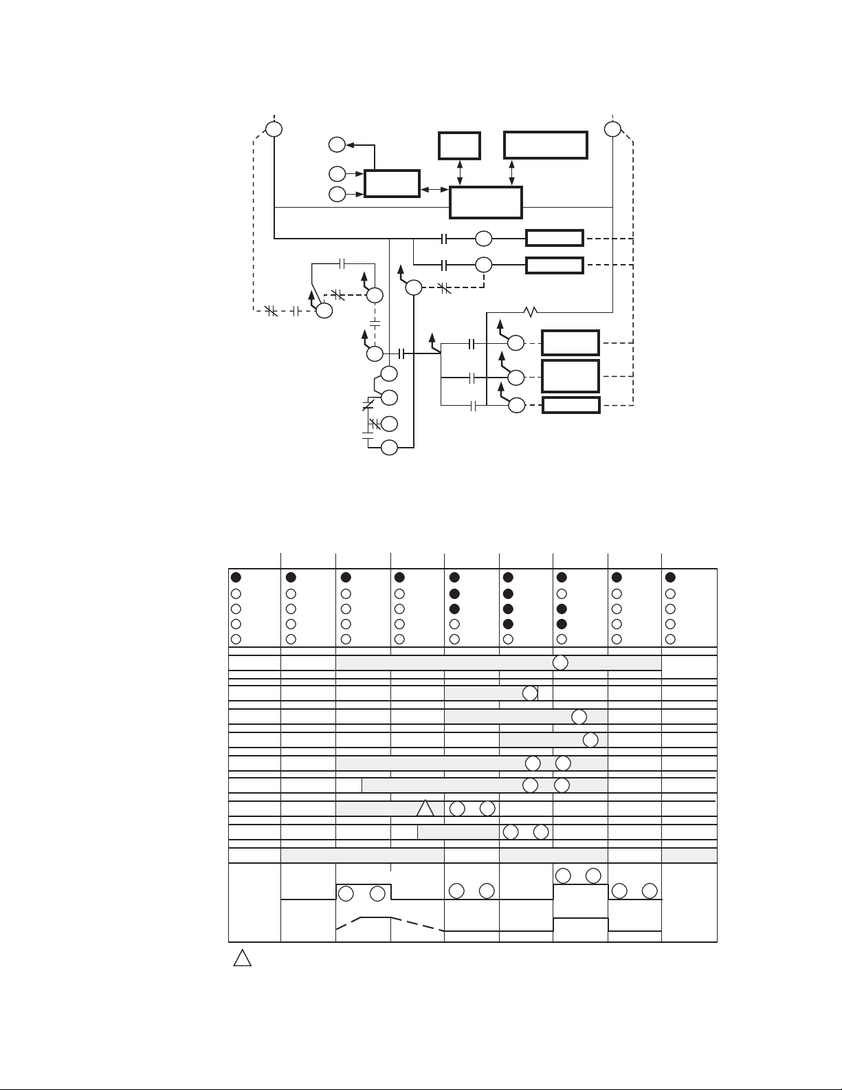
Fig. 4. Internal block diagram of the R7120D3007 with pre-ignition interlocks.
66-1196EF—01 6
Page 7
R7120D BURNER CONTROL MODULES
INTERNAL
ELECTRONICS
M32639
CONFIGURATION
JUMPERS
PURGE
TIMER
FLAME
AMPLIFIER
ALARM
BLOWER
INTERMITTENT
PILOT
1R1
3K1
6K1
A
M
6
MAIN VALVE
7
LF
D
F
G
17
L1
L1
L2
L2
15 SECOND
INTERMITTENT
PILOT VALVE
5
4K1
7K1
2K2
1K1
P
AIRFLOW
3
13
LIMITS
CONTROLLER
1R1
X
10
PRE-
IGNITION
11
8K2
9K1
12
9K2
LED
DISPLAY
BURNER
OPERATING
CONTROLS
AND
INTERLOCKS
FLAME
SIGNAL
DAMPER
MOTOR
Fig. 5. Internal block diagram of R7120D3007.
INITIATE
(INITIAL
POWERUP
ONLY)
POWER
1
STANDBY
PII MEANS PRE-IGNITION INTERLOCK.
00 00 10 25 00 15 20
TIMED
PREPURGE
POWER
LIMITS AND BURNER CONTROLLER CLOSED
SAFE START CHECK FLAME PROVING
R7120D SWITCHING
10 11
MOTOR ACTION
Fig. 6. Operating sequence for R7120D3007.
R7120D 3007
PREPURGE
HOLD
DRIVE TO
LOW FIRE
POWER
PILOT
FLAME
MAIN
BURNER/BLOWER MOTOR
PII CLOSED
TO
POWER
PILOT
FLAME
MAIN
RUNNING INTERLOCKS CLOSED
PFEP
10 SEC.
00
(4 SEC. IF
JR1
10 SEC. IGN./PILOT
INTERMITTENT PILOT VALVE
1
LOW FIRE SW.
7 66-1196EF—01
CLIPPED
POWER
PILOT
FLAME
MAIN
3
10 12
TO
13TO
MFEP
POWER
PILOT
FLAME
MAIN
ALARM ALARM ALARM ALARM
5
MAIN VALVE
L1
3
TO
M
TO
D
RUN
POWER
PILOT
FLAME
MAIN
ALARM
M
6
13
PTO
10 11
TO
POSTPURGE
7
POWER
10 12
TO
STANDBY
POWER
SSC
M32640
Page 8
R7120D BURNER CONTROL MODULES
L1
L2
S2
S1
A
8
7
6
5
13
12
X
P
D
M
3
L2/N
L1/L
11
10
FLAME
DETECTOR
(UV)
BURNER/
BLOWER
MOTOR
VALVE
PROOF OF
CLOSURE
LIMIT
OPERATING
SWITCHES
BURNER
SWITCH
RUNNING
INTERLOCK
LOW FIRE START
INTERLOCK
MASTER
SWITCH
LOCKOUT
ALARM
MAIN FUEL
VALVE(S)
INTERMITTENT
PILOT
VALVE(S)
INTERUPTED
PILOT
VALVE(S)
M32641
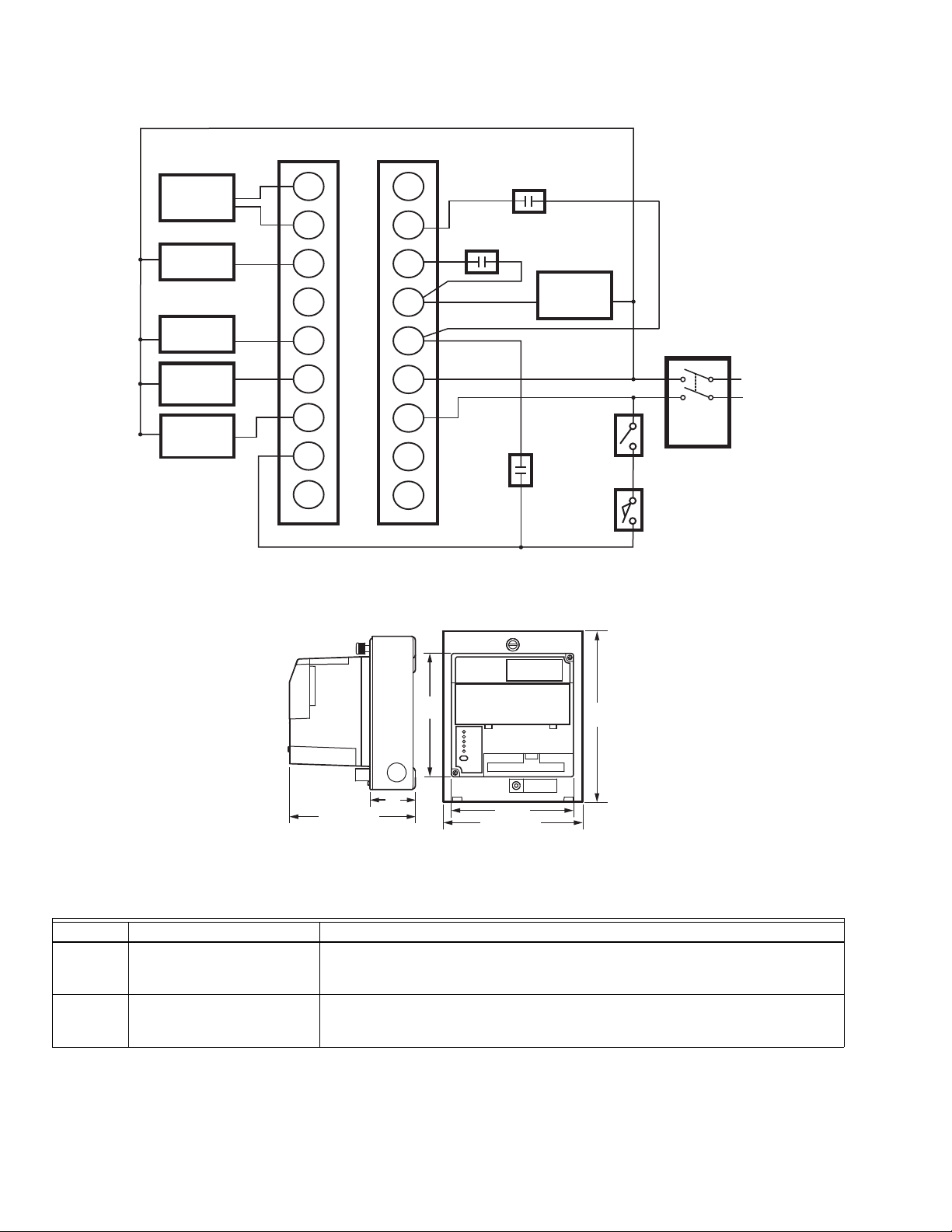
Fig. 7. Wiring hookup diagram for R7120D3007.
BURNER CONTROL
5
(127)
POWER
PILOT
FLAME
MAIN
ALARM
RESET
2
5-51/64 (147)
Fig. 8. Mounting dimensions of R7120D2000, R7120D1002, R7120D3007 Burner Control Module in in. (mm).
Terminal Typical Load Maximum Rating at 120 Vac, 60 Hz
5 or 6 Ignition
7 Main Fuel Valve(s) (solenoid/
66-1196EF—01 8
Transformer/Pilot
Valve/First Stage Fuel Valve
motorized/diaphragm) and
Vent Valve, if required
4.5A ignition and 50 VA pilot duty, or
2.5A ignition and 75 VA pilot duty.
250 VA pilot duty or 65 VA pilot duty in parallel with motorized valve(s) using a total of
1150 VA locked rotor (inrush), 460 VA to open, and 250 VA to hold or motorized valve(s)
using a total of 1500 VA locked rotor (inrush), 600 VA to open, and 250 VA to hold.
(51)
Table 2. Terminal Ratings.
5 (127)
5-45/64 (145)
7
(178)
M32698
Page 9
R7120D BURNER CONTROL MODULES
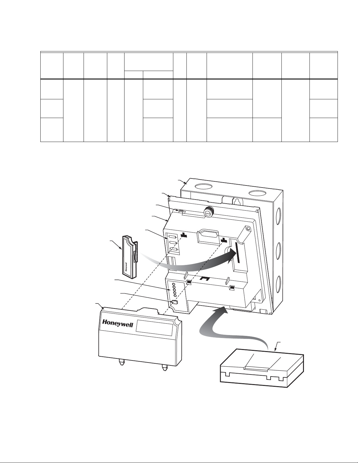
WIRING
SUBBASE
BURNER CONTROL
RELAY
MODULE
ADAPTER
PLATE
KEYBOARD
DISPLAY
MODULE
(OPTIONAL)
RESET
POWER
PILOT
FLAME
MAIN
ALARM
FLAME
AMPLIFIER
M32642
PURGE
TIMER
RESET
BUTTON
CONFIGURATION
JUMPERS
RUN/TEST
SWITCH
SEQUENCE
STATUS
LED PANEL
Table 3. Sequence Timing for Normal Operation.
Flame
Device Initiate Standby Purge
R7120D
10 sec. * ** 4 or 10
2000
Establishing
Period
10, 15
sec.
sec.a or
Post
Purge
Run
Timing Interlock Circuits
* 15 sec. Pre-Ignition,
Running, Low Fire
Firing
Rate
Circuit
4-wire
modulating
Energy
Approval
Saving
Pre-Purge
BodiesPilot Main
No UL/CSA
Modulating
intermittent.
R7120D
1002
10 or 15
sec
Pre-Ignition,
Lockout High and
FM/IRI
Modulating
Low Fire
R7120D
3007
10 sec. or
intermittent
Pre-Ignition,
Running, isolated
Low Fire.
2-wire
isolated
On-Off-On
UL/CSA
On-Off.
contacts
a
15 second MFEP with JR2 clipped, and 30 seconds with JR2 clipped and jumper from terminal M to terminal 8.
* STANDBY and RUN can be an infinite time period.
** PURGE will be determined by which ST7800A purge card is selected; 15 timings are available from 2 seconds to 30 minutes.
Code
Fig. 9. R7120D Relay Module, exploded view.
9 66-1196EF—01
Page 10

R7120D BURNER CONTROL MODULES
SAFETY SHUTDOWN
Safety Shutdown (Lockout) occurs if any of the following occur during the indicated period:
1. INITIATE Period:
a. Purge card is not installed or is removed.
b. Purge card is bad.
c. Configuration jumpers are changed (after 200 hours
of operation).
d. AC line power errors occur; see Operation section.
e. Four minute INITIATE period has been exceeded.
2. STANDBY Period:
a. Flame signal is present after 240 seconds.
b. Interlock check feature is enabled and the
Interlock String (including airflow switch) is closed
for 120 seconds with controller closed.
c. Ignition/pilot valve/intermittent pilot valve terminal is
energized.
d. Main valve terminal is energized.
e. Internal system fault occurs.
f. Purge card is not installed or is removed.
g. Purge card is bad.
3. PREPURGE Period:
a. Pre-Ignition Interlock opens anytime during PRE-
PURGE period (R7120D1002).
b. Flame signal is detected after first ten seconds
during PREPURGE (R7120D1002).
c. High Fire Switch fails to close within 4 minutes and
15 seconds after the firing rate motor is commanded
to drive to the high fire position at the start of PRE-
PURGE (R7120D1002).
d. Low Fire Switch fails to close within 4 minutes and
15 seconds after the firing rate motor is commanded
to drive to the low fire position at the end of PRE-
PURGE.
e. Running Interlock does not close within 30 seconds
(R7120D2000, R7120D3007).
f. Lockout Interlock does not close within 10 seconds
(R7120D1002).
g. Lockout Interlock opens during PREPURGE
(R7120D1002).
h. Ignition/pilot valve/intermittent pilot valve terminal is
energized.
i. Main valve terminal is energized.
j. Internal system fault occurs.
k. Purge card is removed.
l. Purge card is bad.
4. PILOT FLAME ESTABLISHING Period (PFEP):
a. Low Fire Switch opens.
b. Lockout Interlock opens (RM7140L).
c. Ignition/pilot valve/intermittent pilot valve terminal is
not energized.
d. Early spark termination terminal is energized after
five seconds.
e. No flame is present at the end of PFEP.
f. Main valve terminal is energized (R7120D2000,
R7120D3007).
g. Internal system fault occurs.
h. Purge card is removed.
i. Purge card is bad.
5. MAIN FLAME ESTABLISHING Period (MFEP):
a. Low Fire Switch Opens.
b. Lockout Interlock opens (R7120D1002).
c. Ignition/pilot valve/intermittent pilot valve terminal is
not energized.
d. Main valve terminal is not energized.
e. No flame is present at the end of MFEP.
f. Internal system fault occurs.
g. Purge card is removed.
h. Purge card is bad.
6. RUN Period:
a. No flame is present.
b. Lockout Interlock opens (R7120D1002).
c. Interrupted pilot valve terminal is energized
(R7120D2000, R7120D3007).
d. Main valve terminal is not energized.
e. Internal system fault occurs.
f. Purge card is removed.
g. Purge card is bad.
7. POSTPURGE Period:
a. Ignition/pilot valve/intermittent pilot valve terminal is
energized.
b. Main valve terminal is energized.
c. Internal system fault occurs.
d. Purge card is removed.
e. Purge card is bad.
OPERATION
Sequence of Operation
The R7120 has the following operating sequences; see Fig. 2
through 6 for internal diagrams, hookup drawings or operating
sequence charts. The R7120 LED provides positive visual
indication of the program sequence: POWER, PILOT, FLAME,
MAIN and ALARM.
Initiate
The R7120 enters the INITIATE sequence when the Relay
Module is powered. The R7120 can also enter the INITIATE
sequence if the Relay Module verifies voltage fluctuations of
+10/-15 percent or frequency fluctuations of ±10 percent
during any part of the operating sequence. The INITIATE
sequence lasts for ten seconds unless the voltage or
frequency tolerances are not met. When the tolerances are
not met, a hold condition is initiated for at least five seconds.
When the tolerances are met, the INITIATE sequence
restarts. If the condition is not corrected and the hold condition
exists for four minutes, the R7120 locks out. Causes for hold
conditions in the INITIATE sequence:
a. AC line dropout is detected.
b. AC line noise prevents a sufficient reading of the
line voltage inputs.
c. Low line voltage brownouts occur.
The INITIATE sequence also delays the burner motor starter
from being energized and de-energized from an intermittent
AC line input or control input.
Standby
The R7120 is ready to start an operating sequence when the
operating control determines a call for heat is present. The
burner switch, limits, operating control and all microcomputer
monitored circuits must be in the correct state for the R7120 to
continue into the PREPURGE sequence.
66-1196EF—01 10
Page 11

R7120D BURNER CONTROL MODULES
WARNING
Normal Start-Up Pre-Purge
The R7120 provides a pre-purge timing selectable with the
ST7800 Purge Timer cards, from two seconds to 30 minutes
with power applied and the operating control is indicating a
call for heat:
a. Running Interlocks, Pre-Ignition Interlocks, Burner
Switch, Run/Test Switch, Lockout Interlocks and all
microcomputer monitored circuits must be in the
correct operating state.
b. The blower motor output, terminal M, is powered to
start the PREPURGE sequence. The PREPURGE
timing for the R7120D1002 does not begin until the
High Fire Switch is closed.
NOTE: A jumpered High Fire Switch adds a 30-second hold
before the purge time starts.
c. The Pre-Ignition Interlock input must remain closed
throughout PREPURGE; otherwise, control returns to
the STANDBY state and holds (30 seconds) for the
R7120D2000, R7120D3007 or safety shutdown for the
R7120D1002 occurs.
d. The Lockout Interlock or Running Interlock inputs
(interlock circuit including Airflow Switch) must close
by ten seconds into PREPURGE; otherwise, a
recycle to the beginning of PREPURGE for the
R7120D2000, R7120D3007 will happen or a safety
shutdown for the R7120D1002 occurs.
e. When PREPURGE timing is complete, the firing rate
motor drives to the low fire position.
f. When the firing rate motor reaches low fire position,
the Low Fire Switch, terminal M to D, is energized to
enter the Ignition Trial state.
NOTE: A 30-second hold occurs for a jumpered Low Fire
Switch before the ignition trial period begins.
a. Terminal 7 is energized when the presence of flame is
verified at the end of the Pilot Flame Establishing
Period (PFEP).
b. Terminal 5 is turned off 10 seconds after terminal 7
is energized.
c. Terminal 6 action:
(1) R7120D1002: De-energized 15 seconds after
terminal 7 is energized.
(2) R7120D2000:
(a)Not turned off, or
(b)15 seconds after terminal 7 is energized and
JR2 is clipped, or
(c)30 seconds after terminal 7 is energized and
terminals 8 and M are jumpered and jumper
JR2 is clipped.
(3) R7120D3007: Remain energized as long as call
for heat is present.
Run
1.
Fifteen seconds after the main valve terminal 7 is
energized and flame is maintained, the R7120 goes to
Run.
2.
The firing rate motor releases to modulation
(R7120D1002,2000). Damper motor is energized
(R7120D3007).
3.
The R7120 is now in RUN and remains in RUN until the
controller input, terminal 13 opens, indicating that the
demand is satisfied or a limit opened.
Postpurge
The R7120 provides a 15-second POSTPURGE following the
completion of the RUN period (call for heat ends). The blower
motor output remains powered to drive all products of
combustion and any unburned fuel from the combustion
chamber. It also supplies combustion air to burn fuel being
purged from the fuel line downstream of the fuel shutoff valve.
Ignition Trials
1. Pilot Flame Establishing Period (PFEP):
a. With the firing rate motor at the low fire position:
(1) The pilot valve and ignition transformer,
terminals 5 and 6 are energized.
(a)The R7120D2000 has an interrupted or
intermittent pilot valve, terminal 6, depending
on the selection of configuration jumper 2.
(b) The R7120D1002 has a 15-second inter-
rupted pilot valve, terminal 6.
(c)The R7120D3007 has an intermittent pilot
valve, terminal 6.
NOTE: All of the R7120s have a ten-second interrupted pilot
valve/ignition, terminal 5.
(2) During PFEP, the Low Fire Switch must remain
closed. If it opens, a safety shutdown occurs.
(3) The Pre-Ignition Interlock input is ignored
throughout the Ignition Trial state.
b. Flame must be proven by the end of the 10-second
PFEP (four if JR1 is clipped) to allow the sequence
to continue. If flame is not proven by the end of
PFEP, a safety shutdown occurs.
2. Main Flame Establishing Period (MFEP):
1. The main fuel valve and intermittent pilot valve,
terminals 7 and 6, are de-energized and the firing rate
motor is commanded to the low fire position to begin the
POSTPURGE period.
2. After the 15-second POSTPURGE period is completed,
the blower motor (terminal 8) is de-energized and the
R7120 reenters Standby.
Run/Test Switch
Explosion Hazard.
Can cause serious injury or death.
Do not use the Run/Test switch during the Pilot Flame
Establishing Period for the R7120 when using Direct
Spark Function, because it turns on the main gas
valve, causing an accumulation of fuel in the burner.
The Run/Test Switch is located on the top side of the R7120,
see Fig. 1. The Run/Test Switch allows the burner sequence
to be altered as follows:
11 66-1196EF—01
Page 12

R7120D BURNER CONTROL MODULES
RUN/TEST SWITCH
NOTE: CONFIGURATION JUMPERS SHOWN FOR RM7800G/RM7840G.
SELECTABLE CONFIGURATION JUMPERS
M12301
1. In Pre-Purge Drive To High Fire Position
(R7120D1002), the Run/Test Switch, when placed in the
TEST position, holds in PREPURGE with the firing rate
motor in the High Fire position.
2. In the measured PREPURGE sequence, the Run/Test
Switch, when placed in the TEST position, causes the
PREPURGE timing to stop. The firing rate motor is in
the High Fire position.
3. In Pre-Purge Drive to Low Fire position, the Run/Test
Switch, when placed in the TEST position, holds the
burner sequence in PREPURGE with the firing rate
motor in the Low Fire position.
4.
In PFEP, the Run/Test Switch, when placed in the TEST
position, stops the timer during the first 8 seconds when a
10-second PFEP is selected or during the first 3 seconds
when a 4-second PFEP is selected, allowing pilot-turndown test and other burner adjustments to be made. This
activates a 15-second flameout timer that permits pilot
flame adjustment without nuisance safety shutdowns. The
Run/Test Switch is ignored during PFEP for the
R7120D1002 if terminals 5 and 7 or 7 and 6 are
jumpered.
5. During Run, the Run/Test Switch, when placed in the
TEST position, drives the firing rate motor to the Low
Fire position.
NOTE: When R7120 is switched to the Test mode, it stops and
holds at the next Run/Test Switch point in the operating
sequence. Make sure that the Run/Test Switch is in the
RUN position before leaving the installation.
SETTINGS AND ADJUSTMENTS
Selectable Site-Configurable Jumpers
The R7120 has site-configurable jumper options; see Fig. 10
and Table 4. If necessary, clip the site-configurable jumpers
with side cutters and remove the resistors from the Relay
Module.
Fig. 10. Selectable site-configurable jumpers.
Table 4. Site Configurable Jumper Options.
Jumper Number Description Intact Clipped R7120 Type
JR1 Pilot Flame Establishing
10 seconds 4 seconds All
Period (PFEP)
JR2
a
Pilot Valve
/Main Flame
Establishing Period (MFEP)
10 seconds/
Intermittent
15 or 30 seconds Interrupted
b
R7120D2000 only
JR3 Start-up Interlock Check Disabled Enabled All
a
Pilot Valve/First Stage Oil Valve (Valve/Start) terminal 5.
b
A 30 second MFEP can be accomplished by adding a jumper wire between terminals 8 and M.
SERVICE NOTE: Clipping and removing these site-configurable jumpers enhances the level of safety. Removal after 200 hours
of main valve operation will result in a hard lockout, Code 110.
66-1196EF—01 12
Page 13

R7120D BURNER CONTROL MODULES
WARNING
WARNING
SYSTEM CHECKOUT
Explosion Hazard.
Can cause serious injury or death.
Do not allow fuel to accumulate in the combustion
chamber for longer than a few seconds without igniting
to prevent danger of forming explosive mixture. Close
manual fuel shutoff valve(s) if flame is not burning at
end of specified time.
Electric Shock Hazard.
Can cause serious injury or death.
Use extreme care while testing system. Line voltage is
present on most terminal connections when power is on.
Open master switch before removing or installing R7120 Relay
Module or Keyboard Display Module connector.
Make sure all manual fuel shutoff valves are closed before
starting initial lightoff check and Pilot Turndown tests.
Do not put the system in service until you have satisfactorily
completed all applicable tests in this section and any others
recommended by the original equipment manufacturer.
Limit trial for pilot to ten seconds. Limit the attempt to light
main burner to two seconds after fuel reaches burner nozzle.
Do not exceed manufacturer nominal lightoff time.
IMPORTANT
1. If the system fails to perform properly, note the fault code,
fault message, equipment status, and sequence time on
the display. Then refer to the Troubleshooting section.
2. Repeat all required Checkout tests after all adjustments are made. All tests must be satisfied with the
flame detector(s) in their final position.
Equipment Recommended
S7800A Keyboard Display Module
Volt-ohmmeter (1M ohm/volt minimum sensitivity) with: 0-300
Vac capability. 0-6000 ohm capability. 0-10 Vdc capability.
Preliminary Inspection
Perform the following inspections to avoid common problems.
Make certain that:
1. Wiring connections are correct and all terminal screws
are tight.
2. Flame detector(s) is clean, installed and positioned
properly. Consult the applicable Instructions.
3. Combination of amplifier and flame detector(s) is
correctly used. See the amplifier specifications.
4. Plug-in amplifier and purge card are securely in place.
5. Burner is completely installed and ready to fire; consult
equipment manufacturer instructions. Fuel lines are
purged of air.
6. Combustion chamber and flues are clear of fuel and fuel
vapor.
7. Power is connected to the system disconnect switch
(master switch).
8. Lockout is reset (reset button) only if the Relay Module
is powered.
9. Run/Test Switch (if present) is in RUN position.
10. System is in STANDBY condition. STANDBY message
is displayed in the S7800 Keyboard Display Module.
11. All limits and interlocks are reset.
Flame Signal Measurement
See instructions provided with the amplifier.
Initial Lightoff Checks
Proved Pilot Systems
Perform this check on all installations that use a pilot. It should
immediately follow the preliminary inspection.
NOTE: Low fuel pressure limits, if used, could be open. If so,
bypass them with jumpers during this check.
1. Open the master switch.
2. Make sure that the manual main fuel shutoff valve(s) is
closed. Open the manual pilot shutoff valve. If the pilot
takeoff is downstream from the manual main fuel shutoff
valve(s), slightly open the manual main valve to supply
pilot gas flow. Make sure the main fuel is shut off just
upstream from the burner inlet, or disconnect power
from the automatic main fuel valve(s).
3.
Close the master switch and start the system with a call
for heat by raising the setpoint of the operating controller;
see the relay module sequence. The R7120 Relay Module should start the INITIATE sequence.
4. Let the sequence advance to PILOT IGN (status is dis-
played on the Keyboard Display Module, if used),
PILOT LED turns on, ignition spark should occur and
the pilot should light. If the pilot ignites, the FLAME LED
is energized. Go to step 7.
5. If the pilot flame is not established in ten seconds (four
seconds if configuration jumper JR1 is clipped), safety
shutdown occurs. Let the sequence complete its cycle.
6. Push the reset pushbutton, and let the system recycle
once. If the pilot still does not ignite, make the following
ignition/pilot adjustments:
a. Open the master switch and remove the Burner
Control Module from the subbase.
b. On the subbase, jumper 1 to the ignition terminal 4;
refer to the appropriate wiring diagram to determine
the proper terminal. Disconnect the leadwire to the
pilot valve if it is connected to the same terminal.
c. Close the master switch to energize only the ignition
transformer.
d. If the ignition spark is not strong and continuous,
open the master switch and adjust the ignition electrode spark gap setting to the manufacturer recom-
mendation.
e. Make sure the ignition electrodes are clean.
f. Close the master switch and observe the spark.
g. After a continuous spark is obtained, open the mas-
ter switch and add a jumper on the subbase from
terminal L1 power to the pilot terminal 3. Reconnect
the leadwire from the pilot valve if it was discon-
nected in step b.
h. Close the master switch to energize both the ignition
transformer and the pilot valve.
13 66-1196EF—01
Page 14

R7120D BURNER CONTROL MODULES
i. If the pilot does not ignite and if the ignition spark is
still continuous, adjust the pressure regulator until a
pilot is established.
j. When the pilot ignites properly and stays ignited,
open the master switch and remove the jumper(s)
from the terminals of the subbase.
k. Check for adequate bleeding of the fuel line.
l. Reinstall the Relay Module on the subbase, close the
master switch and then return to step 4.
7. When pilot ignites, measure the flame signal. If the pilot
flame signal is unsteady or approaching the 1.25 Vdc
minimum value, adjust the pilot flame size or detector
sighting to provide a maximum and steady flame signal.
8.
Recycle the system to recheck lightoff and pilot flame signal.
9. When the MAIN LED turns on, make sure the automatic
main fuel valve is open; then smoothly open the manual
main fuel shutoff valve(s) and watch for main burner
flame ignition. When the main burner flame is established, go to step 16.
10. If the main burner flame is not established within five
seconds or the normal lightoff time as specified by the
equipment manufacturer, close the manual main fuel
shutoff valve(s).
11. Recycle the system to recheck the lightoff and pilot
flame signal.
12.
Smoothly open the manual fuel shutoff valve(s) and try
lightoff again. (The first re-attempt may have been required
to purge the lines and bring sufficient fuel to the burner.)
13. If the main burner flame is not established within five
seconds or the normal lightoff time specified by the
equipment manufacturer, close the manual main fuel
shutoff valve(s). Check all burner adjustments.
14.
If the main burner flame is not established after two attempts:
a. Check for improper pilot size.
b. Check for excess combustion air at low fire.
c. Check for adequate low fire fuel flow.
d. Check for proper gas supply pressure.
e. Check for proper valve operation.
f. Check for proper pilot flame positioning.
15. Repeat steps 8 and 9 to establish the main burner
flame; then go to step 16.
16. With the sequence in RUN, make burner adjustments
for flame stability and Btu input rating.
17. Shut down the system by opening the burner switch or
by lowering the setpoint of the operating controller.
Make sure the main flame goes out. There may be a
delay due to gas trapped between the valve(s) and
burner. Make sure all automatic fuel valve(s) close.
18. Restart the system by closing the burner switch and/or
raising the setpoint of the operating controller. Observe
that the pilot is established during PILOT IGN and the
main burner flame is established during MAIN IGN
within the normal lightoff time.
19. Measure the flame signal. Continue to check for the
proper signal through the RUN period. Check the signal
at both High and Low Firing Rate positions and while
modulating, if applicable.
20. Run the burner through another sequence, observing
the flame signal for:
a. Pilot flame alone.
b. Pilot and main flame together.
c. Main flame alone (unless monitoring an intermittent
pilot). Also observe the time it takes to light the main
flame. Ignition of main flame should be smooth.
21. Make sure all readings are in the required ranges
before proceeding.
22. Return the system to normal operation.
NOTE: After completing these tests, open the master switch
and remove all test jumpers from the subbase terminals, limits/controls or switches.
Direct Spark Ignition Systems
This check applies to gas and oil burners not using a pilot. It
should immediately follow the preliminary inspection. Refer to
the appropriate sample block diagram of field wiring for the
ignition transformer and fuel valve(s) hookup.
NOTE: Low fuel pressure limits, if used, could be open. If so,
10. If the first stage burner flame is not established within
11. Check all burner adjustments.
12. Wait about three minutes. Close the master switch,
13. If the first stage burner flame is not established within
14. If necessary, repeat steps 11 through 13 to establish
15. When the first stage burner flame is established, the
16. Shut down the system by opening the burner switch or
17. If used, remove the bypass jumpers from the low fuel
18. If a second stage is used, make sure the automatic sec-
bypass them with jumpers during this check.
1. Open the master switch.
2. Complete the normal ready-to-fire checkout of the fuel
supply and equipment as recommended by the equipment manufacturer.
3. Close all manual main fuel shutoff valve(s). Check that
the automatic fuel valve(s) is closed. Make sure fuel is
not entering the combustion chamber.
4. Close the master switch and start the system with a call
for heat by raising the setpoint of the operating controller; see the relay module sequencing. The program
sequence should start the INITIATE sequence.
5.
Let the sequence advance through PREPURGE (if applicable). Ignition spark should occur when the PILOT LED turns
on. Listen for the click of the first stage fuel solenoid valve(s).
The Relay Module locks out and the ALARM LED turns on.
6. Let the Relay Module complete its cycle.
7. Open the manual fuel shutoff valve(s).
8. Push the reset button and the relay module recycles the
program sequence through PREPURGE (if applicable).
9. When the PILOT LED turns on, make sure that the first
stage burner flame is established. If it is, go to step 15.
four seconds, or within the normal lightoff time specified
by the equipment manufacturer, close the manual fuel
shutoff valve(s), and open the master switch.
open the manual fuel shutoff valve(s), and try to light off
the burner again. The first attempt may be required to
purge the lines and bring sufficient fuel to the burner.
four seconds, or within the normal lightoff time specified
by the equipment manufacturer, close the manual fuel
shutoff valve(s), and open the master switch.
the first stage burner flame. Then go to step 15.
sequence advances to RUN. Make burner adjustments
for flame stability and input rating. If a second stage is
used, go to step 18.
by lowering the setpoint of the operating controller.
Make sure the burner flame goes out and all automatic
fuel valves close.
pressure limit and subbase.
ond stage fuel valve(s) opened. Check the lightoff as
follows (or go to step 19):
a. Open the manual second stage fuel valve(s).
b. Restart the system by raising the setpoint of the
operating controller.
66-1196EF—01 14
Page 15

R7120D BURNER CONTROL MODULES
c. When the first stage burner flame is established,
watch for the automatic second stage fuel valve(s)
to open. Observe that the second stage lights off
properly.
d. Make burner adjustments for flame stability and
input rating.
e. Shut down the system by lowering the setpoint of
the operating controller. Make sure the burner flame
goes out and all automatic fuel valves close.
f. Go to step 19.
19.
Restart the system by closing the burner switch and/or raising the setpoint of the operating controller. Observe that the
burner flame is established during PILOT IGN, within the normal lightoff time specified by the equipment manufacturer.
20.
Measure the flame signal. Continue to check for the proper
signal through the RUN period. Check the signal at both
high and low firing rate positions and while modulating. Any
pulsating or unsteady readings require further attention.
21. Make sure all readings are in the required ranges
before proceeding.
NOTE: On completing these tests, open the master switch
and remove all test jumpers from the subbase terminals, limits/controls or switches.
22. Return the system to normal operation.
Pilot Turndown Test (All Installations Using a Pilot)
Perform this check on all installations that use a pilot. The
purpose of this test is to verify that the main burner can be lit
by the smallest pilot flame that can hold in the flame amplifier
and energize the FLAME LED. Clean the flame detector(s) to
make sure that it detects the smallest acceptable pilot flame.
If using AMPLI-CHECK™ or self-checking amplifier and
1M ohm/voltmeter, the flame signal fluctuates every time the
amplifier does a self-check or a shutter check.
NOTE: Low fuel pressure limits, if used, could be open. If so,
bypass them with jumpers during this test.
1. Open the master switch.
2. Close the manual main fuel shutoff valve(s).
3. Connect a manometer (or pressure gauge) to measure
pilot gas pressure during the turndown test.
4. Open the manual pilot shutoff valve(s).
5. Close the master switch and start the system with a call
for heat. Raise the setpoint of the operating controller.
The R7120D sequence should start, and PREPURGE
should begin.
6. After the PILOT LED turns on in interrupted pilot appli-
cations, set the Run/Test Switch to the TEST position to
stop the sequence. The FLAME LED comes on when
the pilot ignites.
NOTE: If the sequence does not stop, reset the system and
make sure you set the Run/Test Switch to TEST
within the first eight seconds of the PILOT IGN
sequence.
IMPORTANT
You have 0.8 second or three seconds, depending
on PFEP selected, to position the Run/Test Switch to
the TEST position to stop the sequence after the
start of the PILOT IGN period.
7. Turn down the pilot pressure very slowly, reading the
manometer (or pressure gauge) as it drops. Stop
instantly when the FLAME LED goes out. Note the pressure. The pilot is at the minimum turndown position.
Immediately turn up the pilot pressure until the FLAME
LED comes on again or the flame signal increases to
1.25 Vdc.
NOTE: If there is no flame for 15 seconds with the Run/Test
switch in the TEST position, the relay module locks out.
8. Repeat step 7 to verify the pilot gas pressure reading at
the exact point the FLAME LED light goes out.
9. Increase the pilot pressure immediately until the FLAME
LED comes on, and then turn it down slowly to obtain a
pressure reading just above the dropout point or until
the flame signal increases to 1.25 Vdc.
10. Set the Run/Test Switch in the RUN position (if used)
and let the sequence proceed. When the MAIN LED
turns on, make sure the automatic main fuel valve(s)
opens; then smoothly open the manual main fuel shutoff
valve(s) (or any other manually-opened safety shutoff
valve(s), if used) and watch for main burner ignition. If
the main burner flame is established, go to step 18.
NOTE: This step requires two people, one to open the man-
ual valve(s) and one to watch for ignition.
11. If the main burner flame is not established within five
seconds, or within the normal lightoff time specified by
the equipment manufacturer, close the manual main
fuel shutoff valve(s) and open the master switch. If the
lightoff is rough, the pilot flame size is too small.
12. Close the master switch to recycle the burner and stop
the sequence in the PILOT period by using the
Run/Test Switch.
13. Increase the pilot flame size by increasing its fuel flow
until a smooth main flame is accomplished.
14. Reposition the flame scanner sight tube or use orifices
until the pilot flame signal voltage is in the range of 1.25
to 1.50 Vdc.
15. When the main burner lights reliably with the pilot at
turndown, disconnect the manometer (or pressure
gauge) and turn up the pilot gas flow to that recommended by the equipment manufacturer.
16. If used, remove the bypass jumpers from the subbase
terminals, limits/controls, or switches.
17. Run the system through another cycle to check for
normal operation.
18. Return the system to normal operation.
Ignition Interference Test (All Flame Rods)
Ignition interference can subtract from (decrease) or add to
(increase) the flame signal. If it decreases the flame signal
enough, it causes a safety shutdown. If it increases the flame
signal, it could cause the FLAME LED to come on when the
true flame signal is below the minimum acceptable value.
Start the burner and measure the flame signal with both
ignition and pilot (or main burner) on, and then with only the
pilot (or main burner) on. Any significant difference (greater
than 0.5 Vdc) indicates ignition interference.
15 66-1196EF—01
Page 16

R7120D BURNER CONTROL MODULES
To Eliminate Ignition Interference
1. Make sure there is enough ground area.
2. Be sure the ignition electrode and the flame rod are on
opposite sides of the ground area.
3. Check for correct spacing on the ignition electrode:
a. 6000V systems—1/16 to 3/32 in. (1.6 to 2.4 mm).
b. 10,000V systems—1/8 in. (3.2 mm).
4. Make sure the leadwires from the flame rod and ignition
electrode are not too close together.
5. Replace any deteriorated leadwires.
6. If the problem cannot be eliminated, consider changing
the system to an ultraviolet flame detection system.
Hot Refractory Saturation Test (All Infrared Detectors)
Start the burner and monitor the flame signal during the warmup period. A decrease in signal strength as the refractory
heats up indicates hot refractory saturation. If saturation is
extreme, the flame signal drops below 1.25 Vdc and the
system shuts down as though a flame failure occurred.
If hot refractory saturation occurs, the condition must be corrected.
Add an orifice plate in front of the cell to restrict the viewing area,
lengthen the sight pipe or decrease the pipe size (diameter).
Continue adjustments until hot refractory saturation is eliminated.
Hot Refractory Hold-in Test (Rectifying Photocell, Infrared Detectors, Ultraviolet Detectors)
This condition can delay response to flame failure and also
can prevent a system restart if hot refractory is detected.
Infrared (lead sulfide) detectors can respond to infrared rays
emitted by a hot refractory, even when the refractory has
visibly ceased to glow. Infrared radiation from a hot refractory
is steady, but radiation from a flame has a flickering
characteristic. The infrared detection system responds only to
flickering infrared radiation; it can reject a steady signal from
hot refractory. The refractory steady signal can be made to
fluctuate if it is reflected, bent or blocked by smoke or fuel mist
within the combustion chamber. Be careful when applying an
infrared system to verify its response to flame only.
The ultraviolet detector can respond to hot refractory above
2300°F (1371°C).
1. Operate the burner until the refractory reaches its maxi-
mum temperature (infrared only). If the installation has a
multi-fuel burner, burn the heavier fuel that is most likely
to reflect, bend or obscure the hot refractory steady
infrared radiation.
2.
When the maximum refractory temperature is reached,
close all manual fuel shutoff valves, or open the electrical
circuits of all automatic fuel valves.
3. Visually observe when the burner flame or FLAME LED
goes out. If this takes more than three seconds, the
infrared detector is sensing hot refractory.
4. Immediately terminate the firing cycle. Lower the set-
point to the operating controller, or set the Fuel Selector
Switch to OFF. Do not open the master switch.
NOTE: Some burners continue to purge oil lines between
the valves and nozzles even though the fuel valves
are closed. Terminating the firing cycle (instead of
opening the master switch) allows purging the combustion chamber. This reduces a buildup of fuel
vapors in the combustion chamber caused by oil line
purging.
5. If the detector is sensing hot refractory, correct the con-
dition by one or more of the following procedures:
a. Add an orifice plate in front of the cell to restrict the
viewing area of the detector.
b. Resight the detector at a cooler, more distant part of
the combustion chamber. Make sure the detector
properly sights the flame.
c. Try lengthening the sight pipe or decreasing the
pipe size (diameter).
For details, refer to the detector Instructions and the
equipment Operating Manual. Continue adjustments until hot
refractory hold-in is eliminated.
Ignition Spark Response Test (All Ultraviolet Detectors)
Test to make certain that the ignition spark is not actuating the
FLAME LED:
Close the pilot and main burner manual fuel shut-off valve(s).
1.
2. Start the burner and use the Run/Test Switch (if avail-
able) to stop the sequence in the PILOT IGN period.
Ignition spark should occur, but the flame signal should
not be more than 0.5 Vdc.
3.
If the flame signal is higher than 0.5 Vdc and the FLAME
LED does come on, consult the equipment operating
manual and resight the detector farther out from the
spark, or away from possible reflection. It may be necessary to construct a barrier to block the ignition spark from
the detector view. Continue adjustments until the flame
signal due to ignition spark is less than 0.5 Vdc.
NOTE: The Honeywell Q624A and Q652B Solid State Spark
Generators prevent detection of ignition spark when
properly applied with C7027, C7035, C7044 or
C7061 Ultraviolet Flame Detectors. The Q624A and
Q652B are only for use with gas pilots.
Response To Other Ultraviolet Sources
Some sources of artificial light (such as incandescent or
fluorescent bulbs, mercury sodium vapor lamps and daylight)
produce small amounts of ultraviolet radiation. Under certain
conditions, an ultraviolet detector responds to these sources as
if it is sensing a flame. To check for proper detector operation,
check the Flame Failure Response Time (FFRT) and conduct
Safety Shutdown Tests under all operating conditions.
Flame Signal With Hot Combustion Chamber (All Installations)
1. With all initial start-up tests and burner adjustments
completed, operate the burner until the combustion
chamber is at the maximum expected temperature.
2.
Observe the equipment manufacturer warm-up instructions.
3. Recycle the burner under these hot conditions and
measure the flame signal. Check the pilot alone, the
main burner flame alone, and both together (unless
monitoring only the pilot flame when using an intermittent pilot, or only the main burner flame when using
DSI). Check the signal at both High and Low Firing Rate
positions and while modulating, if applicable.
66-1196EF—01 16
Page 17

R7120D BURNER CONTROL MODULES
Check the FFRT of the flame amplifier and relay module.
4. Lower the setpoint of the operating controller and
observe the time it takes for the burner flame to go out.
This should be within the maximum FFRT.
5. If the flame signal is too low or unsteady, check the
flame detector temperature. Relocate the detector if the
temperature is too high.
6. If necessary, realign the sighting to obtain the proper
signal and response time.
7. If the response time is still too slow, replace the Plug-In
Flame Signal Amplifier.
8. If the detector is relocated or resighted, or the amplifier
is replaced, repeat all required Checkout tests.
Safety Shutdown Tests (All Installations)
Perform these tests at the end of Checkout, after all other
tests are completed. If used, the external alarm should turn
on. Press the RESET pushbutton on the relay module to
restart the system.
1. Detection of flame 240 seconds after entry to STANDBY
from RUN, fault code 9. Detection of flame from 10 seconds up to 30 seconds into PREPURGE time.
a. Simulate a flame to cause the flame signal voltage
level to be at least 1.25 Vdc for 40 seconds after
entry to STANDBY from RUN and also simulate a
flame signal for 10 seconds to 30 seconds for PREPURGE.
b. *Flame Detected* fault is displayed on the Keyboard
Display Module. Fault code 9 or 15 or 18 is displayed
to denote the fault.
c. Safety shutdown occurs.
2. Failure to ignite pilot.
a. Close pilot and main fuel manual shutoff valve(s).
b. Cycle burner on.
c. Automatic pilot valve(s) should be energized but the
pilot cannot ignite.
d. *Pilot Flame Fail* fault is displayed on the Keyboard
Display Module. Fault code 28 is displayed four or ten
seconds, depending on the jumper configuration
selection for Pilot Flame Establishing Period (PFEP)
after the pilot valve(s) is energized to denote the fault.
e. Safety shutdown occurs.
3. Failure to ignite main (only interrupted pilot application).
a. Open the manual pilot valve(s); leave the main fuel
manual shutoff valve(s) closed.
b. Depress the RESET button.
c. Start the system.
d. The pilot should ignite and the flame signal should
be at least 1.25 Vdc but the main burner cannot light.
e. The flame signal should drop below 1.25 Vdc within
the FFRT of the amplifier and the relay module after
the interrupted pilot goes out.
f. *Main Flame Ign.* fault is displayed on the Key-
board Display Module. Fault code 19 is displayed to
denote the fault.
g. Safety shutdown occurs.
4. Loss of flame during RUN.
a. Open the main fuel manual shutoff valve(s) and
open manual pilot shutoff valve(s).
b. Depress the RESET button.
c. Start the system. Start-up should be normal and the
main burner should light normally.
d. After the sequence is in the normal RUN period for at
least ten seconds with the main burner firing, close
the manual main fuel shutoff valve(s) to extinguish
the main burner flame. (On intermittent pilot applica-
tions, also, close the pilot manual shutoff valve.)
e. The flame signal should drop below 1.25 Vdc within
the FFRT of the amplifier and the relay module after
the main flame and/or pilot goes out.
f. *Main Flame Fail* fault is displayed on the Keyboard
Display Module. Fault code 17 is displayed to
denote the fault.
g. Safety shutdown occurs, or will recycle if jumper JR2
is intact, then lock out on failure to light the pilot.)
IMPORTANT
If the relay module fails to shut down on any of these
tests, take corrective action; refer to Troubleshooting
and the relay module diagnostics and return to the
beginning of all Checkout tests.
When all Checkout tests are completed, reset all switches to
the original status.
17 66-1196EF—01
Page 18

R7120D BURNER CONTROL MODULES
66-1196EF—01 18
Page 19

R7120D BURNER CONTROL MODULES
19 66-1196EF—01
Page 20

R7120D BURNER CONTROL MODULES
Automation and Control Solutions
Honeywell International Inc.
1985 Douglas Drive North
Golden Valley, MN 55422
customer.honeywell.com
® U.S. Registered Trademark
© 2011 Honeywell International Inc.
66-1196EF—01 M.S. 07-11
Printed in U.S.A.
Page 21

Put Bar Code Here
Modules de régulation de brûleur
R7120D
NOTICE D'INSTALLATION
APPLICATION
Le R7120D est un dispositif de rechange fonctionnel
enfichable commandé par microprocesseur pour le système
Fireye série D et E utilisant la plaque de raccordement
existante. Le R7120D est un régulateur intégré pour brûleurs
à allumage automatique au gaz, au mazout ou au gaz et
mazout combinés dans les applications marche-arrêt ou à
brûleur unique à modulation. Le système R7120D comprend
un module de relais, un amplificateur et une carte de
balayage. Les options incluent un module à clavier et afficheur
(KDM), un module Data ControlBus™, un module ModBus™
et un système d’affichage à distance. Voir le guide des
références des contrôleurs de programmation Honeywell
(réf. 70-8313, disponible sur le site Web
www.customer.honeywell.com) pour les pièces correctes et la
sélection des caractéristiques.
Les fonctions fournies par le R7120D incluent la mise en
séquence automatique du brûleur, la surveillance de la
flamme, l'indication de l'état du système, les diagnostics du
système ou l'autodiagnostic et le dépannage.
Modèles R7120D disponibles :
R7120D1002 pour Fireye D10 ou E1XX
R7120D2000 pour Fireye D20 ou E2XX
R7120D3007 pour Fireye D30 ou E3XX
CARACTÉRISTIQUES TECHNIQUES
Caractéristiques électriques (voir tableau 2) :
Tension et fréquence :
120 V c.a. (+10/-15 %), 50/60 Hz (± 10 %).
Dissipation d’énergie : 10 W maximum.
Charge connectée totale maximum : 2000 VA.
Fusible pour charge connectée totale : 15 A à fusion rapide,
type SC ou équivalent.
Caractéristiques environnementales :
Température ambiante :
Fonctionnement : -40 °F à 140 °F (-40 °C à 60 °C).
Stockage : -40 °F à 150 °F (-40 °C à 66 °C).
Humidité : 85 % d’humidité relative en continu, sans
condensation.
Vibration : 0,5 G environnement.
Homologations :
Composant répertorié cULus : fichier n° MP268; Guide n°
MCCZ.
Federal Communications Commission Émissions Section
15 Classe B.
Éléments requis pour le fonctionnement (à commander
séparément) :
La sélection est basée sur la configuration du contrôleur
Fireye remplacé :
Temporisateur de balayage
Amplificateur de flamme
Détecteur de flamme
Table des matières
Application ........................................................................1
Caractéristiques Techniques ............................................ 1
Installation ........................................................................ 2
Instructions Générales .....................................................2
Coupure De Sécurité ........................................................ 11
Fonctionnement ...............................................................11
Réglages Et Ajustements .................................................13
Vérification Du Système ...................................................14
Composants en option :
Module afficheur et clavier S7800A1001
Module Modbus S7810M1003
Couvercle S7820A1007 pour réarmement à distance
66-1196EF-01
Page 22

MODULES DE RÉGULATION DE BRÛLEUR R7120D
AVERTISSEMENT
AVERTISSEMENT
AVERTISSEMENT
MISE EN GARDE
AVERTISSEMENT
INSTALLATION
Risque d’incendie ou d’explosion.
Peut causer des dégâts et des blessures graves,
voire mortelles.
Respecter toutes les exigences de sécurité
applicables lors de l’installation d’un régulateur sur un
brûleur pour éviter les blessures graves ou mortelles.
Risque de choc électrique.
Peut causer des dégâts et des blessures graves,
voire mortelles.
Débrancher l’alimentation avant de commencer
l’installation. Il peut être nécessaire d'effectuer plus
d'un débranchement.
Lors de l’installation de ce produit...
1. Lire attentivement ces instructions. Le non-respect des
instructions peut endommager le produit ou provoquer
une situation dangereuse.
2. L’installateur doit être un technicien formé, expérimenté
et qualifié en matière de surveillance de flamme.
3. Une fois l’installation terminée, effectuer la vérification
du système indiquée dans cette notice.
IMPORTANT
1. Deux détecteurs de flamme peuvent être connectés
en parallèle à l’exception des détecteurs de flamme
C7915, C7927, C7961 et C7952.
2. Cet équipement génère, utilise et peut émettre de
l’énergie de radiofréquence, et s'il n'est pas installé
et utilisé conformément aux instructions, peut causer
des interférences aux communications radio. Il a été
testé et est conforme aux limites des dispositifs
numériques de classe B, conformément à la partie
15 du règlement de la FCC.
3. Cet appareil numérique ne dépasse pas les limites
de classe B relatives au bruit radioélectrique des
appareils numériques indiquées dans le règlement
sur le brouillage radioélectrique du ministère des
Communications canadien.
Veiller à bien choisir les cavaliers de configuration avant de
lancer le fonctionnement du brûleur.
Risque de choc électrique.
Peut endommager ou causer une défaillance de
l’équipement.
Ne pas effectuer de test diélectrique lorsque le module
de relais est installé. Le suppresseur de surtension
interne peut tomber en panne, causant l’échec du test
diélectrique par le module du relais et la destruction de
la protection contre la foudre et les hautes intensités.
Risque de choc électrique.
Peut causer des dégâts et des blessures graves,
voire mortelles.
Débrancher l’alimentation avant de commencer
l’installation. Il peut être nécessaire d'effectuer plus
d'un débranchement.
1. Débrancher l’alimentation électrique au sectionneur
principal avant de commencer l’installation pour
empêcher les chocs électriques et les dégâts matériels.
Il peut être nécessaire d'effectuer plus d'un
débranchement.
2. Desserrer la vis de montage pour retirer le contrôleur
Fireye de la plaque de raccordement.
3. Vérifier tout le câblage de la plaque de raccordement et
s’assurer que les connexions sont correctes, les vis de
bornes serrées, les fils corrects et les techniques de
câblage adéquates. Remplacer tous les fils
endommagés ou de taille incorrecte.
4. Remplacer les contrôleurs défectueux, les limiteurs, les
dispositifs de verrouillage, les actionneurs, les vannes,
les transformateurs, les moteurs et les autres
dispositifs, selon le besoin. Ne pas contourner les
limiteurs et les dispositifs de verrouillage.
5. S’assurer que les charges ne dépassent pas les
caractéristiques nominales des bornes. Consulter
l’étiquette du R7120D.
6. Voir le tableau 1 pour les pratiques de mise à la terre
recommandées. Le R7120D est un contrôleur à
microprocesseur et une bonne mise à la terre est
importante pour assurer un fonctionnement sûr et fiable.
INSTRUCTIONS GÉNÉRALES
Risque d’incendie ou d’explosion.
Peut causer des dégâts et des blessures graves,
voire mortelles.
Fermer toutes les vannes de combustible manuelles
avant de procéder au remplacement.
Tester le système avec grande prudence. Une tension de
secteur est présente sur la plupart des connexions de bornes
lorsque le système est alimenté.
66-1196EF—01 2
Installation des détecteurs de flamme Honeywell
1. Les détecteurs de flamme à infrarouge et ultraviolets
Fireye NE DOIVENT PAS être utilisés avec le R7120D.
2. Consulter les modes d’emploi Honeywell pour
l’installation correcte du détecteur de flamme.
REMARQUE : le fil de la borne F Honeywell est
connecté à la borne S1 de la plaque de raccordement
Fireye. Le fil de la borne G est connecté à la borne S2
du Fireye.
3. Applications nécessitant des détecteurs de flamme à
obturateur : Connecter un des fils de l’obturateur à la vis
de borne au dos du R7120D. Voir la Fig. 1.
Page 23

AVERTISSEMENT
VIS DE BORNE
Fig. 1. Vis de borne du R7120D.
MF32654
Remplacement des dispositifs Fireye D10 ou E1XX par le R7120D
1. Repérer le fil situé sur la borne D et connecté à
l’interrupteur haute combustion (ou taux de balayage).
2. Retirer ce fil et le brancher à la borne M.
MODULES DE RÉGULATION DE BRÛLEUR R7120D
sorte qu’il n’interfère pas avec l’enclenchement des
bornes de la plaque de raccordement dans la base du
régulateur.
2. Vérifier les languettes électriques au dos du châssis. Si
elles ne sont pas bien positionnées, les repositionner
avec les doigts pour bien les aligner.
3. Placer le contrôleur R7120D sur les languettes de
montage de la plaque de raccordement existante et
faire pivoter le contrôleur en place. Si un fil d’obturateur
a été installé sur le détecteur de flamme Honeywell,
s'assurer qu'il n'est pas pincé. Consulter la Fig. 8 pour
les informations de montage.
4. Appuyer doucement le contrôleur sur la plaque de
raccordement pour engager les fiches de bornes et fixer
avec la vis de montage captive en haut et au milieu du
boîtier du contrôleur R7120D.
5. Serrer suffisamment les vis de montage pour asseoir le
R7120 sur la plaque de raccordement SANS TROP
SERRER.
6. Si l’installation se fait dans un tableau de distribution,
s’assurer qu’il y a un dégagement suffisant derrière la
porte fermée du tableau pour qu’il n’y ait pas
d’interférence avec le R7120.
Montage des autres composants du système
Consulter la Fig. 9 pour la vue éclatée de l’installation ou la
notice technique applicable pour le montage des autres
composants du système.
Installation du module de relais R7120D
1. S’assurer qu’aucun câblage de plaque de raccordement
ne se projette au-delà des borniers. Acheminer le
câblage contre le dos de la plaque de raccordement de
Tableau 1. Pratiques de mise à la masse recommandées.
Type de mise à la terre Pratique recommandée
Prise de terre (plaque de
raccordement et module de relais).
Signal à la terre (module afficheur à
clavier, module Data ControlBus™,
module Modbus).
1. Utiliser pour fournir une connexion entre la plaque de raccordement et le tableau de
commande de l’équipement. La prise de terre doit pouvoir fournir un courant
suffisant pour griller le fusible à fusion rapide de type SC de 15 A (ou le disjoncteur)
en cas de court-circuit interne.
2. Utiliser des brides ou des supports larges pour fournir des conducteurs de terre de
longueur minimum et de surface maximum. Si un fil est requis, utiliser un fil de
cuivre de calibre 14 (AWG).
3. S’assurer que les joints à serrage mécanique le long de la mise à la terre sont
exempts de revêtements non conducteurs et protégés contre la corrosion sur les
surfaces de contact.
Utiliser la gaine du fil de signal pour mettre le dispositif à la terre à la borne 3(c) de terre
de signal pour chaque dispositif. Connecter la gaine aux deux extrémités de la guirlande
à la prise de terre.
Risque d’incendie ou d’explosion.
Peut causer des dégâts et des blessures graves,
voire mortelles.
Respecter toutes les exigences de sécurité
applicables lors de l’installation d’un régulateur sur un
brûleur pour éviter les blessures graves ou mortelles.
3 66-1196EF—01
Page 24

MODULES DE RÉGULATION DE BRÛLEUR R7120D
CAVALIERS DE
CONFIGURATION
MICRO-ORDINATEUR
BOUTON
POUSSOIR DE
RÉARMEMENT
INTERRUPTEUR
DE TEST/
FONCTIONNEMENT
DEL D’ÉTAT
CARTE DE TEMPORISATEUR
DE BALAYAGE ENFICHABLE
CIRCUIT DE RELAIS
DE SÉCURITÉ
ALIMENTATION
MODULE AFFICHEUR
ET CLAVIER
HAUTE COMBUSTION
COMMUN
MODULATION
COMBUSTION
BASSE
INTERRUPTEUR
VERROUILLAGE BALAYAGE
AMPLIFICATEUR
DE FLAMME
ENFICHABLE
CIRCUIT
ENTRAÎN-
EMENT
RELAIS
ALIMENTATION
DE COMMANDE
PRISE
DE TEST
RÉARMEMENT
À DISTANCE
DDL
COMMUNICATIONS
DDL
INDIQUE UNE DÉTECTION DE SIGNAL
DE RETOUR DU STATUT DES CONTACTS
DU RELAIS ET DES ENTRÉES DE
TENSION SECTEUR
CÂBLAGE SUR SITE
CÂBLAGE INTERNE
VEILLEUSE
VEILLEUSE/V2
VANNE
PRINCIPALE
1K
9K
RETOUR
ÉTAT
RELAIS ET
ENTRÉES
SECTEUR
1K1
8K1
8K2
9K1
9K2
120 V c.a.,
50/60 Hz
SIGNAL DE FLAMME
TEST
INTERRUPTEUR COMBUSTION BASSE
PLACER SI NÉCESSAIRE UN DISPOSITIF DE COUPURE ET UNE PROTECTION CONTRE LES SURCHARGES.
LE R7120D2000 N’EST PAS MUNI D’UN VERROUILLAGE DU BALAYAGE
RS485
1
2
3
L1
(SOUS TENSION) L2
L1
4K1
7K1
2K2
5
6
7
D
8
8K
7K
6K
5K
4K
3K
2K
F
G
17
SOUFFLANTE
6K1
M
ALARME
3K1
X
10
12
MF32636
1
2
2
1
L2
A
R1
11
LIMITEURS CONTRÔLEUR
VERROUILLAGE/
FONCTIONNEMENT
PII
3
13
R1
P
66-1196EF—01 4
Fig. 2. Schéma de principe interne du R7120D1002 et du D2000.
Page 25

AFFICHAGE
DEL
DÉMARRAGE
(MISE SOUS
TENSION
INITIALE
UNIQUEMENT)
ALIMENTATION
VEILLE
ALIMENTATION
MAINTIEN
PRÉBALAYAGE
EN POSITION
00
HAUTE
COMBUSTION
ALIMENTATION
MODULES DE RÉGULATION DE BRÛLEUR R7120D
R7120D1002, D2000
TEMPS DE
SÉCURITÉ À
MAINTIEN
PRÉBALAYAGE
00 00 10 25 00 1520
PRÉBALAYAGE
TEMPORISÉ
ALIMENTATION
VEILLEUSE
FLAMME
PRINCIPAL
EN POSITION
HAUTE
COMBUSTION
ALIMENTATION
VEILLEUSE
FLAMME
PRINCIPAL
L’ALLUMAGE
DE LA
VEILLEUSE
00
10 S (4 S SI
JR1 COUPÉ)
ALIMENTATION
VEILLEUSE
FLAMME
PRINCIPAL
PÉRIODE
D’ÉTABLISSEMENT DE
FLAMME
PRINCIPALE
ALIMENTATION
VEILLEUSE
FLAMME
PRINCIPAL
ALARMEALARMEALARMEALARME
MARCHE POSTBALAYAGE
ALIMENTATION
VEILLEUSE
FLAMME
PRINCIPAL
ALARME
ALIMENTATION
VEILLE
BRÛLEUR
COMMANDES DE
FONCTIONNEMENT
ET VERROUILLAGES
SIGNAL DE
FLAMME
MOTEUR
D’ALLURE
DE CHAUFFE
MOTEUR DE BRÛLEUR/SOUFFLANTE
ALL./VEILLEUSE 10 s
VEILLEUSE 15 s 6
VANNE PRINCIPALE
LIMITEURS ET RÉGULATEUR DE BRÛLEUR FERMÉS
VERROUILLAGES FERMÉS
VPA FERMÉ
8 À
M
VÉRIFICATION DE DÉMARRAGE DE SÉCURITÉ
COMMUTATION
1
VPA SIGNIFIE VERROUILLAGE PRÉALLUMAGE.
R7120D1002 SEULEMENT
2
POUR R7120D2000
3
- COUPER JR2 POUR VEILLEUSE INTERROMPUE AVEC PÉRIODE D’ÉTABLISSEMENT DE LA FLAMME PRINCIPALE DE 15 S
- COUPER JR2 ET AJOUTER CAVALIER ENTRE BORNES 8 ET M POUR VEILLEUSE INTERROMPUE AVEC PÉRIODE
D’ÉTABLISSEMENT DE LA FLAMME PRINCIPALE DE 30 S
INTERRUPTEUR
HAUTE COMBUSTION
10
À
ACTION DU MOTEUR
13
À
1
X
3
2
INTERRUPTEUR
BASSE COMBUSTION
M
VÉRIFICATION DE FLAMME
10 12
5
L1
3 À
À
À
3
À
D
M
13
P
10 11
À
7
1
1
À
10 12
VÉRIFICATION
DE DÉMARRAGE
DE SÉCURITÉ
Fig. 3. Séquence de fonctionnement pour le R7120D1002.
MF32637
5 66-1196EF—01
Page 26

MODULES DE RÉGULATION DE BRÛLEUR R7120D
CÂBLAGE TYPE DU
D10/EP100 OU DU D20/EP200
S2
S1
A
2
8
7
2
DÉTECTEUR
DE FLAMME
(UV)
ALARME DE
VERROUILLAGE
INTERRUPTEUR
BALAYAGE
VANNE(S) DE
COMBUSTIBLE
PRINCIPALE(S)
VERROUILLAGE
X
1
P
VERROUILLAGE DE DÉMARRAGE
BASSE COMBUSTION
D
M
3
3
DE MARCHE
SOUFFLANTE
MOTEUR DE
BRÛLEUR/
VANNE(S) À
VEILLEUSE
TRANSFORMATEUR
D’ALLUMAGE
11 12 10 X
1
BAS COM HAUT
AUTO
B
R
W
W R B
1
UTILISÉ UNIQUEMENT SUR LES PROGRAMMEURS SÉRIE D10 OU EP100.
REPÉRER LA CONNEXION DE FIL DE VERROUILLAGE DE BALAYAGE SUR LA BORNE D, RETIRER ET BRANCHER À LA BORNE M.
2
R120D2000, FIL CAVALIER AJOUTÉ ENTRE 8 ET M FOURNIT UNE PÉRIODE D’ÉTABLISSEMENT DE LA FLAMME PRINCIPALE
3
DE 30 S SUR LA BORNE 6, SI JR2 EST RETIRÉ.
6
5
13
12
1
BORNES DE
SURVEILLANCE
DE FLAMME
MOTEUR DE TAUX
DE COMBUSTION
135 OHMS
CONTRÔLEUR
135 OHMS
L2/N
L1/L
11
1
10
1
1
11 12 10
AUTO
BAS
COM
INTERRUPTEUR
DU BRÛLEUR
PREUVE DE
FERMETURE
DE VANNE
X
HAUT
F
4-20mA
CONTROLLER
BORNES DE
SURVEILLANCE
DE FLAMME
4-20 mA
MOTOR
INTERRUPTEUR
PRINCIPAL
INTERRUPTEURS
DE LIMITEURS
MF32638
L2
L1
Fig. 4. Schéma de principe interne du R7120D3007 avec verrouillage de préallumage.
66-1196EF—01 6
Page 27

MODULES DE RÉGULATION DE BRÛLEUR R7120D
CIRCUIT
ÉLECTRONIQUES
INTERNES
MF32639
CAVALIERS DE
CONFIGURATION
TEMPORISATEUR
DE BALAYAGE
AMPLIFICATEUR
DE FLAMME
ALARME
SOUFFLANTE
VEILLEUSE
INTERMITTENTET
1R1
3K1
6K1
A
M
6
VANNE
PRINCIPALE
7
LF
D
F
G
17
L1
L1
L2
L2
VANNE DE VEILLEUSE
INTERMITTENTE 15 S
5
4K1
7K1
2K2
1K1
P
DÉBIT
D’AIR
3
13
LIMITEURS
RÉGULATEUR
1R1
X
10
PRÉALLUMAGE
11
8K2
9K1
12
9K2
Fig. 5. Schéma de principe interne du R7120D3007.
7 66-1196EF—01
Page 28

MODULES DE RÉGULATION DE BRÛLEUR R7120D
R7120D 3007
ALIMENTATION
COMMANDES DE
FONCTIONNEMENT
ET
VERROUILLAGES
BRÛLEUR
SIGNAL DE
FLAMME
MOTEUR DE
REGISTRE
DÉMARRAGE
(MISE SOUS
TENSION
INITIALE
UNIQUEMENT)
ALIMENTATION
VEILLE
MAINTIEN
PRÉBALAYAGE
EN POSITION
BASSE
COMBUSTION
ALIMENTATION
VEILLEUSE
FLAMME
PRINCIPAL
ALIMENTATION
TEMPS DE
SÉCURITÉ À
L’ALLUMAGE
DE LA
VEILLEUSE
10 S (4 S SI
JR1 COUPÉ)
VEILLEUSE
FLAMME
PRINCIPAL
ALIMENTATION
PÉRIODE
D’ÉTABLISSEMENT
DE FLAMME
PRINCIPALE
VEILLEUSE
FLAMME
PRINCIPAL
MARCHE
ALIMENTATION
POSTBALAYAGE
ALIMENTATION
VEILLE
00 00 10 25 00 1520
ACTION DU MOTEUR
MOTEUR DE BRÛLEUR/SOUFFLANTE
VANNE VEILLEUSE INTERMITTENTE
LIMITEURS ET RÉGULATEUR DE BRÛLEUR FERMÉS
VERROUILLAGES DE MARCHE FERMÉS
VPA FERMÉ
INTERRUPTEUR BASSE COMBUSTION
VÉRIFICATION DE DÉMARRAGE DE SÉCURITÉ VÉRIFICATION DE FLAMME
ALL./VEILLEUSE 10 S
5
M
6
13
À
P À
13 À
M
D
À
10 11
À
10 12
À
10 12
À
10 11
À
MF32640
3
3
L1
VANNE PRINCIPALE
7
PRÉBALAYAGE
ALIMENTATION
FLAMME
PRINCIPAL
VEILLEUSE
ALARME
ALIMENTATION
FLAMME
PRINCIPAL
VEILLEUSE
ALARMEALARMEALARMEALARME
00
VÉRIFICATION DE
DÉMARRAGE DE
SÉCURITÉ
AFFICHAGE
DEL
COMMUTATION R7120D
1
1
VPA SIGNIFIE VERROUILLAGE PRÉALLUMAGE.
66-1196EF—01 8
Fig. 6. Séquence de fonctionnement pour le R7120D3007.
Page 29

MODULES DE RÉGULATION DE BRÛLEUR R7120D
L1
L2
S2
S1
A
8
7
6
5
13
12
X
P
D
M
3
L2/N
L1/L
11
10
DÉTECTEUR
DE FLAMME
(UV)
MOTEUR DE
BRÛLEUR/
SOUFFLANTE
PREUVE DE
FERMETURE
DE VANNE
PREUVE DE
FERMETURE
DE VANNE
INTERRUPTEUR
DU BRÛLEUR
VERROUILLAGE
DE MARCHE
VERROUILLAGE DE
DÉMARRAGE BASSE
COMBUSTION
INTERRUPTEUR
PRINCIPAL
ALARME DE
VERROUILLAGE
VANNE(S) DE
COMBUSTIBLE
PRINCIPALE(S)
VANNE(S) À
VEILLEUSE
INTERMITTENTE
VANNE(S) À
VEILLEUSE
INTERROMPUE
MF32641
Fig. 7. Schéma de raccordement pour le R7120D3007.
RÉGULATEUR
DE BRÛLEUR
5-51/64 (147)
(51)
5
(127)
POWER
PILOT
FLAME
MAIN
ALARM
RESET
2
5 (127)
5-45/64 (145)
7
(178)
MF32698
Fig. 8. Dimensions de montage du module de régulation de brûleur
R7120D2000, R7120D1002, R7120D3007 en po (mm).
Borne Charge typique 120 V c. a., 60 Hz, max.
5 ou 6 Allumage
Transformateur/Veilleuse
Vanne/Vanne de combustible
1er étage
7 Vanne(s) de combustible
principales (solénoïde/
motorisée/membrane) et
soupape d’évent, si requises
Tableau 2. Caractéristiques nominales des bornes.
4,5 A allumage et 50 VA pilote, ou
2,5 A allumage et 75 VA pilote.
250 VA ou 65 VA pilote en parallèle avec vanne(s) motorisée(s) pour un total de 1150 VA
à rotor bloqué (appel), 460 VA pour ouvrir et 250 VA pour le maintien ou vanne(s)
motorisée(s) pour un total de 1500 VA à rotor bloqué (appel), 600 VA pour ouvrir et 250
VA pour le maintien.
9 66-1196EF—01
Page 30

MODULES DE RÉGULATION DE BRÛLEUR R7120D
PLAQUE DE
RACCORDEMENT
RÉGULATEUR
DE BRÛLEUR
MODULE
DE RELAIS
PLAQUE
D’ADAPTATEUR
MODULE
AFFICHEUR
À CLAVIER
(EN OPTION)
RESET
POWER
PILOT
FLAME
MAIN
ALARM
AMPLIFICATEUR
DE FLAMME
MF32642
TEMPORISATEUR
DE BALAYAGE
BOUTON DE
RÉARMEMENT
CAVALIERS DE
CONFIGURATION
INTERRUPTEUR DE
TEST/FONCTIONNEMENT
PANNEAU DEL
D'ÉTAT DE
SÉQUENCE
Tableau 3. Temporisateur de séquence pour le fonctionnement normal.
Période
d’établissement de
la flamme
Dispositif
R7120D
2000
R7120D
1002
Veille
Démarrage
Balayage
10 s * ** 4 ou
10 s
de
Marche
postbalayage
Veilleuse
10, 15 s
intermittent
Principal
a
ou
Temporisateur
* 15 s Préalllumage,
marche,combustion
basse
10 ou 15 s Préallumage,
verrouillage
Circuits de
verrouillage
de chauffe
Circuit d’allure
Modulation
4 fils
pour
d’énergie
économie
Prébalayage
Organismes
d’homologation
Non Modulation
UL/CSA
Modulation
FM/IRI
combustion haute
et basse
R7120D
3007
10 s ou
intermittente
Préallumage,
marche, basse
combustion isolée
Contacts
marchearrêt-
Marche-
arrêt
UL/CSA.
marche
isolés 2 fils
a
Période d’établissement de la flamme principale de 15 s avec JR2 coupé, et 30 s avec JR2 coupé et cavalier de la borne M à
la borne 8.
* VEILLE et MARCHE peuvent être une période de temps infinie.
** BALAYAGE peut être déterminé par la carte de balayage ST7800A sélectionnée; 15 temporisateurs sont disponibles de 2 secondes à
30 minutes.
Fig. 9. Vue éclatée du module de relais R7120D.
66-1196EF—01 10
Page 31

MODULES DE RÉGULATION DE BRÛLEUR R7120D
COUPURE DE SÉCURITÉ
La coupure de sécurité (verrouillage) a lieu si l’un des événements suivants a lieu durant la période indiquée :
1. PÉRIODE DE DÉMARRAGE :
a. La carte de balayage n’est pas installée ou a été
enlevée.
b. La carte de balayage est défectueuse.
c. La configuration des cavaliers a changé (après 200
heures de fonctionnement).
d. Des erreurs sont survenues dans la ligne
d’alimentation c.a., voir Fonctionnement.
e. La période de DÉMARRAGE de quatre minutes a
été dépassée.
2. PÉRIODE DE VEILLE :
a. Le signal de flamme est détecté après 240
secondes.
b. La fonction de vérification du verrouillage est
activée et la chaîne de verrouillage (incluant
l'interrupteur de débit d’air) est fermée pendant 120
secondes avec le contrôleur fermé.
c. La borne de la vanne d’allumage/veilleuse /veilleuse
intermittente est sous tension.
d. La borne de la vanne principale est sous tension.
e. Une panne du système interne est survenue.
f. La carte de balayage n’est pas installée ou a été
enlevée.
g. La carte de balayage est défectueuse.
3. PÉRIODE DE PRÉBALAYAGE :
a. Le verrouillage de prébalayage s’ouvre à n'importe
quel moment durant la période de PRÉBALAYAGE
(R7120D1002).
b. Le signal de flamme est détecté après les dix
premières secondes durant le PRÉBALAYAGE
(R7120D1002).
c. L’interrupteur haute combustion ne se ferme pas
dans les 4 minutes et 15 secondes après qu’il a été
demandé au moteur d’allure de combustion de
passer à la position haute combustion au début du
PRÉBALAYAGE (R7120D1002).
d. L’interrupteur basse combustion ne se ferme pas
dans les 4 minutes et 15 secondes après qu’il a été
demandé au moteur d’allure de combustion de
passer à la position basse combustion à la fin du
PRÉBALAYAGE.
e. Le verrouillage de marche ne se ferme pas dans les
30 secondes (R7120D2000, R7120D3007).
f. Le verrouillage ne se ferme pas dans les 10
secondes (R7120D1002).
g. Le verrouillage s’ouvre durant le PRÉBALAYAGE
(R7120D1002).
h. La borne de la vanne d’allumage/veilleuse /veilleuse
intermittente est sous tension.
i. La borne de la vanne principale est sous tension.
j. Une panne du système interne est survenue.
k. La carte de balayage est enlevée.
l. La carte de balayage est défectueuse.
4. PÉRIODE D’ÉTABLISSEMENT DE LA VEILLEUSE :
a. L’interrupteur basse combustion s’ouvre.
b. Le verrouillage s’ouvre (RM7140L).
c. La borne de la vanne d’allumage/veilleuse /veilleuse
intermittente n’est pas sous tension.
d. La borne de terminaison d’étincelle précoce est
activée après 5 secondes.
e. Aucune flamme n'est présente à la fin de la période
d'établissement de la veilleuse.
f. La borne de la vanne principale est sous tension
(R7120D2000, R7120D3007).
g. Une panne du système interne est survenue.
h. La carte de balayage est enlevée.
i. La carte de balayage est défectueuse.
5. PÉRIODE D’ÉTABLISSEMENT DE LA FLAMME
PRINCIPALE :
a. L’interrupteur basse combustion s’ouvre.
b. Le verrouillage s’ouvre (R7120D1002).
c. La borne de la vanne d’allumage/veilleuse /veilleuse
intermittente n’est pas sous tension.
d. La borne de vanne principale n’est pas sous
tension.
e. Aucune flamme n'est présente à la fin de la période
d'établissement de la flamme principale.
f. Une anomalie du système interne est survenue.
g. La carte de balayage est enlevée.
h. La carte de balayage est défectueuse.
6. PÉRIODE DE FONCTIONNEMENT :
a. Aucune flamme n’est présente.
b. Le verrouillage s’ouvre (R7120D1002).
c. La borne de vanne de veilleuse interrompue est
sous tension (R7120D2000, R7120D3007).
d. La borne de la vanne principale n’est pas sous
tension.
e. Une panne du système interne est survenue.
f. La carte de balayage est enlevée.
g. La carte de balayage est défectueuse.
7. PÉRIODE DE POSTBALAYAGE :
a. La borne de la vanne d’allumage/veilleuse /veilleuse
intermittente est sous tension.
b. La borne de la vanne principale est sous tension.
c. Une panne du système interne est survenue.
d. La carte de balayage est enlevée.
e. La carte de balayage est défectueuse.
FONCTIONNEMENT
Séquence de fonctionnement
Le R7120 a les séquences de fonctionnement suivantes; voir
les Fig. 2 à 6 pour les schémas de fonctionnement interne, les
schémas de raccordement et les tableaux de séquence de
fonctionnement. La DEL du R7120 fournit des indications
visuelles positives des séquences de programmation
suivantes : COURANT, VEILLEUSE, FLAMME, PRINCIPAL
et ALARME.
Démarrage
Le R7120 entre dans la séquence DÉMARRAGE lorsque le
module du relais est mis sous tension. Le R7120 peut
également enclencher une séquence de DÉMARRAGE si le
module de relais constate des fluctuations de tension
comprises entre +10 et -15 % ou des fluctuations de
fréquence de ±10 % à n’importe quel moment de la séquence
de fonctionnement. La séquence de DÉMARRAGE dure dix
secondes sauf si les tolérances de tension ou de fréquence
sont dépassées. Lorsque les tolérances ne sont pas
respectées, une condition de maintien est initiée pour au
moins cinq secondes. Lorsque les tolérances sont
respectées, la séquence DÉMARRAGE recommence. Si
11 66-1196EF—01
Page 32

MODULES DE RÉGULATION DE BRÛLEUR R7120D
cette situation n’est pas corrigée et que la mise en attente
dure quatre minutes, le R7120 se verrouille. Causes possibles
de mise en attente dans la séquence de DÉMARRAGE :
a. Perte de la tension secteur détectée.
b. Bruit dans la ligne c.a. qui peut empêcher une
lecture correcte des tensions d’entrée.
c. Baisse de la tension secteur dans la ligne.
La séquence DÉMARRAGE impose un délai au démarreur du
moteur du brûleur en l’empêchant de se mettre sous tension
et hors tension à cause d’une entrée de ligne c.a. ou d’une
entrée de commande intermittente.
Veille
Le R7120 est prêt à démarrer une séquence de
fonctionnement lorsque le dispositif de commande détermine
la présence d’un appel de chaleur. L’interrupteur du brûleur,
les limiteurs, le dispositif de commande des limiteurs et tous
les circuits pilotés par micro-ordinateur doivent être dans un
état correct pour que le R7120 continue la séquence de
PRÉBALAYAGE.
Prébalayage de démarrage normal
Le R7120 fournit une temporisation de prébalayage,
sélectionnable parmi les cartes de temporisation de balayage
ST7800, comprise entre deux secondes et trente minutes
sous tension et avec un dispositif de commande indiquant les
appels de chaleur :
a. Les verrouillages de marche, les verrouillages de
prébalayage, l’interrupteur du brûleur, l’interrupteur
Marche/Test, les verrouillages ainsi que tous les
circuits contrôlés par micro-ordinateur doivent aussi
être en état de fonctionnement correct.
b. La borne M de la sortie de moteur de soufflante est
mise sous tension pour lancer la séquence de
PRÉBALAYAGE. La temporisation de
PRÉBALAYAGE du R7120D1002 ne commence
pas tant que l’interrupteur haute combustion n’est
pas fermé.
REMARQUE : Un interrupteur haute combustion relié par cav-
alier rajoute un maintien de 30 secondes avant
le démarrage du balayage.
c. L’entrée de verrouillage de prébalayage doit rester
fermée pendant toute la durée du PRÉBALAYAGE;
autrement, le contrôleur se remet en VEILLE pendant
30 secondes jusqu'à l'arrêt du R7120D2000,
R7120D3007 ou la coupure de sécurité du
R7120D1002.
d. Les entrées de verrouillage ou du verrouillage de
marche (circuit de verrouillage incluant l’interrupteur
du débit d’air) doivent se fermer dans les 10
premières secondes du PRÉBALAYAGE;
autrement, un nouveau cycle au départ du
PRÉBALAYAGE pour le R7120D2000,
R7120D3007 a lieu ou une coupure de sécurité
pour le R7120D1002 a lieu.
e. Lorsque la temporisation de PRÉBALAYAGE est
terminée, le moteur d’allure de combustion
enclenche la combustion basse.
f. Lorsque le moteur d’allure de chauffe atteint la
position basse combustion, les bornes M à D de
l’interrupteur basse combustion sont activées pour
passer en mode d'essai d'allumage.
REMARQUE : Un maintien de 30 secondes a lieu pour un
interrupteur basse combustion relié par cavalier avant que la période d’essai de l’allumage
commence.
Essais d’allumage
1. Période d’établissement de la veilleuse :
a. Avec le moteur d'allure de chauffe en position basse
combustion :
(1) La veilleuse et le transformateur d’allumage,
bornes 5 et 6, sont mis sous tension.
(a)Le R7120D2000 a une veilleuse interrompue
ou intermittente, borne 6, en fonction de la
sélection du cavalier de configuration 2.
(b) Le R7120D1002 a une veilleuse interrompue
de 15 secondes, borne 6.
(c)Le R7120D3007 a une veilleuse intermittente,
borne 6.
REMARQUE : Tous les R7120 ont une veilleuse interrompue/
b. La flamme doit être vérifiée à la fin de la période
2. Période d’établissement de la flamme principale :
a. La borne 7 est activée lorsque la présence de la
b. La borne 5 est désactivée pendant 10 secondes
c. Action de la borne 6 :
allumage de 10 secondes, borne 5.
(2) Durant la période d’établissement de la
veilleuse, l’interrupteur basse tension doit rester
fermé. S’il s’ouvre, une coupure de sécurité a
lieu.
(3) L’entrée de verrouillage de préallumage est
ignorée tout au long de l’essai d'allumage.
d’établissement de la veilleuse de dix secondes
(quatre secondes si le cavalier de configuration JR1
est coupé) pour que la séquence puisse continuer.
Si aucune flamme n’est présente à la fin de la
période d’établissement de la veilleuse, une
coupure de sécurité survient.
flamme est vérifiée à la fin de la période
d’établissement de la veilleuse.
après que la borne 7 est activée.
(1) R7120D1002 : Désactivée 15 secondes après
l’activation de la borne 7.
(2) R7120D2000:
(a)Non désactivée, ou
(b)15 secondes après que la borne 7 est activée
et JR2 est coupé, ou
(c)30 secondes après que la borne 7 est activée
et les bornes 8 et M sont reliées par cavalier
et le cavalier JR2 est coupé.
(3) R7120D3007 : Reste activé tant que l’appel de
chauffage est présent.
Marche
1.
Quinze secondes après que la borne 7 de la vanne
principale est activée et la flamme maintenue, le R7120
entre en mode de marche.
2.
Le moteur d’allure de chauffe passe en modulation
(R7120D1002, 2000). Le moteur du registre est activé
(R7120D3007).
3.
Le R7120 est désormais en MARCHE et le restera jusqu’à
ce que l’entrée du régulateur, borne 13, s’ouvre, indiquant
que la demande est satisfaite ou qu’un limiteur est ouvert.
66-1196EF—01 12
Page 33

MODULES DE RÉGULATION DE BRÛLEUR R7120D
AVERTISSEMENT
INTERRUPTEUR DE TEST/FONCTIONNEMENT
REMARQUE : CAVALIERS DE CONFIGURATION ILLUSTRÉS POUR LE
RM7800G/RM7840G.
CAVALIERS DE CONFIGURATION DISPONIBLES
MF1230
Postbalayage
Le R7120 fournit un POSTBALAYAGE de 15 secondes suite à
l’achèvement de la période de MARCHE (fin de l’appel de
chauffage). L’entrée du moteur de soufflante reste alimentée
pour retirer tous les produits de combustion et tout
combustible non brûlé de la chambre de combustion. Ceci
permet aussi de fournir un air de combustion pour brûler le
combustible purgé de la conduite de combustible en aval de
la vanne de coupure de combustible.
1. La vanne de combustible principale et la vanne de
veilleuse intermittente, bornes 7 et 6, sont désactivées
et le moteur d'allure de chauffe passe en position basse
combustion pour commencer la période de
POSTBALAYAGE.
2. Après la période de POSTBALAYAGE de 15 secondes,
le moteur de soufflante (borne 8) est désactivé et le
R7120 repasse en mode de veille.
Interrupteur Marche/Test
Risque d’explosion.
Risque de causer des blessures graves, voire
mortelles.
Ne pas utiliser l’interrupteur Marche/Test durant la
période d’établissement de la veilleuse sur le R7120
lorsque la fonction d’étincelle directe est utilisée, car il
active la vanne de gaz principale, causant une
accumulation de carburant dans le brûleur.
secondes lorsqu’une deuxième période d’établissement
de la veilleuse de 4 secondes est sélectionnée,
permettant le test de réglage minimum de la veilleuse et
d’autres réglages du brûleur. Ceci active un temporisateur
d'extinction de flamme de quinze secondes permettant
l'ajustement de la flamme de la veilleuse sans coupures
de sécurité. L’interrupteur Marche/Test est ignoré durant
la période d’établissement de veilleuse du R7120D1002
si les bornes 5 et 7 ou 7 et 6 sont reliées par cavalier.
5. Durant la marche, l’interrupteur Marche/Test, lorsqu’il
est placé en position de TEST, met le moteur d’allure de
combustion en position basse combustion.
REMARQUE : Lorsque le R7120 est placé en mode Test, il
s’arrête et se met en attente au niveau du point
d’interrupteur Marche/Test suivant dans la
séquence de fonctionnement. S’assurer que
l’interrupteur Marche/Test est sur la position
Marche avant de quitter l’installation.
RÉGLAGES ET AJUSTEMENTS
Cavaliers configurables sur site disponibles
Le R7120 dispose de trois options de cavaliers configurables
sur site, voir Fig. 10 et Tableau 4. Si nécessaire, couper les
cavaliers configurables sur site avec des pinces à tranchants
latéraux et enlever les résistances du module de relais.
L’interrupteur Marche/Test est situé sur le dessus du R7120,
voir Fig. 1. L’interrupteur Marche/Test permet d’altérer la
séquence du brûleur comme suit :
1. Durant la période de prébalayage de passage à la posi-
tion haute combustion (R7120D1002), l’interrupteur
Marche/Test, lorsqu’il est placé sur la position TEST,
reste en PRÉBALAYAGE lorsque le moteur d'allure de
chauffe est en position haute combustion.
2. Dans la séquence de PRÉBALAYAGE mesurée,
l'interrupteur Marche/Test, placé en position TEST,
cause un arrêt du temporisateur de PRÉBALAYAGE. Le
moteur d’allure de chauffe est en position haute
combustion.
3. Durant la période de prébalayage de passage à la
position basse combustion, l’interrupteur Marche/Test,
lorsqu’il est placé sur la position TEST, reste en
PRÉBALAYAGE lorsque le moteur d'allure de chauffe
est en position basse combustion.
4.
En période d’établissement de la veilleuse, l’interrupteur
Marche/Test, lorsqu’il est placé sur la position TEST,
arrête le temporisateur durant les 8 premières secondes
lorsqu’une période d’établissement de la veilleuse de 10
secondes est sélectionnée ou durant les 3 premières
Fig. 10. Cavaliers configurables sur site disponibles.
13 66-1196EF—01
Page 34

MODULES DE RÉGULATION DE BRÛLEUR R7120D
AVERTISSEMENT
AVERTISSEMENT
Tableau 4. Options de cavaliers configurables sur site.
Réf. cavalier Description Intact Coupé Type R7120 R7120 Type
JR1 Période d’établissement de la
JR2 Période d’établissement de la
JR3 Vérification du verrouillage au
a
Borne 5 de la vanne de veilleuse/vanne à mazout premier étage (vanne/démarrage).
b
Une période d’établissement de la vanne principale de 30 secondes peut être accomplie en ajoutant un fil cavalier entre les
bornes 8 et M.
NOTE DE SERVICE : Le fait de couper et d’enlever un cavalier configurable sur site augmente le niveau de sécurité. Le retrait
après 200 heures de fonctionnement de la vanne principale entraîne un verrouillage de deuxième niveau, code 110.
veilleuse
flamme principale/veilleuse
démarrage
10 secondes 4 secondes Tous
10 secondes/
intermittente
Désactivée Activée Tous
15 ou 30 secondes/interrompue
b
R7120D2000
uniquement
VÉRIFICATION DU SYSTÈME
Risque d’explosion.
Risque de causer des blessures graves, voire
mortelles.
Ne pas laisser le combustible s’accumuler dans la
chambre de combustion pour plus de quelques
secondes sans procéder à l’allumage pour éviter la
formation d’un mélange explosif. Fermer la ou les
vannes de coupure si la flamme ne s’allume pas à la
fin de la période spécifiée.
Risque de choc électrique.
Risque de causer des blessures graves, voire
mortelles.
Tester le système avec grande prudence. Une tension
de secteur est présente sur la plupart des connexions
de bornes lorsque le système est alimenté.
Ouvrir l’interrupteur principal avant de retirer ou d’installer le
module de relais R7120 ou le connecteur du module afficheur à
clavier.
S’assurer que toutes les vannes de combustible manuelles
sont fermées avant de lancer la vérification de l'allumage
principal et les tests de réglage minimum de la veilleuse.
Ne pas mettre le système en service tant que tous les tests
applicables de cette section n’ont pas été terminés de façon
satisfaisante, ainsi que tout autre test recommandé par le
fabricant de l’équipement d'origine. Limiter l’essai de la
veilleuse à dix secondes. Limiter la tentative d’allumage du
brûleur principal à deux secondes après que le combustible a
atteint la buse du brûleur. Ne pas dépasser le temps
d’allumage nominal du fabricant.
Limiter l’essai de la veilleuse à dix secondes. Limiter la
tentative d’allumage du brûleur principal à deux secondes
après que le combustible a atteint la buse du brûleur. Ne pas
dépasser le temps d’allumage nominal du fabricant.
IMPORTANT
1. Si le système ne fonctionne pas correctement, noter le
code de panne, le message de panne, le statut de
l'équipement et l’heure de la séquence sur l'afficheur.
Consulter ensuite la séquence dépannage.
2. Répéter tous les tests de vérification requis une fois
tous les réglages terminés. Tous les tests doivent
avoir lieu avec le ou les détecteurs de flamme dans
leur position finale.
Équipement recommandé
Module afficheur et clavier S7800A
Volt-ohmmètre (sensibilité minimum de 1M ohm/volt) avec :
capacité de 0-300 V c.a. Capacité de 0-6000 ohms. Capacité
de 0-10 V c.c..
Inspection préliminaire
Effectuer les inspections suivantes pour éviter les problèmes
communs.
S’assurer que :
1. Les connexions de câblage sont correctes et que toutes
les vis de borne sont serrées.
2. Le ou les détecteurs de flamme sont propres, et bien
installés et positionnés. Consulter les Instructions
applicables.
3. La combinaison amplificateur et détecteur(s) de flamme
est correctement utilisée. Consulter les caractéristiques
techniques de l’amplificateur.
4. L’amplificateur et la carte de balayage enfichables sont
bien installés.
5. Le brûleur est bien installé et prêt à s’allumer; consulter
les instructions du fabricant de l'équipement. Les
conduites de combustible sont purgées de tout air.
6. La chambre de combustion et les carneaux sont
exempts de combustible et de vapeur de combustible.
7. L’alimentation est connectée au coupe-circuit du
système (interrupteur principal).
8. Le verrouillage est réarmé (bouton de réarmement)
uniquement si le module de relais est sous tension.
66-1196EF—01 14
Page 35

MODULES DE RÉGULATION DE BRÛLEUR R7120D
9. L’interrupteur de Marche/Test (si présent) est en
position de Marche.
10. Le système est en état de Veille. Le message de veille
est affiché sur le module clavier afficheur S7800.
11. Tous les limiteurs et les verrouillages sont réinitialisés.
Mesure du signal de flamme
Voir les instructions fournies avec l’amplificateur.
Vérifications initiales à l’allumage
Systèmes à veilleuse vérifiée
Effectuer cette vérification sur toutes les installations utilisant
une veilleuse. Elle doit avoir lieu immédiatement après
l’inspection préliminaire.
REMARQUE : Les limiteurs de faible pression de carburant
peuvent être ouverts, le cas échéant. Si c’est le
cas, les relier avec des cavaliers durant cette
vérification.
1. Ouvrir l’interrupteur principal.
2. S’assurer que la ou les vannes de combustible
principales manuelles sont fermées. Ouvrir la vanne de
coupure manuelle. Si la prise d’arrivée est en aval de la
ou des vannes de coupure de combustible principales
manuelles, ouvrir légèrement la vanne manuelle
principale pour fournir un écoulement de gaz. S’assurer
que l’alimentation en combustible principale est fermée
juste en amont de l'entrée du brûleur, ou débrancher
l'alimentation de la ou des vannes de combustible
principales automatiques.
3.
Fermer l’interrupteur principal et lancer le système avec
un appel de chaleur en augmentant le point de consigne
du régulateur; voir la séquence du module de relais. Le
module de relais R7120 doit lancer la séquence de
DÉMARRAGE.
4. Laisser la séquence progresser jusqu’à PILOT IGN
(l’état s’affiche sur le module afficheur à clavier, le cas
échéant). La DEL Veilleuse s’allume, l’étincelle
d’allumage doit avoir lieu et la veilleuse s’allume. Si la
veilleuse s'allume, la DEL Flamme est activée. Passer à
l’étape 7.
5. Si la flamme de la veilleuse ne s'établit pas en dix
secondes (quatre secondes si le cavalier de
configuration JR1 est coupé), une coupure de sécurité a
lieu. Laisser la séquence terminer son cycle.
6. Appuyer sur le bouton poussoir de réarmement et
laisser le système se réarmer une fois. Si la veilleuse ne
s'allume toujours pas, faire les réglages d’allumage/
veilleuse suivants :
a. Ouvrir l’interrupteur principal et retirer le module de
régulation de brûleur de la plaque de raccordement.
b. Sur la plaque de raccordement, relier la borne 1 à la
borne d’allumage 4; consulter le schéma de câblage
approprié pour déterminer la borne correcte.
Débrancher le fil de la vanne de veilleuse s'il est
connecté à la même borne.
c. Fermer l’interrupteur principal pour n’activer que le
transformateur d’allumage.
d. Si l’étincelle d’allumage n’est pas puissante et
continue, ouvrir l’interrupteur principal et régler
l’écartement de l’électrode d’allumage au réglage
recommandé par le fabricant.
e. S’assurer que les électrodes d’allumage sont
propres.
f. Fermer l’interrupteur principal et observer l'étincelle.
g. Après obtention d’une étincelle continue, ouvrir
l’interrupteur principal et ajouter un cavalier sur la
plaque de raccordement de la borne L1 à la borne
de veilleuse 3. Rebrancher le fil de vanne de
veilleuse s’il a été débranché à l’étape b.
h. Fermer l’interrupteur principal pour activer le
transformateur d’allumage et la vanne de veilleuse.
i. Si la veilleuse ne s’allume pas et si l’étincelle est
toujours continue, régler le régulateur de pression
jusqu'à l’obtention d’une veilleuse.
j. Lorsque la veilleuse s’allume correctement et reste
allumée, ouvrir l’interrupteur principal et retirer le/les
cavaliers des bornes de la plaque de raccordement.
k. Vérifier que la conduite de combustible est
correctement purgée.
l. Réinstaller le module de relais sur la plaque de
raccordement, fermer l’interrupteur principal et
repasser à l’étape 4.
7. Lorsque la veilleuse s’allume, mesurer le signal de
flamme. Si le signal n'est pas régulier ou s'approche de
la valeur minimum de 1,25 V c.c., régler la taille de la
flamme de la veilleuse ou la position de visualisation du
détecteur pour fournir un signal de flamme maximum et
régulier.
8.
Relancer le système pour vérifier de nouveau l’allumage et
le signal de flamme de veilleuse.
9. Lorsque la DEL Principale s’allume, s’assurer que la
vanne de combustible principale automatique est
ouverte; puis ouvrir la ou les vannes de combustible
principales manuelles en douceur et observer
l’allumage de la flamme du brûleur principal. Lorsque la
flamme du brûleur principal est établie, passer à l’étape
16.
10. Si la flamme du brûleur principal ne s'établit pas dans
les cinq secondes ou dans la durée d'allumage normale
spécifiée par le fabricant de l'équipement, fermer la ou
les vannes de coupure de combustible principales
manuelles.
11. Relancer le système pour vérifier de nouveau
l’allumage et le signal de flamme de veilleuse.
12.
Ouvrir la ou les vannes de coupure de combustible
manuelles en douceur et tester de nouveau l’allumage. (La
première nouvelle tentative peut avoir été requise pour
purger les conduites et apporter une quantité de
combustible suffisante au brûleur.)
13. Si la flamme du brûleur principal ne s'établit pas dans
les cinq secondes ou dans la durée d'allumage normale
spécifiée par le fabricant de l'équipement, fermer la ou
les vannes de coupure de combustible principales
manuelles. Vérifier tous les réglages du brûleur.
14.
Si la flamme du brûleur principal ne s’établit pas après deux
tentatives :
a. Vérifier que la taille de la veilleuse est correcte.
b. Vérifier que l’air de combustion n’est pas excessif à
basse combustion.
c. Vérifier que le débit de combustible à basse
combustion est correct.
d. Vérifier que la pression d'alimentation est correcte.
e. Vérifier que la vanne fonctionne correctement.
f. Vérifier que le positionnement de la flamme de
veilleuse est correct.
15. Répéter les étapes 8 et 9 pour établir la flamme du
brûleur principal, et passer à l'étape 16.
15 66-1196EF—01
Page 36

MODULES DE RÉGULATION DE BRÛLEUR R7120D
16. Avec la séquence en mode Marche, effectuer les
réglages du brûleur pour la stabilité de la flamme et
l’entrée en Btu.
17. Éteindre le système en ouvrant l’interrupteur du brûleur
ou en réduisant le point de consigne du régulateur.
S’assurer que la flamme s’éteint. Il peut y avoir un délai
dû à une quantité de gaz emprisonnée entre la ou les
vannes et le brûleur. S’assurer que toutes les vannes
automatiques sont fermées.
18. Relancer le système en fermant l’interrupteur du brûleur
et/ou en augmentant le point de consigne du régulateur.
Noter que la veilleuse s’établit durant la phase PILOT
IGN et que la flamme du brûleur principal s’établit
durant MAIN IGN dans la durée d’allumage normale.
19. Mesurer le signal de flamme. Continuer à vérifier que le
signal est correct durant toute la période de Marche.
Vérifier le signal en positions de combustion haute et
basse et le cas échéant pendant la modulation.
20. Faire marcher le brûleur sur une autre séquence, en
observant le signal de flamme de la façon suivante :
a. Flamme de veilleuse seule.
b. Flamme de veilleuse et principale ensemble.
c. Flamme principale seule (sauf en cas de
surveillance d'une veilleuse intermittente). Observer
aussi la durée requise d’allumage de la flamme
principale. L’allumage de la flamme principale doit
se faire en douceur.
21. S’assurer que toutes les valeurs sont dans les plages
requises avant de continuer.
22. Remettre le système en état de fonctionnement normal.
REMARQUE : Une fois ces tests terminés, ouvrir l'interrupteur
principal et retirer tous les cavaliers de test des
bornes de la plaque de raccordement, des limiteurs/commandes et des interrupteurs.
Systèmes à allumage par étincelle direct
Cette vérification s’applique aux brûleurs à gaz et à mazout
sans veilleuse. Elle doit avoir lieu immédiatement après
l’inspection préliminaire. Consulter le schéma de principe
approprié pour le câblage sur site du transformateur
d’allumage et les connexions des vannes de combustible.
REMARQUE : Les limiteurs de faible pression de carburant
peuvent être ouverts, le cas échéant. Si c’est le
cas, les relier avec des cavaliers durant cette
vérification.
1. Ouvrir l’interrupteur principal.
2. Effectuer la vérification normale juste avant l’allumage
de l’alimentation en combustible et de l’équipement telle
que recommandée par le fabricant de l'équipement.
3. Fermer toutes les vannes de coupure de combustible
manuelles principales. S’assurer que la ou les vannes
de combustible automatiques sont fermées. S’assurer
que du combustible ne pénètre pas dans la chambre de
combustion.
4. Fermer l’interrupteur principal et lancer le système avec
un appel de chaleur en augmentant le point de consigne
du régulateur; voir la séquence du module de relais. La
séquence du programme doit lancer la séquence de
DÉMARRAGE.
5.
Laisser la séquence avancer jusqu’à PRÉBALAYAGE (si
applicable). L’étincelle d’allumage doit avoir lieu lorsque la
DEL Veilleuse s’allume. Écouter pour détecter le clic de
l’électrovanne de combustible de première étape. Le module
de relais se verrouille et la DEL Alarme s’allume.
6. Laisser le module de relais terminer son cycle.
7. Ouvrir les vannes de coupure manuelles.
8. Appuyer sur le bouton poussoir et le module de relais
relance la séquence du programme jusqu’à
Prébalayage (si applicable).
9. Lorsque la DEL Veilleuse s’allume, s’assurer que la
flamme du brûleur de première étape est établie. Si
c’est le cas, passer à l’étape 15.
10. Si la flamme du brûleur de première étape ne s'établit
pas dans les quatre secondes ou dans la durée
d'allumage normale spécifiée par le fabricant de
l'équipement, fermer la ou les vannes de coupure de
combustible manuelles et ouvrir l'interrupteur principal.
11. Vérifier tous les réglages du brûleur.
12. Attendre environ trois minutes. Fermer l’interrupteur
principal, ouvrir la ou les vannes de coupure manuelles
et essayer de nouveau d'allumer le brûleur. Une
première tentative peut être requise pour purger les
conduites et apporter une quantité de combustible
suffisante au brûleur.
13. Si la flamme du brûleur de première étape ne s'établit
pas dans les quatre secondes ou dans la durée
d'allumage normale spécifiée par le fabricant de
l'équipement, fermer la ou les vannes de coupure de
combustible manuelles et ouvrir l'interrupteur principal.
14. Si nécessaire, répéter les étapes 11 à 13 pour établir la
flamme du brûleur de première étape. Passer ensuite à
l’étape 15.
15. Lorsque la flamme du brûleur de première étape est
établie, la séquence passe au stade de Marche.
Effectuer les réglages nécessaires pour la stabilité de la
flamme et la valeur d'entrée. Si une deuxième étape est
utilisée, passer à l’étape 18.
16. Éteindre le système en ouvrant l’interrupteur du brûleur
ou en réduisant le point de consigne du régulateur.
S’assurer que la flamme du brûleur s’éteint et que
toutes les vannes de combustible automatiques se
ferment.
17. S'ils ont été utilisés, retirer les cavaliers du limiteur de
pression basse de combustible et de la plaque de
raccordement.
18. Si une deuxième étape est utilisée, s’assurer que la ou
les vannes de combustible automatiques de deuxième
étape sont ouvertes. Vérifier l'allumage de la façon
suivante (ou passer à l'étape 19) :
a. Ouvrir la ou les vannes manuelles de deuxième
étape.
b. Relancer le système en augmentant le point de
consigne du régulateur.
c. Lorsque la flamme du brûleur de première étape est
établie, constater l'ouverture de la ou des vannes de
combustible automatiques de deuxième étape.
Noter que l’allumage de deuxième étape se fait
correctement.
d. Effectuer les réglages nécessaires pour la stabilité
de la flamme et la valeur d'entrée.
e. Éteindre le système en réduisant le point de
consigne du régulateur. S’assurer que la flamme du
brûleur s’éteint et que toutes les vannes de
combustible automatiques se ferment.
f. Passer à l’étape 19.
66-1196EF—01 16
Page 37

MODULES DE RÉGULATION DE BRÛLEUR R7120D
19.
Relancer le système en fermant l’interrupteur du brûleur et/
ou en augmentant le point de consigne du régulateur. Vérifier
que la flamme du brûleur s’établit durant l’allumage de la
veilleuse, et ce dans la période d’allumage initiale normale,
telle que spécifiée par le fabricant de l’équipement.
20.
Mesurer le signal de flamme. Continuer à vérifier que le
signal est correct durant toute la période de Marche.
Vérifier le signal aux positions de basse et haute
combustion et lors de la modulation. Tout relevé non
régulier ou présentant des impulsions nécessite d’être
analysé d’avantage.
21. S’assurer que toutes les valeurs sont dans les plages
requises avant de continuer.
REMARQUE : Une fois ces tests terminés, ouvrir l'interrupteur
principal et retirer tous les cavaliers de test des
bornes de la plaque de raccordement, des limiteurs/commandes et des interrupteurs.
22. Remettre le système en état de fonctionnement normal.
Test de réglage minimum de la veilleuse (Toutes les installations avec veilleuse)
Effectuer cette vérification sur toutes les installations utilisant
une veilleuse. Ce test vise à vérifier que le brûleur principal
peut être allumé par la plus petite flamme de veilleuse
pouvant se trouver dans l’amplificateur de flamme et activer la
DEL Flamme. Vérifier que le ou les détecteurs de flamme
détectent la plus petite flamme de veilleuse acceptable
possible.
Si un amplificateur AMPLI-CHECK™ ou à vérification
automatique et un ohm/voltmètre de 1 M sont utilisés, le
signal de flamme fluctue à chaque fois que l’amplificateur
effectue un test automatique ou un test de d’obturateur.
REMARQUE : Les limiteurs de faible pression de carburant
peuvent être ouverts, le cas échéant. Si c’est le
cas, les relier avec des cavaliers durant cette
vérification.
1. Ouvrir l’interrupteur principal.
2. Fermer toutes les vannes de coupure de combustible
manuelles principales.
3. Brancher un manomètre (ou une jauge de pression)
pour mesurer la pression de gaz de veilleuse durant le
test de réglage minimum.
4. Ouvrir la ou les vannes de coupure de veilleuse
manuelles.
5. Fermer l'interrupteur principal et lancer le système avec
un appel de chaleur. Augmenter le point de consigne du
régulateur. La séquence du R7120D doit se lancer et le
PRÉBALAYAGE doit commencer.
6. Une fois que la DEL Veilleuse s’allume sur les
applications à veilleuse interrompue, régler
l’interrupteur de Marche/Test en position de Test pour
arrêter la séquence. La DEL Flamme s’allume lorsque
la veilleuse s’allume.
REMARQUE : Si la séquence ne s’arrête pas, réarmer le
système et s’assurer que l’interrupteur Marche/
Test est en position de test durant les
premières huit secondes de la séquence
PILOT IGN.
IMPORTANT
0,8 seconde ou 3 secondes sont disponibles, en
fonction de la période d’établissement de la veilleuse
sélectionnée, pour mettre l'interrupteur Marche/Test
en position de Test pour arrêter la séquence après le
début de la période PILOT IGN.
7. Réduire très lentement la pression de la veilleuse, en
notant la valeur sur le manomètre (ou la jauge de
pression) tandis qu’elle diminue. Arrêter immédiatement
quand la DEL Flamme s'éteint. Noter la pression. La
veilleuse est à la position de réglage minimum.
Augmenter immédiatement la pression de la veilleuse
jusqu’à ce que la DEL Flamme s'allume une nouvelle
fois ou que le signal de flamme diminue à 1,25 V c.c.
REMARQUE : S’il n'y a pas de flamme pendant 15 secondes
avec l'interrupteur Marche/Test en position de
test, le module de relais se verrouille.
8. Répéter l’étape 7 pour vérifier la valeur de pression de
gaz de veilleuse au moment exact ou la DEL Flamme
s’éteint.
9. Augmenter immédiatement la pression de veilleuse
jusqu’à ce que la DEL Flamme s’allume ou la réduire
lentement pour obtenir une valeur de pression juste
supérieure au point de chute ou jusqu'à ce que le signal
de flamme augmente à 1,25 V c.c.
10. Régler l'interrupteur Marche/Test sur Marche (si utilisé)
et laisser la séquence suivre son cours. Avec la DEL
Principale en marche, s’assurer que la ou les vannes de
combustible principales automatiques s'ouvrent; puis
ouvrir en douceur la ou les vannes de coupure de
combustible principales manuelles (ou toute autre
vanne de coupure de sécurité à ouverture manuelle, le
cas échéant) et noter l'allumage du brûleur principal. Si
la flamme du brûleur principal est établie, passer à
l’étape 18.
REMARQUE : Cette étape nécessite deux personnes, une
pour ouvrir la ou les vannes manuelles, et
l'autre pour observer l'allumage.
11. Si la flamme du brûleur principal ne s'établit pas dans
les cinq secondes ou dans la durée d'allumage normale
spécifiée par le fabricant de l'équipement, fermer la ou
les vannes de coupure de combustible principales
manuelles et ouvrir l'interrupteur principal. Si l’allumage
ne se fait pas en douceur, la taille de la flamme de
veilleuse est trop petite.
12. Fermer l’interrupteur principal pour relancer le brûleur et
arrêter la séquence à la période PILOT en utilisant
l'interrupteur de Marche/Test.
13. Augmenter la taille de la flamme de veilleuse en
augmentant son débit de combustible jusqu’à obtention
d’une flamme principale régulière.
14. Repositionner le tube de visualisation du détecteur de
flamme ou utiliser les orifices jusqu'à ce que la tension
de signal de la flamme de veilleuse soit comprise entre
1,25 et 1,50 V c.c.
17 66-1196EF—01
Page 38

MODULES DE RÉGULATION DE BRÛLEUR R7120D
15. Lorsque le brûleur principal s’allume sans faille avec la
veilleuse au réglage minimum, débrancher le
manomètre (ou la jauge de pression) et augmenter le
débit de gaz de la veilleuse au réglage recommandé par
le fabricant que l'équipement.
16. S'ils ont été utilisés, retirer les cavaliers des bornes de
la plaque de raccordement, des limiteurs/commandes
et des interrupteurs.
17. Lancer un nouveau cycle pour vérifier que le système
fonctionne normalement.
18. Remettre le système en état de fonctionnement normal.
Test d’interférence de l’allumage (Toutes les électrodes de flamme)
Les interférences de l’allumage peuvent réduire ou augmenter
le signal de flamme. Si le signal de flamme est trop réduit, une
coupure de sécurité a lieu. S’il est augmenté, la DEL Flamme
peut s'allumer lorsque le signal de flamme réel est inférieur à
la valeur acceptable minimum.
Démarrer le brûleur et mesurer le signal de flamme avec
l’allumage et la veilleuse (ou brûleur principal) allumés, puis
ensuite avec la veilleuse (ou le brûleur principal) seule
allumée. Toute différence importante (supérieure à 0,5 V c.c.)
indique une interférence de l'allumage.
Pour éliminer l'interférence de l'allumage
1. S’assurer que la zone de terre est suffisante.
2. S’assurer que l'électrode d'allumage et l'électrode de
flamme sont de part et d'autre de la zone de terre.
3. Vérifier l’écartement de l’électrode d’allumage :
a. Systèmes de 6000 V —1,6 à 2,4 mm (1/16 à
3/32 po).
b. Systèmes de 10 000 V—3,2 mm (1/8 po).
4. S’assurer que les fils de l’électrode de flamme et de
l'électrode d'allumage ne sont pas trop près l'un de
l'autre.
5. Remplacer tout fil abîmé.
6. Si le problème ne peut pas être éliminé, considérer le
remplacement du système par un système de détection
de flamme aux ultraviolets.
Test de détection d’un élément réfractaire chaud (rectification des détecteurs photoélectroniques, à infrarouge et à ultraviolets)
Cette condition peut retarder la réponse à une défaillance de
flamme et peut aussi empêcher le système de se relancer si
un élément réfractaire chaud est détecté.
Les détecteurs à infrarouge (sulfure de plomb) peuvent
répondre aux infrarouges émis par un élément réfractaire
chaud, même si ce dernier a visiblement cessé de luire. La
radiation infrarouge d’un élément réfractaire chaud est
régulière, mais celle d’une flamme papillote. Le système de
détection à infrarouge ne répond qu’à une radiation infrarouge
qui papillote et peut rejeter le signal régulier d’un élément
réfractaire chaud.Le signal régulier d’un élément réfractaire
peut fluctuer s’il est réfléchi, courbé ou bloqué par de la fumée
ou de la brume de combustible dans la chambre de
combustion. Faire attention lorsqu’un système à infrarouge
est utilisé pour vérifier sa réponse à la flamme uniquement.
Le détecteur à ultraviolet peut répondre à un élément
réfractaire chaud supérieur à 1371 °C (2300 °F).
1. Actionner le brûleur jusqu’à ce que l’élément réfractaire
atteigne sa température maximale (infrarouge
uniquement). Si l’installation a un brûleur multicombustible, brûler le combustible le plus enclin à
réfléchir, courber ou obscurcir la radiation infrarouge
régulière de l’élément réfractaire chaud.
2.
Lorsque la température maximale de l’élément réfractaire
est atteinte, fermer toutes les vannes de combustible
manuelles ou ouvrir les circuits électriques de toutes les
vannes de combustible automatiques.
3. Observer à quel moment la DEL Flamme ou la flamme
du brûleur s’éteint. Si cela prend plus de trois secondes,
le détecteur à infrarouge détecte l’élément réfractaire
chaud.
4. Interrompre immédiatement le cycle de combustion.
Réduire le point de consigne du régulateur ou régler le
sélecteur de combustible sur Arrêt. Ne pas ouvrir
l’interrupteur principal.
Test de saturation de l’élément réfractaire chaud (tous les détecteurs à infrarouge)
Démarrer le brûleur et surveiller le signal de flamme durant la
période de chauffage. Une réduction de la puissance du
signal alors que l’élément réfractaire se réchauffe indique une
saturation de l’élément réfractaire chaud. Si la saturation est
extrême, le signal de flamme chute en dessous de 1,25 V c.c.
et le système s’éteint comme si une défaillance de la flamme
avait eu lieu.
Si une saturation de l’élément réfractaire chaud a lieu, elle doit être
corrigée. Ajouter une plaque à orifice devant la cellule pour réduire
la zone de visualisation, allonger le tube de visualisation ou réduire
son diamètre. Continuer les réglages jusqu’à ce que la condition
soit éliminée.
66-1196EF—01 18
REMARQUE : Certains brûleurs continuent à purger les con-
duites de mazout entre les vannes et les buses
même lorsque les vannes de combustible sont
fermées. L’interruption du cycle de combustion
(au lieu d’ouvrir l’interrupteur principal) permet
de purger la chambre de combustion. Ceci
réduit l’accumulation de vapeurs de carburant
dans la chambre de combustion causée par la
purge des conduites de mazout.
5. Si le détecteur détecte l’élément réfractaire chaud,
corriger cette condition en suivant une ou plusieurs des
procédures suivantes :
a. Ajouter une plaque à orifice devant la cellule pour
restreindre la zone de visualisation du détecteur.
b. Cibler le détecteur à une zone moins chaude et plus
éloignée de la chambre de combustion. S’assurer
que le détecteur visualise correctement la flamme.
c. Tenter d’allonger le tube de visualisation ou d’en
réduire le diamètre.
Page 39

MODULES DE RÉGULATION DE BRÛLEUR R7120D
Pour plus de détails, consulter les instructions du détecteur et
le manuel de l’opérateur de l’équipement. Continuer les
réglages jusqu’à ce que la condition de détection de l’élément
réfractaire chaud soit éliminée.
Test de réponse de l’étincelle d’allumage (tous les détecteurs à ultraviolets)
Test à effectuer pour s’assurer que l’étincelle d’allumage
n’actionne pas la DEL flamme :
1.
Fermer la ou les vannes de combustible manuelles de la
veilleuse et du brûleur principal.
2. Démarrer le brûleur et utiliser l’interrupteur Marche/Test
(si disponible) pour arrêter la séquence dans la période
PILOT IGN. L’étincelle d’allumage doit avoir lieu,
cependant le signal de flamme ne doit pas excéder
0,5 V c.c.
3.
Si le signal de flamme est supérieur à 0,5 V c.c. et que la
DEL Flamme s’allume, consulter le manuel de
l’équipement et déplacer le détecteur plus loin de
l’étincelle, ou à distance des réflexions possibles. Il peut
être nécessaire de monter une barrière pour empêcher
que le détecteur puisse visualiser l’étincelle d’allumage.
Continuer les réglages jusqu’à ce que le signal de
flamme dû à l’étincelle d’allumage soit inférieur à
0,5 V c.c.
REMARQUE : Les générateurs d’étincelles à semi-
conducteur Q624A et Q652B d’Honeywell
empêchent la détection de l’étincelle
d’allumage lorsqu’ils sont correctement reliés
aux détecteurs de flamme à ultraviolets C7027,
C7035, C7044 ou C7061. Les Q624A et
Q652B ne sont prévus que pour une utilisation
avec les veilleuses à gaz.
Réponse aux autres sources d’ultraviolets
Certaines sources de lumière artificielle (telles que les
ampoules incandescentes ou fluorescentes, les lampes à
vapeur de mercure ou de sodium et la lumière du jour)
produisent de petites quantités de radiation ultraviolette. Sous
certaines conditions, un détecteur ultraviolet répond à ces
sources de la même manière qu’il détecterait une flamme. Afin
de vérifier le bon fonctionnement du détecteur, vérifier le temps
de réponse en cas d’extinction de la flamme et lancer des tests
de coupure de sécurité sous toutes les conditions de
fonctionnement.
Signal de flamme avec chambre de combustion chaude (toutes les installations)
1. Une fois les tests de démarrage et les réglages du
brûleur initiaux effectués, faire fonctionner le brûleur
jusqu’à ce que la chambre de combustion soit à la
température prévue maximum.
2.
Suivre les instructions de chauffage du fabricant de
l’équipement.
3. Remettre en marche le brûleur dans ces conditions de
température haute et mesurer le signal de flamme.
Vérifier la veilleuse seule, la flamme du brûleur principal
seule, et les deux ensembles (à moins de ne contrôler
que la flamme de la veilleuse si une veilleuse
intermittente est utilisée, ou seulement le brûleur
principal lors de l’utilisation d’un allumage par étincelle
direct). Vérifier le signal en positions de combustion
haute et basse et le cas échéant pendant la modulation.
Vérifier le temps de réponse en cas d’extinction de
l’amplificateur de flamme et du module de relais.
4. Baisser le point de consigne du régulateur en
fonctionnement et mesurer le temps que cela prend
avant que la flamme du brûleur ne s’éteigne. Ceci doit
se produire dans la plage de durée maximum du temps
de réponse en cas d’extinction accidentelle de la
flamme.
5. Si le signal de flamme est trop bas ou inconstant,
vérifier la température du détecteur de flamme.
Changer l’emplacement du détecteur si la température
est trop haute.
6. Si nécessaire, aligner à nouveau la visualisation pour
obtenir le signal et le temps de réponse appropriés.
7. Si le temps de réponse est trop élevé, remplacer
l’amplificateur de signal de flamme à semi-conducteur.
8. Si le détecteur est placé différemment ou que la
visualisation a été modifiée, ou que l’amplificateur a été
remplacé, recommencer tous les tests de vérification
requis.
Tests de coupure de sécurité (toutes les installations)
Effectuer ces tests à la fin de la vérification, une fois que tous
les autres tests ont été effectués. Le cas échéant, l’alarme
externe doit se mettre en route. Appuyer sur le bouton
poussoir de Réarmement sur le module de relais pour
redémarrer le système.
1. Détection de flamme 240 secondes après le passage
de VEILLE à MARCHE, code de panne 9. Détection de
flamme de 10 à 30 secondes dans le temps de
PRÉBALAYAGE.
a. Simuler une flamme pour permettre au niveau de
tension du signal de flamme d’être d’au moins 1,25
V c.c. pendant 40 secondes après le passage de
VEILLE à MARCHE. Simuler un signal de flamme
pendant 10 à 30 secondes durant le
PRÉBALAYAGE.
b. La panne *flamme détectée* s’affiche sur le module
afficheur à clavier. Le code de panne 9, 15 ou 18
s’affiche pour définir la panne.
c. Une coupure de sécurité se produit.
2. Échec d’allumage de la veilleuse.
a. Fermer le ou les vannes de combustible manuelles
de la veilleuse et du brûleur principal.
b. Lancer l’allumage du brûleur.
c. Là où les vannes automatiques de la veilleuse
doivent être sous tension mais la veilleuse ne peut
pas s’allumer.
d. La panne *échec de flamme* s’affiche sur le module
afficheur à clavier. Le code de panne 28 s’affiche
pendant quatre ou dix secondes (en fonction de la
sélection de la configuration du cavalier pour la
période d’établissement de la veilleuse) une fois que
la ou les vannes automatiques de la veilleuse sont
mises sous tension pour indiquer la panne.
e. Une coupure de sécurité se produit.
19 66-1196EF—01
Page 40

MODULES DE RÉGULATION DE BRÛLEUR R7120D
3. Échec de l’allumage principal (uniquement pour
l’application d’une veilleuse interrompue).
a. Ouvrir là où les vannes de veilleuse manuelles ;
laisser la ou les vannes de combustible manuelles
fermées.
b. Appuyer sur le bouton de Réarmement.
c. Démarrer le système.
d. La veilleuse doit s’allumer et le signal de flamme
doit être d’au moins 1,25 V c.c., cependant le brûleur
principal ne peut pas s’allumer.
e. Le signal de flamme doit descendre en dessous de
1,25 V c.c. durant la période de réponse en cas
d’extinction accidentelle de la flamme de
l’amplificateur et du module de relais une fois que la
veilleuse interrompue s’éteint.
f. La panne *Allumage de la flamme principale*
s’affiche sur le module afficheur à clavier. Le code
de panne 19 s’affiche pour indiquer la panne.
g. Une coupure de sécurité se produit.
4. Perte de la flamme durant le cycle de MARCHE.
a. Ouvrir la ou les valves de combustible manuelles
principales et ouvrir la ou les vannes de coupure
manuelles de veilleuse .
b. Appuyer sur le bouton de Réarmement.
c. Démarrer le système. Le démarrage doit s’effectuer
normalement et le brûleur principal doit s’allumer
normalement.
d. Un fois la séquence en période MARCHE normale
durant au moins dix secondes avec le brûleur
principal allumé, fermer la ou les vannes de coupure
manuelles principales pour éteindre la flamme du
brûleur principal. (Pour les applications avec
veilleuse intermittente, fermer aussi la vanne
manuelle d’extinction de la veilleuse.)
e. Le signal de flamme doit descendre en dessous de
1,25 V c.c. durant la période de réponse en cas
d’extinction accidentelle de la flamme de
l’amplificateur et du module de relais une fois que la
flamme principale et/ou la veilleuse s’éteignent.
f. La panne *Échec d’allumage de la flamme
principale* s’affiche sur le module afficheur à clavier.
Le code de panne 17 s’affiche pour indiquer la
panne.
g. Une coupure de sécurité se produit, ou le système se
remet en marche si le cavalier JR2 est intact
(verrouillage après échec d’allumage de la veilleuse.)
IMPORTANT
Si le module de relais ne parvient pas à se fermer
durant l’un de ces tests, prendre des mesures
correctives; se reporter à Dépannage et aux
diagnostics du module de relais puis refaire tous les
tests de vérification.
Une fois tous les tests de vérification effectués, remettre tous
les interrupteurs dans leurs positions d’origine.
Solutions de régulation et d’automatisation
Honeywell International Inc.
1985 Douglas Drive North
Golden Valley, MN 55422
customer.honeywell.com
® Marque de commerce déposée aux É.-U.
© 2011 Honeywell International Inc.
Tous droits réservés
66-1196EF—01 M.S. 07-11
Imprimé aux États-Unis
 Loading...