

Page 1

10.1 Overview
Introduction
This section provides the replacement parts lists for the DR4500A Clasic Series Recorder. Most parts are
supplied on an optimum replacement unit basis; that is, part numbers are given for complete printed circuit
boards rather than for individual PCB components.
The figures that follow are exploded views of the DR4500A recorder. Each part is labeled with a key
number and the key numbers are listed in tables with associated part number.
Also included for your reference are an Internal Cabling drawing (Figure 10-5) and an Internal Wiring
Diagram (Figure 10-6) for options only.
Parts List
Overview
10. Parts List
When ordering parts, be sure to specify your recorder’s serial and model numbers (on nameplate) as well as
the part identification.
What’s in this section?
This section contains the following topics:
10.1 Overview 221
10.2 Exploded Views
Figure 10-1 Door assembly
Figure 10-2 Chart plate assembly
Figure 10-3 Basic recorder components without options
Figure 10-4 Recorder components associated with options
10.3 Miscellaneous Hardware Kit Contents 229
10.4 Figure 10-5 Internal Cabling Data 230
10.5 Figure 10-6 Internal Wiring Diagram – Options Only 231
Topic See Page
222
222
223
225
227
Release K DR4500A Classic Series Circular Chart Recorder With or Without Control Product Manual 221
May 2013
Page 2
Parts List
Exploded Views
10.2 Exploded Views
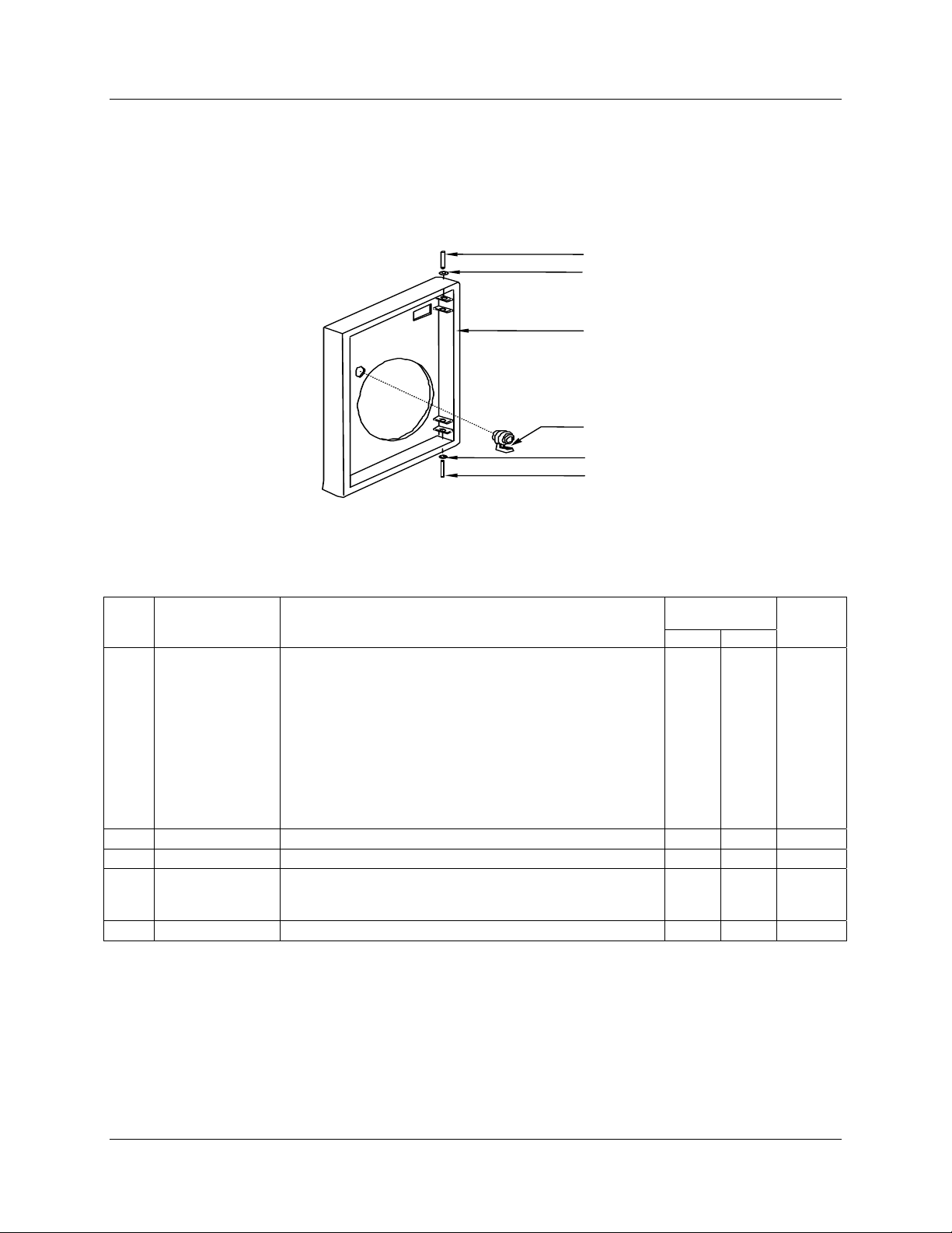
Door assembly
Figure 10-1 is an exploded view of the Door Assembly. Table 10-1 is a list of the associated part numbers.
1-1
1-2
1
1-3
1-3A
1-2
1-1
Figure 10-1 Door assembly
21452C
Table 10-1 Door assembly parts
Key Part Number Description
1
(Note
3)
1-1
1-2
1-3
1-3A
30754955-501
30754955-504
30754955-505
30754955-506
30754955-507
30754955-508
51452435-501
51452435-502
30756548-501
30756548-501
(K)30755980-001 Hinge Pin (Note 1) 2
(K)30755980-001 Retaining Ring (Note 1) 2
51309609-503
30755980-006
51452208-503
51404929-501 External Keypad Upgrade Kit (not shown) 1
Door Assembly
Blue with glass window and latch
Blue with acrylic window and latch
Gray with glass window and latch
Gray with acrylic window and latch
Black with glass window and latch
Black with acrylic window and latch
NEMA4X Door with Acrylic window
NEMA4X Door with Glass window
Stainless Steel Door with Glass window
Stainless Steel Door with Acrylic window
Latch/Lock Assembly Kit
Key kit for keyed latch or lock
NEMA4X Latch Kit
Recommended
Spare Parts per
10 100
1
1 3 1
Quantity
per Unit
NOTE 1: For Door 30754955-50X, (K) denotes that these parts are included in the miscellaneous hardware kit 30755980-001. For all other
doors, the parts are included with applicable door assembly.
222 DR4500A Classic Series Circular Chart Recorder With or Without Control Product Manual Release K
May 2013
Page 3
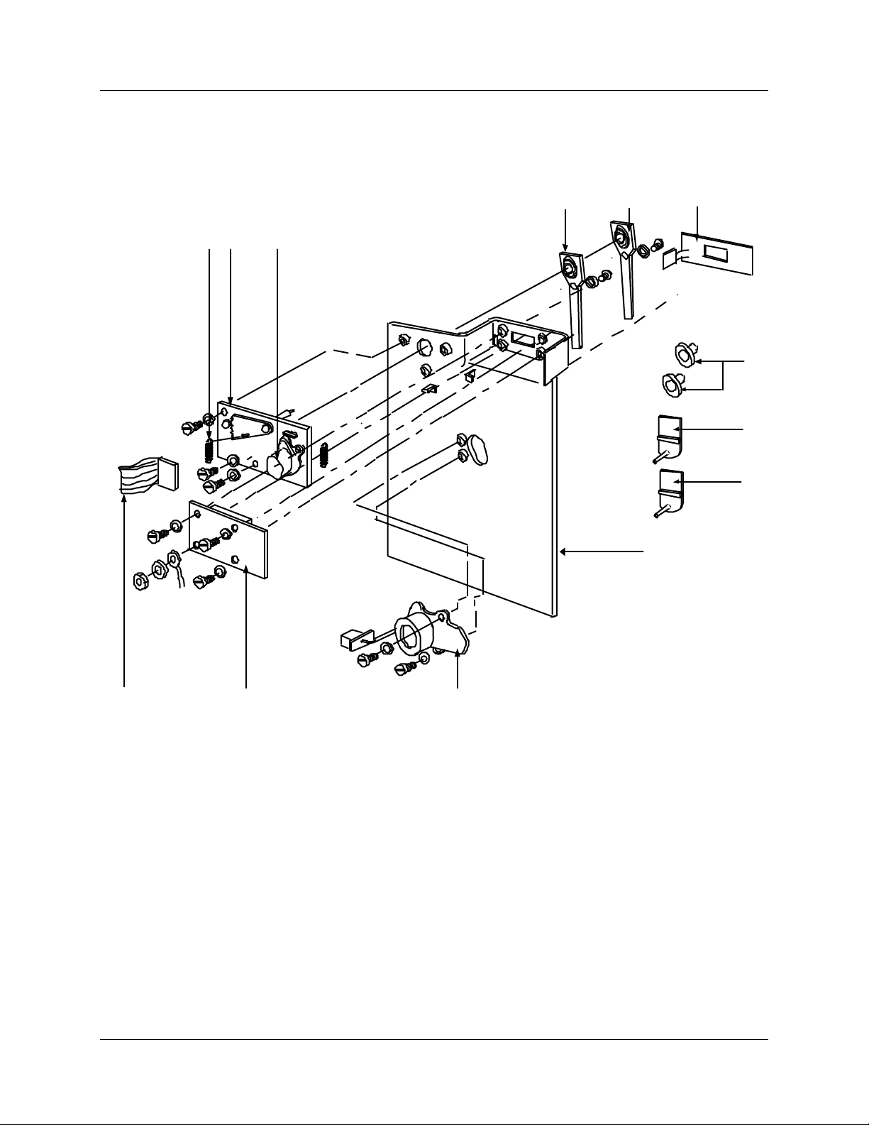
Chart plate
Figure 10-2 is an exploded view of the Chart Plate Assembly.
Table 10-2 is a list of the associated part numbers.
10
12 11
Parts List
Exploded Views
1
2
3
4
5
6
13
9
8
7
22097
Figure 10-2 Chart plate assembly
Release K DR4500A Classic Series Circular Chart Recorder With or Without Control Product Manual 223
May 2013
Page 4
Parts List
Exploded Views
Table 10-2 Chart plate assembly parts
Key Part Number Description
1
(K)30755980-002 No. 2 pen arm (two pen model only) 1 5 1
2
(K)30755980-002 No. 1 pen arm 1 5 1
Recommended
Spare Parts per
10 100
Quantity
per Unit
3
4
5
6
7
8
9
10
11
12
13
30754957-501 Membrane switch keypad 1 5 1
(K)30756150-001 Chart Hub Kit 1 3 2
30735489-007 No. 1 puple pen cartridge (six pack) 2 5 1
30735489-002 No. 2 red pen cartridge (six pack) 2 5 1
30756113-501 Chart motor (includes Chart Hub Kit) 1 3 1
30757571-501 Display PCB (includes key no. 9) 1 5 1
See above Ribbon cable, display (included with key no. 8) 1 3 1
(K)30755980-002 Spring, tension 1
30756114-501 Servo motor assembly 1 3 1
30754975-501
30754975-502
30754977-501
30754977-502
30754977-511
30754977-512
Servo plate assembly (includes key no. 11)
– 1 pen model
– 2 pen model
Chart plate
– 1 pen model
– 2 pen model
– 1 pen model—CE Mark
– 2 pen model—CE Mark
1 2 1
1
224 DR4500A Classic Series Circular Chart Recorder With or Without Control Product Manual Release K
May 2013
Page 5

Basic recorder components without options
Figure 10-3 is an exploded view of the basic recorder components.
Table 10-3 is a list of the associated part numbers.
Parts List
Exploded Views
32
7
145
6
4
21454
4
Figure 10-3 Basic recorder components without options
Release K DR4500A Classic Series Circular Chart Recorder With or Without Control Product Manual 225
May 2013
Page 6

Parts List
Exploded Views
Table 10-3 Basic recorder parts without options
Key Part Number Description
Recommended
Spare Parts per
10 100
Quantity
per Unit
1
2
3
4
5
6
7
30754982-502 Main Transformer 1 3 1
51309355-501 Main PCB 1 5 1
(K)30756141-003 Input PCB (input 1 or 2) 1/3
See Note 2 3-position connector** 2
See Note 2 2-position connector** 1
(K)30755980-005 Fuse (Wilkman 19374-041K 500 ohm or equal)** 1
30754924-502
51452182-502
See Note 2 Card guides for Input PCBs** 2
51197612-502 Ferrite Filter - Package of 2 (CE Mark) 1
51197755-001 Capacitor Kit (.01mfd) - 12 per kit (CE Mark)
30755232-502 0-10 Vdc Input Divider (input PCBs) *
30756461-002 250 ohm Resistor Assembly *
(K)30755065-501
(K)30755065-502
(K)30755065-503
Case
Case NEMA 4
PARTS NOT SHOWN
Mounting Kit (standard)
Mounting Kit (Heavy Duty)
Mounting Kit (NEMA4X)
1
1
(K)30755134-002 Gray Universal Filler Plate Kit *
(K)30755011-001 Filler Panel Kit (for replacing Servoline recorder) *
(K)30757205-008 Kit to Upgrade/Add Totalization to Inputs #1 and #2 for Classic Recorder *
51197657-502 Panel Mounting Gasket Kit 1
NOTE 2: These parts are included with applicable PCB kits, as required.
* As required
** These parts are also included in the miscellaneous hardware kit 30755980-003
226 DR4500A Classic Series Circular Chart Recorder With or Without Control Product Manual Release K
May 2013
Page 7

Additional recorder components associated with options
Figure 10-4 is an exploded view of the recorder components associated with options.
Table 10-4 is a list of the associated part numbers.
1
Parts List
Exploded Views
8
54 3 2 6 7
1 9
10
22098
Figure 10-4 Recorder components associated with options
Release K DR4500A Classic Series Circular Chart Recorder With or Without Control Product Manual 227
May 2013
Page 8

Parts List
Exploded Views
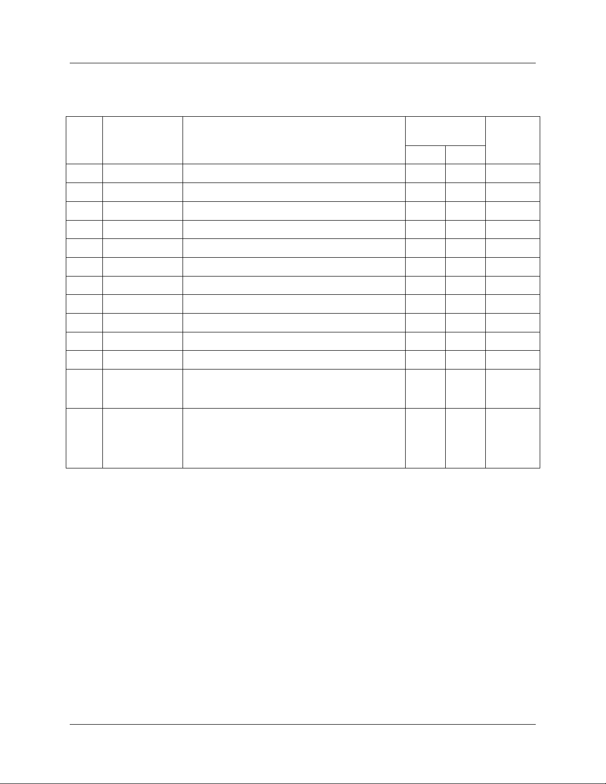
Table 10-4 Recorder parts associated with options
Key Part Number Description
Recommended
Spare Parts per
10 100
Quantity
per Unit
1
2
3
4
5
6
7
8
9
(See
Note
4)
30754922-501
30754922-502
30755306-501
30755306-601
(K)30756140-001 Alarm output/digital input PCB kit 1
30755119-501
30755127-502 Light accessory kit 1
(K)30749598-501
30732192-502 Spacer 1 4
(K)30756141-003 Input PCBs (optional second input) 5 1/2
(K)30755980-004 Battery (Duracell DL2450 or equivalent) 1 3 1
51404561-502
51404561-503
51404561-504
51404561-505
Control Output #1 or #2 PCB
For FM Approved Output PCB
Control Output Relay – 1 relay
Control Output Relay – 5 relays
Ribbon cable (34-conductor)
Kit of 5 Bulbs (General Instruments 1828 or
equivalent)
Original Main board (w/o Daughterboard)
RS485 Comms only
RS485 Comms + 4/ 20 mA Aux Output
Current Main board (with Daughterboard)
RS485 Comms only
RS485 Comms + 4/ 20 mA Aux Output
See Note 3
1 5 1
1 3 1
1
1 5 1
10
30754919-501 Mother board 1 3 0/1
PARTS NOT SHOWN
(K)30757301-001 Configuration Lockout Hardware 1
NOTE 3: Part included with alarm output/digital input PCB kit 30756140-001.
*Includes connectors and standoffs as required.
Note 4: Processor Board change occurred approximately September 2009. See Diagram below for daughter board.
Main board with
Daughter board
Daughter board
228 DR4500A Classic Series Circular Chart Recorder With or Without Control Product Manual Release K
May 2013
Page 9

10.3 Miscellaneous Hardware Kit Contents
Kit contents
Table 10-5 lists the kit contents of miscellaneous hardware kit — part number 30755980-TAB.
Table 10-5 Miscellaneous hardware kit
Part Description
Pen lifter/retainer 1
Screw 10-32, 3/4” lg. 5
O-ring 5
Spring, tension 2
Hinge pin 2
Retaining ring 2
Miscellaneous Hardware Kit Contents
Quantity
Tab
001
Tab
002
Tab
003
Tab
004
Tab
005
Parts List
Tab
006
Pen arm #1 (classic) 1
Pen arm #2 (classic) 1
Latch without lock 1
Latch pin 1
Latch gasket 1
Card guide 2
4-position connector 2
3-position connector 2
3-position connector—CE Mark 2
2-position connector 2
Fuse 0.5 A, 250 V 20
Batteries 3.0 V Lithium Button Cell 5
Key for latch or lock 1
Key for Heavy Duty Door/Keyed latch 1
Noise Suppression Kit 120VAC 51404594-501
Noise Suppression Kit 220VAC 51404594-502
Release K DR4500A Classic Series Circular Chart Recorder With or Without Control Product Manual 229
May 2013
Page 10

Parts List
Internal Cabling Data – Without Options
10.4 Internal Cabling Data – Without Options
View of internal cabling
Figure 10-5 is a view of the internal cabling for the DR4500A Classic Series Recorder.
9 position keyboard cable
Pen 1
Motor
Pen 2
30755064-001, 20 conductor ribbon cable
J2
J3
Display
board
Chassis ground
2 wires (black)
Motor
4 conductor cable
4 conductor cable
4 conductor cable
Pen #1 drive
Chart motor
Pen #2 drive
Chart drive
Chart Plate
Light
option
2 wire pair
111
1
J4
J5 J6
J7
Main
board
J3
J8
J1
J2
4 cond.
cable
Chassis
ground
J13
J12
J14
1
1
J16
1
J3
Second
input
J15
J1
1
1
J3
1
J1
First
input
1
2 wire
orange
pair
J8
Mother board
1
30755119-001
2 wire
gray pair
2 wire
purple pair
2 wire
1
J1
Alarm/digital
inputs
J2
7
c
o
n
d
c
a
b
l
e
34 cond.
ribbon cable
.
Main transformer
black pair
22099
Figure 10-5 Internal cabling for DR4500A Classic recorder
230 DR4500A Classic Series Circular Chart Recorder With or Without Control Product Manual Release K
May 2013
Page 11

10.5 Internal Wiring Diagram – Options Only
View of internal option wiring
Figure 10-6 is a view of the internal wiring diagram—options only for the DR4500A Classic Recorder.
9 position keyboard cable
BRN.
ORG.
PURPLE
GRN. WHT.
BLK. RED
Female
Conn.
BLK. RED
Male
Conn.
T1
Leads
Pen 1 Motor
Pen 2
Motor
Light
Chart motor
option
2 wire light
T1
(See Table 1 for
connections)
J3
Display
board
Chart Plate
Dual Connector
2 wire pair
Internal Wiring Diagram – Options Only
TABLE 1
No.
of
Cond.
Control Output #1
2
Control Output #2
2
Destination
(Board)
Conn.
Designation on
Destinaton Bd.
Auxiliary Output
Modbus RS485
Communications
2
Connection
Modbus RS485
Communications
Processor Card
4
Main transformerGRN. WHT.
Female Conn.
GRN, WHT,
BLK, RED.
Processor
card
Parts List
J4
J4
J4
No
J4Auxiliary Output/
J2
Test
J8
Control Output 1
Auxiliary Output or
Communication
1
1
J1
34 cond.
ribbon cable
J13
Alarm/digital
Control Output 2
Mother board
inputs
Ground
J2
J12
1
J2
4 cond.
cable
22819
2 wire
gray pair
Main transformer
Figure 10-6 Internal diagram for DR4500A Classic recorder – options only
Release K DR4500A Classic Series Circular Chart Recorder With or Without Control Product Manual 231
May 2013
Page 12

Parts List
Internal Wiring Diagram – Options Only
232 DR4500A Classic Series Circular Chart Recorder With or Without Control Product Manual Release K
May 2013
 Loading...