

Page 1
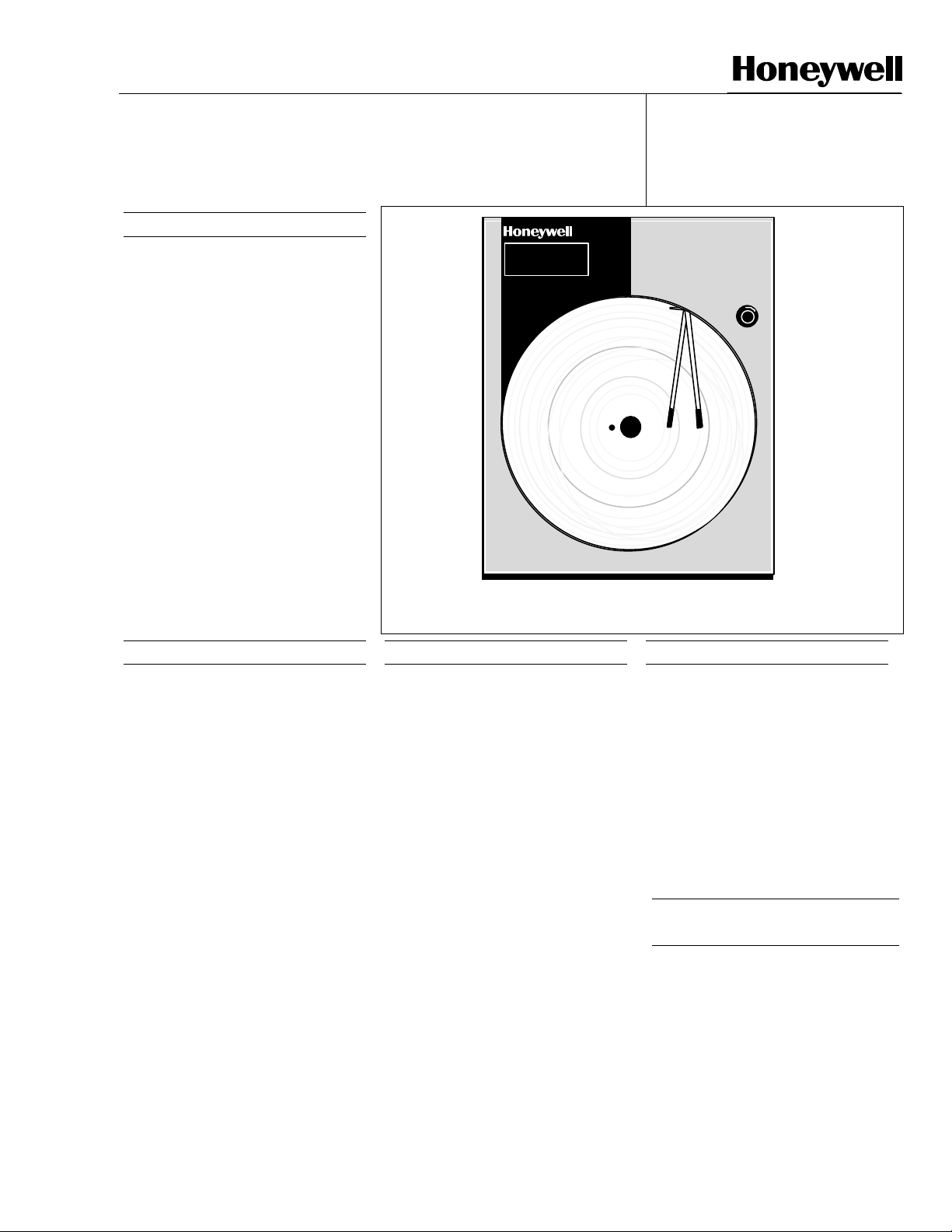
DR4500A Classic Series
Circular Chart Recorder
Function
Honeywell’s Classic Series recorder
combines the simplicity of pen drawn
analog traces with the sophistication
of microprocessor controlled
functions. This combination results in
a user configurable recorder that is
easily adapted to meet a variety of
application requirements—from blast
furnace to laboratory.
In addition to recording analog traces,
the Classic Series recorder
continuously displays process variable
values in the selected engineering
units.
Both one-pen and two-pen models
accept inputs from any one of a
variety of sensors or transmitters
within the configurable range limits.
Also, models are available with one or
two digital controllers to generate
controlled output signals to operate
valves, dampers, heating elements,
etc. for process control.
Figure 1—Classic Series recorder provides analog trace and
continuous digital indication of process variable value.
L
3IN 86.0
3IN 86.0
1559
1559
ruline
44-45-03-15
8/02
Page 1 of 12
Specification
20992
Features
• Charts — Over 5000 preprinted
charts are available to meet specific
recording needs.
• User configurable — means that
users can set and/or alter operating
parameters to fit their requirements,
including type of input, without
recalibration.
English language prompts, coupled
with simple keystroke sequences,
make configuring the recorder easy
and straightforward.
• Operator interface — includes
clear, brilliant alphanumeric displays;
indicators; deviation bargraph; and
keypad for visual and tactile
interaction.
• Ink cartridge — Disposable, fibertip ink cartridge for reliable recording
with minimal maintenance.
• Control Output — up to two versatile PID digital controllers lets users
configure the exact control action
needed for their process.
• Alarms — Integral "soft" alarms are
easily set by users to announce
selected out-of-limit conditions.
Features, continued
• Setpoint Ramp — A single setpoint
ramp is user programmable and is
easily repeated and activated through
the Run/Hold key.
• Setpoint Rate — lets you define a
ramp rate applied to any local
setpoint change. A separate upscale
or downscale rate is configurable.
• Set Point Ramp/Soak
Programming — Lets users program
and store 18 ramp and 18 soak
segments. Run or Hold of program is
keyboard or remote switch
selectable. For each control loop, you
can build up to 6 profiles using any
number of consecutive segments of
the program. You can select a
recovery mode for powerup.
• Accutune II™ — This standard
feature provides a new, truly plug and
play tuning algorithm, which will, at the
touch of a button or through a digital
input, accurately identify and tune any
process including those with deadtime
and integrating processes. This speeds
up and simplifies start-up plus allows
re-tuning at any setpoint.
Features, continued
• Fuzzy Logic — This standard feature
uses fuzzy logic to suppress process
variable overshoot due to SP changes
or externally induced process
disturbances. It operates independently from AccutuneII tuning. It
does not change the PID constants,
but temporarily modifies the internal
controller response to suppress
overshoot. This allows more
aggressive tuning to co-exist with
smooth PV response. It can be
enabled or disabled depending on the
application or the control criteria.
External Interface
Selections
• Alarm Output — Ties “soft” alarms
to up to two integral SPST relays to
activate users external equipment.
• Modbus
option allows you to network your
recorders to take advantage of overall
monitoring of the system using an
RS485 network.
Communications —
Industrial Measurement and Control, 1100 Virginia Drive, Ft. Washington, PA 19034
Printed in U.S.A. © Copyright 2002—Honeywell
Page 2

44-45-03-15
Page 2
External Interface
Selections, continued
• Timer — This optional feature
provides a configurable time period
of 0 to 99 hours, 59 minutes or units
of minutes and seconds. It can be
started via the keyboard, alarm 2, or
by a digital input. The timer output is
Alarm 1, which energizes at the end
of the Timer Period. Alarm 1 can be
automatically reset. The Timer
Period can be changed between
each batch. Status is shown on the
lower display
• Digital Input — Allows users to initiate, from a remote location through
two dry contact closures, selected
recorder functions, such as switching
from automatic to manual control
mode, from direct to reverse
controller action, or reset totalizer.
• Auxiliary Output — there is also a
4 to 20 mA current output available.
It can be used to retransmit a
process variable. In addition, the
4-20 outputs on the control board
can be used as an auxiliary output if
not used for control.
Options
• Two Totalizers — one or two
totalizers are available. Eight digit
totals with multiplier on digital
display.
• Chart Illumination — Lights the
chart area to improve readability in
lower light areas.
• Door Options — Choice of gray,
black or blue doors with standard
latch or optional lock.
Optional UL and FM approved
NEMA4X door available.
• CE Mark — Conformity with
73/23/EEC, Low Voltage Directive
and 89/336/EEC EMC Directive.
• Approval Body Options — FM
approval, CSA certification and UL
Listing or a combination is available.
• Customer ID Tag — (30 characters
max.)
*Restrictions apply -- Not all of the options
an be supplied together
1
ALM
CHN
RSP
OUT
F
X HR
CHRT SP
A
%
FUNC
SET
UP
LOWR
DISP
MAN
AUTO
Figure 2—Operator interface includes displays and keypad for
comprehensive interaction with the recorder and the process.
User Configurable
In the Classic Series recorder,
microprocessor control replaces
conventional electro-mechanical
recording techniques. This means
that the recorder’s capabilities are
now primarily determined by its
software.
Since Honeywell has preprogrammed
a variety of functional capabilities into
the recorder, a user only has to
configure those functions that are
specific for the given application.
The user configures the recorder by
following English language prompts
that appear in the digital displays.
The configuration data (type of input,
chart speed, chart range, alarm
settings, tuning constants, etc.) are
stored in non-volatile memory for
safe keeping in the event of a power
failure.
Operator Interface
Two digital displays present the
process variable (PV) value and by
key selection, the controller set point;
controller output; deviation from
reference input; dry bulb temperature;
totalization value; or engineering units
as desired.
The lower display can also be set
scroll or hold.
In configuration mode, digital displays
are pre-empted by English language
prompts and values that you use to
enter configuration data. Indicators
light to show alarm condition, which
channel PV is on display, use of
remote set point, which output relay is
on, selected temperature unit, and
controller’s mode of operation.
Operator Interface, cont.
A deviation bargraph lets operators
tell at a glance if the process variable
is at, above, or below the controller’s
setpoint.
The keypad through which configuration data is entered also serves as
an integral automatic/manual station
that provides bumpless transfer for
controllers.
On two-pen models, the Hold key
allows continuous display of one
channel process variable while the
recording action proceeds
automatically.
Microprocessor
Controlled Recording and
Printing
Both the chart and the pen are driven
by stepper motors which are
controlled by the microprocessor
for precise maintenance free
operation.
Since chart speed is configurable,
users can easily alter the chart speed
through the keypad. Gear changing or
additional motors are no longer
required.
The stepper motor accurately
positions the pen drive without
damping, thus eliminating the need for
slidewire feedback gearing and drive
cables.
A configurable deviation recording
function lets users show graphically
the difference between reference
input and a process variable input.
Users can designate the channel 1
input or enter a deviation setpoint
value as the reference input. This is
an example of the versatility derived
from microprocessor controlled
recording.
CHART
RUN
HOLD
20951
Page 3

Input Processing
The input can be one of many
standard low-level electrical signals.
And, for models with 2 pens, a
relative humidity (wet/dry bulb)
actuation is available using 100 ohm
platinum bulbs (α = 0.00385). The
input type and range are user
configurable.
Ranges are easily expanded and
compressed within their span
limitations to meet specific
measurement needs. Users can
select upscale or downscale sensor
break protection for many of the
actuations.
Each input is sampled at a rate of 3
times per second. Each sample is
amplified and then converted to a
digital signal, which is isolated and
passed to the microprocessor.
A digital filter with configurable time
constants lets users apply input
signal smoothing as desired.
All non-linear inputs are linearized by
the microprocessor, using look-up
tables that reside in the software.
This allows mixed input actuations
for 2-pen models to be recorded on a
linear chart. Users can bypass
linearization for recording on a nonlinear chart.
An integral 24 Vdc power supply,
along with 4-20 mA input
configuration, allows direct operation
with up to two transmitters without
the need for any additional/external
transmitter power supply.
To totalize a variable, such as a flow
signal, users select the applicable
input and set the digital display
scaling factor through configuration.
This eliminates the need for
additional integration hardware
including a mechanical counter. The
totalizer has an eight-digit display.
Also has capability to reset the
totalizer remotely with digital inputs,
and a low flow cutoff can be set in
percent of range below which the
applicable totalizer does not
increment.
Digital Controller
The DR4500A Series recorder
controller (1 or 2 loops) includes an
integral microprocessor-based PID
controller.
A variety of output types, including a
duplex variation for heat-cool
applications, lets users select the
output that is right for their final
control element.
Depending on the output type users
can configure the control action as
On-Off, PID-A, PID-B or PD with
Manual Reset.
As with the record functions, English
language prompts quickly guide
users through the entry of all the
controller’s configurable parameters.
Diagnostics
All DR4500A Series recorders
include self-diagnostic systems that
check critical operations and provide
error messages to alert users about
detected faults.
Power-up self-diagnostics is a
microprocessor controlled diagnostic
program that runs tests on selected
circuitry when the recorder is
powered up.
A “key” test allows a user to initiate,
on demand, a self-diagnostic routine
that checks the keypad and front
panel displays.
44-45-03-15
Page 3
Construction
The DR4500A Series recorder is
housed in a molded case, which can
be panel or surface, mounted.
A gasketed door with a glass or
optional acrylic window protects
internal components from harsh
industrial environments while allowing
easy access to the chart and operator
interface.
Circuitry is partitioned on printed
circuit boards for ease of service.
A UL and FM approved NEMA4X
door is also available.
Process Interface
Power, input, and output wiring
connect to terminations inside the
case.
Knockouts in the sides and bottom of
the case accept conduit connections
for convenient wire entry.
Page 4

44-45-03-15
Page 4
Specifications
Design
Digital Indication Accuracy
Minimum Input Span
Input Impedance
Source Impedance
Span Step Response Time
Sampling Rate
Input Filter
Digital Displays
Indicators
Deviation Bargraph
1 digit
Range is fully configurable with span limitation of the operating range selected.
4-20 mAdc: 250 ohms
0-10 Vdc: 200K ohms
All others: 10 Megohms
RTD: 100 ohms per lead maximum
6-seconds maximum with no filtering
Each input sampled 3 times a second.
Software: Single pole low pass section with selectable time constants (off to 120
seconds).
Vacuum fluorescent, alphanumeric.
A six-digit display dedicated to the process variable.
Alternate information displayed during configuration mode.
An eight-digit display shows key selected operating parameters. Also provides
guidance during configuration.
Channel PV display (CHN 1 or 2)
Alarm status (ALM 1, 2)
Controller Output (OUT 1, 2)
Remote Set Point (RSP) for Control 1
Temperature unit (F or C) or Engineering units
Controller’s mode (A or MAN)
21 segment, color coded deviation bargraph:
Green (large) = On Control
Green (Small) = Deviation to ± 10% of PV
Controller Modes of Operation
Transmitter Supply Voltage
Manual Operation
Automatic with local set point
Automatic with remote set point
22 to 26 Vdc at input terminals (50 mAdc at 24 Vdc)
Page 5

Specifications, continued
Performance
44-45-03-15
Page 5
Number of Inputs
One Pen model: One input
Two Pen model: Two inputs
Range Reference Accuracy Types of Input
Actuation
1
˚F ˚C ± ˚F ± ˚C
Thermocouples2
B
E
E (low) -200 to 1100 -129 to 593
J 0 to 1600 -18 to 871
J (low) 20 to 770 -7 to 410
K
K (low) -20 to 1000 -29 to 538
NNM (Ni Ni Moly) 32 to 2500
105 to 3300
105 to 150
150 to 500
500 to 1000
1000 to 3300
-454 to 1832
-454 to -202
-202 to 1832
-320 to 2500
-320 to 0
0 to 2500
32 to 500
500 to 2500
41 to 1816
41 to 66
66 to 260
260 to 538
538 to 1816
-270 to 1000
-270 to -130
-130 to 1000
-196 to 1371
-196 to -18
18 to 1371
0 to 1371
0 to 260
260 to 1371
42.00
14.00
3.00
1.50
18.00
1.00
0.50 0.30 0.20
0.40 0.22 0.06
0.20 0.11 0.04
1.25
0.60
0.30 0.16 0.05
0.75
0.50
23.00
7.70
1.70
0.80
10.00
0.55
0.70
0.35
0.40
0.30
Temp. Stability ±
Degrees Error Per 1
Degree ∆T
2.00
2.00
0.50
0.20
0.70
0.35
0.18
0.09
0.09
0.07
NIC (Nicrosil
Nisil)
R
S
T -300 to 700 -184 to 371
T (low) -200 to 600 -129 to 316
W5W26
W5W26 (low)
Radiamatic 1400 to 3400 760 to 1871
0 to 2372 -18 to 1300
0 to 3100
0 to 500
500 to 3100
0 to 3100
0 to 500
500 to 3100
0 to 4200
0 to 600
600 to 3600
3600 to 4200
0 to 2240
0 to 600
600 to 2240
-18 to 1704
-18 to 260
260 to 1704
-18 to 1704
-18 to 260
260 to 1704
-18 to 2315
-18 to 316
316 to 1982
1982 to 2315
-18 to 1227
-18 to 316
316 to 1227
1.0 0.55 0.01
2.00
1.00
2.00
1.00
0.60 0.35 0.07
0.40 0.22 0.07
1.40
1.30
1.60
1.10
1.00
1.00 0.55 0.10
1.10
0.55
1.10
0.55
0.77
0.70
0.90
0.60
0.55
0.25
0.13
0.23
0.13
0.17
0.17
0.29
0.14
0.10
Page 6

44-45-03-15
Page 6
Specifications, continued
Types of Input
Actuation
RTDs
Platinum
100 ohms
500 ohms
Linear
Milliamperes dc
Millivolts dc
Volts dc
Relative Humidity
Platinum
100 ohm Wet/Dry
Wet/Dry Input
Bulb* %RH3
1
Range Reference Accuracy
˚F ˚C ± ˚F ± ˚C
–300 to 900
–300 to 900
4 to 20
0 to 10
10 to 50
1 to 5 (can be
calibrated 0 to 5)
0 to 10
–130 to 392
Measured %RH
–184 to 482
–184 to 482
--
--
--
--
--
–90 to 200
Dry Bulb Range
°F °C
0.40
0.20
0.10%
0.05%
0.05%
0.05%
0.10%
0.30
0.22
0.11
--
--
--
--
--
0.03
Reference
Accuracy
°F ± °C
±
Temp. Stability ±
Degrees Error Per
1 Degree ∆T
0.05
0.05
0.004% /
0.004% /
0.004% /˚F
0.004% /˚F
0.004% /˚F
0.03
Temp. Stability
53 to 104
12 to 40
˚F
˚F
°F/
°C
0 to <20
20 to 100
-103 to 212
35 to 40
>40 to 100
100 to 212
-75 to 100
2 to 4
>4 to 38
38 to 100
2% RH
2% RH
1% RH
1% RH
0.11% RH/˚F
0.11% RH/
0.06% RH/
0.03% RH/
˚F
˚F
˚F
1
Consult Model Selection Guide 44-45-16-07 for information.
2
Includes reference junction calibration of ± 0.01degrees using standard “ice bath” method of calibration. Factory calibration at reference
± 1.2˚F. Note that factory calibration may vary by as much as ± 10 microvolts or ± 0.3 ohms for RTDs which means recalibration may be
required to achieve stated accuracy.
3
The RH calculation is inoperative when temperature goes below 32 ˚F (0 ˚C) or above 212 ˚F (100 ˚C). However, the dry bulb temperature
will be monitored to -103 ˚F (-75 ˚C). Accuracy stated is for Classic Series Recorder only, and does not include remaining system accuracies.
*IEC Alpha (α) = 0.00385 Ω/Ω/˚C
Page 7

44-45-03-15
Page 7
Specifications, continued
Configurable Parameters: These parameters can be set through the keypad.
Group Parameters Setting Range or Selection Resolution
INPUT 1 and
INPUT 2
PEN 1 and PEN 2
CHART
TOTAL 1 and
TOTAL 2
Decimal point location
Units
Actuation type
Transmitter characterization
High range value
Low range value
Low Flow Cutoff
Input compensation
Filter 1
Sensor break protection
(burnout)
Pen 1
Pen 1 input
Chart 1 high range value
Chart 1 low range value
Pen 1 On
Pen 1 Off
Chart speed
Hours per revolution
Linearize
Total
Reset total
Total 1(2)
Total engineering units
Rate
Scaling factor
Resettable
None, 1 (XXX.X), 2 (XX.XX), or 3 (X.XXX)—
one decimal place only for non-linear inputs
°F, °C, or engineering units
See Input types
All non-linear input types, linear, square root
-999.0 to 9999
-999.0 to 9999
0 to 100% of input range
-999.0 to 9999
0 to 120
None, Up or Down
Disable or Enable
Input 1, Output, SP, Dev, Dgtl1, Dgtl2, Input 2, Out2,
SP2, Dev2
-999.0 to 9999
-999.0 to 9999
0 to 100% of chart
0 to 100% of chart
8 hrs, 12 hrs, 24 hrs, 7 days, or selected hours per
revolution
1 to 744 hrs
Linear or Non-linear Chart
Read only
Yes or No
Disable, Input 1, Input 2
Desired alphanumeric title
Second, Minute, Hour, Day or Million/Day
1, 10, 100, 1000, 10,000, 100,000 or 1E6
No, Local, Ext Sw1, Ext Sw2
0.1
0.1
0.1
1
0.1
0.1
1
1
Control 1 (2)
TUNING 1(2)
PID tuning sets
Setpoint source
Ratio (Input 2)
Bias
SP tracking
Power-up mode recall
High and low SP limits
Action
High and low output limits
Dropoff value
Deadband
Output Hyst
Failsafe output value
Remote Switching
Man Key
PB or Gain
Reset units
Control 1 Algorithm
Output 1 Algorithm
Gain (or Prop Band)
Rate Min (or RPM)
Reset Min
Man Rset
Cyc Sec
1 or 2
Local, Remote (Control 1 only), or 2 Local
-20.00 to 20.00
-999 to 9999
None or RSP (Control 1 only)
Manual, Auto LSP, or Auto RSP, AM, SP, AMLSP
0 to 100% of span in engineering units
Direct or reverse
-5 to 105% of output
-5 to 105% of output
-5.0 to 25% of PV Span
0.0 to 5.0% of PV Span
Within the output limits
None, ToMan, ToLSP, To2SP, ToDir, RN/HLD
Disable or Enable
Proportional band (%) or gain
Repeats/minute or minutes/repeat
PIDA, PIDB, PD + MR, ON-OFF
Current, Position Prop, TimeD, Cur TI, TI Cur, Time
0.1 to 1000
0.00 to 10.00
0.02 to 50.00
-100 to 100% output
1 to 120 sec.
0.01
1
1
1
1
1
0.1
0.01
0.01
1
1
Page 8

44-45-03-15
Page 8
Specifications, continued
Controller
Group Parameters Setting Range or Selection Resolution
SPRAMP 1(2)
SPPSEGS Profile Start Segment
SPP EVENT Segment X Event None, Alarm 1, 2, 3, 4, 5, or 6
TIMER Timer
AUXILIARY
OUTPUT
ALARMS
(1,2,3,4,5,6)
SP Ramp (1 or 2)
Time Min
Final SP
SPRate
EU/HR UP
EU/HR DN
SP Program
Recycles
Soak Deviation
Profile
State
Recovery
Program End
Profile End Segment
Ramp Unit
Synchronize Profiles
Segment X Ramp
Segment X Setpoint
Segment X Time
Period
Start
Ldisplay
Reset
Increment
Aux Output
4mA Val
20mA Val
SP Value
SP Type
Alarm Type
Alarm Scaling Multiplier for
Totalizer Alarm
Alarm Hysteresis
Disable or Enable
0 to 255
0 to 100% of Span
Enable or Disable
0 to 9999
0 to 9999
Disable or Enable
0 to 99
0.0 to 99.0
1 to 6
Disable or Hold
Enable or Disable
Last Setpoint or Failsafe
Ramp 1 to Ramp 35
Soak 2 to Soak 36
Time or Rate
Enable, Disable
0.00 to 99:59
within High/Low Range Limits
0.00 to 99.59
Enable/Disable
0.00 to 99:59
Run/Hold Key or Alarm 2
Time Remaining or Elapsed Time
Run/Hold key or Alarm 1
Minute or Second
Disable, IN1, IN2, PV1, PV2, Dev1, Dev2, Out1(2),SP1 (2)
Low scaling factor
High scaling factor
0.0 to 9999
None, Input 1 (2), RH, Dev, Output, Total 1, Total 2, Dev2,
Out2, Event
High or Low
1,10,100,1000,10000,100000, 1E6
0.0 to 100% of span
0.1
OPTIONS
MODBUS Communications State
LOCKOUT Lockout (Software and/or
STATUS
Reject Frequency
Relative Humidity
Atm. Pressure
Deviation
Scroll (Lower Display)
Communications Address
Baud
Transmit Delay
Hardware)
Version
Failsafe
RAM Test
Configuration Test
Calibration Test
Fact CRC (Factory Set Input
Constants)
Battery Test
60 or 50 Hz
Yes or No
590 to 800
None, SetPnt, Chan 1
None, 1 sec, 2 sec, 3 sec
Enable/Disable
1 to 99
300, 600, 1200, 2400, 4800, 9600, 19200, 38400
None, 10msec, 20msec, 30msec, 40msec, 50msec.
None, Calib, +Conf, Max
Hardware Configuration Lockout (Optional)
Latest Software Version
Yes or No
Pass or Fail
Pass or Fail
Pass or Fail
Pass or Fail
Pass or Fail
Page 9

Specifications, continued
Controller (continued)
•
Controller
1
Output
(Optional)
On-Off or Time Proportional
One SPST electromechanical relay. Control action can be set for direct or reverse;
N.O. or N.C. contact selectable.
• On-Off Duplex or Time Proportional Duplex
Two SPST electromechanical relays. Control action can be set for direct or reverse;
N.O. or N.C. contact selectable.
• Current Proportional
21 mAdc maximum into a negative or positive grounded or non-grounded load of 0 to 1000 ohms.
Output range can be set between 4 and 20 mA, and as direct or reverse action.
Resolution: 10 bits
Accuracy: 0.5 % full scale
FM Approved Output (Optional)
• Position Proportional
Two SPST electromechanical relays operate motor having a 100 ohm to 1000 ohm slidewire.
• Current/Time Duplex and Time /Current Duplex
Variation of time proportional duplex for Heat/Cool applications. Time proportional output (heat or
cool) is a SPST electromechanical relay. Current proportional output (heat or cool) is a 4-20 mA signal
that can be fed into a negative or positive grounded load of 0 to 1000 ohms and is operational over 50
% of range or the entire range.
Time Proportional Relay Resolution: 4.4 mSec.
Relay Contact Ratings:
Resistive Load: 5A @ 120 Vac, 2.5A @ 240 Vac
Inductive Load: 50 VA @ 120 Vac or 240 Vac
Cycle Time: 1 to 120 seconds
Current Proportional:
Resolution: 10 bits
Accuracy: 0.5 % full scale
44-45-03-15
Page 9
CE Conformity
(Europe)
(Optional)
Product
Classification:
Enclosure Rating:
Installation
Category (Overvoltage Category)
Pollution Degree:
EMC Classification
Method of EMC
Assessment
Declaration of
Conformity
This product is in conformity with the protection requirements of the following European Council
Directives: 73/23/EEC, the Low Voltage Directive, and 89/336/EEC, the EMC Directive. Conformity of
this product with any other “CE Mark” Directive(s) shall not be assumed.
Class I: Permanently Connected, Panel Mounted Industrial Control Equipment with protective earthing
(grounding). (EN 61010-1)
Panel Mounted Equipment, IP 00, this recorder must be panel mounted.
Terminals must be enclosed within the panel. Front panel IP 65 (IEC 529)
Category II: Energy-consuming equipment supplied from the fixed installation.
Local level appliances, and Industrial Control Equipment. (EN 61010-1)
Pollution Degree 2: Normally non-conductive pollution with occasional conductivity caused by
condensation. (Ref. IEC 664-1)
Group 1, Class A, ISM Equipment (EN 55011, emissions), Industrial Equipment (EN 50082-2, immunity)
Technical File (TF)
51197635-000
Page 10

44-45-03-15
Page 10
Specifications, continued
Controller, continued
Case/Door
Molded, foamed-Noryl** with gasketed door to meet NEMA 3 enclosure requirements. Panel gasket
available separately.
An optional UL and FM approved NEMA4X door is also available.
Pen
Chart
Wiring
Connections
Color
Approval Bodies
Dimensions
Weight
Mounting
Options
Auxiliary Linear
Output (Optional)
Alarm Output
Disposable fiber-tip ink cartridge. Line length per cartridge more than 1000 ft (305 m).
One Pen: Purple
Two Pens: Purple and Red
12-inch (304.8mm) diameter chart with standard preprinted markings and a calibrated width of
4.62-inches (117.5mm).
Terminals inside the case
Case: Black
Door (standard): Caribbean Blue, Black or Gray
U.L. approval depending on model. Consult Model Selection Guide for information.
FM approved for Class I, Div 2, Groups A, B, C, D areas depending on model.
See Figure 3.
13.2 lb. (6 kg)
Panel or surface mounted. Some adapter kits available for existing panel cutouts.
Three Auxiliary Outputs are available:
21 mA dc maximum into a negative or positive grounded load or non-grounded load of 0 to 1000 ohms.
Output range can be set between 2 to 21 mA, and as direct or reverse action. It can be configured to
represent any one of 10 parameters: Input 1-2, PV 1-2, Deviation 1-2, Output 1-2, Setpoint 1-2. The
range of the auxiliary output, as a function of the selected variable, can be scaled.
Auxiliary Output 2 and Auxiliary Output 3 use Control Current Output 1 and Control Current Output 2 if
Control “OUTALG” is not set to “CURRENT” or “POSITION”.
Resolution: 12 bits over 0 to 21 mA (10 bits for Auxiliary Output 2 and 3)
Accuracy: 0.2 % of full scale
Temperature Stability: 0.03% F.S. / °C
Two SPST electromechanical relays
Digital Input
Totalizers
Miscellaneous
** Registered Trademark -- General Electric Co.
1. Not all controller outputs are available on all models of the Classic Recorder. Consult Model Selection Guide 44-45-16-07 for information.
Relay Contact Ratings:
Resistive Load: 1A @ 120 Vac, 1/2A @ 240 Vac.
+20 Vdc source for external dry contact or isolated solid state contacts. Selects one configured input.
One or two Totalizers depending on model.
Eight digit “totals” with multiplier on digital display.
• FM Approved 4-20 mA Control Output
• UL and FM approved NEMA4X door
• Door Lock
• Chart Illumination
• UL Listing, FM Approval, CSA, CE Conformity
• Control with Accutune II tuning capability
• Customer ID Tag
• 4-20 mA Auxiliary Output
Page 11

Specifications, continued
Environmental and Operating Conditions
Parameter Reference Rated Extreme Transport and storage
44-45-03-15
Page 11
Ambient
Temperature
Relative
Humidity (%RH)
Vibration
Frequency (Hz)
Acceleration (g)
Mechanical Shock
Acceleration (g)
Duration (ms))
Mounting Position from
Vertical
Tilted Forward
Tilted Backward
Tilted to Side (± )
Power Requirements
Voltage (VRMS)
Frequency (Hz)
Power Consumption
General Reference Data
67 to 77
19 to 25
0 to 55*
0
0
0
0
5˚
5˚
5˚
119 to 121
238 to 242
49.8 to 50.2
59.8 to 60.2
20 watts maximum
˚F
˚C
58 to 131
15 to 55
10 to 90*
0 to 70
0.1
1
30
5˚
30˚
10˚
102 to 132
204 to 264
49 to 51
59 to 61
˚C
˚F
32 to 131 ˚F
˚C
0 to 55
5 to 90*
0 to 200
0.2
5
30
5˚
90˚
20˚
102 to 132
204 to 264
48 to 52
58 to 62
–40 to 151 ˚F
–40 to 66
5 to 95*
0 to 200
0.5
20
30
Any
Any
Any
N/A
N/A
N/A
N/A
˚C
Stray Rejection
Static Charge Effects
Line Noise Effects
Technical Assistance
* The maximum rating only applies up to 104 ˚F (40 ˚C). For higher temperatures, the RH specification is derated to maintain constant
moisture content.
Common Mode Rejection Ratio: 120dB or 1 LSB (whichever is greater) at 60 Hz with
maximum source impedance of 100 ohms.
Normal Mode Rejection Ratio: 60dB with a 100% span peak-to-peak maximum at 60 Hz.
Exposed panel surfaces capable of withstanding a discharge from a 250pf capacitor charged to
10KV through 100 ohms.
Field terminals for connecting power line to recorder can withstand the IEEE Surge Withstanding
Capability Test to a level of 2.5KV.
Toll-free 800 number puts technical assistance only a phone call away.
WARRANTY/REMEDY
Honeywell warrants goods of its manufacture as being free of defective materials and faulty workmanship.
Contact your local sales office for warranty information. If warranted goods are returned to Honeywell during the
period of coverage, Honeywell will repair or replace without charge those items it finds defective. The foregoing
is Buyer's sole remedy and is in lieu of all other warranties, expressed or implied, including those of
merchantability and fitness for a particular purpose. Specifications may change without notice. The
information we supply is believed to be accurate and reliable as of this printing. However, we assume no
responsibility for its use.
While we provide application assistance personally, through our literature and the Honeywell web site, it is up to
the customer to determine the suitability of the product in the application.
Page 12

44-45-03-15
Page 12
Dimensions:
Standard DR4500
17.5
0.69
12.6
Bottom view
millimeters
inches
321
Reference
20.3
0.8
321
12.6
419
16.5
163
6.4
196
7.7
Surface mounting
14.6
370
181
7.1
Short wing latch :
Double bit latch :
Left side view
14.5
.57
.19
5
NEMA4X DR4500
17.5
0.69
Bottom view
321
12.6
106
4.2
Reference
321
12.6
106
4.2
20.3
0.8
142
142
5.6
355
5.6
11.0
.43
14
Front view
387
15.25
Front view
NEMA4X
438
17.25
z
z
z
Surface mounting
z
z
Back view
zzzzz
zzzzz
Back view
322
12.7
z
z
z
z
z
322
12.7
Panel cutout (all models)
Figure 3—DR4500A series recorder dimensions - for reference only
Ordering Information
For complete ordering information, request Model Selection Guide 44-45-16-07 for DR4500A Series Circular
Chart Recorder.
Honeywell offers a full line of sensors and transmitters that produce a compatible range of dc voltage or
current signals which can be used as inputs to the DR4500A Series Recorder.
These devices measure:
Temperature: (Thermocouple or RTD)
Pressure
Flow
{4 to 20 mA dc or 1 to 5 Vdc process transmitter}
Liquid Level
Relative Humidity
Specifications are subject to change without notice.
Industrial Measurement and Control
Honeywell
1100 Virginia Drive
Ft. Washington, PA 19034
44-45-03-15 0802 Printed in USA www.honeywell.com/imc/
 Loading...