

Page 1

1 EN1C-9999SZ22 R1104
R4348B
INDUSTRIAL FLAME SWITCH
PRODUCT HAND BOOK
APPLICATION
The R4348B flame switch is for application in large commercial and industrial burner installations.
The function is:
flame safeguard primary controls capable of providing
system „safe start“ check and flame sensing functions.
The unit can also be used in installations using an EC7800
microcomputer-based burner control system - to extend the
number of burners being controlled.
The unit includes a 3-pole flame relay which is energized when
flame is sensed and de-energized when „no-flame“ is sensed
and a 3-pole line voltage „load relay“.
• Standard is a green LED which is illuminated when the
flame relay is energized.
• R4348B1057 only:
– LED bar and 4-20mA output for indicating and / or
recording the flame current strength.
• Unpowered relay outputs enable Honeywell sensors
and amplifiers to be used with a wide range of logic
schemes according to customer needs.
• Plug-in unit makes wiring and servicing easy.
• Plug-in flame signal amplifiers available to match a wide
range of flame sensors.
Page 2
EN1C-9999SZ22 R1104 2
SPECIFICATIONS
WARNING
To avoid the risk of electrical shock which could
cause personal injury, follow all safety notices in this
documentation.
MODEL:
R4348B industrial flame switch with 3-pole flame relay
and 3-pole load relay
1)
see OPTIONS also
ELECTRICAL RATINGS:
can operate on 110V - 120V - 127V - 230V 50/60Hz
POWER CONSUMPTION:
less than 15VA
ENCLOSURE:
IP40 or IP54 depending on the model and base
AMBIENT TEMPERATURE LIMITS:
Operating: - 20°C to + 60°C.
Storage: - 40°C to + 80°
CLASSIFICATION:
OOCRXB
APPROVALS:
Installation and cabling for both intermittent and
continuous operations must be in accordance with
relevant standards (i.e. EN298)
OPTIONS: (see MODELS also)
LED-METER. A series of color coded LED’s on the face of
the unit which give a direct indication of flame current
strength.
Green LED’s indicate normal flame current strength. Yellow
LED’s indicate marginal signals. Red LED’s indicate
unsatisfactory flame signal strength (see fig. 2).
4-20mA OUTPUT. The flame current value can be
registered and/or displayed at a local or remote location.
Load : 0 to 750Ω.
.
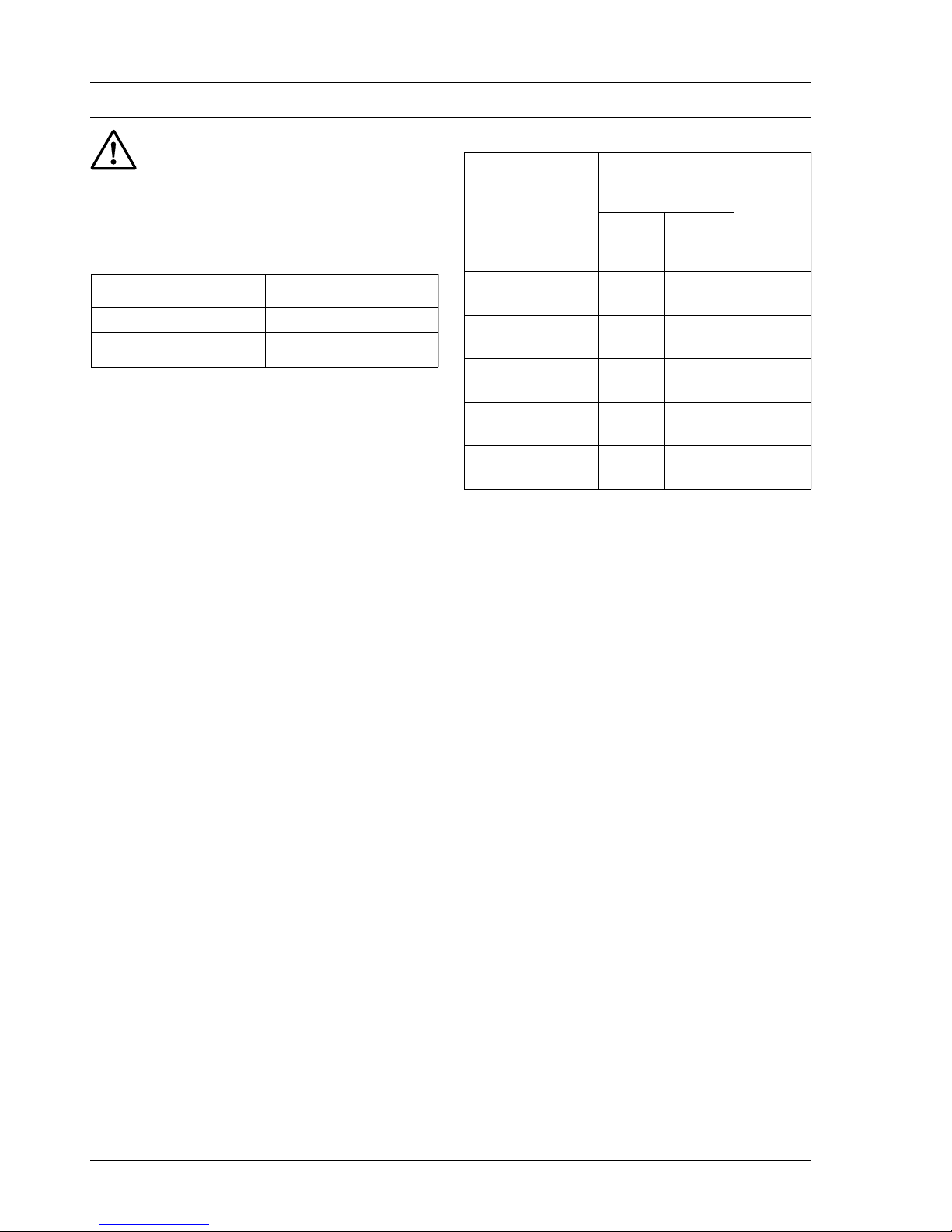
CONTACT RATINGS:
If more than one safety shut-off valve is to be actuated by
the R4348 it is recommended to use separate relay contacts
rather than paralleling from one contact.
MAXIMUM RELATIVE HUMIDITY:
90 % RH at 40oC (not to exceed saturation point)
WEIGHT : 1,5 Kg
FLAME SENSORS AND AMPLIFIERS :
will accept any of the plug-in amplifiers and appropriate
sensor listed .
FLAME INDICATION :
Green LED on face of unit when illuminated indicates
presence of flame. Relay contact enables remote indication of flame presence to be made.
MOUNTING :
Can be wall, DIN rail of panel mounted.
Subbase: 46176612-501
SREBMUNLEDOMSETON
)1
8001B8434Rledomdradnats
7501B8434RtuptuoAm02-4htiw
retem-DELdna
daoL
lacipyT
rewop
rotcaf
tnerrucmumixaM
suounitnoc(gnitar
)noitarepo
mumixaM
hsur-nI
tnerruc
V032
V011
V021
V721
dioneloS
evlav
4.0A5.1A2detarx01
tnerruc
dezirotoM
evlav
5.0A2A4detarx3
tnerruc
renruB
rotom
6.0A3A3detarx5
tnerruc
noitingI
remrofsnart
2.0A5.2A4detar
tnerruc
rehtO59.0A4A4detar
tnerruc
Page 3

3 EN1C-9999SZ22 R1104
FIG. 1 Dimensions in mm.
FIG.2 Main features
ACCESSORIES:
Subbase : 46176612-501 : for IP40 (to be ordered separately)
158
88
88
TOP VIEW
11x Pg11
ø4,5
3015
30
30
45
82
200
100
15
45
20 (minimum) required for unplugging
R4348B from the subbase
20
Front view
Rear view
subbase
Page 4

EN1C-9999SZ22 R1104 4
SREIFILPMAEMALFNI-GULP SROTCETEDEMALFELBACILPPA
-NOITCETED
EDOM
ROLOC
FLES
GNIKCEHC
LEDOM
EMALF
ERULIAF
-NOPSER
EMITES
).XAM(
LEUFEPYTSLEDOM
MUMINIM
EMALF
TNERRUC
)Aµ(
-ACIFITCER
NOIT
NEERG
ON
A1237R.ces1
saG
gniyfitceR
sdoremalf
sredlohdoR
)3
:
1107C/7007C/4007C
seilbmessaetelpmoC
/8007C/5007C
971Q/9007C
2
liO
)4
/0107C/3007C
4107C/3107C
B1237R.ces3-2
,liO,saG
laoC
teloivartlUGROA2107C
SEY
B7427R
)2
,.ces1
ro.ces2
.ces3
.xam
saG
gniyfitceR
sdoremalf
sredlohdoR
)3
:
1107C/7007C/4007C
:seilbmessaetelpmoC
/8007C/5007C
971Q/9007C
52,1
C7427R
)1
ro.ces2
.ces3-2
,liO,saG
laoC
teloivartlUFroE2107C2
)5
ARTLU
TELOIV
TELOIVON
A3237R
B3237R
.ces1
.ces3-2
,liO,saGteloivartlU4407C/5307C/7207C5.3
EULBSEY
B6747R
)1
ro.ces2
.ces3-2
,liO,saG
laoC
teloivartlU
elbatsuda(
)ytivitisnes
6707C5.2
)5
TELOIVSEY
A1607Rro.ces1
ro.ces2
.ces3-2
,liO,saG
laoC
teloivartlUA1607C5.2
1) Dynamic Self Check circuitry tests all electronic components in the flame detection system (amplifier and
detector) 60 to 120 times/min. during burner operation
and shuts down the burner if the detection system fails.
2) Circuitry tests only the flame signal amplifier during burner operations and shuts down the burner if the amplifier fails.
3) Order flame rod separately, see instruction sheet for the
holder
4) Use Honeywell photocell. Part No 36316 only.
5) C7012E, F and C7076A shutter operation causes fluctuations in the current reading. Read the average stable
current - disregard peaks.
FLAME DETECTION SYSTEM:
Page 5

5 EN1C-9999SZ22 R1104
INSTALLATION
IMPORTANT
1 The installer must be a trained, experienced flame
safeguard technician.
2 When installing the subbase and R4348 industrial
flame switch refer to the instructions provided by the
burner manufacturer. When these are not available
follow the instructions packed with the product.
3 Disconnect power supply before beginning the
installation.
MOUNT THE SUBBASE
The R4348 industrial flame switch can be wall, DIN rail of
panel mounted. When panel or DIN rail mounting the R4348
the appropriate kit must be ordered separately.
WIRE THE SUBBASE
1 All wiring must comply with local codes ordinances and
regulations.
2 Ensure that loads do not exceed the terminal ratings.
SELECTING THE OPERATING VOLTAGE
To match the R4348 to the supply line voltage, select the
proper terminals and the internal connector position per the
following table.
YLPPUS
EGATLOV
ylppustcennoc
...slanimretot
lanretnites
...otparts
V011
V021
V721
V032
3dna2
3dna2
3dna2
1dna2
V011
V021
V721
To have access to the internal connector, remove the 4 cover
retaining screws and slide out the PC board.
Page 6

EN1C-9999SZ22 R1104 6
INSTALL THE FLAME DETECTOR
The performance of the flame safeguard system depends
upon correct flame detector installation. Refer to the
instructions packed with the flame detector and also the
burner manufacturer’s instructions for details. (See also
figure 4).
Keep the flame signal leadwires from the flame detector to
the wiring subbase as short as possible. Capacitance
increases with leadwire length, reducing the signal
strength. The maximum permissible leadwire length
depends on the type of flame detector, leadwire, and
conduit. The ultimate limiting factor in the flame signal
leadwire length is the flame current.
MEASURING FLAME CURRENT STRENGTH
Flame current is measured/recorded in different ways
according to the model selected
1 It can be measured conventionally using a micro-
ammeter which is plugged into a jack socket on the
face of the R4348B.
2 It can be displayed/recorded locally or remotely when
the 4-20mA output model is taken.
3 Visually presented on the face of the unit by means of
color coded LED’s.
The customer can choose a model which includes two
methods of flame current measurement. e.g. Flame current
jack socket for local testing by a service technician plus 420mA output for remote indication.
PLUGGING THE R4348 INTO THE SUBBASE
1 Plug the selected amplifier into the back of the R4348
(see fig. 3).
Make sure the correct combination of amplifier and
flame detector is used.
2 Check that wiring connections are correct and that all
terminal screws are tight.
3 Plug the chassis into the subbase and tighten the two
captive screws.
4 In case of B1057 model, plug the cable into the back-
side of the amplifier.
FIG. 3 Installing a plug-in flame current amplifier
Page 7

7 EN1C-9999SZ22 R1104
Wires are identified by color code as follows :
0=black
4=yellow
6=blue
9=white
FIG. 4 Flame detector wiring diagrams
Page 8

EN1C-9999SZ22 R1104 8
FIG. 5 Industrial flame switch - terminal location
Page 9

9 EN1C-9999SZ22 R1104
CHECK OUT AFTER INSTALLATION
INSTALLATION CHECKOUT
Preliminary inspection - make certain that :
1 System overload protection is correct (5A max.).
2 Wiring connections are correct and all terminal screws
tight.
3 Flame detector installation is complete.
4 The correct flame detector is used. Refer to table page 5.
5 Burner is completely installed and ready to fire with the
fuel lines purged of air.
6 Combustion chamber and flues are clear of fuel.
7 Power is on at the system main switch.
FLAME DETECTOR CHECKOUT
The best guide to the performance of a flame detector is
given by the FLAME CURRENT value.
The expected maximum and minimum values of flame current
for the various types of flame detectors are given in the table
page 12.
Note that the following have an influence on flame sensing
performance :
1 Position, size and burning characteristic of the flame.
2 Refractory - when refractory temperature exceeds
1370C/2500F some ultraviolet radiation may occur.
Lower refractory temperature may affect photocells.
See relevant data sheets.
3 Temperature at flame detector
- Flame rods : ensure suitable rod is being used
- Other detectors : see relevant data sheet.
The R4348B has the possibility of measuring / recording the
flame current value in various ways, as follows :
(see also MODELS).
1 Using a Honeywell W136A micro-ammeter which is
plugged into a socket on the face of the R4348.
2 By reference to an LED-meter on the face of the R4348
which gives the value “at-a-glance”.
3 By relaying the current to existing customer recording/
indicating equipment.
HOT REFRACTORY TEST
In applications using caesium oxide detectors (rectifying
photocells) it is important to determine that hot refractory
does not simulate a flame after the end of normal run. If this
happens a flame condition is simulated after the real flame is
extinguished and a system restart is made impossible.
Test for this condition by operating the burner until the
refractory reaches maximum temperature and then stop the
burner fuel supply. At this point the flame current should
drop below 1mA, followed by a lockout within 0,8 to 1 second.
If this does not happen the photocell may be influenced by
the hot refractory.
THIS CONDITION MUST BE CORRECTED.
Try sighting the photocell at a cooler and/or more distant
refractory background. If that does not eliminate the trouble
try adding an orifice of filter to the detector. Continue to adjust
and test until the hold-in problem is eliminated.
NOTE : Repeat all flame detector tests after ALL adjustments
have been completed. All tests must be satisfied at the FINAL flame detector position.
PILOT TURN-DOWN TEST
Ensure that any pilot which can be detected by the flame
sensing system is powerful enough to light the main burner
reliably.
ROTCETEDEMALF
ELBATPECCA.NIM
TNERRUCYDAETS
TNERRUCMUMIXAM
*DETCEPXE
FIKCEHCOTTAHW
SITNERRUCEMALF
KAEWROYDAETSNU
doremalF
B4007C
B/A5007C
A7007C
A8007C
A9007C
A1107C
D/C/B/A971Q
05.2 µA00.7 µA
aeragnihtraetneiciffuS
noitcennochtraedooG
emalffogninoitisopreporP
emalfnidor
llecotohpgniyitceR
A3007C
A0107C
A3107C
A4107C
05.2 µA05.5 µ **A
gnithgisreporP
snelnaelC
teloivartlU
G/F/E/A2107C
A7207C
A5307C
A4407C
A1607C
A6707C
00.2 µA
05.3 µA
05.3 µA
05.3 µA
00.3 µA
00.3 µA
05.2 µA
00.7 µA
05.7 µA
05.7 µA
05.7 µA
00.7 µA
00.7 µA
05.5 µA
gnithgisreporP
snelnaelC
setacidnilangisydaetsnunA
nagniweivsirotcetedeht
emalfehtfotrapelbatsnu
Page 10

Germany, Austria, Switzerland, Liechtenstein
Honeywell GmbH - Hardhofweg - 74821 Mosbach - GERMANY
Ph.: (+49) 6261 81 0 - Fax: (+49) 6261 81 461 - OEM-SalesCentralEurope@Honeywell.com - www.honeywell.com/sites/de
France
Honeywell SA - Parc Technologique de St. Aubin - Bâtiment Mercury BP87 - 91193 Gif-Sur-Yvette Cedex - FRANCE
Ph.: (+33) 1 60 19 80 00 - Fax: (+33) 1 60 19 81 81 - OEM-SalesWestEurope@Honeywell.com - www.honeywell.com/sites/fr
Italy
Honeywell srl - Via Philips n.12 - 20052 Monza - ITALY
Ph.: (+39) 0 39 21 65 1 - Fax: (+39) 0 39 21 65 402 - OEM-SalesSouthEurope@Honeywell.com - www.honeywell.it
Spain, Portugal
Honeywell S.A. - Josefa Valcárcel 24 - 28027 Madrid - SPAIN
Ph.: (+34) 9 13 13 61 00 - Fax: (+34) 9 13 13 61 27 - OEM-SalesSouthEurope@Honeywell.com - www.honeywell.com/sites/es
United Kingdom
Honeywell Control System Ltd. - Unit 2 President Buildings, Savile Street East - S Yorks S4 7UQ - Sheffield - UNITED KINGDOM
Ph.: (+44) 114 286 0920 - OEM-SalesUK@Honeywell.com - www.honeywell.com/sites/uk
Netherlands, Scandinavia
Honeywell B.V. - Laarderhoogtweg 18-20 - 1101 EA Amsterdam Z.O. - THE NETHERLANDS
Ph.: (+31) 2 05 65 69 11 - Fax: (+31) 2 05 65 66 00 - OEM-SalesWestEurope@Honeywell.com - www.honeywell.com/sites/nl
Belgium, Luxembourg
Honeywell NV - Hermes Plaza Hermeslaan, 1H - 1831 Diegem – BELGIUM
Ph.: (+32) 2 728 27 11 - Fax: (+ 32) 2 728 24 68 – OEM-SalesWestEurope@honeywell.com - www.honeywell.be
Turkey
Honeywell A.S. - Cayiryolu Sok. No:7 - Ucgen Plaza, Kat:7 - Icerenkoy 34752 Istanbul - TURKEY
Ph.: (+90) 216 578 7120 - Fax: (+90) 216 575 6637 - OEM-SalesSouthEurope@Honeywell.com - www.honeywell.com/sites/tr
Slovakia
Honeywell s.r.o. - Mlynske Nivy 71 - PO Box 75 - 82007 Bratislava 27 - SLOVAKIA
Ph: (+421) 2 322 622 11 - Fax: (+421) 2 322 622 55 (54) - OEM-SalesEasternEurope@Honeywell.com - www.honeywell.sk
Czech Republic
Honeywell spol. s.r.o. - V parku 2326/18 - 14800 Prague - CZECH REPUBLIC
Ph: (+420) 242 442 111 (255) - Fax: (+420) 242 442 181 - OEM-SalesEasternEurope@Honeywell.com - www.honeywell.com/sites/cz
Kazakhstan
Honeywell Automation Controls - 42, Timiryazev Str. - 050057 Almaty - KAZAKHSTAN
Ph: (+7) 727 2747 747 - Fax: (+7) 727 2752 252 - OEM-SalesEasternEurope@Honeywell.com - www51.honeywell.com/ru
Ukraine
IP Honeywell Ukraine - Silver Centre - 4, Ivana Lepse ave. - 03680 Kiev - UKRAINE
Ph: (+380) 44 351-15-50 (52) - Fax: (+380) 44 351-15-51 (53) - OEM-SalesEasternEurope@Honeywell.com - www51.honeywell.com/ru
Russia
ZAO Honeywell - Luzhniki 24 - 119048 Moscow - RUSSIA
Ph: (+7) 495 796 9800 (35) - Fax: (+7) 495 796 9894 (797 9370) - OEM-SalesEasternEurope@Honeywell.com - www51.honeywell.com/ru
Hungary
Honeywell Kft. - Petnehazy U. 2-4 - 1139 Budapest - HUNGARY
Ph: (+36) 1 451 4300 (46) - Fax: (+36) 1 451 4343 - OEM-SalesEasternEurope@Honeywell.com - www51.honeywell.com/hungary
Poland
Honeywell Sp.z.o.o. - Domaniewska 39b - 02672 Warsaw - POLAND
Ph: (+48) 22 60 60900 (50) - Fax: (+48) 22 60 60983 - OEM-SalesEasternEurope@Honeywell.com - www.honeywell.com/sites/pl
Romania
Honeywell Romania SRL - Calea Floreasca 169A - 014462 Bucharest - ROMANIA
Ph: (+40) 312 24 3000 (3) - Fax: (+40) 212 31 6439 - OEM-SalesEasternEurope@Honeywell.com - www.honeywell.com/sites/romania
Sales Affiliates ECC OEM EMEA
Honeywell Technologies Sárl
ACS – ECC EMEA
Z.A. La Piece 16
CH-1180 Rolle
Switzerland
Ph.: (+41) 21 695 3000
Fax: (+41) 21 695 3030
http://ecc.emea.honeywell.com
www.honeywell.com
Concept & graphic design: aglaiasrl.it
This brochure has been printed on
Elementary chlorine-free paper - using GreenPrinting philosophy
rev 0 - 06/2010
A.G. BELLAVITE
carta priva di cloro elementare
GreenPrinting
 Loading...