

Page 1
R4140G,L and M
Flame Safeguard Programming Controls
INSTALLATION INSTRUCTIONS
OPTIONAL
202050C
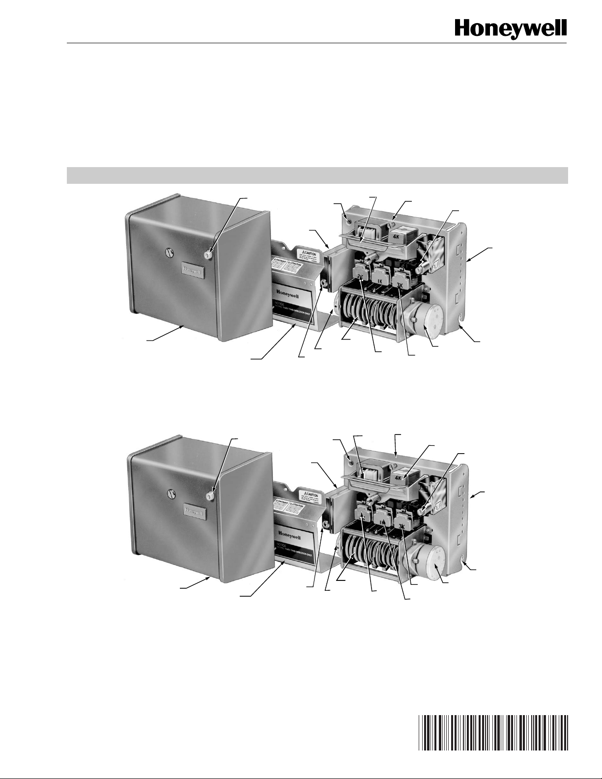
COVER
TIMER DIAL
HANDLE
TIMER
RELAY
2K
CHASSIS RETAINING
SCREW
RELAY
1K
RESET BUTTON
RELAY/TIMER
COVER
TIP JACK
PLUG-IN
FLAME SIGNAL
AMPLIFIER
FLAME SIGNAL
METER JACK
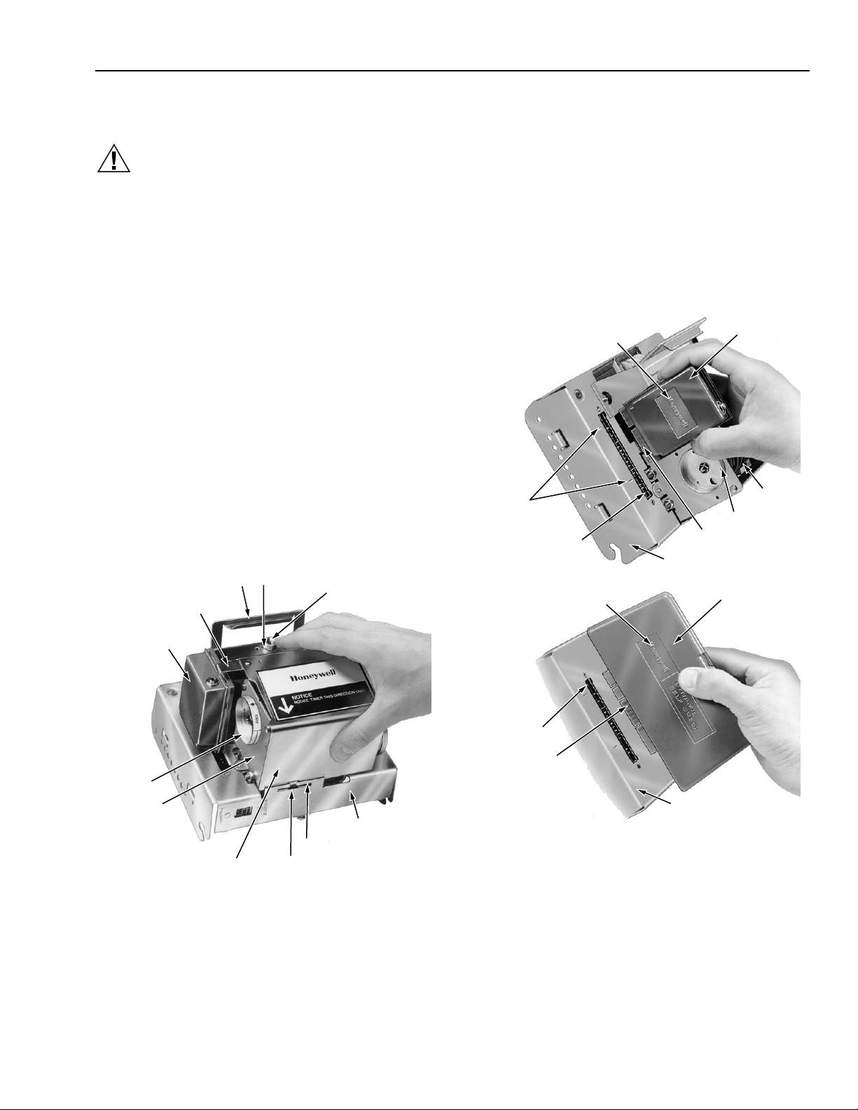
Fig. 1. Components of R4140G and R4140M Programmers.
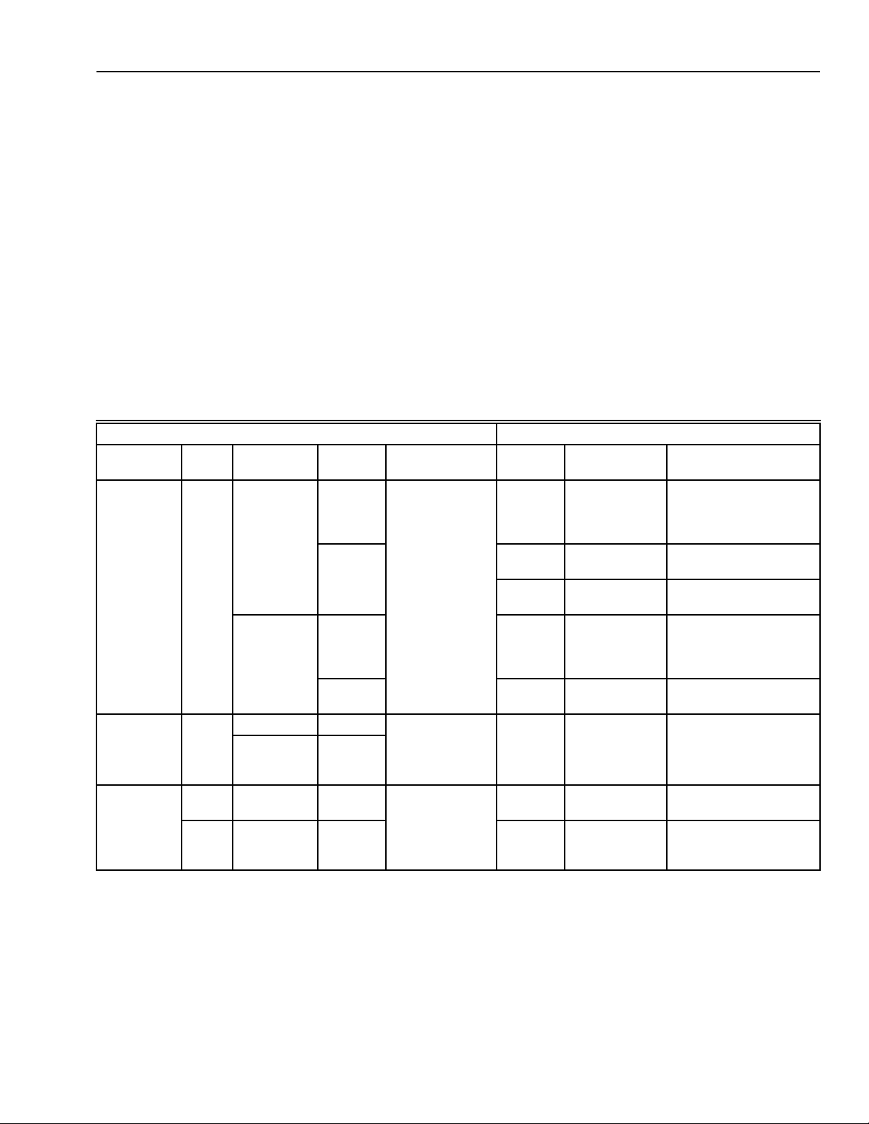
RESET BUTTON
TIP JACK
PLUG-IN
FLAME SIGNAL
AMPLIFIER
HANDLE
CHASSIS RETAINING
SCREW
TIMER
MOTOR
RELAY 4K
SAFETY SWITCH
BUTTON
CHASSIS
HINGE
BRACKET (2)
M10053
SAFETY SWITCH
BUTTON
OPTIONAL HEAVY DUTY
COVER (PART NO.
202050C OR 139695C)
RELAY/TIMER
COVER
Fig. 2. Components of R4140L Programmers.
IMPORTANT
Applications, Features, Specifications (including
dimension drawings), Operation (including
schematics and bar charts), and Wiring Diagrams
are included in these Specifications for models of
the R4140G, L, and M: R4140G—60-2337;
R4140L—60-2339; R4140M—60-2340.
Copyright © 1996 Honeywell Inc. • All Rights Reserved
FLAME SIGNAL
METER JACK
CHASSIS
HINGE
TIMER
TIMER DIAL
RELAY
2K
RELAY
3K
RELAY 1K
TIMER
MOTOR
BRACKET (2)
M7959
Contents
Installation ........................................................................... 2
Checkout ............................................................................. 11
Troubleshooting .................................................................. 18
Service Information ............................................................. 27
Testing and Maintenance .................................................... 28
60-0770-2
Page 2

R4140G, L AND M FLAME SAFEGUARD PROGRAMMING CONTROLS
INSTALLATION
When Installing this Product...
1. Read these instructions carefully. Failure to follow them
could damage the product or cause a hazardous
condition.
2. Check the ratings given in the instructions and on the
product to make sure the product is suitable for your
application.
3. Installer must be a trained, experienced, flame
safeguard control technician.
4. After installation is complete, check out product
operation as provided in these instructions.
CAUTION
1. Disconnect power supply before beginning
installation to prevent electrical shock and
equipment damage.
2. All wiring must be NEC Class 1 (line voltage).
3. Loads connected to the control terminals must
not exceed those listed on the R4140 label or in
the Specifications section of the Specifications for
the R4140G,L or M.
4. Limits and interlocks must be rated to carry and
break current to the ignition transformer, pilot
valve, and main fuel valve(s) simultaneously.
5. All external timers must be listed or component
recognized by authorities having jurisdiction for
the specific purpose for which they are used.
Weather
The R4140 is not designed to be weather tight. If it is installed
outdoors, it must be protected.
Mounting the Wiring Subbase
NOTE: For installation dimensions, see Fig. 1 and 2 in the
Specifications for the R4140G,L or M.
The subbase can be mounted in any position except
horizontally with the knife-blade contacts pointing down.
The standard vertical position (shown in Fig. 5) is
recommended. Any other position decreases the
maximum ambient temperature rating.
Select a location on a wall or instrument panel. (The
0520A Subbase can be mounted directly in the
customer’s cabinet.) Be sure to allow clearances for
servicing and for removal of the R4140.
IMPORTANT
Do not mount the wiring subbase horizontally with
the knife-blade contacts pointing down.
For surface mounting, use the back of the subbase as
a template to mark the four screw locations. Drill the
pilot holes.
Insert the mounting screws and tighten them securely.
Wiring to Subbase
IMPORTANT
1. For on-off gas-fired systems, some authorities
having jurisdiction prohibit the wiring of any limit or
operating contacts in series between the flame
safeguard control and the main fuel valve(s).
2. Do not connect more than two C7012E,F or C7076A
Ultraviolet Flame Detectors (with self-checking
shutter) in parallel to the same terminals.
Use applicable installation instructions provided by the burner
manufacturer in addition to the corresponding instructions
given here. Before putting the system into service, check out
the installation using the procedures in the Checkout section
and any other procedures stipulated by the burner
manufacturer.
Location
Temperature
Install the R4140 where the surrounding temperatures
remain within the Ambient Operating Temperature Ratings in
the Specifications section of the Specifications for the
R4140G,L or M.
Humidity
Install the R4140 where the relative humidity never reaches
the saturation point. Condensation of moisture on the R4140
can cause enough leakage to short the flame signal to ground
and thus prevent the burner from starting.
Vibration
Do not install the R4140 where it could be subjected to
excessive vibration. Vibration shortens the life of the
electronic components.
CAUTION
Make sure the wiring to terminal 7 does not touch any
other terminal, especially terminal 8.
All wiring must comply with all applicable electrical
codes, ordinances, and regulations. Use NEC Class 1
(line voltage) wiring.
For normal installations, use moisture-resistant No. 14
wire suitable for at least 194°F (90°C).
For high temperature installations, use moisture
resistant No. 14 wire, selected for a temperature rating
above the maximum operating temperature, for all but
the ignition and flame detector F leadwires.
a. For the ignition, use Honeywell specification
no. R1061012 Ignition Cable or equivalent. This
wire is rated at 350°F (177°C) for continuous
duty, and up to 500°F (260°C) for intermittent
use. It has been tested to 25,000 volts.
b. For the flame detector F leadwire, use Honeywell
specification no. R1298020 or equivalent. This
wire is rated up to 400°F (204°C) for continuous
duty. It is tested for operation up to 600 volts and
breakdown up to 7500 volts.
IMPORTANT
Do not run high voltage ignition transformer wires in
the same conduit with the flame detector wiring.
For ignition installations in a contaminating
environment, use Honeywell specification no. R1239001
High Tension Ignition Cable or equivalent. This wire is
very resistant to severe conditions of oil, heat, and
corona, and is tested to withstand high voltages up to
60-0770—2
2
Page 3
R4140G, L AND M FLAME SAFEGUARD PROGRAMMING CONTROLS
25,000V rms in a salt bath for one minute without
breakdown. It is rated at 200°F (93°C) for continuous
duty, and up to 350°F (177°C) for intermittent use.
Refer to the appropriate wiring diagram in the
Specifications for the R4140G,L or M. Follow the burner
manufacturer’s wiring diagram, if provided.
Make sure the loads do not exceed the terminal ratings.
Refer to the label on the R4140 or to the Terminal
Ratings in the Specifications section of the
Specifications for the R41406,L or M.
Check the power supply circuit. The voltage and
frequency must match those of the R4140. Do not
connect the R4140 to a circuit that is subjected to line
voltage variations, such as would occur with on-off
switching of heavy loads. A separate power supply
circuit can be required for the flame safeguard control.
Add required disconnect means and overload
protection.
Check all wiring circuits and complete the Static
Checkout in Table 2 before installing the R4140.
Installing the Flame Detector
NOTE: Table 1 lists the flame detection systems available
for use with R4140 Programmers. Make sure you
are using the correct combination of amplifier and
flame detector(s).
Proper flame detector installation is the basis of a safe and
reliable flame safeguard installation. Refer to the instructions
packed with the flame detector and the burner manufacturer’s
instructions. Follow the instructions carefully for the best
possible flame detector application.
Keep the flame signal lead wires as short as possible from
the flame detector to the wiring subbase. Capacitance
increases with Ieadwire length, reducing the signal strength.
The maximum permissible leadwire length depends on the
type of flame detector, leadwire, and conduit. The ultimate
limiting factor in flame signal leadwire length is the signal
current. Refer to Table 4 in the Checkout section.
Table 1. Flame Detection Systems.
Plug-In Flame Signal Amplifiers Applicable Flame Detectors
Type Color
Checking Model
Rectification Green No R7247A 2 to 4 second Gas Rectifying
Self-
Flame Failure
Response Time Fuel Type Models
Holdersa C7004. C7007,
Flame Rods
C7011. Complete
Assemblies: C7005,
C7008, C7009, Q179.
Dynamic
Self-Check
R7247A,
R7247B
R7247B
b
b
Oil Rectifying
Photocells
Gas, Oil,
Coal
Ultraviolet
(Purple Peeper
Gas Rectifying
Flame Rods
c
C7003, C7010, C7013,
C7014.
C7012A or C.
Holdersa: C7004, C7007,
C7011. Complete
Assemblies: C7005,
C7008, C7009, Q179.
R7247C
Infrared Red No R7248A 2 to 4 second
Dynamic
R7248B
d
Gas, Oil,
Coal
Ultraviolet
(Purple Peeper
Gas, Oil, Infrared (Lead
b Coal Sulfide)
C7012E or F.
C7015.
AmpliCheck®
Ultraviolet Purple No R7249A 2 to 4 second Gas, Oil Ultraviolet
C7027, C7035, C7044.
(Minipeeper)
Blue Dynamic
Self-Check
R7476A
d
Gas, Oil,
Coal
Ultraviolet
(Adjustable
C7076.
Sensitivity)
a
Order flame rod separately; see Instructions for the holder.
b
Circuitry tests the flame signal amplifier at least 150 times a minute during burner operation and shuts down the burner if the
amplifier fails.
c
Use only Honeywell part no. 38316 Photocell.
d
Circuitry tests all electronic components in the flame detection system (amplifier and detector) 60 to 240 times a minute during
burner operation and shuts down the burner if the detection system fails.
3
60-0770—2
Page 4

R4140G, L AND M FLAME SAFEGUARD PROGRAMMING CONTROLS
Special Considerations for a C7012E or F
The R4140 provides two sources of power for a C7012E or F
Purple Peeper Ultraviolet Flame Detector (with self-checking
shutter). The power to the black leadwires of a C7012E can
be 120V, 208V, 220V, or 240 Vac, depending on the model of
the detector. The C7012F is available only in a 120V model.
This voltage must match the power supply of the R4140.
After checking all wiring circuits, perform this checkout before
installing the programmer on the subbase. These tests
ensure that the Q520A Wiring Subbase is wired correctly, and
that the external controllers, limits, interlocks, actuators,
valves, transformers, motors, and other devices are operating
properly.
Equipment Required
The power to the white leadwires must be 120 Vac; this is the
power supply for the operation of the self-checking shutter.
The 120V for the shutter is applied automatically at terminal
17 of the R4140 through switching action within the plug-in
R7247C Flame Signal Amplifier.
General Instructions
Using Redundant Parallel C7012E or F Detectors
For a flame that is difficult to sight, using two parallel C7012E
or F Flame Detectors reduces nuisance shutdowns. If only
one of the parallel detectors loses the flame signal, the other
continues to indicate the presence of the flame and keeps the
burner running. A flame simulating failure in either detector
causes the burner to shut down. Two C7012E detectors can
be wired in parallel to the same terminals on any R4140 (if
the voltage ratings match). Two C7012F Detectors can be
wired in parallel only on 120V models. To avoid exceeding the
rating of the solid state shutter switch in the R7247C Flame
Signal Amplifier, do not connect more than two C7012E or F
Detectors in parallel.
Static Checkout (See Table 2)
WARNING
1. Use extreme care while performing these tests;
line voltage is present on most subbase terminals
when power is on.
2. Open the master switch before installing or
removing a test jumper.
3. Be sure to remove the test jumper(s) after
completing each test before continuing to the
next test.
4. Replace all external devices not operating
properly. Do not bypass external devices.
5. Close all manual fuel shutoff valves before
starting these tests.
1. Voltmeter (W136A or equivalent) set on 0 to 300 Vac
scale.
2. Jumper wires (2) of No. 14 wire, insulated, 12 in.
(304.8 mm) long, with alligator clips at both ends.
Perform all applicable tests in Table 2, in the order
listed.
Make sure all manual fuel shutoff valves are closed.
Perform only those tests designated for the specific
programmer model being tested.
Raise the setpoint of the burner controller to simulate a
call for heat.
For each test, open the master switch and install the
jumper wire(s) between the subbase wiring terminals
listed in the Test Jumpers column.
Close the master switch before observing operation.
Read the voltage between the subbase wiring terminals
listed in the Voltmeter column.
If there is no voltage or if operation is abnormal, check
the circuits and external devices as described in the
last column.
Check all wiring in the circuits for correct connections,
tight terminal screws, correct wire, and proper wiring
techniques. Replace all worn or incorrectly sized wires.
쐅 Replace faulty controllers, limits, interlocks, actuators,
valves, transformers, motors, and other devices, as
required.
쐈 Normal operation must be obtained for each required
test before continuing the checkout.
쐉 Be sure to remove the test jumper(s) after completing
each test before continuing on to the next test.
Table 2. Static Tests of External Devices.
Test
No.
R4140
Models
Test
Jumpers Voltmeter
Normal
Operation
If Operation is Abnormal,
Check the Items Listed Below
WARNING
Make sure all manual fuel shutoff valves are closed.
1 All models None L1-L2 Line voltage at terminal L1. 1. Master switch is closed.
2. Power is connected to the master switch.
3. OverIoad protection (fuse, circuit breaker
etc.) has not opened the power line.
2 Models with
Preignition
Interlocks
Models with
Start
Interlocks
60-0770—2
None 4-L2 Line voltage at terminal 4. IMPORTANT
Low fuel pressure limits, if used, could be
open. Bypass them with jumpers for the
remaining Static Tests (if required).
None 16-L2 Line voltage at terminal 16. 1. Limits are closed. If open, determine
cause(s) and correct the condition(s).
2. Burner controller contacts are closed (call for
heat).
4
(Continued)
Page 5
R4140G, L AND M FLAME SAFEGUARD PROGRAMMING CONTROLS
Table 2. Static Tests of External Devices
Test
No.
3 Models with
4 All models L1-8 3-L2 1. Burner motor (fan or blower)
R4140
Models
Preignition
Interlocks
Models with
Start
Interlocks
Test
Jumpers Voltmeter
None 16-L2 Line voltage at terminal 16. 1. Preignition interlocks are closed. If open,
None 4-L2 Line voltage at terminal 4. 1. Start interlock(s), if used, is closed. If open,
starts.
2. Line voltage at terminal 3
within 12 seconds.
Normal
Operation
(Continued).
If Operation is Abnormal,
Check the Items Listed Below
determine cause(s) and correct the
condition(s).
determine cause(s) and correct the
condition(s).
2. If start interlock(s) is not used, jumper is
installed between terminals 4 and 16.
1. Burner motor circuit:
a. Manual switch of burner motor is closed.
b. Burner motor power supply, overload
protection, and starter are OK.
c. Burner motor is OK.
2. Running or Iockout interlocks (including the
Airflow switch) are closed.
WARNING
Make sure all manual fuel shutoff valves are closed.
5 Models with
5 second
ignition
6 All models L1-5 — 1. Ignition spark (if ignition
7 All models L1-6 — Same as test no. 6 for
L1-18 — Ignition spark (if ignition
transformer is connected to
terminal 18).
transformer is connected to
terminal 5).
2. Automatic pilot valve opens
(if connected to terminal 5).
NOTE: Refer to wiring diagram
of the programmer being
tested.
connections to terminal 6. (If
using direct spark ignition,
check the first stage fuel
valve(s) instead of the pilot
valve.)
1. Watch for spark or listen for buzz.
a. Ignition electrodes are clean.
b. Ignition transformer is OK.
1. Watch for spark or listen for buzz:
a. Ignition electrodes are clean.
b. ignition transformer is OK.
2. Listen for click or feel head of valve for
activation.
a. Actuator (if used) is OK.
b. Pilot valve is OK.
Same as test no. 6. (If using direct spark
ignition, check the first stage fuel valve(s)
instead of the pilot valve.)
WARNING
Make sure all manual shutoff valves are closed.
8 All models L1-7 — Automatic main fuel valve(s)
9 All models L1-9 — Alarm (if used) turns on. 1. Alarm is OK.
10 All R4140L
modeIs
11 All R4140G
modeIs
12 All R4140L
models
L1-8 and
10-11
L18 and
14-11
L1-8 and
14-11
13-L2 Firing rate motor drives open;
13-L2 Firing rate motor drives closed;
15-L2 Firing rate motor drives open;
opens. (If using direct spark
ignition on a model with
intermittent pilot/ignition on
terminal 6, check the optional
second stage fuel valve, if
used.)
zero volts at terminal 13 after
motor starts driving open.
line voltage at terminal 13 after
motor closes.
line voltage at terminal 15 after
motor opens.
1. Listen for and observe operation of the main
fuel valve(s) and actuator(s).
2. Valve(s) and actuator(s) are OK.
1. Low Fire switch is open.
2. Firing rate motor and transformer are OK.
1. Low Fire switch is closed.
2. Firing rate motor and transformer are OK.
1. High Fire switch is closed.
2. Firing rate motor and transformer are OK.
(Continued)
5
60-0770—2
Page 6
R4140G, L AND M FLAME SAFEGUARD PROGRAMMING CONTROLS
Test
No.
R4140
Models
13 All R4140L
modeIs
14 All R4140L
models
15 All R4140G
and R4140L
models
16 R4140M
models with
open damper
contacts
17 R4140M
models with
open damper
contacts
Final All models
Table 2. Static Tests of External Devices
Test
Jumpers Voltmeter
L18 and
13-L2 Firing rate motor drives closed;
14-11
line voltage at terminal 13 after
Normal
Operation
motor closes.
L1-15
and
14-11
13-L2 Firing rate motor drives closed;
line voltage at terminal 13 after
motor closes.
12-11 — 1. Raise setpoint of Series 90
Controller—firing rate motor
should drive toward open.
2. Lower setpoint of Series 90
Controller—firing rate motor
should drive toward closed.
L1-10 — If damper control is used,
actuator drives damper open.
L1-8 13-L2 If damper control is used,
spring return drives actuator
and damper closed; line
voltage at terminal 13 after
actuator closes.
CAUTION
After completing these tests, open the master switch and remove all test jumpers from the
subbase terminals. Also remove bypass jumpers from the low fuel pressure limits (if used).
(Continued).
If Operation is Abnormal,
Check the Items Listed Below
1. Low Fire switch is connected between
terminals 8 and 13. If not, proceed to test
no. 14.
2. Low Fire switch is closed.
3. Firing rate motor and transformer are OK.
1. Low Fire switch is connected between
terminals 15 and 13. If not, proceed to test
no. 15.
2. Low Fire switch is closed.
3. Firing rate motor and transformer are OK.
1. Series 90 Controller is OK.
2. Firing rate motor and transformer are OK.
1. Jumper wire is installed between
terminals 11 and 12.
2. Damper actuator is OK.
1. Low Fire switch is closed.
2. Damper actuator is OK.
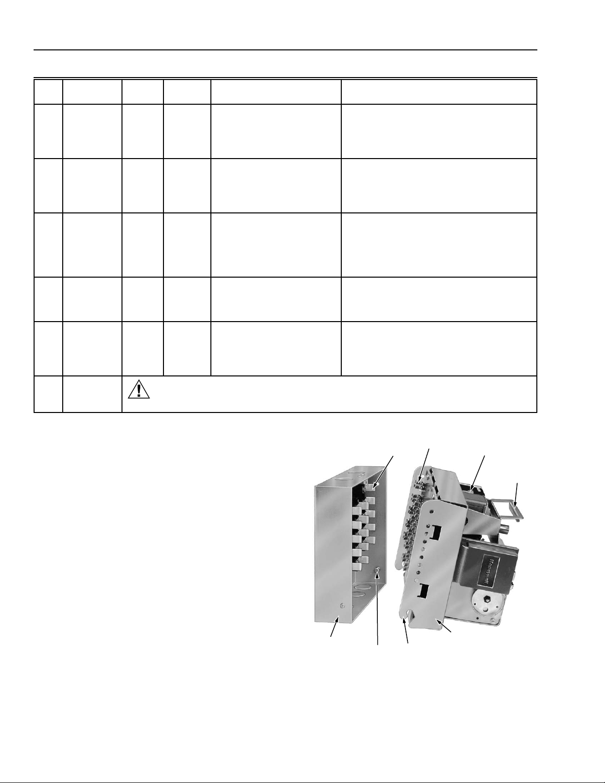
Installing the Programmer (Fig. 3)
Open the master switch.
Make sure no subbase wiring is projecting out beyond
the terminal blocks. Tuck in wiring against the back of
the subbase so it does not interfere with the contacts.
Grasp the handle of the programmer chassis and
engage the chassis hinge brackets with the pivot pins
at the bottom of the subbase.
Swing the chassis inward until the spring connectors
engage the knife-blade contacts. Push in until the
contacts are fully engaged.
Tighten the chassis retaining screw securely.
Removing the Programmer
Open the master switch.
Loosen the chassis retaining screw.
Pull outward on the handle.
Disengage the chassis hinge brackets from the
subbase pivot pins.
WIRING
SUBBASE
KNIFE-BLADE
CONTACTS (20)
PIVOT PIN (2)
SPRING
CONNECTORS
HINGE
BRACKET (2)
CHASSIS
RETAINING
SCREW
PROGRAMMER
CHASSIS
M7965
HANDLE
Fig. 3. Mounting the programmer on the subbase.
60-0770—2
6
Page 7
R4140G, L AND M FLAME SAFEGUARD PROGRAMMING CONTROLS
Removing and Replacing the Relay/Timer
Cover (Fig. 4)
CAUTION
If the programmer is mounted on the subbase, open
the master switch before removing or replacing the
relay/timer cover.
The relay/timer cover must be removed to install a plug-in
flame signal amplifier, to observe relay and timer operation, or
to inspect the contacts.
Removing the Cover
Grasp the relay/timer cover and squeeze until the V-notch
on the cover slides free of the stud on the handle.
Rotate the cover down and out to disengage the two tabs
from the slot in the bottom of the programmer chassis.
Pull out the cover.
Replacing the Cover
Insert the two tabs on the bottom of the cover between
the timer and the programmer chassis and engage
them with the slot in the bottom of the chassis. Make
sure the tabs are not jammed in the slot.
Rotate the cover up and in so the V-notch slides along
the stud on the handle. If the cover does not rotate
easily, the tabs are jammed.
Make sure the spring clip on the cover fits over the
plug-in amplifier.
Push in on the cover until the V-notch snaps into place
on the stud.
V-NOTCH
ON COVER
STUD ON
HANDLE
SPRING CLIP
ON COVER
HANDLE
NOTE: If installing a small amplifier, align its ends with
the two scribe marks alongside the receptacle
on the programmer.
Push in the amplifier until the circuit board is fully
inserted into the receptacle.
Make sure the amplifier is firmly in place, then replace
the relay/timer cover. Make sure the spring clip on the
cover fits over the amplifier.
NOTE: For further information about a self-checking
amplifier, refer to the Instructions packed
with the amplifier (form 60-2358 for an
R7247B or C, form 60-2357 for an R7248B, or
form 95-8270 for an R7476A).
ALIGNMENT
SCRIBE MARKS
FOR SMALL
AMPLIFIER
KEYED
RECEPTACLE
HONEYWELL
MONOGRAM
HONEYWELL
MONOGRAM
PROGRAMMER
CHASSIS
CIRCUIT
BOARD
AMPLIFIER
AMPLIFIER
TIMER
TIMER DIAL
PLUG IN
AMPLIFIER
TIMER
DIAL
TIMER
RELAY/
TIMER COVER
SLOT IN
CHASSIS
TABS (2)
ON COVER
BOTTOM OF
PROGRAMMER
CHASSIS
M7967
Fig. 4. Removing and replacing the relay/timer cover.
Installing a Plug-in Flame Signal Amplifier
(Fig. 5)
Remove the relay/timer cover.
Make sure the Honeywell monogram is on the outside,
then align the circuit board with the keyed receptacle on
the programmer.
KEYED
RECEPTACLE
CIRCUIT
BOARD
PROGRAMMER
CHASSIS
M7961
Fig. 5. Installing a plug-in flame signal amplifier.
Installation Instructions for Special Features
Some TRADELINE® models and international models (rated
for other than 120V, 60 Hz) can have one (or both) of the
following special features.
7
60-0770—2
Page 8

R4140G, L AND M FLAME SAFEGUARD PROGRAMMING CONTROLS
Installing Jumper on Back of Programmer (Fig. 6)
Some R4140G, L, and M models have provisions for
extending the main burner flame-establishing period
(MBFEP) at terminal 6 by installing a jumper on the back of
the programmer. If you are installing one of these models,
A system can be upgraded from on-off to modulating by
replacing an R4140M with an R4140G (Fig. 7). A system can
be upgraded to meet Factory Mutual and Industrial Risk
Insurers (formerly FlA) requirements by replacing an R4140M
or an R4140G with an R4140L (Fig. 8).
determine the required MBFEP. If you need the longer period
provided at terminal 6, install the jumper (included in a bag
assembly with the R4140) between the terminals labeled
JUMPER TO EXTEND MAIN IGN. TRIAL on the back of the
programmer. If you do not need the longer period, leave the
jumper off.
NOTE: Some R4140 models for use in Australia have
jumper terminals on the back of the programmer for
safety shutdown alarm options; these jumpers
cannot be used to extend the MBFEP. These R4140
models are shipped with a jumper link between the
N.O. screw terminals on the back of the
programmer. This results in alarm operation on
Requirements
UL On-Off Start and
UL On-Off (with
2-stage firing)
UL modulating
(with low highlow prepurge)
safety shutdown. N.C. screw terminals are provided
for an external auxiliary safety shutdown circuit.
Refer to the R4140 Specifications for these models.
FM/IRl
modulating (with
low-high-low
JUMPER TO
EXTEND MAIN
5
L1
6
7
8
18
L2
17
16
12
IGN. TRIAL
JUMPER
2
3
4
9
10
prepurge and
proven high fire
purge)
FM Factory Mutual requirements.
IRl Industrial Risk Insurers (formerly FlA) requirements.
UL Underwriters Laboratories Inc. requirements.
Table 3. R4140 Applications.
Application
Interlock
Circuits
Firing Rate
Switching
None R4140M
running
Start,
running, and
low fire
Start or
1-wirea (open
damper
contacts)
4-wire R4140G
pre-ignition,
running, and
low fire
Preignition,
4-wire R4140L
lockout, high
fire, and low
fire
a
Firing rate motor must close by itself (spring-return)
when power is removed.
Applicable
R4140
Several
R4140Ms
G
1
AN R4140L IS SHOWN; R4140G AND R4140M PROGRAMMERS HAVE
FEWER SPRING CONNECTORS. TERMINAL NUMBERS ARE NOT ON
THE PROGRAMMER, BUT ARE SHOWN FOR REFERENCE.
2
INSTALL JUMPER (INCLUDED IN BAG ASSEMBLY) TO OBTAIN THE
LONGER MAIN BURNER FLAME-ESTABLISHING PERIOD AVAILABLE
AT TERMINAL 6.
15
13
14
F
1
11
C8346
Fig. 6. Installing jumper to extend main burner flame-
establishing period.
Upgrading Systems
Conveniently, the R4140 family was developed in models of
varying complexity to allow the user to choose the simplest
programmer that meets their application requirements (Table 3).
IMPORTANT
Before replacing an R4140, make sure the
replacement model has the required:
— prepurge time.
— pilot/ignition timing on terminal 6.
— 5-second ignition on terminal 18 (if required).
— interlock circuits.
— safety features.
— electrical ratings.
— temperature ratings.
— approvals.
60-0770—2
8
Page 9
R4140G, L AND M FLAME SAFEGUARD PROGRAMMING CONTROLS
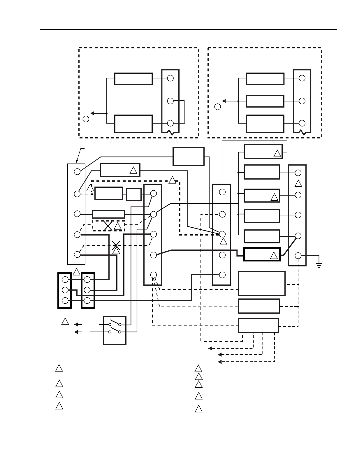
REPLACING AN R4140M WITH AN R4140G
TO
L2
WIRING SUBBASE
TERMINAL STRIP (4)
3
2
4
9
10
HIGH FIRE
COMMON
11
FOR DIRECT SPARK IGNITION (OIL OR GAS)
ON MODELS WITH INTERRUPTED
PILOT/IGNITION ON TERMINAL 6
START OR
PREIGNITION
INTERLOCKS
BURNER
CONTROLLER
120V ALARM
DAMPER
CONTROL
IGNITION
TRANSFORMER
MAIN FUEL
VALVE(S)
1
LIMITS
4
4
L1
L2
12
13
5
JUMPER
6
7
RUNNING
INTERLOCKS
(INCL. AIRFLOW
SWITCH)
2
FOR DIRECT SPARK IGNITION (OIL OR GAS)
ON MODELS WITH INTERMITTENT
PILOT/IGNITION ON TERMINAL 6
IGNITION
TRANSFORMER
TO
L2
18
17
16
2
15
1ST STAGE
FUEL VALVE
2ND STAGE
FUEL VALVE
(OPTIONAL)
5 SECOND IGNITION
(EARLY SPARK
TERMINATION)
10 SECOND
INTERRUPTED
PILOT/IGNITION
PILOT/IGNITION
MAIN FUEL
VALVES(S)
BURNER MOTOR
(BLOWER)
LOW FIRE
SWITCH
7
9
6
5
6
7
5
8
6
7
8
G
5
B
R
W
SERIES 90
CONTROLLER
1
120V, 60 HZ
POWER
SUPPLY
1
LEAVE INTERLOCKS CONNECTED BETWEEN TERMINALS 4 AND 16. (IF
INTERLOCKS ARE NOT USED, INSTALL A JUMPER WIRE BETWEEN
TERMINALS 4 AND 16.)
2
IF THE R4140G REPLACEMENT MODEL HAS "START" INTERLOCKS,
CONNECT THE BURNER CONTROLLER TO TERMINAL 16.
3
IF THE R4140G REPLACEMENT MODEL HAS "PREIGNITION" INTERLOCKS,
CONNECT THE BURNER CONTROLLER TO TERMINAL 4.
4
IF REPLACING AN R4140M WITH OPEN DAMPER CONTACTS, REMOVE
DAMPER CONTROL FROM TERMINALS 10 AND L2, AND REMOVE JUMPER
WIRE FROM TERMINALS 11 AND 12.
B
R
W
L1 (HOT)
L2
MODULATE
LOW FIRE
SERIES 90
FIRING RATE
MOTOR
MASTER
SWITCH
F
Fig. 7. Sample block diagram of field wiring for replacing an R4140M with an R4140G.
14
BLUE
BLUE
WHITE
WHITE
L2
L1
L2
5
ADD SERIES 90 CONTROLLER AND SERIES 90 FIRING RATE MOTOR.
5 SECOND IGNITION IS NOT AVAILABLE ON SOME MODELS.
6
REFER TO SPECIFICATIONS OF THE SPECIFIC R4140G MODEL TO
7
DETERMINE THE PILOT/IGNITION TIMING AVAILABLE ON TERMINAL 6.
FOR DIRECT SPARK IGNITION (OIL OR GAS), CONNECT THE
8
IGNITION TRANSFORMER AND FUEL VALVE(S) AS SHOWN IN THE
APPROPRIATE INSET.
9
ADD LOW FIRE SWTICH (IF NOT ALREADY CONNECTED).
RECTIFYING FLAME
ROD, RECTIFYING
PHOTOCELL, OR INFRARED (LEAD SULFIDE)
FLAME DETECTOR
C7027A, C7035A, OR
C7044A ULTRAVIOLET
FLAME DETECTOR
C7012A,C,E,F OR
C7076A ULTRAVIOLET
FLAME DETECTOR
BLACK
BLACK
WHITE
YELLOW
C8347
9
60-0770—2
Page 10
R4140G, L AND M FLAME SAFEGUARD PROGRAMMING CONTROLS
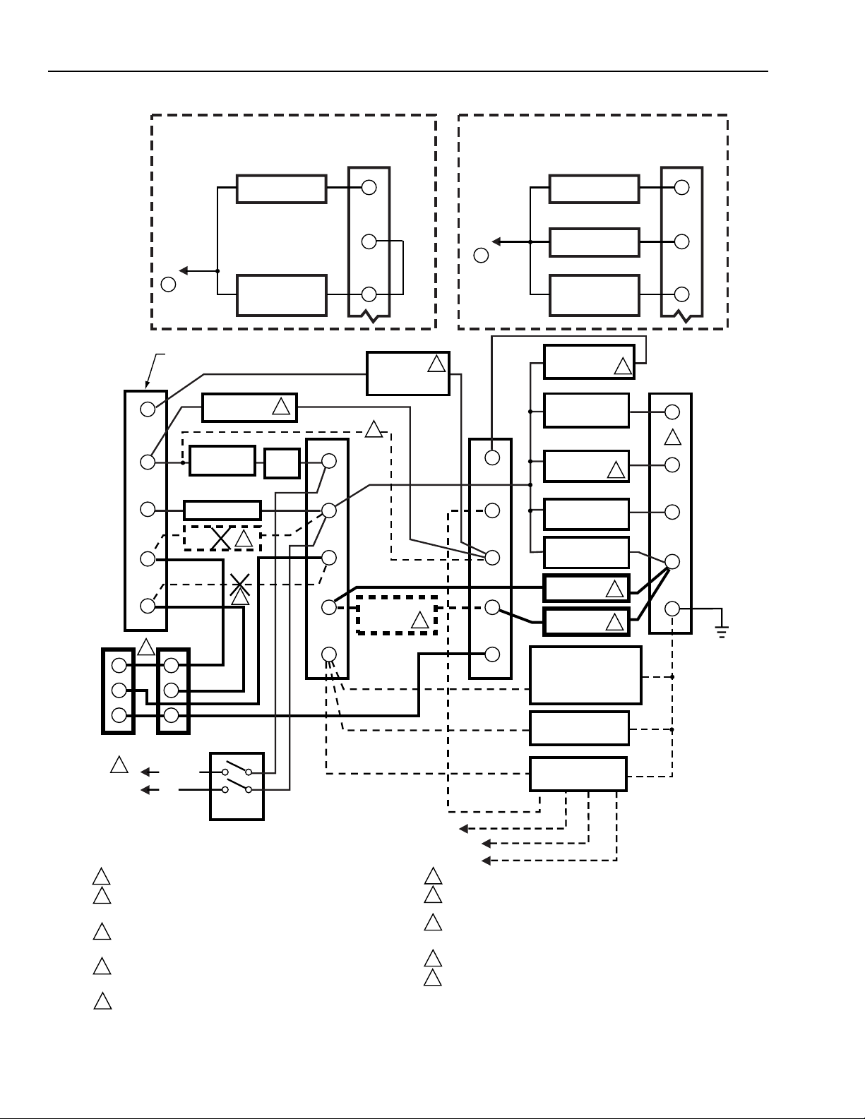
REPLACING AN R4140M OR G WITH AN R4140L
FOR DIRECT SPARK IGNITION (OIL OR GAS)
ON MODELS WITH INTERRUPTED
PILOT/IGNITION ON TERMINAL 6
IGNITION
TRANSFORMER
TO
L2
WIRING SUBBASE
TERMINAL STRIP (4)
HIGH FIRE
COMMON
B
R
W
PREIGNITION
INTERLOCKS
BURNER
CONTROLLER
120V ALARM
DAMPER
CONTROL
MODULATE
LOW FIRE
SERIES 90
FIRING RATE
MOTOR
3
4
9
10
11
5
B
R
W
SERIES 90
CONTROLLER
1
120V, 60 HZ
POWER
SUPPLY
1
LEAVE INTERLOCKS CONNECTED BETWEEN TERMINALS 3 AND 16.
LEAVE INTERLOCKS CONNECTED BETWEEN TERMINALS 4 AND 16.
2
IF THERE IS A JUMPER WIRE BETWEEN TERMINALS 14 AND 16, REMOVE
IT AND INSTALL INTERLOCKS.
IF REPLACING MODEL WITH "START" INTERLOCKS, DISCONNECT THE
3
BURNER CONTROLLER FROM TERMINAL 16 AND CONNECT IT TO
TERMINAL 4.
4
IF REPLACING AN R4140M WITH OPEN DAMPER CONTACTS, REMOVE
DAMPER CONTROL FROM TERMINALS 10 AND L2, AND REMOVE
JUMPER WIRE FROM TERMINALS 11 AND 12.
5
IF REPLACING AN R4140M, ADD SERIES 90 CONTROLLER AND SERIES 90
FIRING RATE MOTOR.
L1 (HOT)
L2
4
4
MASTER
SWITCH
MAIN FUEL
VALVE(S)
2
LIMITS
L1
L2
12
13
F
5
JUMPER
6
7
LOCKOUT
INTERLOCKS
(INCL. AIRFLOW
SWITCH)
3
ALTERNATE
LOW FIRE
SWITCH
FOR DIRECT SPARK IGNITION (OIL OR GAS)
ON MODELS WITH INTERMITTENT
PILOT/IGNITION ON TERMINAL 6
IGNITION
TRANSFORMER
TO
L2
1
18
17
16
15
9
14
BLUE
BLUE
WHITE
WHITE
L2
6
5 SECOND IGNITION IS NOT AVAILABLE ON SOME MODELS.
7
REFER TO SPECIFICATIONS OF THE SPECIFIC R4140L MODEL TO
DETERMINE THE PILOT/IGNITION TIMING AVAILABLE ON TERMINAL 6.
8
FOR DIRECT SPARK IGNITION (OIL OR GAS), CONNECT THE
IGNITION TRANSFORMER AND FUEL VALVE(S) AS SHOWN IN THE
APPROPRIATE INSET.
9
ADD LOW FIRE SWITCH (IF NOT ALREADY CONNECTED).
ADD HIGH FIRE SWITCH.
10
BLACK
L1
BLACK
L2
1ST STAGE
FUEL VALVE
2ND STAGE
FUEL VALVE
(OPTIONAL)
5 SECOND IGNITION
(EARLY SPARK
TERMINATION)
10 SECOND
INTERRUPTED
PILOT/IGNITION
PILOT/IGNITION
MAIN FUEL
VALVES(S)
BURNER MOTOR
(BLOWER)
LOW FIRE
SWITCH
HIGH FIRE
SWITCH
RECTIFYING FLAME
ROD, RECTIFYING
PHOTOCELL, OR INFRARED (LEAD SULFIDE)
FLAME DETECTOR
C7027A, C7035A, OR
C7044A ULTRAVIOLET
FLAME DETECTOR
C7012A,C,E,F OR
C7076A ULTRAVIOLET
FLAME DETECTOR
7
9
10
6
WHITE
YELLOW
5
6
7
5
8
6
7
8
G
C8349
60-0770—2
Fig. 8. Sample block diagram of field wiring for replacing an R4140M or G with an R4140L.
10
Page 11

R4140G, L AND M FLAME SAFEGUARD PROGRAMMING CONTROLS
CHECKOUT
WARNING
FIRE OR EXPLOSION HAZARD
CAN CAUSE PROPERTY DAMAGE,
SEVERE INJURY OR DEATH.
Do not manually operate relays.
WARNING
Do not allow fuel to accumulate in the combustion
chamber. If fuel is allowed to enter the chamber for
longer than a few seconds without igniting, an
explosive mixture could result. It is recommended
limiting the trial for pilot to ten seconds, and limiting
the attempt to light the main burner to five seconds. In
any case, do not exceed the normal lightoff time
specified by the burner manufacturer; close the
manual fuel shutoff valves if the flame is not burning
at the end of the specified time.
CAUTION
1. Use extreme care while testing the programmer;
line voltage is present on most contacts when
power is on.
2. Open the master switch before removing the
programmer from the subbase, before reinstalling
the programmer, before installing or removing
any jumpers, and before making any
adjustments.
3. Make sure all manual fuel shutoff valves are
closed before starting the Initial Lightoff Check
and the Pilot Turndown Test.
4. If low fuel pressure limits are bypassed for any of
the tests, make sure you remove the jumpers
from these limits before putting the system into
service.
5. Do not put the system into service until you have
satisfactorily completed all applicable tests
described in this Checkout section and any
others required by the burner manufacturer.
IMPORTANT
a. If the system fails to perform properly, note the point
at which trouble occurs and refer to the
Troubleshooting section.
b. Before you reset the lockout switch, wait at least one
minute to allow the heater to cool.
c. Repeat ALL required Checkout tests after all
adjustments are made. ALL tests must be satisfied
with the flame detector(s) in its FINAL position.
Equipment Required
1. Voltmeter (Honeywell W136A or equivalent) with 0 to
300 Vac scale.
2. Microammeter (Honeywell W136A or equivalent) with
0 to 25 microampere range and SPL scale with
damping.
3. Part no. 196146 Meter Connector Plug or equivalent.
4. Jumper wires (2) of No. 14 wire, insulated, 12 in.
(304.8 mm) long, with alligator clips at both ends.
5. Watch or clock with second hand.
6. Manometer (or pressure gauge) to measure pilot gas
pressure.
7. Thermometer or thermocouple to measure temperature
at the flame detector(s).
8. Orifice plates (aperture disks) or filters, as necessary, to
adjust sensitivity of flame detector(s).
Checkout Summary
The following list summarizes the checkout tests required for
each type of installation. Instructions for each test are
included in this section; also consult the burner installation
instructions.
• Preliminary Inspection—all installations.
• Flame Signal Measurement—all installations.
• Initial Lightoff Check for Proved Pilot—all installations
using a pilot.
• Initial Lightoff Check for Direct Spark Ignition of Oil—oil
burners not using a pilot.
• Pilot Turndown Test—all installations using a pilot.
• Ignition Interference Test—all installations using flame rods.
• Hot Refractory Saturation Test—all installations using
infrared (lead sulfide) flame detectors.
• Hot Refractory Hold-in Test—all installations using rectifying
photocells or infrared (lead sulfide) flame detectors.
• Ultraviolet Response Tests—all installations using
ultraviolet flame detectors.
• Flame Signal with Hot Combustion Chamber—all
installations.
• Safety Shutdown Tests—all installations.
Refer to Fig. 1 or 2 for locations of component parts, and to
Fig. 7 or 8 for terminal locations.
Preliminary Inspection (All Installations)
Perform this inspection to avoid common problems. Make
certain that:
Wiring connections are correct and all terminal screws
are tight.
Voltage rating of the flame detector(s) matches the
voltage rating of the R4140.
Flame detector(s) is clean, installed and positioned
properly. Consult the appropriate Instructions.
Correct combination of amplifier and flame detector(s)
is used. Refer to Table 1 in the Installation section.
Spring clip on relay/timer cover is holding the plug-in
flame signal amplifier securely in the receptacle.
Burner is completely installed and ready to fire (consult
burner manufacturer’s instructions); fuel lines are
purged of air.
Combustion chamber and flues are clear of fuel and
fuel vapor.
Power is connected to the system disconnect switch
(master switch).
Lockout switch is reset (push in lockout switch reset
button, see Fig. 1 or 2).
쐅 Timer switch is in NORM position (Fig. 9).
쐈 The large dot between PURGE and PREPURGE on the
timer dial is at the index notch (Fig. 14). If not, manually
rotate the timer dial to the proper position. Rotate the
timer only in the direction shown by the arrow on the
relay/timer cover.
NOTE: The timer dial on the R4140L1030 cannot be
rotated manually, and there is no arrow on its
relay/ timer cover.
11
60-0770—2
Page 12

R4140G, L AND M FLAME SAFEGUARD PROGRAMMING CONTROLS
쐉 All limits and interlocks are reset.
씈 If you are installing a TRADELINE® model or an
international model (rated for other than 120V, 60 Hz)
check for one (or both) of these special features.
a. If the R4140 has provisions for extending the
main burner flame-establishing period (MBFEP)
at terminal 6, make sure the jumper is, or is not,
installed on the back of the programmer,
depending on the MBFEP desired.
RELAY/TIMER
COVER
INDEX NOTCH
PLUG-IN
AMPLIFIER
DOT ON
TIMER DIAL
TIMER
BOTTOM OF
PROGRAMMER
CHASSIS
W136A
TEST METER
RED (+) METER LEAD
SELECTOR
SWITCH
BLACK (-) METER LEAD
PLUG IN FLAME
SIGNAL AMPLIFIER
PLUG
196146 METER
CONNECTOR
PLUG
RED SPADE TIP
BLACK SPADE TIP
FLAME SIGNAL
METER JACK
M6424
Fig. 10. Measuring the flame signal.
Read the average stable current. For an R7247B or C
or an R7476A Dynamic Self-Check Amplifier, disregard
the peaks due to self-checking operation. The red
flame-indicating lamp on a self-checking amplifier
should blink:
— about 2-1/2 to 4 times a second on an R7247B.
— about 1 to 2 times a second on an R7247C or
R7476A.
— at the same rate that the flame is flickering (can
be as high as 20 times a second) on an R7248B.
M7966
TIMER SWITCH
Fig. 9. Location of timer switch and position of timer dial
at startup.
Flame Signal Measurement (Fig. 10 and
Table 4) for All Installations
Measure the flame signal at the appropriate times defined in the
following checkout tests. Read the flame signal in microamps at
the meter jack on the plug-in flame signal amplifier.
Use a Honeywell W136A Test Meter. (If a W136A is not
available, a microammeter with a 0 to 25 uA dc range
can be used.)
Set the selector switch on the test meter to:
— 25 uA for all standard amplifiers (R7247A, R7248A,
and R7249A) or for an R7248B Dynamic AmpliCheck® Infrared Amplifier or
— SPL for an R7247B or C or an R7476A Dynamic
Self-Check Amplifier. (If the test meter is not a
W136A, shunt the 0 to 25 uA dc range with a
50 microfarad capacitor.)
Use a part no. 196146 Meter Connector Plug, ordered
separately. Connect the red spade tip to the red (+)
meter lead and the black spade tip to the black (-)
meter lead.
Insert the plug into the flame signal meter jack and
allow a few seconds for the meter reading to stabilize.
If the lamp is on or off continuously while reading the flame
signal, replace the amplifier.
The meter reading must be as specified in Table 4 after
all tests are complete and all adjustments are made.
If the signal is unstable or less than the minimum acceptable
current, check the flame detector installation and circuitry.
Check the supply voltage at terminals L1-L2 on the
wiring subbase. Make sure the master switch is closed,
connections are correct, and the power supply is of the
correct voltage and frequency.
Check the detector wiring for defects including:
— incorrect connections.
— wrong type or size of wire.
— deteriorated wire.
— open circuits.
— short circuits.
— leakage paths caused by moisture, soot, or
accumulated dirt.
For a flame rod, make sure:
— there is enough ground area.
— the flame rod is properly located in the flame.
— temperature at the flame rod insulator is no
greater than 500°F (260°C).
— ignition interference is not present (see Ignition
Interference Test section).
60-0770—2
12
Page 13

R4140G, L AND M FLAME SAFEGUARD PROGRAMMING CONTROLS
For all other detectors, clean the detector lens, filter,
NOTE: Low fuel pressure limits, if used, could be open. If
viewing window, and inside of the sight pipe, as
applicable.
For a C7012A,C,E or F Purple Peeper Ultraviolet Flame
Detector, replace the 113236 and 115330 Electron
Tubes, unless the detector is a solid state model.
With the burner running, check the temperature at the
detector. If it exceeds the detector’s maximum rated
temperature:
— add additional insulation between the wall of the
combustion chamber and the detector,
— add a shield or screen to reflect radiated heat
away from the detector, or
— add cooling. (Refer to Sight Pipe Ventilation in the
Instructions for the detector.)
Make sure that the flame adjustment is not too lean.
Make sure the detector is properly sighting the flame.
If necessary, resight or reposition the detector.
If you cannot obtain proper operation, replace the plug-in
amplifier. If you continue to be unable to obtain proper
operation, replace the flame detector.
Initial Lightoff Check for Proved Pilot (All
Installations Using a Pilot)
Perform this check on all installations using a pilot. It should
immediately follow the preliminary inspection.
so, bypass them with jumpers during this check.
Open the master switch.
Make sure the manual main fuel shutoff valve(s) is
closed. Open the manual pilot shutoff valve. If the pilot
takeoff is downstream from the manual main fuel
shutoff valve, make sure the main fuel is shut off just
upstream from the burner inlet, or disconnect power
from the automatic main fuel valve(s).
Close the master switch and start the system with a call
for heat (raise the setpoint of the burner controller). The
burner motor (blower) should run, the programmer
timer should start, and prepurge should begin.
Let the timer dial advance through PREPURGE. When
the IGN part of the dial is opposite the index notch,
spark should occur and the pilot should ignite. If it
ignites, proceed to step .
If the pilot flame is not established in ten seconds,
safety shutdown occurs in about one-half minute. Let
the timer complete its revolution and stop.
Wait about one minute, reset the lockout switch, and let
the system recycle once. If the pilot still does not ignite,
make the following ignition/pilot adjustments:
a. Open the master switch and remove the
programmer from the subbase.
Table 4. Flame Signal.
Flame Detector Flame Signal Amplifier
Minimum Acceptable
Steady Currenta (uA)
Maximum Current
Expected (uA)
Rectifying Flame Rod R7247A (Green) 2 5
R7247B (Green Self Check)
Rectifying Photocell R7247A Green 2 5
R7247B Green Self Check
b
b
1-1/4 2-12
c
1-1/4 2-12
C7012A,C Ultraviolet (Purple Peeper) R7247A (Green) 2 6
R7247B (Green Self Check)
C7012E,F Ultraviolet (Purple Peeper)
e
R7247C (Green Self Check)
C7015A Infrared (Lead Sulfide Cell) R7248A (Red) 2-1/4
R7248B (Red Ampli-Check)
C7027A, C7035A, or C7044A Ultraviolet
R7249A (Purple) 3-1/2 7-1/2
b
d
b
24
e
2
3-1/2
f
f
7
5
5
(Minipeeper)
C7076A Ultraviolet (Adjustable Sensitivity)eR7476A (Blue Self Check)
a
This minimum or stronger signal is easily obtained when the detector is correctly installed and positioned to sense flame
properly.
b
When using an R7247B or an R7248B, circuitry tests the flame signal amplifier at least 150 times a minute during burner
operation and shuts down the burner if the
c
Do not permit signal to exceed five microamperes because it shortens the photocell life. Reduce the signal by using orifice
plates (aperture disks) or filters, as necessary.
d
If using an R7247C or an R7476A, circuitry tests all electronic components in the flame detection system (amplifier and
detector) 60 to 240 times a minute during burner operation and shuts down the burner if the detection system fails.
e
Shutter operation of the C7012E or F or C7076A causes fluctuations in the current reading. Read the average stable current,
disregarding the peaks.
f
The lead sulfide cells are available in two ranges of sensitivity: 104662B is lowest and 104662D is highest sensitivity. If a
This current must be obtained before completing checkout.
amplifier
fails.
d
2-1/2
e
5-1l2
sufficiently strong signal cannot otherwise be obtained, try a different cell of the same range. If necessary, substitute a cell of
higher sensitivity.
13
60-0770—2
Page 14

R4140G, L AND M FLAME SAFEGUARD PROGRAMMING CONTROLS
b. On the subbase, jumper terminal L1 to the
ignition terminal (5, 6, or 18). Refer to the
appropriate wiring diagram to determine the
proper terminal. Disconnect the leadwire to the
pilot valve if it is connected to the same terminal.
c. Close the master switch only to energize the
ignition transformer.
d. If the ignition spark is not strong and continuous,
open the master switch and adjust the ignition
electrode spark gap setting to the manufacturer’s
recommendation.
e. Make sure the ignition electrodes are clean.
f. Close the master switch and observe the spark.
g. Once a continuous spark is obtained, open the
master switch and add a jumper on the subbase
from terminal L1 to the pilot terminal (5 or 6).
Reconnect the leadwire from the pilot valve if it
was disconnected in step b.
h. Close the master switch to energize both the
ignition transformer and the pilot valve.
I. If the pilot does not ignite and if the ignition spark
is still continuous, adjust the pilot gas pressure
regulator until a pilot is established.
j. When the pilot ignites properly and stays ignited,
open the master switch and remove the jumper(s)
from terminals L1-5, L1-6, or L1-18 of the
subbase.
k. Check for adequate fuel line bleeding.
l. Reinstall the programmer on the subbase, reset
the lockout switch, and close the master switch.
When the pilot ignites, measure the flame signal. If
necessary, adjust the flame or detector to give a proper
flame signal.
Recycle the system to recheck lightoff and the pilot
flame signal.
When the MAIN part of the timer dial is opposite the
index notch, make sure the automatic main fuel
valve(s) opens; then smoothly open the manual main
fuel shutoff valve (and manually opened safety shutoff
valve, if used) and watch for main burner flame ignition.
When the main burner flame is established, proceed to
step 씊.
NOTE: This step requires two people—one to open
the manual valve(s) and one to watch for
ignition.
쐅 If the main burner flame is not established within five
seconds, or within the normal lightoff time specified by
the burner manufacturer, close the manual main fuel
shutoff valve(s) and open the master switch.
쐈 Purge the combustion chamber to remove any
unburned fuel. Check all burner adjustments.
쐉 Wait about three minutes. Reset the lockout switch,
close the master switch, and let the programmer
recycle to MAIN. Smoothly open the manual fuel shutoff
valve(s) and try lightoff again. The first attempt may
have been required to purge the lines and bring
sufficient fuel to the burner.
NOTE: This step requires two people—one to open
the manual valve(s) and one to watch for
ignition.
씈 If the main burner flame is not established within five sec-
onds, or within the normal lightoff time specified by the
burner manufacturer, close the manual main fuel shutoff
valve(s) and open the master switch. Check all burner
adjustments.
씉 Repeat steps 쐈 through 씈 to establish the main
burner flame.
씊 When the main burner flame is established, the timer
dial advances to the end of MAIN and stops. Make
burner adjustments for flame stability and input rating.
씋 Shut down the system by lowering the setpoint of the
burner controller. Make sure the main burner flame
goes out. If using an intermittent pilot, make sure the
pilot flame goes out. Make sure all automatic fuel
valves close.
씌 If used, remove the bypass jumpers from the low fuel
pressure limits.
씍 Restart the system by raising the setpoint of the burner
controller. Observe that the pilot is established during
IGN and the main burner flame during MAIN, within the
normal lightoff time specified by the burner
manufacturer.
씎 Measure the flame signal. Continue to check for the
proper signal (Table 4) through the MAIN part of the
timer dial, and into the Run period after the timer stops.
Check the signal at both high and low firing rate
positions and while modulating, if applicable.
씏 Run the burner through another sequence, observing
the flame signal for:
— pilot alone (unless using direct spark ignition)
— pilot and main burner flame together, and
— main burner flame alone (unless monitoring an
intermittent pilot).
Also observe the time to light the main burner.
IMPORTANT
Make sure all readings are in the required ranges
before proceeding.
Initial Lightoff Check for Direct Spark
Ignition of Oil (Oil Burners not Using a Pilot)
This check applies for oil burners not using a pilot. It should
immediately follow the preliminary inspection.
Refer to the appropriate sample block diagram of field wiring
in the R4140 Specifications for the ignition transformer and
fuel valve(s) hookup.
NOTE: Low fuel pressure limits, if used, could be open. If
so, bypass them with jumpers during this check.
Open the master switch.
Complete the normal ready-to-fire checkout of the oil
supply and equipment as recommended by the burner
manufacturer.
Close all manual fuel shutoff valves. Check that the
automatic fuel valves are closed. Make sure oil is not
entering the combustion chamber.
Close the master switch and start the system with a call
for heat (raise the setpoint of the burner controller). The
burner motor (blower) should run, the programmer
timer should start, and prepurge should begin.
60-0770—2
14
Page 15

R4140G, L AND M FLAME SAFEGUARD PROGRAMMING CONTROLS
Let the timer dial advance through PREPURGE. When
the IGN part of the dial is opposite the index notch,
watch for ignition spark and listen for the click of the
first stage oil solenoid. (If spark does not occur or the
first stage oil valve does not open, refer to Symptom E
in Table 5 in the Troubleshooting section.)
Let the programmer complete its revolution and stop.
Open the manual first stage oil valve.
Reset the lockout switch and recycle the programmer
through PREPURGE.
When the IGN part of the timer dial is opposite the
index notch, watch for the first stage burner flame to be
established. If it is, proceed to step 씊.
쐅 If the first stage burner flame is not established within
five seconds, or within the normal lightoff time specified
by the burner manufacturer, close the manual first
stage oil valve and open the master switch.
쐈 Purge the combustion chamber to remove any
unburned oil; then check all burner adjustments.
쐉 Wait about three minutes. Close the master switch,
open the manual first stage oil valve, and try lightoff
again. The first attempt may have been required to
purge the lines and bring sufficient oil to the burner.
씈 If the first stage burner flame is not established within
five seconds, or within the normal lightoff time specified
by the burner manufacturer, close the manual first
stage oil valve and open the master switch.
씉 If necessary, repeat steps 쐈 through 씈 to establish the
first stage burner flame. Then proceed to step 씊.
씊 When the first stage burner flame is established, the
timer dial advances to the end of MAIN and stops.
Make burner adjustments for flame stability and input
rating. If a second stage is used, make sure the
automatic second stage oil valve opened.
씋 Shut down the system by lowering the setpoint of the
burner controller. Make sure the burner flame goes out
and all automatic oil valves close.
씌 If used, remove the bypass jumpers from the low fuel
pressure limits.
씍 If a second stage is used, check the lightoff as follows;
otherwise, proceed to step 씎.
a. Open the manual second stage oil valve.
b. Restart the system by raising the setpoint of the
burner controller.
c. When the first stage burner flame is established,
watch for the automatic second stage oil valve to
open. Observe that the second stage lights off
properly.
d. Make burner adjustments for flame stability and
input rating.
e. Shut down the system by lowering the setpoint of
the burner controller. Make sure the burner
flames go out and all automatic oil valves close.
f. Proceed to step 씎.
씎 Restart the system by raising the setpoint of the burner
controller. Observe that the burner flame is established
during IGN, within the normal lightoff time specified by
the burner manufacturer.
씏 Measure the flame signal. Continue to check for the
proper signal (Table 4) through the MAIN part of the
timer dial and into the Run period after the timer stops.
Check the signal at both the high and the low firing rate
positions and while modulating, if applicable. Any
pulsating or unsteady readings require further
adjustments.
IMPORTANT
Make sure all readings are in the required ranges
before proceeding.
Pilot Turndown Test (All Installations using
a Pilot)
Perform this check on all installations using a pilot. It should
immediately follow the initial lightoff check. The purpose of
this test is to ensure that the main burner can be lighted by
the smallest pilot flame that can hold in the 2K (flame) relay.
Clean the flame detector(s) to ensure it can detect the
smallest acceptable pilot flame.
NOTE: Low fuel pressure limits, if used, could be open. If
so, bypass them with jumpers during this test.
Open the master switch.
Close the manual main fuel shutoff valve(s).
Connect a manometer (or pressure gauge) to measure
pilot gas pressure during the turndown test.
Open the manual pilot shutoff valve.
Close the master switch and start the system with a call
for heat (raise the setpoint of the burner controller). The
burner motor (blower) should run, the programmer
timer should start, and prepurge should begin.
When the IGN area of the timer dial is opposite the
index notch, set the timer switch to the TEST position to
stop the timer. Relay 2K should pull in when the pilot
ignites.
NOTE: If the timer does not stop, recycle the
programmer and set the timer switch as soon
as the beginning of the IGN area of the timer
dial reaches the index notch.
IMPORTANT
You have only six seconds to stop the timer after the
ignition starts.
Turn down the pilot pressure very slowly, reading the
manometer (or gauge) as it drops. Stop instantly when
relay 2K drops out. Note the pressure at the dropout
point. The pilot is at the turndown position. Immediately,
turn up the pilot pressure until relay 2K pulls in again.
NOTE: With the timer stopped in this position, the
lockout switch heats when 2K is not pulled in.
If 2K is out for a total of about one-half minute,
safety shutdown occurs.
Repeat step to verify the pilot gas pressure reading
at the exact point of relay 2K dropout.
Increase the pilot pressure immediately to pull in 2K,
and then turn it down slowly to obtain a pressure
reading just above the dropout point.
쐅 Set the timer switch to the NORM position and let the
timer proceed. When the MAIN area of the timer dial
reaches the index notch, make sure the automatic main
fuel valve(s) opens; then smoothly open the manual
main fuel shutoff valve (and manually opened safety
shutoff valve, if used) and watch for main burner
ignition. If the main burner flame is established,
proceed to step 씌.
15
60-0770—2
Page 16

R4140G, L AND M FLAME SAFEGUARD PROGRAMMING CONTROLS
NOTE: This step requires two people—one to open the
manual valve(s) and one to watch for ignition.
쐈 If the main burner flame is not established within five
seconds, or within the normal lightoff time specified by
the burner manufacturer, close the manual main fuel
shutoff valve(s) and open the master switch.
쐉 Purge the combustion chamber to remove any
unburned fuel. Check all burner adjustments.
씈 Wait about three minutes. Reset the lockout switch (if
tripped), close the master switch, and let the
programmer recycle to MAIN. Repeat steps 쐅 and 쐈
(try lightoff again).
씉 If the second attempt is unsuccessful, adjust the flame
detector position so that a larger pilot is required to hold
in flame relay 2K. This may require relocating the flame
detector to sense farther out on the pilot flame, or
adding an orifice plate.
씊 Measure the pilot flame signal after adjusting the flame
detector to make sure it is stable and above the
minimum (see Table 4).
씋 Repeat steps through 씊 until the main burner
positively lights with the pilot flame just holding in flame
relay 2K.
씌 Repeat the lightoff of the main burner several times
(steps through 쐅) with the pilot at turndown.
씍 When the main burner lights reliably with the pilot at
turndown, disconnect the manometer (or gauge) and
turn up the pilot to normal.
씎 If used, remove the bypass jumpers from the low fuel
pressure limits.
씏 Run the system through another cycle to check for
normal operation.
Ignition Interference Test (All Flame Rods)
Test to make certain that a false signal from a spark ignition
system is not superimposed on the flame signal.
Ignition interference can subtract from (decrease) or add to
(increase) the flame signal. If it decreases the flame signal
enough, it causes safety shutdown (relay 2K does not pull in
and the programmer acts as though the pilot or main burner, if
using direct spark ignition, was not ignited). If it increases the
flame signal, it could cause relay 2K to pull in when the true
flame signal is below the minimum acceptable value.
To Test for Interference
Start the burner and measure the flame signal with both
ignition and pilot (or main burner) on, and then with only the
pilot (or main burner) on. Any significant difference (greater
than 1/2 uA) indicates ignition interference.
To Eliminate Ignition Interference
Make sure there is enough ground area.
Be sure the ignition electrode and the flame rod are on
opposite sides of the ground area.
Check for correct spacing on the ignition electrode:
6,000 volt systems—1/16 to 3/32 in. (1.6 to 2.4 mm).
10,000 volt systems—1/8 in. (3.2 mm).
Make sure the leadwires from the flame rod and ignition
electrode are not too close together anywhere.
Replace any deteriorated leadwires.
If the problem cannot be eliminated, change to an
ultraviolet flame detection system.
Hot Refractory Saturation Test (All Infrared
Detectors)
Test to make certain that radiation from hot refractory does
not mask the flickering radiation of the flame itself.
Start the burner and monitor the flame signal during the
warmup period. A decrease in signal strength as the
refractory heats up indicates hot refractory saturation. If
saturation is extreme, the flame relay 2K drops out and the
system shuts down as though a flame failure occurred.
If hot refractory saturation occurs, the condition must be
corrected. Add an orifice plate ahead of the cell to restrict the
viewing area. If this does not work, resight the detector at a
cooler, more distant background. You can also try lengthening
the sight pipe or decreasing the pipe size (diameter). Continue
adjustments until hot refractory saturation is eliminated.
Hot Refractory Hold-In Test (Rectifying Photocells or
Infrared Detectors)
Test to make certain that hot refractory does not cause flame
relay 2K to stay pulled-in after the burner flame goes out. This
condition delays response to flame failure and also prevents
a system restart as long as hot refractory is detected.
First check the plug-in flame signal amplifier by starting a
burner cycle. As soon as the programmer stops for the run
period, lower the setpoint of the burner controller to shut
down the burner while the refractory is still at a low
temperature. Measure the time it takes for the flame relay 2K
to drop out after the flame goes out. (Watch or listen to the
flame relay to determine when it drops out.) If the flame relay
fails to drop out within four seconds, open the master switch
and replace the amplifier.
To check rectifying photocells for hot refractory hold-in,
operate the burner until the refractory reaches its maximum
temperature. Then terminate the firing cycle. (Lower the
setpoint of the burner controller, or set the fuel selector switch
to OFF. Do not open the master switch.) Visually observe
when the burner flame goes out. After the flame goes out,
measure the time it takes for the flame relay 2K to drop out.
(Watch or listen to the flame relay to determine when it drops
out.) If the flame relay fails to dropout within four seconds, the
photocell is sensing hot refractory. This condition must be
corrected as described in the last paragraph of this test
Infrared (lead sulfide) detectors can respond to infrared rays
emitted by a hot refractory, even when the refractory has visibly
ceased to glow. Infrared radiation from a hot refractory is
steady, but radiation from a flame has a flickering
characteristic. The infrared detection system responds only to
a flickering infrared radiation; it can reject a steady signal from
hot refractory. The refractory’s steady signal can be made to
fluctuate if it is reflected, bent, or blocked by smoke or fuel mist
within the combustion chamber. Take care when applying an
infrared system to ensure its response to flame only.
To check infrared (lead sulfide) detectors for hot refractory
hold-in, operate the burner until the refractory reaches its
maximum temperature. If the installation has a multifuel
burner, burn the heavier fuel, which is most likely to reflect,
bend, or obscure the hot refractory’s steady infrared radiation.
60-0770—2
16
Page 17

R4140G, L AND M FLAME SAFEGUARD PROGRAMMING CONTROLS
(Burn a solid instead of a liquid, or a liquid instead of a gas.)
When the maximum refractory temperature is reached, close
all manual fuel shutoff valves, or open the electrical circuits of
all automatic fuel valves. Visually observe when the burner
flame goes out. After the flame goes out, measure the time it
takes for the flame relay 2K to drop out. (Watch or listen to the
flame relay to determine when it drops out.) If the flame relay
fails to drop out within four seconds, the infrared detector is
sensing hot refractory. Immediately terminate the firing cycle.
(Lower the setpoint of the burner controller, or set the fuel
selector switch to OFF. Do not open the master switch.)
NOTE: Some burners continue to purge their oil lines
between the valve(s) and nozzle(s) even though the
fuel valve(s) is closed. Terminating the firing cycle
(instead of opening the master switch) allows
purging the combustion chamber, if available. This
reduces a buildup of fuel vapors in the combustion
chamber caused by oil line purging.
If the detector is sensing hot refractory, the condition must be
corrected. Add an orifice plate ahead of the cell to restrict the
viewing area of the detector. If this does not work, resight the
detector at a cooler, more distant part of the combustion
chamber. While resighting the detector, remember that it must
also properly sight the flame. For an infrared detector, you
can also try lengthening the sight pipe or decreasing the pipe
size (diameter). For details, refer to the C7015A Instructions,
form 60-2306. Continue adjustments until hot refractory holdin is eliminated.
Ultraviolet Response Tests (All Ultraviolet
Detectors) Ignition Spark Response Test
Test to be sure that ignition spark is not actuating flame
relay 2K.
Close the pilot and main burner manual fuel shut-off
valves.
Start the burner and run through the ignition period.
Ignition spark should occur, but relay 2K must not pull in.
The flame signal should not be more than 1/4 microamp.
If relay 2K does pull in, resight the detector farther out
from the spark, or away from possible reflection. It may
be necessary to construct a barrier to block the ignition
spark from the detector’s view. Continue adjustments
until the flame signal due to ignition spark is less than
1/4 microamp.
NOTE: Honeywell Q624A Solid State Spark Generator
prevents detection of ignition spark when properly
applied with flame detection systems using C7027,
C7035, or C7044 Minipeeper Ultraviolet Flame
Detectors. The Q624A is for use only with gas pilots.
Response to Other Ultraviolet Sources
Some sources of artificial light produce small amounts of
ultraviolet radiation. Under certain conditions, an ultraviolet
detector responds to them as if sensing a flame. Do not use
an artificial light source to check the response of an ultraviolet
detector. To check for proper detector operation, conduct flame
failure response tests (Safety Shutdown Tests 1, 2, and 3)
under all operating conditions.
Flame Signal with Hot Combustion Chamber
(All Installations)
With all initial startup tests and burner adjustments completed,
operate the burner until the combustion chamber is at
maximum expected temperature. (Observe the burner
manufacturer warmup instructions.) Recycle the burner under
these hot conditions and measure the flame signal. Check the
pilot alone, the main burner flame alone, and both together
(unless monitoring only the pilot flame when using an
intermittent pilot, or only the main burner flame when using
direct spark ignition). Check the signal at both the high and the
low firing rate positions and while modulating, if applicable.
Also check the flame failure response time. Lower the
setpoint of the burner controller and observe the time it takes
flame relay 2K to drop out after the burner flame goes out (2K
should drop out within four seconds).
If the flame signal is too low or unsteady, check the flame
detector temperature. Relocate the detector if the
temperature is too high. If necessary, realign the sighting to
obtain the proper signal and response time. If the response
time continues to be too slow, replace the plug-in flame signal
amplifier. If the detector is relocated or resighted, or the
amplifier is replaced, repeat all required checkout tests.
IMPORTANT
Repeat all required Checkout tests after all
adjustments are complete. All tests must be satisfied
with the flame detector(s) in its FINAL position.
Safety Shutdown Tests (All Installations)
Perform these tests at the end of Checkout after all other
tests are complete.
For all R4140 Programmers, safety shutdown should occur
on: (1) failure to ignite the pilot (or first stage burner when
using direct spark ignition), (2) failure to light the main burner
(unless monitoring an intermittent pilot), and (3) loss of flame
during the Run period. (If a self-checking flame detection
system is used, safety shutdown should also occur on a
failure in the detection system. However, because the
programmer acts the same if a flame failure has occurred, no
separate test is necessary.)
For an R4140L, safety shutdown should also occur upon (1)
detection of a flame (or a condition simulating a flame) before
or during prepurge, (2) opening of a preignition interlock
during prepurge, and (3) opening of a lockout interlock after
14 seconds.
On safety shutdown, the lockout switch should trip (pop out)
and lock out the programmer. The ignition and fuel valve
terminals should be de-energized. If used, the external alarm
should turn on. The timer should complete its revolution and
lock up at the start position. The lockout switch must be
manually reset to restart the system.
Failure to Ignite Pilot (or First Stage Burner if Using
Direct Spark Ignition).
a. Close all manual fuel shutoff valves; this includes
the manual pilot shutoff valve and all manual
main burner shutoff valves.
b. Make sure all interlocks are closed.
17
60-0770—2
Page 18

R4140G, L AND M FLAME SAFEGUARD PROGRAMMING CONTROLS
c. Reset the Lockout switch, if tripped.
d. Close the master switch.
e. Start the system with a call for heat. (Raise the
setpoint of the burner controller.)
f. Ignition spark should occur and the automatic
pilot valve (or automatic first stage valve) should
be energized, but the pilot (or first stage burner)
cannot ignite. No flame is detected so relay 2K
cannot pull in.
g. Safety shutdown should occur about one-half
Failure to Light Main Burner (Unless Flame Detector is
Loss of Flame During the Run Period.
Detection of a Flame (or a Condition Simulating a
Opening of a Preignition Interlock During Prepurge
minute after ignition spark occurs.
Monitoring
NOTE: If using direct spark ignition, perform Test
a. Open the manual pilot shutoff valve; leave the
b. Reset the Lockout switch.
c. Start the system.
d. The pilot should ignite and pull in relay 2K, but
e. Relay 2K should drop out within four seconds
f. Safety shutdown should occur about one-half
a. Open the manual main fuel shutoff valve(s); the
b. Reset the Lockout switch.
c. Start the system. Startup should be normal; the
d. After the timer stops for the Run period with the
e. Relay 2K should drop out within four seconds
f. Safety shutdown should occur about half a
Flame) Before or During Prepurge (R4140L Only).
a. Make sure all interlocks are closed.
b. Reset the Lockout switch.
c. Start the system.
d. At about 30 seconds, momentarily simulate a
e. When relay 2K pulls in, relay 3K should drop out,
f. Safety shutdown should occur about one-half
(R4140L Only).
a. Make sure all interlocks are closed.
b. Reset the Lockout switch.
c. Start the system.
d. After about 30 seconds, open a preignition
e. Relay 3K should drop out, and there should be no
f. Safety shutdown should occur about one-half
an Intermittent Pilot).
instead.
manual main fuel shutoff valve(s) closed.
the main burner cannot light.
after the pilot goes out.
minute after 2K drops out.
manual pilot shutoff valve must also be open if a
pilot is used.
pilot (or first stage burner) and the main burner
should light normally.
burner(s) firing, close all manual fuel shutoff
valves to extinguish all burner flames.
after all burner flames go out.
minute after 2K drops out.
flame to pull in relay 2K. (Actuate the flame
detector with a flame, or use a flame simulator—
see Flame Signal Check in the Troubleshooting
section.)
and there should be no ignition.
minute after 3K drops out.
interlock.
ignition.
minute after 3K drops out.
Opening of a Lockout Interlock (R4140L Only).
a. Make sure all manual fuel shutoff valves are
open; this includes the manual pilot shutoff valve
if using a pilot, and all manual main burner shutoff
valves.
b. Make sure all interlocks are closed.
c. Reset the Lockout switch.
d. Start the system. Startup should be normal; the
pilot (or first stage burner) and the main burner
should light normally.
e. After the timer stops for the Run period with the
burner(s) firing, open a lockout interlock.
Manually turn off the burner motor (blower) to
open the Airflow switch, or gradually turn up (or
down) the fuel pressure to open a fuel pressure
switch.
f. Relay 3K should drop out, the automatic fuel
valves should close, and the burner flame(s)
should go out.
g. Safety shutdown should occur about one-half
minute after 3K drops out.
IMPORTANT
1. If the Lockout switch fails to trip and shut down the
system on any of these tests, replace the
programmer and rerun all Checkout tests from the
beginning.
2. When all Checkout tests are complete, reset all
controller setpoints to the desired values.
CAUTION
If low fuel pressure limits were bypassed for any of
the tests in this Checkout section, make sure you
remove the jumpers from these limits before putting
the system into service.
TROUBLESHOOTING
CAUTION
1. Close
2. Use extreme care while troubleshooting the
3. Open the master switch before removing or
4. Replace all external devices not operating
5. Make sure you remove all test jumpers from the
6. Replace the relay/timer cover on completion of
Equipment Required
1. Honeywell W136A Voltmeter or equivalent with 0 to
300 Vac scale.
2. Honeywell W136A Microammeter or equivalent with
0 to 25 microamp range and SPL scale with damping.
all
manual fuel shut off valves as soon as
trouble occurs.
programmer; line voltage is present on most
contacts when power is on.
replacing the relay/timer cover, before removing
the programmer from the subbase, before
reinstalling the programmer, before installing or
removing any test jumpers, before making any
adjustments, and before replacing any devices.
properly. Do not bypass external devices.
subbase when troubleshooting is complete.
troubleshooting.
60-0770—2
18
Page 19

R4140G, L AND M FLAME SAFEGUARD PROGRAMMING CONTROLS
NORMAL SPACING
SHOULD BE LESS
THAN THICKNESS
OF DIME
M7960
3. Part no. 196146 Meter Connector Plug or equivalent.
4. 123514A Flame Simulator—for use with R7247A
Rectification Flame Signal Amplifiers (green).
5. 123514B Flame Simulator for use with R7249A
Ultraviolet Flame Signal Amplifiers (purple).
6. Jumper wires (2) of No. 14 wire, insulated, 12 in.
(304.8 mm) long, with alligator clips at both ends.
7. Shorting wire 10 in. (254.0 mm) long, insulated, with
3/4 in. (19.1 mm) of insulation removed from each end;
for simulating flame with an R7248A Infrared Flame
Signal Amplifier (red).
8. Watch or clock with second hand.
9. Manometer (or pressure gauge) to measure pilot gas
pressure.
10. Thermometer or thermocouple to measure temperature
at the flame detector.
11. Orifice plates (aperture disks) or filters, as necessary, to
adjust sensitivity of flame detector(s).
Preliminary Check (Fig. 11)
Open the master switch before performing this check.
Eliminate the possibility of trouble being caused by poor
contact of the spring connectors on the back of the
programmer. Ensure that they are properly aligned and have
the proper tension. They should be tight enough so that it is
necessary to force a dime between the contacts. If a dime
slips through, gently press the connector together with your
finger tips—do not use pliers.
Troubleshooting Procedures
Refer to the Step-By-Step Operation for the appropriate
R4140 model in the Operation section of the R4140G,L or M
Specifications. Observe the operation carefully to determine
the point where the trouble occurs. Then refer to Table 5 and
follow the troubleshooting procedure(s) outlined.
Refer to Fig. 15, 16, and 17 for location of relay and timer
contacts. Access to the contacts can be gained by removing
the relay/timer cover (Fig. 4).
Fig. 11. Adjusting spring connectors.
IMPORTANT
a. Blackened M4A, M6B, M8B, M9B, or M11B timer
contacts are due to normal deposits of impurities
caused by breaking an inductive load (ignition
transformer). Tests on returned programmers have
shown that the deposits are not heavy enough to
cause ignition failure. Determine exactly at what
point in the operating sequence the trouble occurs
and carefully follow the applicable troubleshooting
procedure.
b. Before you reset the lockout switch, wait at least
one minute to allow the heater to cool.
c. If, after completing an applicable troubleshooting
procedure, proper operation still cannot be
obtained, replace the programmer (except the
amplifier, unless noted).
d. At the completion of troubleshooting, be sure to
perform all applicable tests in the Checkout section
of these instructions.
A. On a call for heat,
programmer will not start.
(Relay 1K does not pull in.)
Table 5. Troubleshooting Chart.
Symptom Test Possible Cause/Correction
1. Check Lockout switch. 1. If Lockout switch is popped out, reset it.
2. Check relay 2K. 2. If relay 2K is holding in, perform the Flame
Relay (2K) Hold-In Check immediately
following this table.
3. Check the timer dial to make sure the timer
is at the START position.
3. If the large dot between PURGE and
PREPURGE is not at the index notch
(Fig. 9), turn the dial in the direction shown
by the arrow on the relay/ timer cover until
the dot is at the index notch. (The
R4140L1030 timer cannot be rotated
manually.)
19
(Continued)
60-0770—2
Page 20

R4140G, L AND M FLAME SAFEGUARD PROGRAMMING CONTROLS
Symptom Test Possible Cause/Correction
A. On a call for heat,
programmer will not start.
(Relay 1K does not pull in.)
Continued.
B. Relay 1K pulls in, but
burner motor does not start.
C. Programmer starts, but
system shuts down after a few
seconds; ignition does not
occur, and programmer
recycles to standby position
(zero seconds); R41401 locks
out.
Table 5. Troubleshooting Chart
4. Open master switch, remove programmer
from subbase, close master switch, and
check for line voltage between the
following terminals on the subbase:
a. L1 to L2.
b. (1) Model with preignition interlocks—
4 to L2.
(2) Model with start interlocks—16-L2
(or connection between burner
controller and start interlocks when
terminal 16 is not used as a tie
point).
c. (1) Model with preignition interlocks—
16-L2.
(2) Model with start interlocks—4-L2.
(Continued)
.
4. If there is no voltage, check that:
a Line voltage power is connected to
master switch; master switch is closed;
and overload protection (fuse, circuit
breaker, or similar device) has not
opened power line.
b. Limits and burner controller contacts
are closed. If a limit is open, determine
cause(s) and correct condition(s) before
proceeding.
c. Interlocks are closed. If one is open,
determine cause(s) and correct
condition(s) before proceeding. (On
model with start interlocks, if interlocks
are not used, jumper must be installed
between terminal 4 and the burner
controller.)
CAUTION
Replace all external devices not operating properly. Do not bypass external devices.
5. Open master switch, reinstall programmer
on subbase, and close master switch.
1. Check manual switch for burner motor. 1. Make sure switch is closed.
2. Check external burner motor circuits. 2. Make sure circuits are wired correctly;
3. Check motor power supply, motor overload
protection, and motor starter
4. Check burner motor. 4. Replace burner motor if it is not operating
1. Check relay 2K. 1. If relay 2K has pulled in, perform the Flame
2. Check that all limits and interlocks are
closed. (Start interlocks must stay closed
until Airflow switch closes.)
5. If relay 1K still does not pull in, replace
programmer.
replace deteriorated leadwires.
3. Replace devices if not operating properly.
properly.
Relay (2K) Hold-In Check immediately
following this table.
2. If a limit or interlock is open, determine
cause(s) and correct condition(s).
D. Programmer stops during
prepurge and does not
continue sequence.
60-0770—2
3. Check that the Airflow switch contacts are
closed.
1. For an R4140G or M, proceed to step 3.
On an R4140L only, check that the external
High Fire switch is closed; if it is, proceed
to step 2.
2. On an R4140L only, check purge extender,
if provided, otherwise proceed to step 3.
3. Check Timer switch. 3. Make sure Timer switch is in NORM
3. Make sure that there is airflow; if not:
a. Check burner motor; replace if
necessary.
b. Check Airflow switch; replace if
necessary.
1. If switch is open:
a. Check High Fire switch; replace if
necessary.
b. Check firing rate motor and
transformer; replace if necessary.
2. Make sure purge extended jumper is
plugged in.
position.
(Continued)
20
Page 21

R4140G, L AND M FLAME SAFEGUARD PROGRAMMING CONTROLS
Symptom Test Possible Cause/Correction
D. Programmer stops during
prepurge and does not
continue sequence
(Continued).
E. Pilot (or first stage burner
if using direct spark ignition)
does not ignite; safety
shutdown occurs.
F. Pilot (or first stage burner
if using DSI) ignites, but relay
2K does not pull in; safety
shutdown occurs.
G. Pilot (or first stage burner)
ignites and relay 2K pulls in,
but main burner (or second
stage burner) does not light.
(Safety shutdown occurs
when using an interrupted
pilot.)
Table 5. Troubleshooting Chart
4. If an external Low Fire switch is used,
check that it is closed.
1. Close all manual main fuel shutoff valves
immediately, and let programmer complete
its revolution.
2. Reset Lockout switch and let programmer
run through another cycle.
3. If pilot (or first stage burner) still does not
ignite, close all manual fuel shutoff valves,
open master switch, and remove
programmer from subbase.
4. Check operation of ignition transformer:
Jumper terminals L1-5, L1-6, or L1-18 on
subbase. (Refer to appropriate wiring
diagram to determine proper terminals.)
Close master switch, and watch for spark
or listen for buzz.
5. Check operation of automatic pilot valve (or
first stage valve): open master switch, and
jumper terminals L1-5 or L1-6 on subbase.
(Refer to appropriate wiring diagram to
determine proper terminals.) Close master
switch, and listen for click or feel head of
valve for activation.
6. Open master switch, remove test jumpers
from subbase, and reinstall programmer on
subbase.
7. Open manual pilot shutoff valve (or manual
first stage valve), reset lockout switch,
close master switch, and recycle
programmer.
8. When pilot (or first stage burner) ignites
satisfactorily, repeat appropriate Initial
Lightoff Check and Pilot Turn-down Test.
1. Close all manual fuel shutoff valves
immediately, and let programmer complete
its revolution.
2. Perform the Flame Signal Check following
this table.
1. Shut down system (lower burner controller
setpoint) and check manual main burner
shutoff valve (or manual second stage
valve).
2. Reset Lockout switch (if tripped), raise
setpoint, and let programmer run through
another cycle.
(Continued)
.
4. If switch is open:
a. Check Low Fire switch; replace if
necessary.
b. Check firing rate motor and its
transformer; replace if necessary.
c. On an R4140M model with open
damper contacts.
—Check damper actuator; replace if
necessary.
1. Make sure that:
a. Manual pilot shutoff valve (or manual
first stage valve) is open.
b. Fuel is available.
c. Fuel lines are not plugged.
2. If pilot (or first stage flame) is established,
operation is OK; proceed to step 8.
3. Make sure that:
a. Ignition electrodes are clean.
b. External circuits are wired correctly;
replace deteriorated Ieadwires.
4. If ignition spark is not strong and
continuous, open master switch and adjust
ignition electrode spark gap setting to
manufacturer’s recommendation. If a
strong, continuous spark still cannot be
obtained, replace ignition transformer.
5. If valve or actuator is not operating
properly, replace it.
6. No action.
7. If pilot (or first stage flame) is still not
established, replace programmer.
8. Follow instructions in the Checkout section.
1. No action.
2. Follow instructions in Flame Signal Check.
1. Make sure that:
a. Manual fuel shutoff valve is open.
b. Fuel is available.
c. Fuel lines are not plugged.
d. Air and fuel supplies are adjusted for
the correct air-fuel ratio.
2. If main burner flame (or second stage
flame) is established, operation is OK;
proceed to step 8.
(Continued)
21
60-0770—2
Page 22

R4140G, L AND M FLAME SAFEGUARD PROGRAMMING CONTROLS
Symptom Test Possible Cause/Correction
G. Pilot (or first stage burner)
ignites and relay 2K pulls in,
but main burner (or second
stage burner) does not light.
(Safety shutdown occurs
when using an interrupted
pilot.) Continued.
H. Pilot does not go out at
end of main burner flameestablishing period.
(Applicable only if using an
interrupted pilot.)
l. Burner cycles on and off
continuously; programmer
does not stop for Run period.
Table 5. Troubleshooting Chart
3. If main burner (or second stage burner) still
does not light, close all manual fuel shutoff
valves immediately, open master switch,
and remove programmer from subbase.
4. Check operation of automatic main fuel
valve (or second stage fuel valve): open
master switch, jumper terminals L1-7 on
subbase, and close master switch. Listen
for and observe operation of the valve and
actuator.
5. Open master switch, and remove test
jumper from subbase.
(Continued)
CAUTION
Make sure the test jumper has been removed from terminals L1-7 on the subbase
before proceeding.
6. Reinstall programmer on subbase, and
reset Lockout switch (if tripped).
7. Open all manual fuel shutoff valves, close
master switch, and recycle programmer.
8. When main burner (or second stage
burner) lights satisfactorily, repeat
appropriate Initial Lightoff Check and Pilot
Turndown Test.
1. Close all manual fuel shutoff valves, open
master switch, and remove programmer
from subbase.
2. If programmer has provisions for extending
the main burner flame establishing period
(MBFEP) at terminal 6, check back of
programmer; otherwise, proceed to step 3.
3. Check operation of automatic pilot valve:
make sure master switch is open, and
jumper terminals L1-5 or L1-6 on subbase.
(Refer to appropriate wiring diagram to
determine proper terminals.) Close master
switch to actuate valve. After valve opens,
open master switch to close valve.
4. Make sure master switch is open, remove
test jumper from subbase, and reinstall
programmer on subbase.
5. Close master switch and recycle
programmer.
6. When pilot valve operates satisfactorily,
repeat Pilot Turndown Test
1. Open master switch; check burner
controller, all limits, and all interlocks
(including Airflow switch).
.
3. Make sure that external circuits are wired
correctly; replace deteriorated leadwires.
4. If valve or actuator is not operating
properly, replace it.
5. No action.
6. No action.
7. If main burner flame (or second stage
flame) is still not established, replace
programmer.
8. Follow instructions in the Checkout section.
1. Make sure that external circuits are wired
correctly; replace deteriorated leadwires.
2. Make sure jumper is or is not installed,
depending on MBFEP desired.
3. If valve does not close properly, replace it.
4. No action.
5. If pilot still does not go out, replace
programmer.
6. Follow instructions in Checkout section.
1. a. Make sure all circuits are wired
correctly; replace deteriorated lead
wires.
b. If burner controller, limit, or interlock is
not operating properly, replace it.
60-0770—2
CAUTION
Replace all external devices not operating properly. Do not bypass external devices.
2. Close master switch, and recycle
programmer.
22
2. If programmer still does not stop for Run
period, replace it.
(Continued)
Page 23

R4140G, L AND M FLAME SAFEGUARD PROGRAMMING CONTROLS
Symptom Test Possible Cause/Correction
J. Burner stays at low fire
during Run period. (Not
applicable for R4140M model
without open damper
contacts.)
K. Shutdown occurs during
Run period.
Table 5. Troubleshooting Chart
1. For an R4140G or L, check 4-wire firing
rate switching circuitry.
2. For an R4140M with open damper
contacts, check one-wire firing rate
switching circuitry.
1. Close all manual fuel shutoff valves
immediately, let programmer complete its
revolution, open master switch, and check
the Lockout switch on the programmer.
2. If the Lockout switch has not tripped (if the
reset button has not popped out):
a. Check that all limits are closed.
b. For an R4140G or M, check that all
running interlocks, including the Airflow
switch, are closed.
3. If the Lockout switch has tripped (if the
reset button has popped out):
a. For an R4140L only, check that all
lockout interlocks, including the Airflow
switch, are closed.
b. If using an infrared (lead sulfide) flame
detector, perform the Hot Refractory
Saturation Test.
c. Check the flame detection system.
d. If flame detection system is OK, check
fuel lines and automatic fuel valves.
(Continued)
.
1. a. Make sure that external circuits are
wired correctly; replace deteriorated
leadwires.
b. Check firing rate motor and its
transformer; replace, if necessary.
c. Check Series 90 Controller; replace, if
necessary.
2. a. Make sure that external circuits are
wired correctly; replace deteriorated
Ieadwires.
b. Make sure jumper wire is installed
between terminals 11 and 12 on the
subbase.
c. Check damper actuator; replace if
necessary.
1. No action.
2. Follow steps a. and b., as applicable.
a. If a limit is open, determine cause(s)
and correct condition(s).
b. If a running interlock is open, determine
cause(s) and correct condition(s). Make
sure that there is airflow. If not:
— check burner motor; replace if
necessary.
— check Airflow switch; replace if
necessary.
3. Follow steps a. through d., as applicable.
a. If a lockout interlock is open, determine
cause(s) and correct condition(s). Make
sure that there is airflow. If not:
— check burner motor; replace if
necessary.
— check Airflow switch; replace if
necessary.
b Follow instructions in the Checkout
section.
c. Perform the Flame Signal Check
following this table.
d. Clean fuel lines; replace valves and
actuators, if defective. (Refer to
applicable procedures for Symptoms E
and G.)
L. Timer does not complete
its revolution after operating
setpoint was reached.
M. Burner motor keeps
running at end of cycle.
CAUTION
Replace all external devices not operating properly. Do not bypass external devices.
1. Check that the burner controller contacts
are open.
1. Check burner motor starter. 1. If starter is mechanically stuck, repair it or
2. Check external burner motor circuits. 2. Make sure circuits are wired correctly;
23
1. If burner controller is not operating
properly, replace it.
replace it.
replace deteriorated leadwires.
(Continued)
60-0770—2
Page 24

R4140G, L AND M FLAME SAFEGUARD PROGRAMMING CONTROLS
Table 5. Troubleshooting Chart
Symptom Test Possible Cause/Correction
N. Relay 2K stays in at end of
cycle. (R4140G, R4140M, and
1. Perform the Flame Relay (2K) Hold-In
Check immediately following this table.
R414011030 cannot start new
cycle; for all other R41401
models, safety shutdown
occurs after the new cycle
starts.)
O. External alarm (if used)
1. Check external alarm circuits. 1. Make sure circuits are wired correctly;
does not go on when safety
shutdown occurs.
2. Check the alarm. 2. If alarm is not operating properly, replace it.
Flame Relay (2K) Hold-In Check
Make sure all burner flames are extinguished. (If using
an intermittent pilot, make sure the pilot flame is
extinguished.) If a flame is still burning, check the
external wiring and operation of the automatic valves
and actuators. (Refer to applicable procedures for
Symptoms E and G in Table 5.) Replace if defective.
If the flame detector is a rectifying photocell or infrared
(lead sulfide) detector, perform the Hot Refractory Holdin Test in the Checkout section.
If the plug-in flame signal amplifier is an R7248A or B
Infrared Amplifier (red), open the master switch and
install a new amplifier.
If the plug-in flame signal amplifier is an R7247A
Rectification Amplifier (green) or an R7249A Ultraviolet
Amplifier (purple), momentarily short the tip jack to the
programmer chassis (Fig. 12). If this does not cause
relay 2K to drop out, open the master switch and install
a new amplifier.
Check the external wiring and operation of the flame
detector (see step of the Flame Signal Check).
Replace if faulty.
PLUG-IN
LEADWIRE WITH
INSULATION
REMOVED
FROM
ENDS
M7962
PROGRAMMER
CHASSIS
TIP JACK
TIMER
DIAL
AMPLIFIER
TOUCH END TO
CHASSIS—RELAY 2K
SHOULD DROP OUT.
(Continued)
.
1. Follow instructions in the Flame Relay (2K)
Hold-In Check.
replace deteriorated leadwires.
Flame Signal Check
IMPORTANT
If the flame relay 2K does not pull in when the pilot
(or first stage burner) ignites, or if shutdown occurs
during the Run period, perform this check. The flame
detector, plug-in flame signal amplifier, and flame
relay 2K form a flame detection system, which can
be disabled by failure of any of the components.
Open the master switch and plug a microammeter into
the meter jack on the plug-in amplifier (Fig. 10).
Make sure all manual fuel shutoff valves are closed.
Open the manual pilot shutoff valve (or manual first
stage fuel valve if using direct spark ignition).
Reset the Lockout switch and close the master switch
to start the programmer.
When the pilot (or first stage burner) ignites, measure
the flame signal as described in Flame Signal
Measurement in the Checkout section. If the signal is
unstable or weak, check the flame detector installation
and circuitry as instructed.
Recycle the programmer and measure the flame signal
again to obtain a good reading. If the flame signal is
unstable or less than the minimum acceptable value
listed in Table 4, proceed to step . Otherwise,
continue with step .
If the flame signal is stable and above the minimum
acceptable value listed in Table 4, either the amplifier or
the programmer is faulty.
a. Let the programmer complete its revolution and
open the master switch.
b. Replace the plug-in amplifier with a new one of
the same part number.
c. Reset the Lockout switch, close the master
switch, recycle the programmer, and measure the
flame signal again.
d. If the flame signal is OK and relay 2K pulls in,
operation is normal. Omit steps through , and
perform the Pilot Turndown Test in the Checkout
section (unless using direct spark ignition).
e. If the flame signal is OK but relay 2K still does not
pull in, replace the programmer. (Keep the plug-in
amplifiers.) Repeat all required tests in the
Checkout section.
Fig. 12. Checking plug-in flame signal amplifier for 2K
hold-in (R7247A or R7249A only).
60-0770—2
24
Page 25

R4140G, L AND M FLAME SAFEGUARD PROGRAMMING CONTROLS
The procedure in this step depends on the model of the
plug-in flame signal amplifier used.
a. All self-checking models:
R7247B Dynamic Self-Check Rectification
Amplifier (green)—used with rectifying flame
rods, rectifying photocells, or C7012A or C
Purple Peeper Ultraviolet Flame Detectors.
R7247C Dynamic Self-Check Rectification
Amplifier (green)—used with C7012E or F
Purple Peeper Ultraviolet Flame Detectors
(with self-checking shutter).
R7248B Dynamic Ampli-Check Infrared Amplifier
(red)—used with C7015A Infrared (lead
sulfide) Flame Detectors.
R7476A Dynamic Self-Check Ultraviolet Amplifier
(blue)—used with C7076A Adjustable
Sensitivity Ultraviolet Flame Detectors.
(1) Let the programmer complete its revolution
and open the master switch.
(2) Replace the plug-in amplifier with a new
one of the same part number.
(3) Wait a minute and reset the Lockout switch.
(4) Close the master switch to start the
programmer.
(5) When the pilot (or first stage burner) is
ignited, relay 2K should pull in.
(6) If relay 2K pulls in, operation is normal.
Omit steps and , and perform the Pilot
Turndown Test in the Checkout section
(unless using direct spark ignition).
(7) If relay 2K does not pull in, either the flame
detector or the programmer is faulty.
— Install the original amplifier.
— Check the flame detector and its
circuit as described in step .
— If the problem still exists, replace
the programmer.
b. All standard models (R7247A, R7248A, and
R7249A).
(1) Let the programmer complete its revolution.
(2) Close the manual pilot shutoff valve (or
manual first stage fuel valve if using direct
spark ignition).
(3) Open the master switch and remove the
programmer from the subbase.
(4) Remove the flame detector leadwire from
terminal F on the subbase. Be sure the
leadwire does not touch anything after
removal.
(5) Reinstall the programmer on the subbase
and reset the Lockout switch (if popped out).
(6) Set the Timer switch to the TEST position.
(7) Proceed to the following instructions for the
appropriate amplifier.
c. R7247A Rectification Amplifier (green)—used
with rectifying flame rods, rectifying photocells, or
C7012A or C Purple Peeper Ultraviolet Flame
Detectors.
(1) Complete step b. above.
(2) Close the master switch to start the
programmer. Wait until the timer stops.
(3) Plug the probe of a 123514A Flame
Simulator into the tip jack on the front of the
programmer chassis (Fig. 13).
R7247A (GREEN) OR
PLUG PROBE
INTO TIP JACK
ON R4140
CHASSIS
TIP JACK
TIMER
DIAL
PROGRAMMER
CHASSIS
R7249A (PURPLE)
PLUG-IN AMPLIFIER
HOLD PLUG END
AGAINST R4140
CHASSIS
Fig. 13. Using flame simulator.
(4) Hold the plug (lead end) of the simulator
against the programmer chassis. Relay 2K
should pull in and stay in while the plug is
in contact with the chassis.
NOTE: As soon as 2K pulls in: on an R4140G
or M, relay 1K drops out and the timer
starts to run. On an R4140L, relay 3K
drops out and safety shutdown occurs in
about one-half minute.
(5) If relay 2K pulls in, the trouble is in the
flame detector or its circuitry outside the
programmer. Proceed to steps and .
(6) If relay 2K does not pull in, set the timer
switch to the NORM position, let the timer
complete its revolution, and open the
master switch.
(7) Replace the plug-in amplifier with a new
one of the same part number.
(8) Wait a minute and reset the Lockout switch.
(9) Set the timer switch to the TEST position.
(10) Close the master switch to start the
programmer.
(11) When the timer stops, repeat step (4).
(12) If relay 2K pulls in, restore the programmer
to operating condition as instructed in
step , below.
(13) If relay 2K still does not pull in, replace the
programmer.
M7963
25
60-0770—2
Page 26

R4140G, L AND M FLAME SAFEGUARD PROGRAMMING CONTROLS
d. R7248A Infrared Amplifier (red)—used with C701
5A Infrared (lead sulfide) Flame Detectors.
(1) Complete step b. above.
(2) Remove the plug-in infrared amplifier.
(3) Remove 3/4 in. (19.1 mm) of insulation
from each end of a 10 in. (254.0 mm)
length of insulated wire. Plug one end of
this wire into the tip jack on the front of the
programmer chassis (Fig. 14).
(4) Reinstall the plug-in amplifier and close the
master switch. Wait until the timer stops.
(5) Tap the free end of the wire against the
programmer chassis at a rapid frequency
(about two times a second) to simulate a
flame. Relay 2K should pull in and stay in
while a flame is simulated.
NOTE: As soon as 2K pulls in:
— On an R4140G or M, relay 1K drops
out and the timer starts to run.
— On an R4 140L, relay 3K drops out
and safety shutdown occurs in about
one-half minute.
(6) If relay 2K pulls in, the trouble is in the
flame detector or its circuitry outside the
programmer. Proceed to steps and .
(7) If relay 2K does not pull in, set the timer
switch to the NORM position, let the timer
complete its revolution, and open the
master switch.
(8) Replace the plug-in amplifier with a new
one of the same part number.
(9) Wait a minute and reset the Lockout switch.
TIP JACK
LEADWIRE WITH
INSULATION
REMOVED
FROM ENDS
TIMER DIAL
TAP END AGAINST
CHASSIS ABOUT
2 TIMES A SECOND
PLUG-IN
AMPLIFIER
PROGRAMMER
CHASSIS
M7964
Fig. 14. Simulating flame for an infrared amplifier.
(10) Set the timer switch to the TEST position.
(11) Close the master switch to start the
programmer.
(12) When the timer stops, repeat step (5).
(13) If relay 2K pulls in, restore the programmer
to the operating condition as instructed in
step below.
(14) If relay 2K still does not pull in, replace the
programmer.
e. R7249A Ultraviolet Amplifier (purple)—used with
C7027A, C7035A, or C7044A Minipeeper
Ultraviolet Flame Detectors. Follow the same
procedure as described in c, above, for an
R7247A Rectification Amplifier, except substitute
a 123514B Flame Simulator in step (3).
Restore the programmer to operating condition as
follows:
a. Let the timer complete its revolution and set the
timer switch to the NORM position.
b. Open the master switch and remove the
programmer from the subbase.
c. Reconnect the flame detector Ieadwire to
terminal F on the subbase.
d. Reinstall the programmer on the subbase and
reset the Lockout switch.
Check the flame detector and its circuitry outside the
programmer as follows:
a. Check the detector wiring for defects including:
— incorrect connections.
— wrong type or size of wire.
— deteriorated wire.
— open circuits.
— short circuits.
— leakage paths caused by moisture, soot, or
accumulated dirt.
b. For a flame rod, make sure:
— there is enough ground area.
— the flame rod is properly located in the
flame.
— temperature at the flame rod insulator is no
greater than 500°F (260°C).
— ignition interference is not present (see
Ignition Interference Test in the Checkout
section).
c. For all other detectors, clean the detector lens,
filter, viewing window, and inside of the sight pipe,
as applicable.
d. For a C7012A,C,E or F Purple Peeper Ultraviolet
Flame Detector, replace the 113236 and 115330
Electron Tubes (unless the detector is a solid
state model).
e. With the burner running, check the temperature
at the detector. If it exceeds the detector’s
maximum rated temperature:
— add additional insulation between the wall
of the combustion chamber and the
detector,
— add a shield or screen to reflect radiated
heat away from the detector, or
— add cooling. (Refer to Sight Pipe Ventilation
in the detector Instructions.)
f. Make sure that the flame adjustment is not too
lean.
g. Make sure the detector is properly sighting the
flame.
h. If necessary, resight or reposition the detector.
60-0770—2
26
Page 27

R4140G, L AND M FLAME SAFEGUARD PROGRAMMING CONTROLS
i. If trouble persists, replace the detector. (Open the
master switch before replacing the flame
detector.)
IMPORTANT
If you make any changes in the flame detection
system (including the plug-in amplifier), repeat all
required tests in the Checkout section.
SERVICE INFORMATION
CAUTION
1. Only qualified service technicians should attempt
to service or repair flame safeguard controls and
burner systems.
2. Open the master switch before removing the
relay/timer cover or before cleaning the contacts.
Line voltage can be present on most contacts
when power is on. If cleaning is necessary, be
sure to replace the relay/timer cover.
Scheduled Inspection and Maintenance
A schedule should be set up and followed for periodic
inspection and maintenance, for the burner, all other controls,
and the programmer. Include the following in that schedule:
Always keep the burner and fuel mixture adjusted
according to the burner manufacturer recommendations.
Keep the flame detection system adjusted for the
smoothest, most reliable operation recommended by
the burner manufacturer.
Clean the flame detector lens, filter, viewing window,
and inside of the sight pipe, as applicable.
Check the flame signal (Table 4) using a Honeywell
W136A Test Meter or equivalent (and a 196146 Meter
Connector Plug, if needed).
If using a C7012A,C,E or F Purple Peeper Ultraviolet
Flame Detector, replace the 113236 and 115330
Electron Tubes annually (unless the detector is a solid
state model). These tubes are tested by Honeywell to
ensure reliability and safety.
with commercial substitutes.
Do not replace these tubes
The cleaners leave an oily residue that collects dust
and dirt. The residue also breaks down to form various
carbonaceous products. Either result causes early
contact failure.
Do not use an abrasive (sandpaper stick, file, etc.) or a
burnishing tool to clean contacts. Its use can cause early
contact failure for these reasons:
Some relay and timer contacts are plated with gold for
increased reliability. Burnishing can quickly remove the
plating.
The radii or points of the contacts are designed with
specific shapes to best serve the intended functions of
the contacts. Burnishing can rapidly alter these contact
configurations.
Use of an abrasive loosens fine particles of the contact
material that adhere to the surface of the contact, thus
increasing its resistance.
Contact specifications (contact pressures, press back,
and gaps) are carefully controlled during manufacturing
to ensure maximum contact life. Burnishing can easily
change these specifications.
2K1 2K2
2K3 1K1 1K2 1K3
M7969
Fig. 15. Location of R4140G and R4140M relay contact
(front view).
4K1
3K1 3K2 3K3
2K1 2K2
4K3 4K2
2K3 1K1 1K2 1K3
Contact Cleaning
Field cleaning of relay or timer contacts is not recommended.
IMPORTANT
1. Do not clean contacts.
2. Use extreme care to avoid bending the contacts or
changing the specifications or configuration in any
way.
3. Do not use an abrasive or a burnishing tool to clean
contacts.
4. Do not use hard paper, such as a business card, to
clean contacts.
Do not use other types of contact cleaners. Honeywell’s
chemical analysis laboratory tested other pressurized type
contact cleaners but did not approve them for these reasons:
The solvents could deteriorate plastic parts and wire
insulation.
RERLAY CONTACTS
M7968
Fig. 16. Location of R4140L relay contacts (front view).
27
60-0770—2
Page 28

R4140G, L AND M FLAME SAFEGUARD PROGRAMMING CONTROLS
B
M10
M8
M6
M12
A
DIAL
A
B
A—INSIDE CONTACTS
B—OUTSIDE CONTACTS
MANY PROGRAMMERS HAVE ONLY 8 OR 10 SETS OF CONTACTS.
1
TIMER CONTACTS
M11 M9 M7
M4
M5
M2
1
M3 M1
B
A
A
MOTOR
B
C8348
Fig. 17. Location of timer contacts (front view).
TESTING AND MAINTENANCE
Periodic tests of all boiler controls and safety devices are
required to determine that they are operating as designed to
provide a measure of safety. Because the operation of all
control and safety devices depends on the ability to respond
quickly to activating impulses, perform systematic and
thorough inspection and maintenance on a scheduled basis to
insure the devices are operating as designed at all times. All
information needed to comply with this schedule is be provided
by the boiler and burner manufacturer in the Operating and
Maintenance Instructions furnished with the unit.
It is strongly recommended that the owner or user of the
automatic boiler system set up a formal system of periodic
preventive maintenance and testing. These tests should be
conducted on a regular basis and the results recorded in a
log book. Table 6 contains a recommended check list.
Because of the variety of equipment in use, owners and users
should write a detailed check list for the operator’s use. This
list must be in accordance with the equipment manufacturer’s
instructions on maintenance and should at least meet the
requirements of the following schedule.
— During initial operation of a system inspection, adjustment,
cleaning, and testing should be performed more frequently.
— Any defects in the system must be corrected immediately.
— Precautions must be taken while testing is in progress to
protect the testing personnel, building occupants, and
equipment from injury or damage.
— It is essential that any personnel who make inspections be
thoroughly familiar with the operating procedures and
equipment functions and be capable of judging when
equipment is operating in accordance with the
manufacturer’s instructions and complies with all
governing codes and ordinances.
Minimum Inspection and Testing Schedule
The following inspection and testing schedule is taken from
the ASME safety code, ASME CSD-1.
CM-102 Minimum Schedule
Daily
a. For high pressure boiler, test low water fuel
cutoff and alarm.
b. Check fire for good combustion.
Weekly
a. Check igniter.
b. Check flame failure detection system.
c. For low pressure steam boilers, test low water
fuel cutoff and alarm.
Monthly
a. Test all fan and air pressure interlocks.
b. Check main burner safety shutoff valve(s) for
leakage.
c. Check Low Fire Start switch.
d. For oil: test fuel pressure and temperature
interlocks.
e. For gas: test high and low fuel pressure switches.
Semiannually
a. Inspect burner components
b. Check flame failure system components such as
vacuum tubes, amplifier, and relays.
c. Check piping and wiring of all interlocks and
shutoff valves.
d. Recalibrate all indicating and recording gauges.
Annually
a. Replace vacuum tubes, scanner, or flame rods in
the flame failure system in accordance with
manufacturer’s instructions.
b. Check all coils and diaphragms; test other
operating parts of all safety shutoff and control
valves.
c. Conduct a pilot turndown test as shown in Table 6.
As required
a. Test safety valves in accordance with ASME
Boiler and Pressure Vessel Code, Section VI; see
bottom of Table 6.
b. Recondition low water fuel cutoff.
As required for oil firing
a. Remove and clean atomizers.
b. Clean oil strainers
As required for gas firing
a. Check drip leg and gas strainer.
Cm-103 General
The above instructions are for general guidance. In all cases,
the manufacturer’s detailed instructions must be followed.
Table 6. Periodic Testing Recommended Check List (See
Manufacturer’s Instructions)
60-0770—2
28
Page 29

R4140G, L AND M FLAME SAFEGUARD PROGRAMMING CONTROLS
Item Frequency Accomplished By Remarks
Gauges, Monitors, and Indicators Daily Operator Make visual inspection and record readings in
log.
Instrument and Equipment Settings Daily Operator Make visual check against factory recommended
specifications.
Firing Rate Control Weekly Operator Visually inspect.
Semi-annual Service Technician Verify factory settings—check with combustion
test instruments.
Igniter Fuel Valves Weekly Operator Make visual inspection, check flame signal
strength if meter is fitted (see Combustion Safety
Controls).
1. Pilot Valves Open limit switch—make audible and visual
check; check valve position indicators; check fuel
meters.
2. Main Gas Valves Monthly Operator
3. Main Oil Valves Annual Service Technician
Combustion Safety Controls
1. Flame Failure Weekly Operator Close manual fuel supply for (1) pilot (2) main
2. Flame Signal Strength Weekly Operator If flame signal meter is installed, read and log—
3. Pilot Turn-Down Tests As required/
Service Technician Required after any adjustments to flame scanner
Annual
4. Refractory Hold-In As required/
Service Technician See Pilot Turn-Down Test.
Annual
Low Water Fuel Cutoff and Alarm Daily/Weekly Operator Refer to manufacturer’s instruction.
High Limit Safety Control Annual Service Technician Refer to manufacturer’s instructions.
Operating Control Annual Service Technician Refer to manufacturer’s instructions.
Low Draft, Fan and Air Pressure
Monthly Operator Refer to manufacturer’s instructions.
Interlocks
Atomizing Air/Steam Interlock Annual Service Technician Refer to manufacturer’s instructions.
High and Low Gas Pressure
Monthly Operator Refer to manufacturer’s instructions.
Interlocks
High and Low Oil Pressure Interlocks Monthly Operator Refer to manufacturer’s instructions.
High and Low oil Temperature
Monthly Operator Refer to manufacturer’s instructions.
Interlocks
Fuel Valve Interlock Switch Annual Service Technician Refer to manufacturer’s instructions.
Purge Switch Annual Service Technician Refer to manufacturer’s instructions.
Burner Position Interlock Annual Service Technician Refer to manufacturer’s instructions.
Rotary Cup Interlock Annual Service Technician Refer to manufacturer’s instructions.
Low Fire Start Interlock Annual Service Technician Refer to manufacturer’s instructions.
Automatic Change-over Control
(Dual Fuel)
At least
Annual
Service Technician Under supervision of gas utility.
Safety Valves As required Operator In accordance with procedure in Section VI,
Inspect Burner Components Semi-annual Service Technician Refer to manufacturer's instructions.
Perform leakage tests—refer to manufacturer’s
instructions.
fuel cock and/or valve(s)—check safety
shutdown timing log.
for both pilot and main flames, notify service
organization if readings are very high, very low or
fluctuating—refer to manufacturer's instructions.
mount or pilot burner—verify annually.
ASME Boiler Code Recommended Rules for
Care and Operation of Heating Boilers.
29
60-0770—2
Page 30

R4140G, L AND M FLAME SAFEGUARD PROGRAMMING CONTROLS
60-0770—2
30
Page 31

R4140G, L AND M FLAME SAFEGUARD PROGRAMMING CONTROLS
31
60-0770—2
Page 32

R4140G, L AND M FLAME SAFEGUARD PROGRAMMING CONTROLS
Automation and Control Solutions
Honeywell International Inc.
1985 Douglas Drive North
Golden Valley, MN 55422
Honeywell Latin American Division
Miami Lakes Headquarters
14505 Commerce Way Suite 500
Miami Lakes FL 33016
60-0770—2 E.C. Rev. 7-96
60-0770—2
Honeywell Limited-Honeywell Limitée
35 Dynamic Drive
Scarborough, Ontario M1V 4Z9
Honeywell Europe S.A.
3 Avenue du Bourget
B-1140 Brussels Belgium
32
Honeywell Asia Pacific Inc.
Room 3213-3225
Sun Hung Kai Centre
No. 30 Harbour Road
Wanchai Hong Kong
 Loading...