

Page 1

PS1201A00, PS1202A00 and
PS2401A00 Replacement Power
Supplies for Electronic Air
Cleaners
INSTALLATION INSTRUCTIONS
APPLICATION
This power supply board has a selectable ionizer current output. Selection of the
correct ionizer current is accomplished by moving the P5 shorting bar to the proper
position. See table below.
Table 1.
Output Ionizer
Input
Voltage
Power
Supply
PS1201A00 102-132 Vac 50 / 60 0.4 7500/
PS1202A00 102-132 Vac 50 / 60 0.4 7500/
PS2401A00 204-264 Vac 50 / 60 0.2 7500/
*Default setting.
Range
(Vac)
Input
Frequency
(Hz)
Input
Current (A)
Output
Ionizer
Voltage
(Vdc)
8150*
8150*
8150*
Current (mA)
(Selected by P5
shorting bar
position)
2.1/1.65/1.29/1.05*/
0.9/0.25
2.1/1.65/1.29/1.05*/
0.9/0.25
2.1/1.65/1.29/1.05*/
0.9/0.25
69-2673EFS-01
Page 2
PS1201A00, PS1202A00 AND PS2401A00 REPLACEMENT POWER SUPPLIES
CAUTION
Table 2.
Electronic Air Cleaner Nominal Size Ionizer
Model Voltage (Vac) In. Mm
F50F 120 20 X 12.5 508 X 318 1.05* PS1201A00
16 X 20 406 X 508 1.29
16 x 25 406 X 635 1.65
20 x 20 508 X 508 1.65
20 x 25 508 X 635 2.1
240 20 X 12.5 508 X 318 1.05* PS2401A00
16 X 20 406 X 508 1.29
16 x 25 406 X 635 1.65
20 x 20 508 X 508 1.65
20 x 25 508 X 635 2.1
F300A,E 120 20 X 12.5 508 X 318 1.05* PS1201A00
16 X 20 406 X 508 1.29
16 x 25 406 X 635 1.65
20 x 20 508 X 508 1.65
20 x 25 508 X 635 2.1
F300B 240 20 X 12.5 508 X 318 1.05* PS2401A00
*Default setting.
Current P5
Position (mA)
Replacement
Power Supply
INSTALLATION
When installing this product…
1. Read these instructions carefully. Failure to follow them could damage the
product or cause a hazardous condition.
2. Check the ratings given in the instructions and on the product to make sure the
product is suitable for your application.
3. Installer must be a trained, experienced service technician.
4. After installation is complete, check out product operation as provided in these
instructions.
Electric Shock Hazard. Can cause electrical shock or equipment damage.
Disconnect power before installing replacement power supply.
69-2673EFS—01 2
Page 3
PS1201A00, PS1202A00 AND PS2401A00 REPLACEMENT POWER SUPPLIES
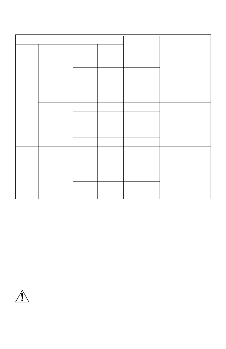
M16638A
ELECTRONIC AIR CLEANER
12
F50
STEP 1:
Remove old power supply and discard.
Fig. 1. Example
3 69-2673EFS—01
Page 4
PS1201A00, PS1202A00 AND PS2401A00 REPLACEMENT POWER SUPPLIES
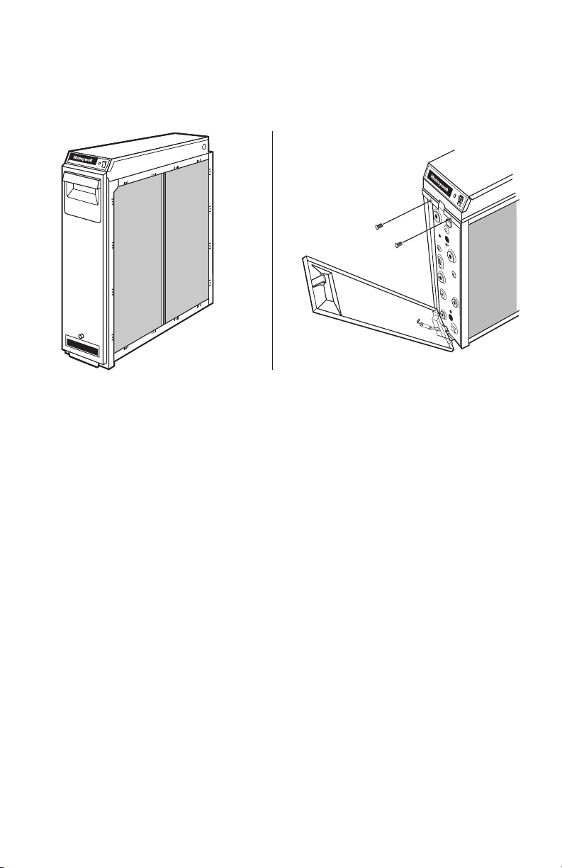
M16635A
34
78
56
OR
OR
Fig. 2. Example
69-2673EFS—01 4
Page 5
PS1201A00, PS1202A00 AND PS2401A00 REPLACEMENT POWER SUPPLIES
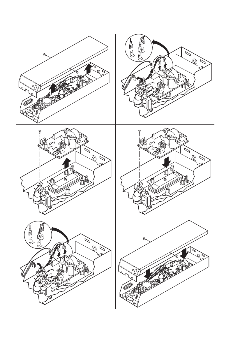
P4
P1
P2
J4
BLACK
W4 W2 W1 W3
AIRFLOW SWITCH BOARD
ORANGE
GRAY
VIOLET
BLACK
1 INTERLOCK SWITCH.
2 SHORTING BAR FOR OZONE REDUCTION.
3 AIRFLOW SWITCH DISABLE JUMPER, R16.
AIRFLOW SWITCH PLUG, J3.
4 NEON LIGHT.
5 OPTIONAL W8600F AIR CLEANER MONITOR.
6 JUMPER LOCATION FOR IONIZER CURRENT SELECTION.
7 JUMPER LOCATION FOR IONIZER VOLTAGE SELECTION.
M32904A
POWER SUPPLY
4
BLACK
BLACK
BLACK
BROWN
BLACK
BLACK
WHITE
GREEN
1
3
J4
J1
BLACK
RED
TEST
BUTTON
CONTACT
BOARD
RED IONIZER
BLACK COLLECTOR
GROUND
CHOKE
GREEN
J8
2
R16
6
7
JUMPER
5
P3
2.1mA
1.65mA
1.29mA
1.05mA
0.9mA
0.25mA
P5
T1
U4
8150V
7500V
P8
STEP 2:
Install new power supply.
a. Position the P5 shorting bar for the size air cleaner you have.
b. Wire the power cord ground lead to the ground choke assembly using a wire
nut. Secure ground connection to the green ground screw on the wiring
compartment barrier.
CHECKOUT
With all components in place, turn on the air cleaner switch and energize the system
blower. Check the following operation:
1. Be sure the neon light is on.
2. Turn off the system blower. The neon light should go off.
3. Turn the system blower back on. The neon light should come back on.
4. With the air cleaner energized, push the test button. A snapping sound indicates
that collector section is energized.
5. With a multispeed blower, repeat steps 2 through 4.
6. If operation is not as described, refer to Troubleshooting and Service section.
5 69-2673EFS—01
Page 6
PS1201A00, PS1202A00 AND PS2401A00 REPLACEMENT POWER SUPPLIES
NO
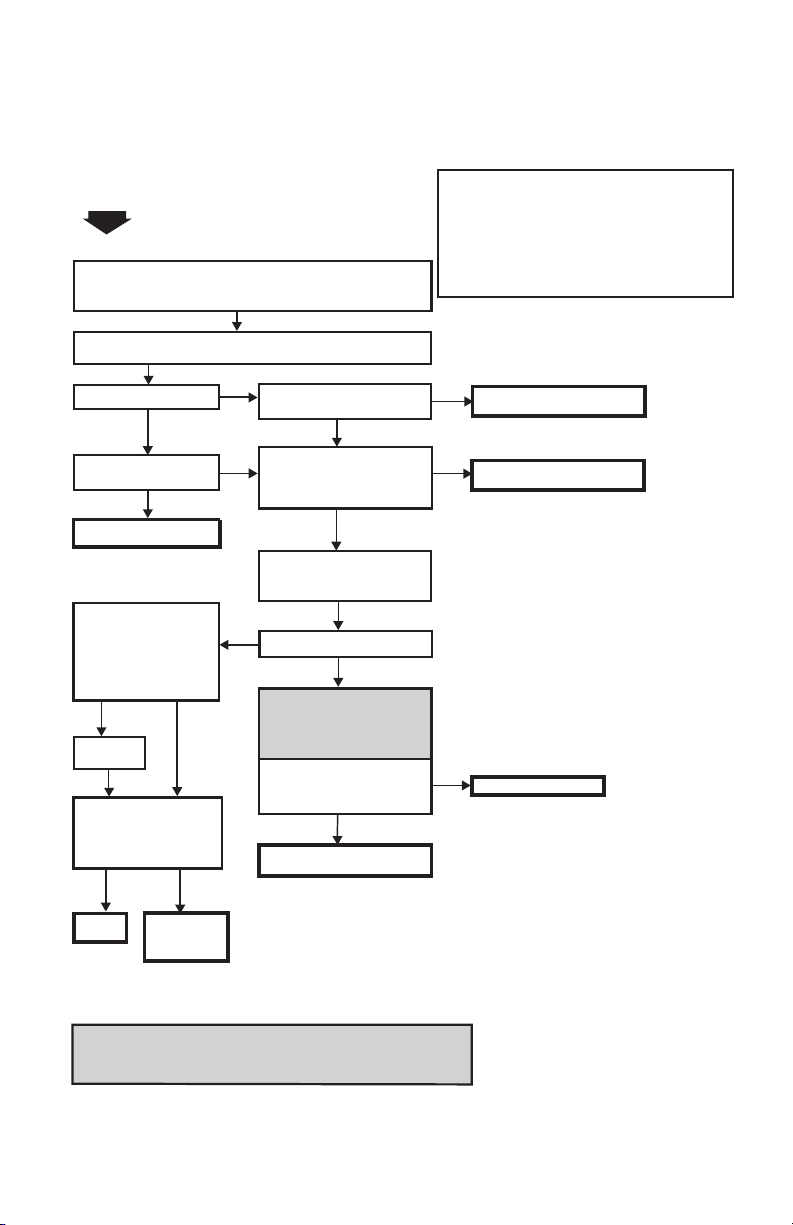
TO USE THIS CHART:
START
OFF
ON
YES
YES
REPLACE LIGHT/SWITCH ASSEMBLY.
MAKE SURE ELECTRONIC CELLS ARE CLEAN, DRY AND PROPERLY INSTALLED.
MAKE SURE METAL PREFILTERS ARE POSITIONED ON THE SIDE WHERE
AIR ENTERS THE AIR CLEANER, AND THAT POST-FILTERS (IF ANY) ARE
POSITIONED ON THE SIDE WHERE AIR LEAVES THE AIR CLEANER.
TURN THE POWER SWITCH ON THE AIR CLEANER ON, AND TURN THE
HVAC FAN ON.
CHECK THE SYSTEM LIGHT
ON THE AIR CLEANER.
PUSH TEST BUTTON ON THE
AIR CLEANER DOOR AND
LISTEN FOR SNAPPING SOUND.
NO
TURN OFF AIR CLEANER POWER
SWITCH. REMOVE THE DOOR AND
CHECK THAT THE CONTACTS ON
THE INSIDE OF THE TEST BUTTON
ARE OK.
YES
AIR CLEANER IS
FUNCTIONING PROPERLY.
CELLS OK.
REPLACE AIR
CLEANER
POWER SUPPLY.
INSPECT THE CELLS FOR
— BENT COLLECTOR PLATES
— BROKEN IONIZER WIRES
— DIRT ACCUMULATION ON
THE INSULATORS
— DAMAGED CONTACTS ON
THE TERMINAL BOARD AT
THE END OF THE CELL
NO
SHORT
CHECK FOR CORRECT INPUT
VOLTAGE ACROSS P1 AND P2
TERMINALS ON POWER
SUPPLY BOARD.
REMOVE THE CELLS (LEAVE THE
PREFILTERS IN PLACE). CLOSE THE
ACCESS DOOR AND TURN ON THE
AIR CLEANER POWER SWITCH.
NO
YES
FIX WIRING.
REPLACE AIR CLEANER
POWER SUPPLY.
M13656
FOLLOW THE STEPS IN ORDER; DO NOT SKIP AROUND.
EACH TIME A PROBLEM IS FIXED, GO BACK TO START.
REPEAT ALL THE STEPS UNTIL THE AIR CLEANER CHECKS
OUT OK.
NOTE: IF A W8600F AIR CLEANER MONITOR IS CONNECTED
TO THE AIR CLEANER, DISCONNECT THE AIR
CLEANER FROM THE W8600F BEFORE STARTING
THIS PROCEDURE. THE W8600F CAN BE CHECKED
SEPARATELY. SEE W8600F INSTRUCTION SHEET.
1.
2.
3.
THIS STEP EXPOSES
DANGEROUSLY HIGH VOLTAGE.
ONLY A QUALIFIED SERVICE
TECHNICIAN SHOULD ATTEMPT
THIS STEP.
WARNING
WITH AN OHMMETER, CHECK
FOR SHORT BETWEEN:
— CELL FRAME AND IONIZER
WIRES
— CELL FRAME AND COLLECTOR
BLADES
SHORT
DETECTED
REPLACE OR
REPAIR CELLS.
YES NO
NO
ELECTRONIC AIR CLEANER TROUBLESHOOTING GUIDE
PUSH TEST BUTTON ON THE
AIR CLEANER DOOR AND
LISTEN FOR SNAPPING SOUND.
REPAIR CONTACTS ON TEST BUTTON.
CHECK THE SYSTEM LIGHT
ON THE AIR CLEANER.
REPLACE
CELLS.
OFF
ON
INCORRECT CONVERSION TO MEDIA AIR CLEANER CAN CAUSE FIRE HAZARD.
WHEN CONVERTING AN ELECTRONIC AIR CLEANER TO A MEDIA AIR CLEANER
THE POWER SUPPLY MUST BE REMOVED OR PERMANENTLY DISABLED.
WARNING
THIS AIR CLEANER PRODUCES A TRACE LEVEL OF OZONE AS A BY-PRODUCT OF NORMAL OPERATION, WHICH IS WELL UNDER THE
LIMIT PRESCRIBED BY THE U.S. F.D.A. PLEASE REFER TO YOUR OWNERS MANUAL FOR FURTHER INFORMATION. FOR A REPLACEMENT
OWNERS MANUAL, CALL 1-800-468-1502 OR VISIT http://yourhome.honeywell.com
TROUBLESHOOTING AND SERVICE
69-2673EFS—01 6
Page 7
PS1201A00, PS1202A00 AND PS2401A00 REPLACEMENT POWER SUPPLIES
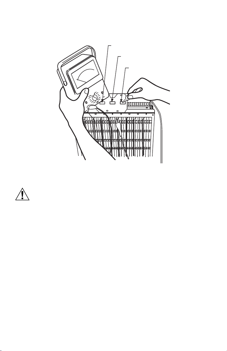
CAUTION
Use an ohmmeter to check the electronic cells for short circuits.
COLLECTOR
TERMINAL
IONIZER
TERMINAL
COLLECTOR
TERMINAL
Modification to Reduce Ozone Odor
Electric Shock Hazard.
Can cause personal injury.
Always disconnect power and open access door before opening power
supply cover.
M6155A
The electronic air cleaner generates a small amount of ozone in normal operation.
During the first week or two of operation, the amount may be higher because of sharp
edges on some of the new high voltage metal parts. Normal use quickly dulls these
edges.
If desired, the ozone generated by the air cleaner can be reduced in one of two ways:
1. Install an activated carbon filter downstream from the air cleaner. Make sure
particles from the air filter cannot fall into the air cleaner.
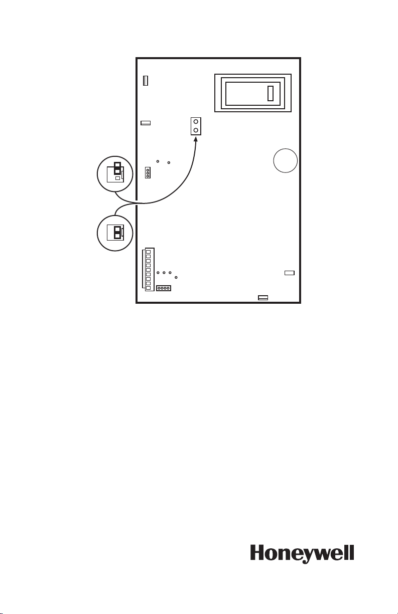
2. Move J8 shorting bar. This will reduce ozone production about 20 to 25 percent
and reduce efficiency about seven to ten percent, depending on actual airflow
delivered by the furnace blower.
a. Unplug or disconnect power supply to the air cleaner.
b. Open the access door.
c. Remove the power box cover.
d. Move J8 shorting bar. See figure below.
7 69-2673EFS—01
Page 8
PS1201A00, PS1202A00 AND PS2401A00 REPLACEMENT POWER SUPPLIES
P3
P4
P1
P2
M32906
J3
J4
J8 SHUNT
IN OZONE
REDUCTION
POSITION
J8 IN
NORMAL
POSITION
J1
J8
Automation and Control Solutions
Honeywell International Inc.
1985 Douglas Drive North
Golden Valley, MN 55422
customer.honeywell.com
® U.S. Registered Trademark
© 2013 Honeywell International Inc.
69-2673EFS—01 M.S. 09-13
Printed in United States
Page 9

Blocs d'alimentation de
rechange PS1201A00,
PS1202A00 et PS2401A00 pour
épurateurs d'air électroniques
NOTICE D’INSTALLATION
APPLICATION
Ce circuit d'alimentation est muni d'une sortie de courant d'ionisateur sélectionnable.
Sélectionner le courant d'ionisateur adéquat en plaçant la tige court-circuit P5 à la
position correcte. Voir le tableau ci-dessous.
Tableau 1.
Courant
Plage de
tension
Bloc
d'alimentation
PS1201A00 102-132
PS1202A00 102-132
PS2401A00 204-264
*Réglage par défaut.
d'entrée
(V c.a.)
V c.a.
V c.a.
V c.a.
Tension
(A)
d'ionisateur
de sortie
(V c.c.)
Fréquence
d'entrée
(Hz)
50 / 60 0,4 7500/8150* 2,1/1,65/1,29/1,05*/
50 / 60 0,4 7500/8150* 2,1/1,65/1,29/1,05*/
50 / 60 0,2 7500/8150* 2,1/1,65/1,29/1,05*/
Courant
d’entrée
d'ionisateur de
sortie (mA)
(sélectionné par la
position de la tige
court-circuit P5)
0,9/0,25
0,9/0,25
0,9/0,25
Page 10

BLOCS D’ALIMENTATION DE RECHANGE PS1201A00, PS1202A00 ET PS2401A00
Tableau 2.
Épurateur d'air
électronique
Modèle Tension
(V c.a.)
F50F 120 20 X 12,5 508 X 318 1,05* PS1201A00
240 20 X 12,5 508 X 318 1,05* PS2401A00
F300A,E 120 20 X 12,5 508 X 318 1,05* PS1201A00
F300B 240 20 X 12,5 508 X 318 1,05* PS2401A00
*Réglage par défaut.
Dimensions
nominales
po mm
16 X 20 406 X 508 1,29
16 x 25 406 X 635 1,65
20 x 20 508 X 508 1,65
20 x 25 508 X 635 2,1
16 X 20 406 X 508 1,29
16 x 25 406 X 635 1,65
20 x 20 508 X 508 1,65
20 x 25 508 X 635 2,1
16 X 20 406 X 508 1,29
16 x 25 406 X 635 1,65
20 x 20 508 X 508 1,65
20 x 25 508 X 635 2,1
d'ionisateur (mA)
Position P5
de courant
Bloc
d'alimentation
de rechange
INSTALLATION
Lors de l’installation de ce produit...
1. Lire attentivement ces instructions. Le non-respect des instructions peut
endommager le produit ou provoquer une situation dangereuse.
2. Vérifier les caractéristiques nominales indiquées dans les instructions et sur le
produit pour s’assurer que le produit correspond bien à l’application prévue.
3. L’installateur doit être un technicien expérimenté ayant reçu la formation
adéquate.
4. Une fois l’installation terminée, vérifier que le produit fonctionne comme indiqué
dans ces instructions.
69-2673EFS—01 2
Page 11

BLOCS D’ALIMENTATION DE RECHANGE PS1201A00, PS1202A00 ET PS2401A00
MISE EN GARDE
M16638A
ELECTRONIC AIR CLEANER
12
F50
Risque de choc électrique. Peut provoquer des chocs électriques ou
endommager le matériel.
Débrancher l'alimentation avant d'installer le bloc d'alimentation de
rechange.
ÉTAPE 1 :
Retirer l'ancien bloc d'alimentation et le mettre au rebut.
Fig. 1. Exemple
3 69-2673EFS—01
Page 12

BLOCS D’ALIMENTATION DE RECHANGE PS1201A00, PS1202A00 ET PS2401A00
MF16635A
34
78
56
OU
OU
Fig. 2. Exemple
69-2673EFS—01 4
Page 13

BLOCS D’ALIMENTATION DE RECHANGE PS1201A00, PS1202A00 ET PS2401A00
ÉTAPE 2 :
Installer le bloc d'alimentation neuf.
COLLECTEUR NOIR
IONISATEUR ROUGE
NOIR
4
NOIR
P3
P4
P8
7
J4
U4
J8
2
7500V
8150V
6
BLOC D'ALIMENTATION
T1
P5
0,25mA
0,9mA
1,05mA
1,29mA
1,65mA
2,1mA
ROUGE
NOIR
BOUTON
DE TEST
PLAQUE
À CONTACTS
NOIR
MARRON
P2
1
NOIR
NOIR
NOIR
BLANC
VERT
VERT
3
5
CAVALIER
1 INTERRUPTEUR DE VERROUILLAGE.
2 TIGE COURT-CIRCUIT POUR
RÉDUCTION D’OZONE.
3 CAVALIER DE DÉSACTIVATION DE
COMMUTATEUR DE DÉBIT D’AIR, R16.
PRISE DE COMMUTATEUR DE DÉBIT D’AIR, J3.
4 NÉON.
5 MONITEUR D’ÉPURATEUR D’AIR W8600F EN OPTION.
6 EMPLACEMENT DU CAVALIER POUR SÉLECTION DU COURANT DE L'IONISATEUR.
7 EMPLACEMENT DU CAVALIER POUR SÉLECTION DE LA TENSION DE L'IONISATEUR.
J4
J1
R16
ORANGE
GRIS
VIOLET
NOIR
P1
W4 W2 W1 W3
TABLEAU DE COMMUTATEUR DE DÉBIT D’AIR
a. Positionner la tige court-circuit P5 en fonction de la dimension de l'épurateur
d'air installé.
b. Câbler le fil de terre du cordon d’alimentation à l’inducteur de terre à l’aide
d'un serre-fil. Fixer la connexion de terre à la vis de terre verte sur la barrière
du compartiment de câblage.
VÉRIFICATION
Avec tous les composants en place, actionner l’interrupteur de l’épurateur d’air et
actionner la soufflante du système. Vérifier les éléments suivants :
1. S'assurer que le néon est allumé.
2. Désactiver la soufflante du système. Le néon doit s'éteindre.
3. Remettre la soufflante en marche. Le néon doit se rallumer.
4. Une fois l’épurateur d’air activé, appuyer sur le bouton de test. Un claquement
indique que la section du collecteur est activée.
5. Avec une soufflante à plusieurs vitesses, répéter les étapes 2 à 4.
6. Si le fonctionnement n’a pas lieu tel que décrit, consulter la section Dépannage
et entretien.
INDUCTEUR
DE TERRE
MF32904A
5 69-2673EFS—01
Page 14

BLOCS D’ALIMENTATION DE RECHANGE PS1201A00, PS1202A00 ET PS2401A00
NON
POUR UTILISER CE TABLEAU :
DÉMARRAGE
ARRÊT
OUI
REMPLACER L’ENSEMBLE TÉMOIN/
INTERRUPTEUR.
S'ASSURER QUE LES CELLULES ÉLECTRONIQUES SONT PROPRES, SÈCHES ET
CORRECTEMENT INSTALLÉES. S'ASSURER QUE LES PRÉFILTRES MÉTALLIQUES SONT
POSITIONNÉS SUR LE CÔTÉ OÙ L’AIR PÉNÈTRE DANS L’ÉPURATEUR D’AIR, ET QUE LES
POST-FILTRES (LE CAS ÉCHÉANT) SONT POSITIONNÉS SUR LE CÔTÉ OÙ L'AIR SORT DE
L'ÉPURATEUR.
METTRE L’INTERRUPTEUR D’ALIMENTATION DE L'ÉPURATEUR D'AIR SUR MARCHE ET
METTRE LE VENTILATEUR DE CVCA EN MARCHE.
CONTRÔLER LE TÉMOIN DU SYSTÈME SUR
L'ÉPURATEUR D’AIR.
APPUYER SUR LE BOUTON DE TEST SUR LA
PORTE DE L'ÉPURATEUR D'AIR. UN
CLAQUEMENT DOIT SE FAIRE ENTENDRE.
NON
APPUYER SUR L'INTERRUPTEUR
D'ALIMENTATION POUR ÉTEINDRE
L’ÉPURATEUR D’AIR. RETIRER LA
PORTE ET VÉRIFIER QUE LES
CONTACTS À L'INTÉRIEUR DU
BOUTON DE TEST SONT EN BON ÉTAT.
OUI
L’ÉPURATEUR D’AIR FONCTIONNE
CORRECTEMENT.
CELLULES EN BON ÉTAT.
REMPLACER LE BLOC
D'ALIMENTATION DE
L'ÉPURATEUR D'AIR.
INSPECTER LES CELLULES POUR DÉTECTER
LES PROBLÈMES SUIVANTS :
— PLAQUES DE COLLECTEUR COURBÉES
— FILS D’IONISATEUR CASSÉS
— ACCUMULATION DE SALETÉ SUR LES
ISOLATEURS
— CONTACTS ENDOMMAGÉS SUR LA
PLAQUE À BORNES À L'EXTRÉMITÉ DE LA
CELLULE
PAS DE
COURT-CIRCUIT
VÉRIFIER QUE LA TENSION
D’ENTRÉE EST CORRECTE ENTRE
LES BORNES P1 ET P2 DU TABLEAU
D’ALIMENTATION.
RETIRER LES CELLULES (LAISSER
LES PRÉFILTRES EN PLACE).
FERMER LA PORTE D’ACCÈS ET
ALLUMER L’ÉPURATEUR D’AIR.
NON
OUI
RÉPARER LES CÂBLES.
REMPLACER LE BLOC
D'ALIMENTATION DE L'ÉPURATEUR
D'AIR.
MF13656
SUIVRE LES ÉTAPES DANS L’ORDRE. N'EN
SAUTER AUCUNE.
DÈS QU’UN PROBLÈME EST RÉSOLU,
RECOMMENCER AU DÉBUT.
RÉPÉTER TOUTES LES ÉTAPES JUSQU’À CE
QUE L’ÉPURATEUR FONCTIONNE
CORRECTEMENT.
REMARQUE : SI UN MONITEUR D’ÉPURATEUR
D’AIR W8600F EST CONNECTÉ À L’ÉPURATEUR,
DÉBRANCHER L’ÉPURATEUR DU MONITEUR
W8600F AVANT DE COMMENCER CETTE
PROCÉDURE. LE MONITEUR W8600F PEUT ÊTRE
CONTRÔLÉ SÉPARÉMENT. CONSULTER LA
FEUILLE D’INSTRUCTION W8600F.
1.
2.
3.
CETTE ÉTAPE EXPOSE À UNE
HAUTE TENSION DANGEREUSE.
SEUL UN TECHNICIEN D’ENTRETIEN
QUALIFIÉ EST HABILITÉ À
ENTREPRENDRE CETTE ÉTAPE.
AVERTISSEMENT
AVEC UN OHMMÈTRE, VÉRIFIER L’ABSENCE DE
COURTS-CIRCUITS ENTRE :
— CADRE DES CELLULES ET FILS DE L’IONISATEUR
— CADRE DES CELLULES ET LAMES DU
COLLECTEUR
COURT-CIRCUIT
DÉTECTÉ
REMPLACER OU
RÉPARER LES CELLULES.
MARCHE
OUI
OUI NON
NON
GUIDE DE DÉPANNAGE DE L’ÉPURATEUR D’AIR ÉLECTRONIQUE
APPUYER SUR LE BOUTON DE TEST
SUR LA PORTE DE L'ÉPURATEUR
D'AIR. UN CLAQUEMENT DOIT SE
FAIRE ENTENDRE.
RÉPARER LES CONTACTS SUR LE
BOUTON DE TEST.
CONTRÔLER LE TÉMOIN DU
SYSTÈME SUR L'ÉPURATEUR D’AIR.
REMPLACER
LES CELLULES.
ARRÊT
MARCHE
UNE CONVERSION INCORRECTE À UN ÉPURATEUR D’AIR À FIBRES PEUT CAUSER DES RISQUES D'INCENDIE.
LORS DE LA CONVERSION D’UN ÉPURATEUR D'AIR ÉLECTRONIQUE À UN ÉPURATEUR D'AIR À FIBRES, LE
BLOC D'ALIMENTATION DOIT ÊTRE RETIRÉ OU DÉSACTIVÉ DE FAÇON PERMANENTE.
AVERTISSEMENT
CET ÉPURATEUR D’AIR PRODUIT DES TRACES D’OZONE EN TANT QUE PRODUIT RÉSULTANT DU FONCTIONNEMENT NORMAL, QUI SONT SITUÉES
BIEN EN DEÇÀ DU SEUIL PRESCRIT PAR LA FDA AMÉRICAINE. MERCI DE CONSULTER LE MANUEL DU PROPRIÉTAIRE POUR PLUS D'INFORMATIONS.
POUR OBTENIR UN MANUEL DU PROPRIÉTAIRE DE RECHANGE, MERCI D'APPELER LE 1-800-468-1502 OU DE VISITER http://yourhome.honeywell.com.
DÉPANNAGE ET ENTRETIEN
69-2673EFS—01 6
Page 15

BLOCS D’ALIMENTATION DE RECHANGE PS1201A00, PS1202A00 ET PS2401A00
MISE EN GARDE
Utiliser un ohmmètre pour vérifier l'absence de court-circuit au niveau des cellules
électroniques.
BORNE DU
COLLECTEUR
BORNE DE
L'IONISATEUR
BORNE DU
COLLECTEUR
MF6155A
Modification pour réduire l’odeur d’ozone
Risque de choc électrique.
Peut causer des blessures.
Toujours débrancher l’alimentation et ouvrir la porte d’accès avant
d’ouvrir le couvercle du bloc d’alimentation.
En fonctionnement normal, l’épurateur d’air électronique génère une petite quantité
d’ozone. Durant la première semaine ou les deux premières semaines de
fonctionnement, la quantité d'ozone dégagée peut être supérieure en raison des bords
coupants présents sur certaines pièces métalliques haute tension neuves. Une
utilisation normale émousse rapidement ces bords.
Si cela est souhaité, l’ozone généré par l’épurateur d’air peut être réduit de l'une des
deux manières suivantes :
1. Installer un filtre à charbon actif en aval de l'épurateur d'air. S’assurer que les
particules du filtre à air ne retombent pas sur l'épurateur d'air.
7 69-2673EFS—01
Page 16

BLOCS D'ALIMENTATION DE RECHANGE PS1201A00, PS1202A00 ET
2. Déplacer la tige court-circuit J8. Ceci permet de réduire la production d’ozone de
20-25 % et de réduire l’efficacité d’environ 7 à 10 % en fonction du flux d’air réel
délivré par la soufflante de la chaudière.
a. Débrancher ou déconnecter le bloc d’alimentation de l’épurateur d’air.
b. Ouvrir la porte d’accès.
c. Retirer le couvercle du boîtier d’alimentation.
d. Déplacer la tige court-circuit J8. Voir la figure ci-dessous.
P3
J8 SHUNT EN
POSITION DE
RÉDUCTION
D’OZONE
J8 EN
POSITION
NORMALE
P4
J4
J1
J8
J3
P2
P1
MF32906
Solutions de régulation et d’automatisation
Honeywell International Inc.
1985 Douglas Drive North
Golden Valley, MN 55422
customer.honeywell.com
® Marque de commerce déposée aux États-Unis
© 2013 Honeywell International Inc.
Tous droits réservés
69-2673EFS—01 M.S. 09-13
Imprimé aux États-Unis
Page 17

Fuente de energía de repuesto
PS1201A00, PS1202A00 y
PS2401A00 para limpiadores
electrónicos de aire
INSTRUCCIONES PARA LA INSTALACIÓN
APLICACIÓN
El tablero de esta fuente de energía tiene una salida de corriente del ionizador
seleccionable. La selección correcta de la corriente del ionizador se logra moviendo la
barra de cortocircuito P5 a la posición adecuada. Consulte la tabla a continuación.
Tabla 1.
Corriente de salida
Rango de
voltaje de
Fuente de
energía
PS1201A00 102-132
PS1202A00 102-132
PS2401A00 204-264
*Configuración predeterminada.
entrada
(V CA)
V CA
V CA
V CA
Frecuencia
de entrada
(Hz)
50/60 0.4 7500/
50/60 0.4 7500/
50/60 0.2 7500/
Corriente
de entrada
(A)
Voltaje de
salida del
ionizador
(V CD)
8150*
8150*
8150*
del ionizador (mA)
(Seleccionado por la
posición de la barra
de cortocircuito P5)
2.1/1.65/1.29/1.05*/
0.9/0.25
2.1/1.65/1.29/1.05*/
0.9/0.25
2.1/1.65/1.29/1.05*/
0.9/0.25
Page 18

FUENTE DE ENERGÍA DE REPUESTO PS1201A00, PS1202A00 Y PS2401A00
Tabla 2.
Limpiador electrónico
de aire
Modelo Voltaje (V CA) in mm
F50F 120 20 X 12.5 508 X 318 1.05* PS1201A00
240 20 X 12.5 508 X 318 1.05* PS2401A00
F300A, E 120 20 X 12.5 508 X 318 1.05* PS1201A00
F300B 240 20 X 12.5 508 X 318 1.05* PS2401A00
*Configuración predeterminada.
Tamaño nominal Posición P5 de
la corriente del
ionizador (mA)
16 X 20 406 X 508 1.29
16 x 25 406 X 635 1.65
20 x 20 508 X 508 1.65
20 x 25 508 X 635 2.1
16 X 20 406 X 508 1.29
16 x 25 406 X 635 1.65
20 x 20 508 X 508 1.65
20 x 25 508 X 635 2.1
16 X 20 406 X 508 1.29
16 x 25 406 X 635 1.65
20 x 20 508 X 508 1.65
20 x 25 508 X 635 2.1
Fuente de
energía de
repuesto
INSTALACIÓN
Al instalar este producto, lleve a cabo los siguientes pasos:
1. Lea detenidamente estas instrucciones. De no seguirlas, se podría dañar el
producto o provocar una situación peligrosa.
2. Verifique los valores nominales indicados en el producto y en las instrucciones,
para asegurarse de que el producto sea adecuado para la aplicación.
3. El instalador debe ser un técnico de servicio capacitado y experimentado.
4. Después de terminar la instalación, verifique el funcionamiento del producto tal
como se indica en estas instrucciones.
69-2673EFS—01 2
Page 19

FUENTE DE ENERGÍA DE REPUESTO PS1201A00, PS1202A00 Y PS2401A00
PRECAUCIÓN
M16638A
ELECTRONIC AIR CLEANER
12
F50
Peligro de descarga eléctrica. Puede causar descargas eléctricas o
daños al equipo.
Desconecte la energía antes de instalar la fuente de energía de repuesto.
PASO 1 .
Quite la fuente de energía anterior y deséchela.
Fig. 1. Ejemplo
3 69-2673EFS—01
Page 20

FUENTE DE ENERGÍA DE REPUESTO PS1201A00, PS1202A00 Y PS2401A00
MS16635A
34
78
56
O
O
Fig. 2. Ejemplo
69-2673EFS—01 4
Page 21

FUENTE DE ENERGÍA DE REPUESTO PS1201A00, PS1202A00 Y PS2401A00
P4
P1
P2
J4
NEGRO
W4 W2 W1 W3
TABLERO DEL INTERRUPTOR DE FLUJO DE AIRE
ANARANJADO
GRIS
VIOLETA
NEGRO
MS32904A
FUENTE DE ENERGÍA
4
NEGRO
NEGRO
NEGRO
MARRÓN
NEGRO
NEGRO
BLANCO
VERDE
1
3
J4
J1
NEGRO
ROJO
BOTÓN DE
PRUEBA
TABLERO DE
CONTACTO
IONIZADOR COLOR ROJO
COLECTOR COLOR NEGRO
1 INTERRUPTOR DE SEGURO.
2 BARRA DE CORTOCIRCUITO
PARA REDUCCIÓN DE OZONO.
3 C3 PUENTE DE CIERRE DEL INTERRUPTOR
DE FLUJO DE AIRE, R16.
ENCHUFE DEL INTERRUPTOR DE FLUJO DE AIRE, J3.
4 LUZ DE NEÓN.
5 MONITOR W8600F OPCIONAL DEL LIMPIADOR DE AIRE.
6 LUGAR DEL PUENTE PARA LA SELECCIÓN DE LA CORRIENTE DEL IONIZADOR.
7 LUGAR DEL PUENTE PARA LA SELECCIÓN DEL VOLTAJE DEL IONIZADOR.
ESTRANGULADOR
A TIERRA
VERDE
J8
2
R16
6
7
PUENTE
5
P3
2.1mA
1.65mA
1.29mA
1.05mA
0.9mA
0.25mA
P5
T1
U4
8150V
7500V
P8
PASO 2 .
Instale la fuente de energía nueva.
a. Configure la barra de cortocircuito P5, según el tamaño del limpiador de aire
b. Conecte el cable a tierra del cordón conductor al ensamble de estrangulador
que tenga.
a tierra con un conector de empalme para cables. Asegure la conexión a
tierra al tornillo verde de puesta a tierra en el tabique del compartimiento de
cableado.
VERIFICACIÓN
Una vez que todos los componentes estén en su lugar, encienda el interruptor del
limpiador de aire y suministre energía al soplador del sistema. Verifique el
funcionamiento que se describe a continuación:
1. Cerciórese de que la luz de neón esté encendida.
2. Apague el soplador del sistema. La luz de neón se debe apagar.
3. Encienda el soplador del sistema nuevamente. La luz de neón se debe volver a
encender.
4. Después de haberle suministrado energía al limpiador de aire, presione el botón
de prueba. El sonido de chasquido indica que se ha suministrado energía a la
sección del recolector.
5. Con un soplador de velocidades múltiples, repita los pasos 2 a 4.
6. Si el funcionamiento no es el que se describe, consulte la sección Solución de
problemas y tareas de servicio.
5 69-2673EFS—01
Page 22

FUENTE DE ENERGÍA DE REPUESTO PS1201A00, PS1202A00 Y PS2401A00
NO
PARA USAR ESTE CUADRO, HAGA LO SIGUIENTE:
INICIO
APAGADO
SÍ
REEMPLACE EL ENSAMBLE DE
LUZ/INTERRUPTOR
CERCIÓRESE DE QUE LAS CELDAS ELECTRÓNICAS ESTÉN LIMPIAS, SECAS E INSTALADAS
CORRECTAMENTE. CERCIÓRESE DE QUE LOS PREFILTROS DE METAL ESTÉN POSICIONADOS
EN EL COSTADO, DONDE INGRESA EL AIRE AL LIMPIADOR DE AIRE; ADEMÁS, ASEGÚRESE DE
QUE LOS POSFILTROS (SI HAY ALGUNO) ESTÉN POSICIONADOS EN EL COSTADO, DESDE
DONDE SALE EL AIRE DEL LIMPIADOR DE AIRE.
ENCIENDA EL INTERRUPTOR DE ENERGÍA DEL LIMPIADOR DE AIRE Y EL VENTILADOR DEL
SISTEMA DE CALEFACCIÓN, VENTILACIÓN Y AIRE ACONDICIONADO (HEATING, VENTILATION
AND AIR CONDITIONING, HVAC).
VERIFIQUE LA LUZ DEL SISTEMA DEL
LIMPIADOR DE AIRE.
PRESIONE EL BOTÓN DE PRUEBA DE LA
PUERTA DEL LIMPIADOR DE AIRE Y PRESTE
ATENCIÓN PARA VERIFICAR QUE SE
ESCUCHE EL SONIDO DE CHASQUIDO.
NO
APAGUE EL INTERRUPTOR DE
ENERGÍA DEL LIMPIADOR DE AIRE.
QUITE LA PUERTA Y VERIFIQUE QUE
LOS CONTACTOS INTERNOS DEL
BOTÓN DE PRUEBA ESTÉN EN
BUENAS CONDICIONES.
SÍ
LAS CELDAS ESTÁN EN
BUENAS CONDICIONES.
REEMPLACE LA FUENTE
DE ENERGÍA DEL
LIMPIADOR DE AIRE.
INSPECCIONE LAS CELDAS EN BUSCA DE
LOS SIGUIENTES PROBLEMAS:
— PLACAS DEL COLECTOR DOBLADAS
— CABLES DEL IONIZADOR ROTOS
— ACUMULACIÓN DE SUCIEDAD EN LOS
AISLADORES
— CONTACTOS DAÑADOS EN EL TABLERO
DE TERMINALES DEL FINAL DE LA CELDA
NO SE DETECTÓ
NINGÚN
CORTOCIRCUITO
VERIFIQUE QUE EL VOLTAJE DE
ENTRADA ENTRE LOS TERMINALES
P1 Y P2 DEL TABLERO DE LA FUENTE
DE ENERGÍA SEA EL CORRECTO.
QUITE LA CELDAS (DEJE LOS
PREFILTROS EN SU LUGAR). CIERRE
LA PUERTA DE ACCESO Y ENCIENDA
EL INTERRUPTOR DE ENERGÍA DEL
LIMPIADOR DE AIRE.
NO
SÍ
REPARE EL CABLEADO.
REEMPLACE LA FUENTE DE
ENERGÍA DEL LIMPIADOR DE AIRE.
MS13656
SIGA LOS PASOS EN ORDEN Y NO SALTEE
NINGUNO.
DESPUÉS DE SOLUCIONAR UN PROBLEMA,
VUELVA AL COMIENZO.
REPITA TODOS LOS PASOS HASTA OBTENER UN
BUEN RESULTADO CON LA VERIFICACIÓN DEL
LIMPIADOR DE AIRE.
NOTA: SI UN MONITOR W8600F DE LIMPIADOR
DE AIRE ESTÁ CONECTADO AL LIMPIADOR DE
AIRE, DESCONÉCTELO DEL MONITOR W8600F
ANTES DE COMENZAR CON ESTE
PROCEDIMIENTO. EL MONITOR W8600F SE
PUEDE VERIFICAR POR SEPARADO. CONSULTE
LA HOJA DE INSTRUCCIONES DEL MONITOR
W8600F.
1.
2.
3.
AL LLEVAR A CABO ESTE PASO, LAS
PERSONAS QUEDAN EXPUESTAS A
VOLTAJE PELIGROSAMENTE ALTO.
SOLO UN TÉCNICO DE SERVICIO
CALIFICADO DEBE INTENTAR
LLEVARLO A CABO.
ADVERTENCIA
CON UN OHMÍMETRO, VERIFIQUE SI SE PRODUJO
UN CORTOCIRCUITO ENTRE LOS SIGUIENTES
COMPONENTES:
— LA ESTRUCTURA DE LA CELDA Y LOS CABLES
DEL IONIZADOR
— LA ESTRUCTURA DE LA CELDA Y LAS HOJAS DEL
COLECTOR
SE DETECTÓ UN
CORTOCIRCUITO
REEMPLACE O REPARE
LAS CELDAS.
ENCENDIDO
EL LIMPIADOR DE AIRE FUNCIONA
CORRECTAMENTE.
SÍ
SÍ NO
NO
GUÍA DE SOLUCIÓN DE PROBLEMAS DEL LIMPIADOR
DE AIRE ELECTRÓNICO
PRESIONE EL BOTÓN DE PRUEBA DE
LA PUERTA DEL LIMPIADOR DE AIRE Y
PRESTE ATENCIÓN PARA VERIFICAR
QUE SE ESCUCHE EL SONIDO DE
CHASQUIDO.
REPARE LOS CONTACTOS DEL
BOTÓN DE PRUEBA.
VERIFIQUE LA LUZ DEL SISTEMA DEL
LIMPIADOR DE AIRE.
REEMPLACE
LAS CELDAS
APAGADO
ENCENDIDO
LA CONVERSIÓN INCORRECTA A UN LIMPIADOR DE AIRE NO ELECTRÓNICO PUEDE CAUSAR PELIGRO DE
INCENDIOS. AL CONVERTIR UN LIMPIADOR DE AIRE ELECTRÓNICO A UNO NO ELECTRÓNICO, SE DEBE
QUITAR LA FUENTE DE ENERGÍA, O BIEN DESACTIVARLA DE MANERA PERMANENTE.
ADVERTENCIA
ESTE LIMPIADOR DE AIRE PRODUCE CIERTO NIVEL DE HUELLA DE OZONO COMO PRODUCTO DERIVADO DEL FUNCIONAMIENTO NORMAL, QUE
SE ENCUENTRA MUY POR DEBAJO DEL LÍMITE ESTABLECIDO POR LA ADMINISTRACIÓN DE ALIMENTOS Y MEDICAMENTOS (FOOD AND DRUG
ADMINISTRATION, FDA) DE LOS ESTADOS UNIDOS. CONSULTE EL MANUAL DEL USUARIO PARA OBTENER MÁS INFORMACIÓN. PARA OBTENER UN
MANUAL DEL USUARIO DE REPUESTO, LLAME AL 1-800-468-1502 O VISITE http://yourhome.honeywell.com
SOLUCIÓN DE PROBLEMAS Y TAREAS DE SERVICIO
69-2673EFS—01 6
Page 23

FUENTE DE ENERGÍA DE REPUESTO PS1201A00, PS1202A00 Y PS2401A00
PRECAUCIÓN
Use un ohmímetro para verificar si se produjeron cortocircuitos en las celdas
electrónicas.
TERMINAL DEL
COLECTOR
TERMINAL DEL
IONIZADOR
TERMINAL DEL
COLECTOR
MS6155A
Modificación para reducir el olor a ozono
Peligro de descarga eléctrica.
Puede ocasionar lesiones personales.
Siempre desconecte la energía y abra la puerta de acceso antes de abrir
la cubierta de la fuente de energía.
El limpiador de aire electrónico genera una pequeña cantidad de ozono durante el
funcionamiento normal. Durante las primeras una o dos semanas de funcionamiento,
la cantidad puede ser mayor, debido a los bordes afilados de algunas de las partes de
metal nuevas con alto voltaje. El uso normal desgasta estos bordes rápidamente.
Si así lo desea, se puede reducir el ozono generado por el limpiador de aire mediante
una de estas dos maneras:
1. Instale un filtro de carbono activado de forma descendente en el limpiador de
aire. Cerciórese de que las partículas capturadas por el filtro de aire no se
depositen en el limpiador de aire.
7 69-2673EFS—01
Page 24

FUENTE DE ENERGÍA DE REPUESTO PS1201A00, PS1202A00 Y PS2401A00
P3
P4
P1
P2
MS32906
J3
J4
DERIVACIÓN J8
EN POSICIÓN DE
REDUCCIÓN DE
OZONO
J8 EN
POSICIÓN
NORMAL
J1
J8
2. Mueva la barra de cortocircuito J8. Esto reducirá la producción de ozono entre
20 y 25 %, además de disminuir la eficacia entre siete y diez por ciento, según el
flujo de aire real que pasa por el soplador del calefactor.
a. Desenchufe o desconecte la fuente de energía del limpiador de aire.
b. Abra la puerta de acceso.
c. Quite la cubierta de la caja eléctrica.
d. Mueva la barra de cortocircuito J8. Consulte la figura a continuación.
Automatización y control desenlace
Honeywell International Inc.
1985 Douglas Drive North
Golden Valley, MN 55422
customer.honeywell.com
® Marca Registrada en los Estados Unidos
© 2013 Hoeywell International Inc.
Todos los derechos reservados
69-2673EFS—01 M.S. 09-13
Impreso en Estados Unidos
 Loading...