

Page 1
NA228S-C
Einbau-Anleitung • Installation and operating instructions
11
14
X
IN
A
M
M
C
3
B
2
Sens.k
B
1
B
R
U
EB-NA228S-C=C
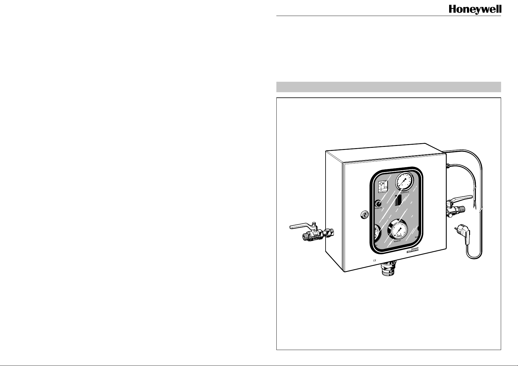
Nachfüllautomat
für offene Heizungsanlagen
Automatic refilling unit
for open heating systems
Page 2
Allgemeine Hinweise
Allgemeine Hinweise
1. Ausführung
2. Aufgaben
Lage der oberen
und unteren
11
14
X
N
I
A
M
M
C
3
B
2
Sens.k
B
1
B
R
U
Tauchelektrode
200 mm
11
14
Sens.k
C
MAX
MIN
B1
B2B3
R
U
Ein- und ausgangsseitige Absperrung
●
● Gehäuse aus Stahlblech, pulverbeschichtet
● Trinkwasser- und Anlagenanschluss mit Absperrkugelhahn DIN 2999 R
1
/2'’ oder
Lötanschluss ∅ 15 mm
● Summierzähler addiert die Anzahl der Nachfüllvorgänge mit Rückstellschlüssel
● Zeitrelais stufenlos einstellbar zwischen 6-60 min. zur Begrenzung der Fülldauer
● Meldeleuchte für Störfälle und Entriegelungstaste
● Manometer für Zulauf und Anlagendruck
● Ablauftrichter für Anschluss von Kunststoffrohr DN 40
● 2 Elektroden für oberen und unteren Wasserstand mit je 4 m Kabel
● EIN-/AUS-Schalter, 2-polig, beleuchtet
● Elektrischer Anschluss 230 V~ / 50/60 Hz, steckerfertig
● 1 m Anschlusskabel für Elektrodenanschluss am Gerät
● Durchführungstülle für Leitwartenanschlusskabel
● Niveauwächter
● Wasserzähler
●
Konstanthaltung des Systemdruckes in off enen Heizkreisläuf en zwischen
vorgegebenen oberen und unteren Grenzwerten
● Verhinderung von Rückfließen, Rücksaugen oder Rückdrücken des Heiz- oder
Kühlwasser in das Trinkwassernetz
● Möglichkeit des Schnell- und automatischen Nachfüllens der Anlage
● Vermeidung von Dampfbildung durch Druckabfall im System.
32
Page 3

Allgemeine Hinweise
Allgemeine Hinweise
3. Verwendungsbereich
Der vollautomatische Nachfüllautomat NA228 S-C mit seinen D VGW -bauteilgeprüften Armaturen
● Rohrtrenner Typ: R295SA-½, DIN/DV GW 569 VE
● Rückflussverhinderer Typ: RV282-½, DVGW-Nr. 0572
erlaubt eine ständige feste Verbindung von offenen Heizkreisläufen mit der Trinkwasseranlage. Insbesondere gilt dies für Heizungsanlagen nach DIN 4751 Blatt 1
Für die nachgeschalteten Anlagen gelten folgende Betriebsdaten:
Anlagendruck max. = 4 bar
Temperatur max. = 100°C.
4. Prüfung
Die technischen Prüfungen des vollautomatischen Nachfüllautomaten NA228S-C erfolgten
durch den TÜV Bay e rn, Hessen, Sachsen, Südwest E.V. unter der Prüf-Nr . AW-SEZ/408/97
5. Technische Daten
Nachfüllen Volumenstrom 110 l/h bei ∆p = 2 bar
Schnellfüllen Volumenstrom stufenlos einstellbar zwischen 110 l/h und 1100 l/h
bei ∆p = 2 bar
Fülldauer Einstellbar 6 - 60 min.
(werkseitig eingestellt auf 12 min.)
Wasserstand Signalgebung durch Tauchelektroden für oberen und unteren
Grenzwert
Tauchelektrodenabstand ca. 200 mm
Netzdruck min. 1,5 bar; max. 4 bar
Spannungsversorgung 230 V
Spannungsversorgung
der T auchelektroden: 24 V
Leistungsaufnahme 30 W
Abmessungen Höhe 380 mm
Gewicht ca. 16 kg
~
50/60 Hz
~
50/60 Hz; ab Niveauwächter
Sicherheitsschutztransformator kurzschlussfest
Breite 370 mm
Tiefe 160 mm
Den Prüfungen liegen folgende DIN-Normen und Arbeitsblätter zugrunde:
● DIN 3266 Teil 1 / Teil 2
● Prüfungen zur elektrischen und mechanischen Sicherheit 1/EN61010 - 1.3.1994 CE
Niederspannungsrichtlinien
54
Page 4
Allgemeine Hinweise
Allgemeine Hinweise
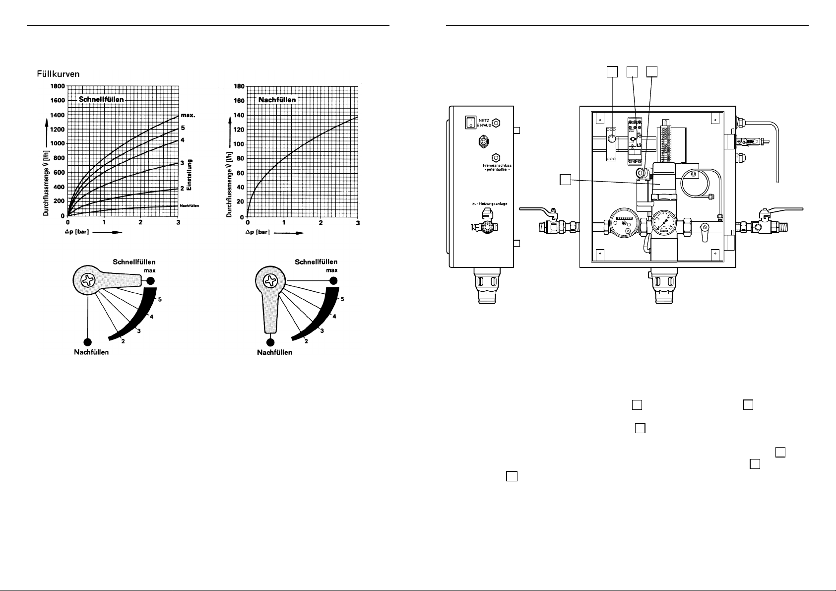
6. Durchflussdiagramme
7. Funktionsbeschreibung
5
10
13
A1 11
C MAX MIN
Sens.k
R
U
3
15
ENS
mecotron
A2
A1
12
11
14
C
MAX
MIN
B1
B2B3
A2141812
16
Die Durchflussmenge bzw. die Fülldauer
beim Schnellfüllen ist abhängig von der
Stellung des Kugelhahnes.
Nach Beendigung des Füllvorgangs ist der
Hebel des Kugelhahnes auf die Stellung
„Nachfüllen“ einzustellen.
Eine Sperre in der Gerätetür verhindert,
dass das Gerät geschlossen werden kann,
wenn der Hebel sich nicht in der Position
„Nachfüllen“ befindet.
Aus dem W asserzählerstand alt/neu kann
die Nachfüllmenge abgelesen werden.
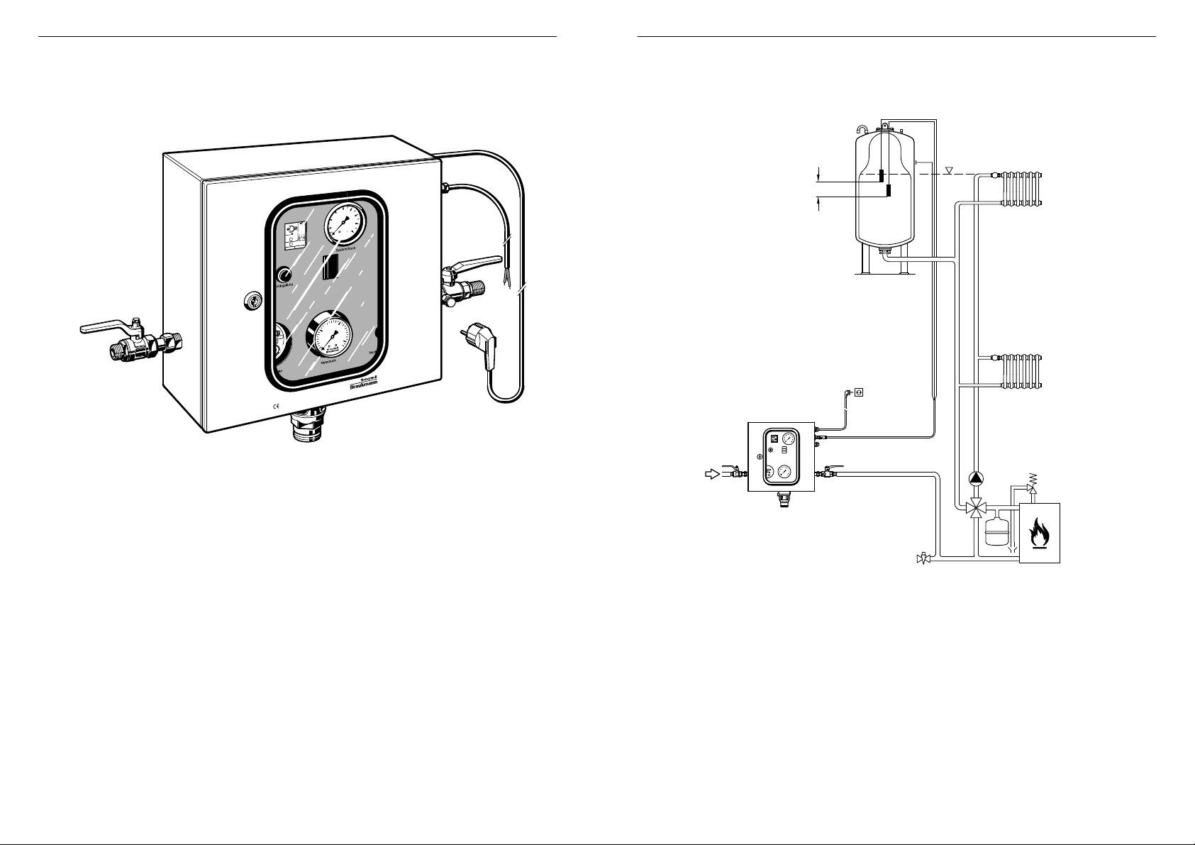
Sinkt der Anlagendruck, z.B. durch Leckv erluste, unter den eingestellten unteren Grenzwert
des Anlagendrucks, so wird das Umschaltventil 3 über den Niveauwächter 13 durch
elektrischen Impuls der T auchelektroden geöffnet und eine h ydraulische V erbindung vom
Wassernetz zum Steuerkolben des Rohtrenners 5 hergestellt. Der Netzdruck steuert den
Rohrtrenner in Durchflussstellung und die Anlage wird nachgefüllt bis zur Höhe des gewünschten Anlagendrucks. Die Zeitdauer des Nachfüllvorganges wird vom Zeitrelais 1 0
erfasst. Nach Erreichen des oberen Grenzwe rtes schließt der Niveauwächter 13 das
Umschaltventil 3 , wodurch die Verbindung vom Wassernetz zum Steuerkolben des
Rohrtrenners wieder unterbrochen und gleichzeitig eine V erbindung zur Atmosphäre hergestellt wird. Eine Feder schiebt nun den nicht mehr vom Netzdruck belasteten Steuerkolben in
T rennstellung. Das Zeitrelais geht zurück in die A usgangsposition.
Fällt während des automatischen Nachfüllvorgangs der Netzdruck auf die Höhe des
Ansprechdrucks vom Rohrtrenner ab, so erfolgt der selbsttätige Öffnungsvorgang (Trennstellung) des Rohrtrenners. Die Trennstellung des Rohrtrenners ist im Sichtfenster als
grünes Feld zu erkennen.
76
Page 5
Allgemeine Hinweise
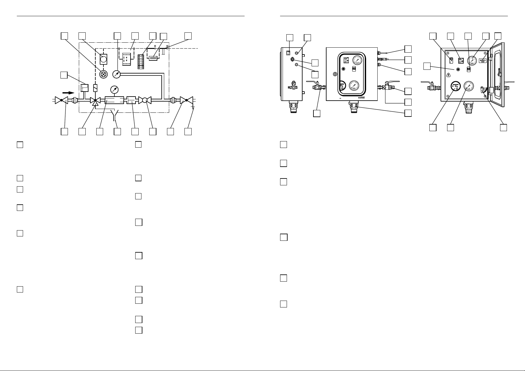
8. Funktionselemente
18 10 19 14 12
Allgemeine Hinweise
8
9
12 17
10 14 20 19
9
Prinzipskizze
2
000
3
m
1 3 5 11 4 6 7 21
1 Wasseranschluss am Absperrventil R 1/2
DIN 2999 oder Löttüllenanschluss ∅ 15
zum Anschluss an das öffentliche
Wasserversorgungsnetz
2 Wasserzähler
3 Umschaltventil - stromlos geschlossen -
zur Steuerung des Rohrtrenners
4 Zusätzlicher Rückflussverhinderer zur
Erhöhung des Trinkwasserschutzes in
heißwasserbeständiger Ausführung
5 Rohrtrenner R295SA-½’’ - Einbauart 2,
DVGW-bauteilgeprüft. Befindet sich
normalerweise in T rennstellung, Umsteuerung in Durchflussstellung nur,
wenn das Niveau im Ausdehnungsgefäß unter den unteren Wasserstand
absinkt.
6 Stelleinrichtung - umstellbar zum
Schnell- und Nachfüllen der Anlage.
Durchflussleistung variabel, entsprechend
der abgebildeten Füllkurven durch
einfache Verstellung der Drossel.
Während des vollautomatischen
Betriebes muss die Einstellung stets auf
„Nachfüllen“ vorgenommen werden.
7 Anlagenanschluss am Absperrventil R 1/2
DIN 2999 oder Löttüllenanschluss ∅ 15
zum Anschluss der nachgeschalteten
Anlage.
8 Klemmleiste - Zusammenführung der
einzelnen elektrischen Komponenten.
9 Summierzähler addiert die Anzahl der
Nachfüllvorgänge; mittels Schlüssel
rückstellbar.
10 Zeitrelais - Möglichkeit zur zeitlichen
Begrenzung des Füllvorganges,
variable Zeiteinstellungen
zwischen 6 - 60 min. Nachfüllzeit.
11 Ablauftrichter - zur Ableitung
geringer Wassermengen beim Umschaltvorgang. Anschluss von Kunst-
stoffrohr DN 40 möglich.
12 EIN-/AUS-Schalter
13 T auch-Elektrodenanschluss; Signalgeber
für unteren und oberen W asserstand.
14 Niveauwächter
15 Durchführungstülle für Leitwarten-
anschlusskabel.
11
14
Sens.k
C
MAX
MIN
B1
B2B3
R
13
U
15
1
16 Manometer - zeigt den Zulaufdruck des
V ersorgungsnetz es an.
17 Anschlusskabel zur Stromversorgung
des Nachfüllautomaten
18 Leuchtmeldetaster - leuchtet, wenn die
am Zeitrelais eingestellte Nachfüllzeit
überschritten wird. Der Nachfüllvorgang
wurde unterbrochen. Durch Eindrücken
des Tasters wird das Zeitrelais zurück-
gestellt, die Lampe erlischt und das
Gerät ist wieder betriebsbereit.
19 Manometer - zeigt den Systemdruck
der nachgeschalteten Anlage an. Für
genaue Einstellungen ist ein Feinmessmanometer in der Anlage bauseits
vorzusehen.
20 Sichtfenster zur Anzeige der Rohrtrenn-
erstellung
(grünes Feld sichtbar = Trennstellung).
21 Entleerungsventil - wird benötigt zur
einfacheren Einstellung der Druckgrenzwerte.
17
13
15
21
11
11
14
Sens.k
C
MAX
MIN
B1
B2B3
R
U
18
7
2 16 6
98
Page 6

Hinweise für Montage und Inbetriebnahme
Hinweise für die Veränderung der Füllzeit
Achtung!
Die Montage und Inbetriebnahme ist unter Zugrundelegung der einschlägigen Vorschriften nur durch Sachkundige durchzuführen.
Vom Betreiber ist eine Überstrom-Schutzeinrichtung in Form einer Sicherung mit Grenzwert 4 A / 250 V vorzusehen.
9. Montage und Inbetriebnahme
1. Gerät an der W and befestigen.
2. Wasserseitige Anschlüsse an das Trinkwassernetz bzw. an die Anlage herstellen. Für
spätere Servicearbeiten ist auf der Wasserzulaufseite ein Absperrventil und auf der
Anlagenseite ein Absperrventil vorzusehen.
3. Ablauftrichter mit Kunststoffrohr DN 40 verbinden.
4. Absperrventil der Anlagenseite öffnen.
5. Absperrventil der Wasserzulaufseite öffnen.
6. Hydraulische Anschlüsse am Gerät auf Dichtigkeit kontrollieren.
7. Die beiden Tauchelektroden in das Ausdehnungsgefäß mit einem Niveauunterschied
von ca. 200 mm installieren.
8. Massekabel (gehört nicht zum Lieferumfang) an das Ausdehnungsgefäß von außen
anbringen.
9. Elektrodenkabel mit Massekabel über V erbindungskabel an den Nachfüllautomaten
anschließen.
10. Elektrischen Anschluss herstellen.
11. Hebel für Schnellfüllen oder Nachfüllen einstellen. (Nach dem Füllvorgang ist die
Position „Nachfüllen“ einzustellen).
12. Zeiteinstellung am Zeitrelais kontrollieren.
10. Einstellung der Füllzeit am Zeitrelais
Das Zeitrelais 10 ist werkseitig eingestellt auf Merkziffer 2 (Laufzeit 12 min.).
1-10min
6-60min
6-60s
1-10h
1-10
10-100h
Leuchtdiode blinkt:
d.h. der Füllvorgang läuft.
Leuchtdiode brennt:
d.h. die eingestellte Nachfüllzeit
ist überschritten und der
Anlagedruck wurde nicht
erreicht.
Durch Verstellen des Rändelgriffes kann die Nachfüllzeit verändert werden.
0,1-1
Un
Merkziffer
min. Laufzeit
Das V erbindungskabel zwischen Ausdehnungsgefäß und Nachfüllautomaten,
max 1,5 mm
2
, 3-adrig, ist bauseits beizustellen.
Nach jedem Nachfüllvorgang geht die Zeitvorgabe auf die Ursprungseinstellung zurück.
10
11
14
Sens.k
C
MAX
MIN
B1
B2B3
R
U
1110
Page 7

Hinweise für die Überprüfung des Ein- und AusgangssignalsNiveau-Wächter
11. Niveau-Wächter
Der Niveau-Wächter ENS überwacht Füllstände leitfähiger Flüssigk eiten, z.B F risch- und
Abwasser. Mit seiner v ariablen Ansprechempfindlichkeit ist er auch für jedes andere leitfähige
Medium geeignet. Für Flüssigkeiten oder feuchte Schüttgüter stehen Stab- oder Seilelektroden
zur V erfügung.
Als Zweipunktregler steuert das Gerät mit den Elektroden MAX und MIN und dem
Massenanschluss C Pumpen oder V entile für die automatische Befüllung oder Entleerung von
Behältern. Dabei sind die Grenzen des zu regelnden Niveaus von der Anordnung der Elektroden MAX und MIN abhängig. Als Massenanschluss C kann auch die leitende Behälterwand
benutzt werden.
Tauchelektrode und Zubehör
EL 1 einpolige Elektrode 2 Stück
H 07 RN-F 1,5 mm
A1 11
15
C MAX MIN
ENS
mecotron
A1
11
Sens.k
R
U
2
(NSH 1,5 mm2) einadriges Kabel 2 Stück
1. Empfindlichkeit (P otentiometer)
Die Ansprechempfindlichkeit kann stufenlos eingestellt werden.
linker Potentiometeranschlag 5 kΩ
rechter Potentiometeranschlag 100 kΩ
Bei der Inbetriebnahme Potentiometer "Sens." auf den Minimal-
A2
12
14
1
C
MAX
MIN
B1
B2 B3
wert stellen.
Nach Benetzung von Elektrode MAX die Ansprechempfindlichkeit "Sens." in Richtung Maximalwert drehen, bis
Relais-Niveau anzieht. Relais fällt ab , wenn Elektroden MAX
und MIN sich außerhalb der Flüssigkeit befinden.
2
3
2. Relaisfunktion
Die LED leuchtet mit aktiviertem Relais.
12. Überprüfung des Ein- und Ausgangssignals
1. Gerät muss betriebsbereit sein.
2. Überprüfung des Eingangssignals zur Nachfüllung.
2.1 Hebel an Stelleinrichtung 6 auf "Nachfüllen" stellen.
2.2 Entleerungsventil 21 leicht öffnen, so dass der Systemdruck der nachgeschalteten
Anlage abfällt; erkennbar am Manometer 19 .
2.3 Bei Erreichen des unteren Niveaustandes wird der Rohrtrenner in Durchflussstellung
geschaltet (grünes Feld im Sichtfenster 20 nicht mehr sichtbar).
2.4 Entleerungsventil 21 langsam schließen.
2.5 Bei Erreichen des Ausschaltsignals geht der Rohrtrenner in Trennstellung.
19
11
14
Sens.k
C
MAX
MIN
B1
B2B3
R
U
18
20
21
11
14
Sens.k
C
MAX
MIN
B1
B2B3
R
U
6
3. Netzversorgung
Die leuchtende LED signalisiert die anliegende V ersorgungsspannung
A2141812
16
1312
Page 8

Hinweise für den Elektro-FachmannHinweise für die Behebung von Störungen
13. Störungsanzeige
Beim Aufleuchten der Leuchtmeldetaste 18 können folgende Ursachen vorliegen:
● Zeitvorgabe für das Gerät zum Erreichen des oberen Abschaltdruckes ist zu klein;
● im Heizungssystem liegt eine Leckstelle vor , so dass das Füllv olumen nicht erreicht wird.
14. Wartung
Inspektion: Rohrtrenner, Einbauart 2 und 3 alle 6 Monate
Inspektion: Rückflussv erhinderer , jährlich
Durchführung: Betreiber oder Installateur
15. Verdrahtungsplan
1514
Page 9

General Instructions
General Instructions
1. Construction
2. Purposes
Positions of the upper and
lower immersion
11
14
X
N
I
A
M
M
C
3
B
2
Sens.k
B
1
B
R
U
electrodes
200 mm
11
14
Sens.k
C
MAX
MIN
B1
B2B3
R
U
Shutoff valves on inlet and outlet
●
● Powder coated pressed steel housing
● Drinking water and system connection with either R ½” DIN 2999 shutoff valves
or 15 mm soldered.
● Fill counter - Totals the number of filling operations - with resetting key
● Time relay finely adjustable between 6 and 60 minutes to limit the filling time
● Fault indicator lamp and cut-out button
● Pressure gauges for inlet and system pressures
● Discharge tundish for connection to a DN 40 plastics pipe
● Two electrodes for detecting upper and lower water levels - each with four
metres of cable
● ON/OFF double-pole switch
● Electrical connection with plug 230V~/ 50/60 Hz
● One metre cable on appliance for electrode connection
● Bush for cable connection to a building management system
● Level sensors
● Water meter
●
Maintaining pressure between prescribed upper and lower limits in closed
heating and cooling systems
● Prevention of back flow, back syphonage or back pressure of the heating or
cooling water into the potable water network.
● Facility for fast and automatic refilling of the system
● Prevention of build up of steam in the system caused by loss of pressure
1716
Page 10

General Instructions
General Instructions
3. Scope of Application
The fully automatic NA228S-C refilling unit with its DV GW -approv ed component parts:
● R295SA-
● RV282-
permits permanent fixed connection of open heating systems to the drinking water
network. This applies par ticular ly to heating systems to DIN 4751, Sheet 1.
The following operating data applies for the downstream systems:
Maximum system pressure: 4.0 bar
Maximum temperature: 100 °C.
1
/2 backflow prev enter, DIN/DVGW No. 569VE
1
/2 check valve, DVGW No. 0572
4. Testing
The technical approvals of the NA228S-C fully automatic refill unit were obtained from TÜV
Bayern, Hessen, Sachsen, Südwest E.V. under No . AW-SEZ/408/97
The tests are based on the following DIN standards and worksheets:
● DIN 3266, Parts 1 and 2
● Tests for electrical and mechanical safety 1/EN 61010 - 1.3.1994 CE, low
voltage guidelines.
5. Technical Data
Refilling: Flow rate 110 litres/h at 2.0 bar differential pressure
Fast filling: Flow rate finely adjustable between 110 litres/h and
1100 litres/h at 2.0 bar differential pressure
Duration of fill: Adjustable between 6 and 60 minutes
(set at 12 minutes during manufacture)
Water level: Signal emission by immersion electrodes for upper and
lower water level limits.
Electrode Spacing: Approximately 200 mm
Water inlet pressure:Minimum 1.5 bar, maximum 4.0 bar
Supply voltage: 230V, 50/60 Hz
Supply voltage
for immersion
electrodes: 24 V
Electrical Load: 30 W
Dimensions: Height - 380 mm
Weight: Approximately 16 kg
~
50/60 Hz; at level monitor
Width - 370 mm
Depth - 160 mm
1918
Page 11

General InstructionsGeneral Instructions
6. Flow Diagrams
Filling curves
Fast filling
Flow rate V (litres/h)
∆p (bar)
Fast filling
Refilling
Setting
Flow rate V (litres/h)
∆p (bar)
Refilling
Fast filling
7. Method of Operation
5
10 3
13
A1 11
15
C MAX MIN
ENS
mecotron
A2
A1
12
11
14
Sens.k
C
MAX
MIN
B1
B2B3
R
U
A2141812
16
Refilling Refilling
The flow rate and therefore the filling time for
fast filling are dependent on the position of
the ball valve lev er.
At the end of the filling operation the position
of the ballvalve lever should be set to “Refill”.
An interlock prevents the appliance from
being closed if the lever is not in the “Refill”
position.
The refill volume can be checked by
comparing the before and after water meter
readings.
If the system pressure falls to below the lower set value, for example through leakage losses,
then an electrical impulse from the level switch 1 3 opens the changeover valve 3 and
thereby permits fluid flow to the backflow prev enter . The inlet pressure moves the backflow
preventer 5 to the flow position and the system is refilled until the level rises to the set upper
limit. The time period of the refill is controlled by the time relay 1 0 . Once the upper limit has
been reached, the level switch 1 3 closes the changeover valve 3 and the backflow
preventer goes to the shutoff position (open to atmosphere). The time relay then returns to the
outlet position.
If the inlet pressure falls to the operating pressure of the backflow preventer during the
automatic refilling operation, then the backflow preventer automatically goes to the shutoff
position (open to atmosphere). The shutoff position of the backflow preventer is indicated
in the viewing window (green visible = shutoff position)
2120
Page 12

General Instructions
8. Functional Elements
18 10 19 14 12
General Instructions
8
9
12 17
10 14 20 19
9
Schematic
Diagram
2
000
3
m
1 3 5 11 4 6 7 21
1 Water connection - R 1/2” shutoff valv e to
DN 2999 or 15 mm soldered. For
connection to the public water supply
main.
2 Water Meter
3 Changeover valve - normally closed -
for control of the backflow preventer.
4 Additional check valve in version for hot
water applications, for increased
protection of the drinking water.
5 R295SA-
1
/2” type 2 backflo w preventer ,
DV GW tested. Normally in shutoff
position. Changes over to the flow
position only when the level in the
expansion vessel falls below the lower
set limit.
6 Setting valve - adjustable for either fast
fill or refill of the system. Variable flow
quantity, corresponding to the cur ves
illustrated simply by adjustment of the
setting valve. During fully automatic
refilling operation, the setting must
always be on “Refill”.
7 System connection - R 1/2” shutoff valve
to DIN 2999 or 15mm soldered.
For connection of the downstream
system).
8 Terminal strip - for connecting the
individual electrical components.
9 Fill counter - Totals the number of filling
operations - Reset with a special key.
10 Time relay - To permit time limitation of
the filling cycle. Variable time settings
from 6 to 60 minutes filling time.
11 Discharge Tundish - for carrying away
small quantities of water during the
changeover operation. Connection for
DN 40 plastics pipe.
12 ON/OFF switch.
13 Connection for immersion electrodes -
Signal emitters for upper and lower
water levels.
14 Level monitor
15 Bush for cable connection to a building
maintenance system
11
14
Sens.k
C
MAX
MIN
B1
B2B3
R
13
U
15
1
16 Pressure gauge - indicates the inlet
pressure of the supply
17 Cable connection for electrical supply
to the NA228S automatic refilling unit
18 Illuminated indicator button - lights up
when the set refill period on the time
relay is exceeded. The refilling
operation is then interrupted. When the
button is pressed, the time relay is
reset, the lamp goes out and the
appliance is ready for service again.
19 Pressure gauge - Indicates the
pressure in the downstream system. To
make accurate settings, a high
sensitivity pressure gauge should be
fitted in the downstream system.
20 Viewing window for indicating the
operating position of the backflow
preventer
(green visible = shutoff position)
21 Shutoff valve - for shutting off the inlet
pressure from the supply and to the
system
17
13
15
21
11
11
14
Sens.k
C
MAX
MIN
B1
B2B3
R
U
18
7
2 16 6
2322
Page 13

Installation and Commissioning Instructions
Instructions for Changing the Filling Time
IMPORTANT:
Assembly and commissioning must only be carried out by specialists according to
regulations and codes of good practice.
The user should fit electrical overload protection of 250V/4A.
9. Installation and Commissioning
1. Fix appliance to the wall.
2. Make connections to the inlet main water supply and to the system. To enable
subsequent service work a shutoff valve should be fitted on the inlet
side and a shutoff and drain valve be fitted on the system side.
3. Connect the discharge tundish outlet with a DN 40 plastic pipe.
4. Open the shutoff valve on the system side.
5. Open the shutoff valve on the inlet side.
6. Check connections on the appliance for leakage.
7. Install the two immersion electrodes in the expansion vessel, with a height
difference of approximately 200 mm.
8. Connect an earth cable (not supplied) to the outside of the expansion vessel.
9. Connect the earth and electrode cables between the expansion vessel and
the automatic refilling unit
10. Make electrical supply connections.
11 . Set the lever for fast fill or refill (after filling, the lever should be set to “Refill”).
12. Check the time setting of the time relay .
The link cable (maximum 1.5mm² and three core) between the expansion vessel and
the automatic refilling unit is to be supplied by the installer.
10. Adjustment of the Filling Time on the Time Relay
The time relay 10 is set during manufacture to setting No 2 (running time 12 minutes)
Diode lamp is flashing, which
means the filling cycle is
underway.
Diode lamp is on, which
means the set filling time has
been exceeded and the
system pressure has not been
reached.
The refilling time can be adjusted by turning the knurled knob.
1-10min
6-60min
6-60s
1-10h
1-10
10-100h
0,1-1
Un
Indicator number
Running time
(minutes)
After each refilling operation the timing reverts to the original setting.
10
11
14
Sens.k
C
MAX
MIN
B1
B2B3
R
U
2524
Page 14

Instructions for Checking the Lower and Upper Level SignalsLevel Sensor
11. Level Sensor
The level sensor ENS monitors the upper and lower fill levels of a conductive fluid, for
example fresh or waste water . Its variable sensitivity means that it can also be used for other
mediums. Rod or wire electrodes are available for fluids or moist waste materials.
As a two-point regulator, via electrodes MAX and MIN in conjunction with earth connection C,
it controls pumps or valves for automatic filling or draining of storage v essels. The level range
to be controlled is therefore dependent on the relative positions of electrodes MAX and MIN.
The conductive wall of the storage vessel may be used as the earth connection C.
A1 11
15
C MAX MIN
ENS
mecotron
A1
11
Sens.k
R
U
A2
12
14
1
C
MAX
MIN
B1
B2 B3
2
3
1. Sensitivity
The response sensitivity can be continuously adjusted:
anti-clockwise potentiometer stop 5 kΩ
clockwise potentiometer stop 100 kΩ
While putting into operation, set potentiometer "Sens." to
minimum value.
After wetting the electrode MAX turn response sensivity "Sens."
to maximum value until relay level increases. Relay decreases,
when electrodes MAX and MIN are outside the liquid.
2. Relay function
The LED is illuminated when the relay is activated
12. Checking the Lower and Upper Level Signals
1. The appliance must be ready to operate.
2. T esting the lo wer lev el signal for refilling.
2.1 Set the lever on the setting valve 6 to “Refill”
2.2 Slightly open the drain valve 21 , so that the system pressure of the downstream
system falls (this can be checked on the pressure gauge 19 .
2.3 When the lower level is reached, the backflow preventer will go to the flow position
(green no longer showing in the indicator window).
2.4 Slowly close drain valve 21 .
2.5 When the upper level is reached, the backflow preventer goes to the shutoff position
(open to atmosphere).
19
11
14
Sens.k
C
MAX
MIN
B1
B2B3
R
U
18
20
21
11
14
Sens.k
C
MAX
MIN
B1
B2B3
R
U
6
3. Po wer supply
Illuminated LED indicates presence of supply voltage.
A2141812
16
2726
Page 15

Instructions for Maintenance and Fault Finding
Electrical Data
13. Fault Indication
If the illuminated indicator button lights up, the following faults may be present:
● Filling time setting for the appliance too short to allow upper limit to be reached.
● In a heating system leaks are present so that the filling volume is not reached.
14. Maintenance
Inspection: Backflow preventer, types 2 and 3 - every six months
Inspection: Check valve - once a year
Water meter: Recalibration - after six years
Carried out by:User or installer.
15. Wiring Diagram
2928
Page 16

Automation & Control Products
Honeywell AG Phone: (49) 6261 810
Hardhofweg Fax: (49) 6261 81309 www.honeywell.de/haustechnik
D-74821 Mosbach braukmann@honeywell.com http://europe.hbc.honeywell.com
MU1H-1519GE23 R0802
 Loading...