


NA 228 S-A
Einbau-Anleitung • Installation and operating instructions
4
6
2
bar
8
0
10
5
15
bar
6
1
0
vom Kaltwassernetz
N
I
L
S
S
Ä
R
G
h
220V~50Hz
Z 52
UW
SPX
6
9
9
1
Honeywell AG
Hardhofweg . D-74821 Mosbach
MU1H-1517GE23 R0901
EB-NA228S-A=C
Nachfüllautomat Typ: NA 228
TÜV / DVGW
230V ~
50/60 Hz
30 Watt
Nachfüllautomat
für geschlossene Heizungs-und Kühlanlagen
Automatic Refilling Unit
for closed heating or cooling systems

1. Ausführung 2. Aufgaben
4
N
I
L
S
S
Ä
R
G
h
z
0H
5
~
V
0
2
2
2
5
Z
W
U
v
o
m
K
a
l
t
w
a
s
s
e
r
n
e
t
z
SPX
6
9
9
1
t T
a
m
to
u
lla
fü
h
/ D
c
V
a
Ü
N
T
~
V
0
3
2
6
2
r
a
b
8
0
0
1
5
5
1
bar
6
1
0
8
2
2
A
: N
p
y
W
G
V
0
/6
0
5
tt
a
W
0
3
z
H
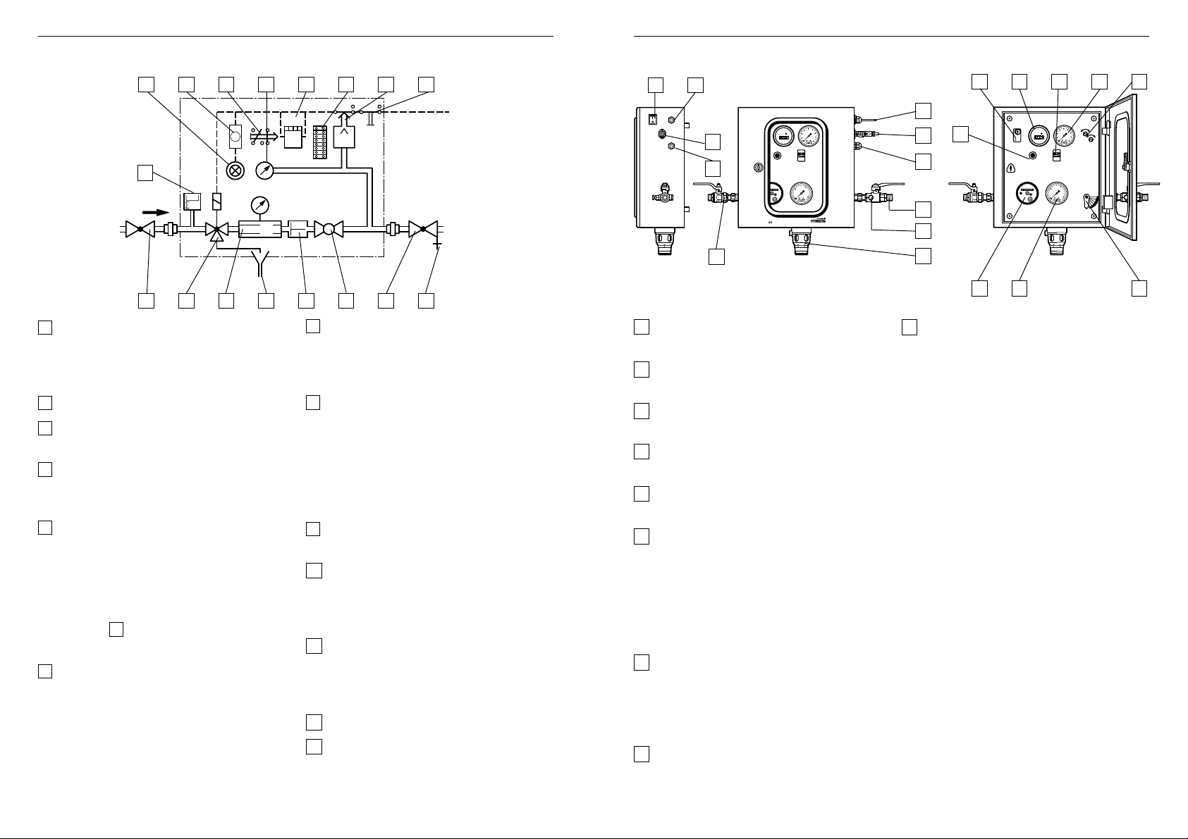
Einbaubeispiel
Allgemeine HinweiseAllgemeine Hinweise
● Ein- und ausgangsseitige Absperrung
● Gehäuse aus Stahlblech, pulverbeschichtet
● Trinkwasser- und Anlagenanschlußmit Absperrkugelhahn DIN 2999 R
1
/2'’ oder
Lötanschluß ∅ 15 mm
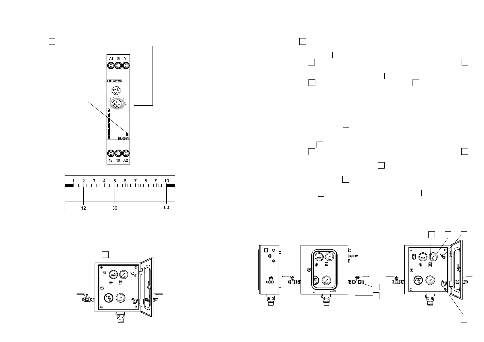
● Druckschalter für Ein- und Ausschaltdruck getrennt einstellbar
● elektronisches Zeitrelais stufenlos einstellbar zwischen 6-60 min. zur Begrenzung der
Fülldauer
● Meldeleuchte für Störfälle und Entriegelungstaste
● Manometer für Zulauf und Anlagendruck
● Ablauftrichter für Anschluß von Kunststoffrohr DN 40
● Gerätestecker für Fremdanschluß, potentialfrei über eingebauten Schütz
● EIN-/AUS-Schalter, 2-polig beleuchtet mit EIN-/AUS-Symbolen
● Elektrischer Anschluß 230 V~ / 50/60 Hz
● 1 m Anschlußkabel, nicht steckerfähig
● Wasserzähler: Anzeige in m³/h
● Durchführungstülle für Leitwartenanschlußkabel
● Betriebsstundenzähler
2 3
● Konstanthaltung des Systemdruckes in geschlossenen Heiz- und Kühlkreisläufen
zwischen vorgegebenen oberen und unteren Grenzwerten
● Verhinderung von Rückfließen, Rücksaugen oder Rückdrücken des Heiz- oder
Kühlwasser in das Trinkwassernetz
● Möglichkeit des Schnell- und automatischen Nachfüllens der Anlage
● Vermeidung von Dampfbildung durch Druckabfall im System.

Allgemeine HinweiseAllgemeine Hinweise
3. Verwendungsbereich
Der vollautomatische Nachfüllautomat NA 228 S-A mit seinen DVGW-bauteilgeprüften
Armaturen
● Rohrtrenner Typ: R 295 SA- ½, DIN-DVGW 569 VE
● Rückflußverhinderer Typ: RV 282- ½, DVGW -Nr . 0572,
● Wasserzähler T yp: E - T Qn 1,5 DNN.92
erlaubt eine ständige feste Verbindung von geschlossenen Heiz- und Kühlkreisläufen mit
der Trinkwasseranlage. Insbesondere gilt dies für geschlossene Heizungsanlagen nach
DIN 4751, Blatt 2, sowie für Anlagen nach DIN 4751, Blatt 3.
Für die nachgeschalteten Anlagen gelten folgende Betriebsdaten:
Anlagendruck max. = 6 bar
Temperatur max. = 120°C.
Bei Temperaturen über 100°C muß der Überdruck an der höchsten Stelle der Anlage in
kaltem Zustand mindestens 1 bar höher als der statische Anlagendruck sein (statische
Höhe + 1 bar).
5. T echnische Daten
Nachfüllen Volumenstrom 110 l/h bei ∆p = 2 bar
Schnellfüllen Volumenstrom stufenlos einstellbar zwischen 110 l/h und 1100 l/h
bei ∆p = 2 bar
Fülldauer Einstellbar 6 - 60 min.
(werkseitig eingestellt auf 12 min.)
Einschaltdruck Einstellbar 0,2 - max. 6 bar
(werkseitig eingestellt auf 1,2 bar)
Ausschaltdruck Einstellbar 0,5 - max. 6 bar
(werkseitig eingestellt auf 1,6 bar)
Schaltdifferenz 0,3 - 0,5 bar (druckabhängig)
Druck min. 3 bar; max. 6 bar
(über 6 bar muß ein Druckminderer vorgeschaltet werden)
Fremdanschluß Potentialfreier Kontakt, anschlußfertig verdrahtet, normal geöffnet;
schließt, wenn eingestellte Fülldauer überschritten wird.
Spannungsversorgung 230 V
Leistungsaufnahme 30 W
Abmessungen Höhe 380 mm
Gewicht ca. 16 kg
~
50/60 Hz
Breite 370 mm
Tiefe 160 mm
4. Prüfung
Die technischen Prüfungen des vollautomatischen Nachfüllautomaten NA 228 S-A
erfolgten durch den TÜV Bayern, Hessen, Sachsen, Südwest E.V. unter der
Prüf-Nr. A W-SEZ/408/97
Den Prüfungen liegen folgende DIN-Normen und Arbeitsblätter zugrunde:
● DIN 3266 Teil 1 / Teil 2
● Prüfungen zur elektrischen und mechanischen Sicherheit 1/EN61010 - 1.3.1994 CE
Niederspannungsrichtlinien
4 5

Allgemeine HinweiseAllgemeine Hinweise
6. Durchflußdiagramme
7. Funktionsbeschreibung
NETZ
EIN/AUS
Fremdanschluß
- potentialfrei -
5
zur Heizungsanlage
10 3 8
0 000 000 0
10
5
bar
15
0
16
Die Durchflußmenge bzw. die Fülldauer
beim Schnellfüllen ist abhängig von der
Stellung des Kugelhahnes.
Sinkt der Anlagendruck, z.B. durch Leckverluste, unter den eingestellten unteren Grenz-
Nach Beendigung des Füllvorgangs ist der
Hebel des Kugelhahnes auf die Stellung
„Nachfüllen“ einzustellen.
Eine Sperre in der Gerätetür verhindert,
daß das Gerät geschlossen werden kann,
wenn der Hebel sich nicht in der Position
„Nachfüllen“ befindet.
Aus dem Wasserzählerstand alt/neu kann
die Nachfüllmenge abgelesen werden.
wert des Anlagendrucks, so wird das Umschaltventil 3 über den Druckschalter 8 durch
elektrischen Impuls geöffnet und eine hydraulische Verbindung vom Wassernetz zum
Steuerkolben des Rohrtrenners hergestellt. Der Netzdruck steuert den Rohrtrenner 5 in
Durchflußstellung und die Anlage wird nachgefüllt bis zur Höhe des gewünschten Anlagendrucks . Die Zeitdauer des Nachfüllvorganges wird vom Zeitrelais 10 und vom
Betriebsstundenzähler erfaßt. Nach Erreichen des oberen Grenzwertes schließt der
Druckschalter 8 das Umschaltventil 3 , wodurch die Verbindung vom Wassernetz zum
Steuerkolben des Rohrtrenners wieder unterbrochen und gleichzeitig eine Verbindung
zur Atmosphäre hergestellt wird. Eine Feder schiebt nun den nicht mehr vom Netzdruck
belasteten Steuerkolben in Trennstellung. Das Zeitrelais geht zurück in die Ausgangsposition.
Fällt während des automatischen Nachfüllvorgangs der Netzdruck auf die Höhe des
Ansprechdrucks vom Rohrtrenner ab, so erfolgt der selbsttätige Öffnungsvorgang (Trennstellung) des Rohrtrenners. Die Trennstellung des Rohrtrenners ist im Sichtfenster als
grünes Feld zu erkennen.
6 7
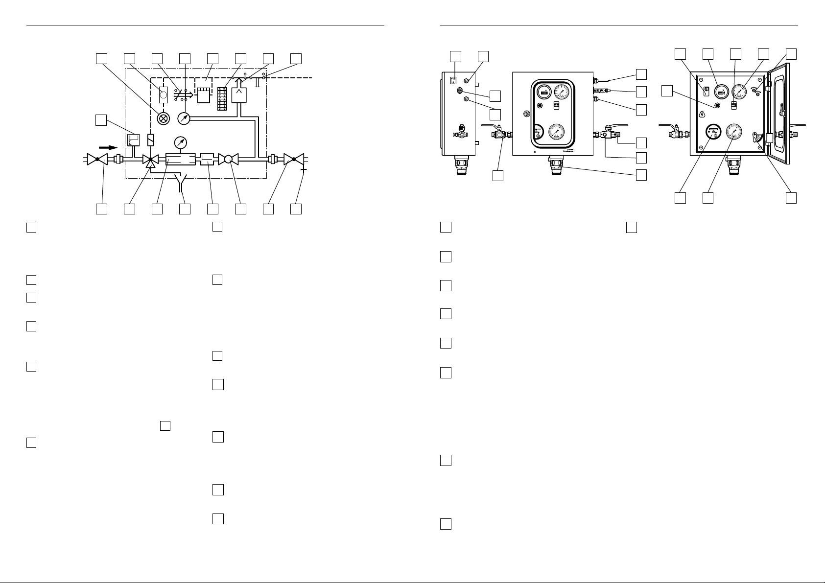
8. Funktionselemente
19 10 15 20 18 9 8 12
12 17
Allgemeine HinweiseAllgemeine Hinweise
10 18 21 20 8
Prinzipskizze
2
000
3
m
1 3 5 11 4 6 7 22
1 Wasseranschluß am Absperrventil R
DIN 2999 oder Löttüllenanschluß ∅ 15
zum Anschluß an das öffentliche
Wasserversorgungsnetz
2 Wasserzähler
3 Umschaltventil - stromlos geschlossen -
zur Steuerung des Rohrtrenners
4 Zusätzlicher Rückflußverhinderer zur
Erhöhung des Trinkwasserschutzes in
heißwasserbeständiger Ausführung
5 Rohrtrenner R295 S- ½’’ - Einbauart 2,
DVGW-bauteilgeprüft. Befindet sich
normalerweise in Trennstellung, Umsteuerung in Durchflußstellung nur,
wenn der Systemdruck der nachgeschalteten Anlage unter den am Druckschalter 8 eingestellten unteren
Grenzwert absinkt.
6 Stelleinrichtung - umstellbar zum
Schnell- und Nachfüllen der Anlage.
Durchflußleistung variabel, entsprechend
der abgebildeten Füllkurven durch
einfache Verstellung der Stelleinrichtung.
Während des vollautomatischen
Betriebes muß die Einstellung stets auf
„Nachfüllen“ vorgenommen werden.
P
1
7 Anlagenanschluß am Absperrventil R 1/2
/2
DIN 2999 oder Löttüllenanschluß ∅ 15
zum Anschluß der nachgeschalteten
Anlage.
8 Druckschalter - zur Veränderung des
Ein- und Ausschaltdruckes (unterer und
oberer Grenzwert), so daß jederzeit
eine Anpassung der Systemdrücke an
die jeweilige Anlage vorgenommen
werden kann. Erläuterungen über Verstellmöglichkeiten siehe Punkt 11.
9 Klemmleiste - Zusammenführung der
einzelnen elektrischen Komponenten.
10 Zeitrelais - Möglichkeit zur zeitlichen
Begrenzung des Füllvorganges,
variable Zeiteinstellungen
zwischen 6 - 60 min. Nachfüllzeit.
11 Ablauftrichter - zur Ableitung
geringer Wassermengen beim Umschaltvorgang. Anschluß von
Kunststoffrohr DN 40 möglich.
12 EIN-/AUS-Schalter mit Betriebsleuchte
13 Fremdanschluß - potentialfrei, z.B. für
externe Signalgeber (Schaltwarte)
NETZ
EIN/AUS
zur Heizungsanlage
Fremdanschluß
- potentialfrei -
13
14
h
Betriebsstunden Systemdruck
Entriegelung
serzähler
Nachfüllautomat Typ:NA 228
TÜV / DVGW
230V~ 50/60 Hz 30 W
4
6
2
bar
0
8
10
5
bar
15
0
16
Netzdruck
1
14 Durchführungstülle für Leitwarten-
anschlußkabel.
15 Schaltschütz für potentialfreien Fremd-
anschluß
16 Manometer - zeigt den Zulaufdruck des
Versorgungsnetzes an.
17 Anschlußkabel zur Stromversorgung
des Nachfüllautomaten
18 Betriebsstundenzähler - erfaßt die
Nachfüllzeiten.
19 Leuchtmeldetaster - leuchtet wenn die
am Zeitrelais eingestellte Nachfüllzeit
überschritten wird. Der Nachfüllvorgang
wurde unterbrochen. Durch Eindrücken
des Tasters wird das Zeitrelais zurück
gestellt, die Lampe erlischt und das
Gerät ist wieder betriebsbereit.
20 Manometer - zeigt den Systemdruck
der nachgeschalteten Anlage an. Für
genaue Einstellungen ist ein Feinmeß-
manometer in der Anlage bauseits
vorzusehen.
21 Sichtfenster zur Anzeige der Rohrtrenn-
erstellung
(grünes Feld sichtbar = Trennstellung).
17
4
6
2
13
14
19
7
Zeitrelais
h
Betriebsstunden Systemdruck
Entriegelung
bar
0
8
10
5
Schnellfüllen
bar
15
0
16
NetzdruckWasserzähler
2
Nachfüllen
22
11
2 16 6
22 Entleerungsventil
- wird benötigt zur einfacheren Einstellung der Druckgrenzwerte.
5
4
3
8 9

Hinweise für Montage und Inbetriebnahme
Hinweise für die Einstellung des Druckschalters
Achtung!
Die Montage und Inbetriebnahme ist unter Zugrundelegung der einschlägigen Vorschriften nur durch Sachkundige durchzuführen.
Vom Betreiber ist eine Überstrom-Schutzeinrichtung in Form einer Sicherung mit Grenzwert 10 A / 250 V vorzusehen.
9. Montage und Inbetriebnahme
1. Gerät an der Wand befestigen.
2. Wasserseitige Anschlüsse an das Trinkwassernetz bzw. an die Anlage herstellen. Für
spätere Servicearbeiten und zur leichteren Einstellung der Druckgrenzwerte ist auf der
Wasserzulaufseite ein Absperrventil und auf der Anlagenseite ein Absperrventil mit
Entleerungsventil diesem Gerät beigefügt.
3. Ablauftrichter mit Kunststoffrohr DN 40 verbinden.
4. Absperrventil der Anlagenseite öffnen.
5. Absperrventil der Wasserzulaufseite öffnen.
6. Hydraulische Anschlüsse am Gerät auf Dichtigkeit kontrollieren.
7. Hebel für Schnellfüllen oder Nachfüllen einstellen. (Nach dem Füllvorgang ist die
Position „Nachfüllen“ einzustellen).
8. Zeiteinstellung am Zeitrelais kontrollieren.
9. Elektrischen Anschluß herstellen.
10. Grundeinstellung des Druckschalters
Der Druckschalter ist werkseitig eingestellt auf die Werte:
Einschaltdruck = 1,2 bar
Ausschaltdruck = 1,6 bar
Schaltdifferenz = 0,4 bar
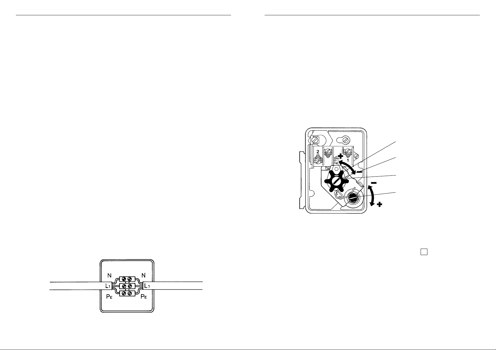
11. Veränderung der Druckeinstellungen
Das Handrad kann durch Umstecken für die
Veränderung des Ein- und Ausschaltdruckes
verwendet werden.
ACHTUNG!
Der Ausschaltdruck ist stets zuerst zu
verstellen.
Der max. Ausschaltdruck muß niedriger
sein als der Schließdruck des in der
Anlage installierten Sicherheitsventiles.
Der Aus-schaltdruck muß mindestens 0,3 0,5 bar höher sein als der Einschaltdruck.
a) Veränderung des Ausschaltdruckes
durch Korrektur an der Stellschraube SA
am Druckschalter 7 in Drehrichtung
„+“ (=höherer Ausschaltdruck) oder
„-“ (niedrigerer Ausschaltdruck).
b) Veränderung des Einschaltdruckes
durch Korrektur an der Stellschraube SE
am Druckschalter 7 in Drehrichtung
„+“ oder „-“.
c) Eine eventuelle Veränderung des Aus-
und Einschaltdruckes darf nur bei
Betrieb der Anlage durchgeführt
werden.
Handrad
Stellschraube für
Ausschaltdruck (SA)
1 Umdrehung ~ 0,5 bar
Stellschraube für
Einschaltdruck (SE)
10 11
Hinweise für die Überprüfung der FunktionHinweise für die Veränderung der Füllzeit
12. Einstellung der Füllzeit am Zeitrelais
Das Zeitrelais 10 ist werkseitig eingestellt auf Merkziffer 2 (Laufzeit 12 min.).
1-10m/h
6-60min
Leuchtdiode blinkt:
d.h., der Füllvorgang läuft.
Leuchtdiode brennt :
d.h., die eingestellte Nachfüllzeit ist überschritten und der
Anlagedruck wurde nicht
erreicht.
Durch Verstellen des Rändelgriffes kann die Nachfüllzeit verändert werden.
6-60
1-10h
1-10
10-100h
0,1-1
Un
Merkziffer
min. Laufzeit
13. Überprüfung des Aus- bzw. Einschaltdruckes
1. Absperrventil 7 schließen.
2. Überprüfung bzw. Einstellung des Ausschaltdruckes
2.1Hebel an Stelleinrichtung 6 auf Nachf üllen stellen.
2.2Entleerungsventil 22 leicht öffnen, so daß Druck abfällt; erkennbar am Manometer 20
2.3Bei Erreichen des eingestellten Einschaltdruckes wird der Rohrtrenner in Durchfluß-
stellung geschaltet grünes Feld im Sichtfenster 21 nicht mehr sichtbar .
2.4Entleerungsventil 22 langsam schlie ßen, so daß Manometer 20 einen langsamen
Druckanstieg zeigt.
2.5Bei Erreichen des Ausschaltdruckes geht der Rohrtrenner in Trennstellung und der
Druck beginnt wieder zu sinken. Der Umkehrpunkt zwischen Druckan- und abstieg ist
der Ausschaltdruck.
2.6Soll der Ausschaltdruck ver ändert werden, so muß eine Korrektur an der Stellschraube SA am Druckschalter 8 in Drehrichtung + oder - vorgenommen werden.
1 Umdrehung entspricht einer Veränderung von ca. 0,5 bar.
3. Überprüfung bzw. Einstellung des Einschaltdruckes
3.1Hebel am Kugelhahn 6 auf Nachfüllen stellen.
3.2Entleerungsventil 22 leicht öffnen, so daß Druck abfällt; erkennbar am Manometer 20
3.3Bei Erreichen des eingestellten Einschaltdruckes wird der Rohrtrenner in Durchfluß-
stellung geschaltet grünes Feld im Sichtfenster 21 nicht mehr sichtbar .
3.4Soll der Einschaltdruck verändert werden, so ist eine Korrektur an der Stellschraube SE am Druckschalter 8 in Drehrichtung + oder - vorzunehmen. Eine
Umdrehung entspricht einer Veränderung von ca. 0,5 bar .
3.5Nach der Einstellung des Druckschalters ist das Entleerungsventil 22 zu schließen
und das Absperrventil 7 zu öffnen.
ACHTUNG: Der Ausschaltdruck ist stets zuerst zu verstellen.
Nach jedem Nachfüllvorgang geht die Zeitvorgabe auf die Ursprungseinstellung zurück.
10
4
6
2
h
bar
0
Zeitrelais
8
Betriebsstunden Systemdruck
Entriegelung
10
5
Schnellfüllen
bar
15
0
16
5
NetzdruckWasserzähler
4
3
2
Nachfüllen
12 13
NETZ
EIN/AUS
zur Heizungsanlage
Fremdanschluß
- potentialfrei -
h
Betriebsstunden Systemdruck
Entriegelung
serzähler
Nachfüllautomat Typ:NA 228
TÜV / DVGW
230V~ 50/60 Hz 30 W
21 20 8
4
6
2
bar
0
8
10
5
bar
15
0
16
Netzdruck
7
Zeitrelais
h
Betriebsstunden Systemdruck
Entriegelung
4
6
2
bar
0
8
10
5
Schnellfüllen
bar
15
0
16
5
NetzdruckWasserzähler
4
3
2
Nachfüllen
22
6

Hinweise für den Elektro-FachmannHinweise für die Behebung von Störungen
14. Störungsanzeige
Beim Aufleuchten der Leuchtmeldetaste können folgende Ursachen vorliegen:
● Zeitvorgabe für das Gerät zum Erreichen des oberen Abschaltdruckes ist zu klein;
● im Heizungssystem liegt eine Leckstelle vor, so daß der Ausschaltdruck nicht
erreicht wird.
15. Wartung
Inspektion: Rohrtrenner, Einbauart 2 und 3 alle 6 Monate
Inspektion: Rückflußverhinderer, jährlich
Durchführung: Betreiber oder Installateur
16. V er drahtungsplan
14 15

1. Construction 2. Purposes
4
N
I
L
S
S
Ä
R
G
h
220V~50Hz
UWZ 52
vom
K
a
ltw
ass
ernetz
SPX
6
9
9
1
6
2
bar
8
0
10
5
5
1
bar
6
1
0
General Instructions General Instructions
Nachfüllautomat Typ: NA 228
TÜV / DVGW
230V ~
50/60 Hz
30 Watt
● Shutoff valves on inlet and outlet
● Powder coated pressed steel housing
● Drinking water and system connection either with R
1
/2” shutoff
valve to DN 2999 or 15 mm soldered.
● Pressure switch for cut-in and cut-out pressure separately adjustable
● Electronic time relay finely adjustable between 6 and 60 minutes to limit
the filling time
● Fault indicator lamp and cut-out button
● Pressure gauges for inlet and system pressures
● Discharge tundish for connection to a DN 40 plastics pipe
● Electrical plug for remote connection, voltage-free via integral fuse
● ON/OFF switch, double pole and with ON/OFF illuminated symbols
● Electrical connection 230V~50/60 Hz
● One metre connection cable without plug
● Water meter: Indicates in m
● Bush for cable connection to a building management system
● Operating-time indicator
3
/h
16 17
Installation Example
● Maintaining pressure between prescribed upper and lower limits in closed
heating and cooling systems
● Prevention of back flow, back syphonage or back pressure of the heating or
cooling water into the potable water network
● Possibility for fast and automatic refilling of the system
● Prevention of build up of steam in the system caused by loss of pressure

General InstructionsGeneral Instructions
3. Scope of Application
The fully automatic NA 228 S-A refilling unit with its DVGW-approved component parts:
● R 295 SA -
● RV 282 -
● Type E-T Qn 1.5 DNN.92 water meter
permits permanent fixed connection of closed heating and cooling systems to the drinking
water system. In particular this applies for closed heating systems to DIN 4751, Sheet 2
and for systems to DIN 4751 Sheet 3.
The following operating data applies for the downstream systems:
Maximum system pressure: 6.0 bar
Maximum temperature: 120 °C
For temperatures above 100 °C, the pressure at the highest point in the system when the
system is cold must be at least 1.0 bar above the operating pressure
(static height plus 1.0 bar).
1
/2 backflow preventer, DIN-DVGW 569 VE
1
/2 check valve, DVGW No. 0572
4. Approvals
5. T echnical Data
Refilling: Flow rate 110 litres/h at 2.0 bar differential pressure
Fast filling: Flow rate finely adjustable between 110 litres/h and
1100 litres/h at 2.0 bar differential pressure
Duration of fill: Adjustable between 6 and 60 minutes
(set at 12 minutes during manufacture)
Cut-in pressure: Adjustable between 0.2 and 6.0 bar maximum
(set at 1.2 bar during manufacture)
Cut-out pressure: Adjustable between 0.5 and 6.0 bar maximum
(set at 1.6 bar during manufacture)
Pressure switching
differential: 0.3 to 0.5 bar (depending on pressure)
Pressure: Minimum 3.0 bar, maximum 6.0 bar
(a pressure reducing valve must be fitted before the
refilling unit for pressures above 6.0 bar)
Remote connection: Volt-free contact, connected ready for wiring, normally open,
closes when preset filling time is exceeded.
Supply voltage: 230V ~ 50/60 Hz
Electrical load: 30 W
Dimensions: Height - 380 mm
Width - 370 mm
Depth - 160 mm
Weight: Approximately 16 kg
The technical approvals of the NA 228 S-A fully automatic refill unit were obtained from
TÜV Bayern, Hessen, Sachsen, Südwest E.V. under No. AW-SEZ/408/97
The tests are based on the following DIN standards and worksheets:
● DIN 3266 Parts 1 and 2
● Tests for electrical and mechanical safety 1/EN 61010-1.3.1994 E, low
voltage guidelines
18 19

General InstructionsGeneral Instructions
6. Flow Diagrams
Filling curves
Fast filling
Flow rate V (litres/h)
∆p (bar)
Fast filling
Setting
Refilling
Refilling
Flow rate V (litres/h)
∆p (bar)
Fast filling
7. Method of Operation
NETZ
EIN/AUS
Fremdanschluß
- potentialfrei -
zur Heizungsanlage
10 3 8
5
0 000 000 0
10
5
bar
15
0
16
Refilling Refilling
The flow rate and therefore the filling time
for fast filling are dependent on the position
of the ball valve lever.
At the end of the filling operation the
position of the ballvalve lever should be set
to “Refill”.
An interlock prevents the appliance from
being closed if the lever is not in the “Refill”
position.
The refill volume can be checked by
comparing the before and after water meter
readings.
If the system pressure falls to below the lower set value, for example through leakage losses,
then an electrical impulse opens the changeover valve 3 above the pressure switch 8 and
thereby permits fluid flow to the backflow preventer. The inlet pressure moves the backflow
preventer 5 to the flow position and the system is refilled until the pressure rises to the upper
set limit. The time period of the refill is monitored by the time relay 10 and the operating time
indicator. Once the upper limit value has been reached, the pressure switch 8 closes the
changeover valve 3 and the backflow preventer 5 goes to the shutoff position (open to
atmosphere). The time relay then returns to the outlet position.
If the inlet pressure falls to the operating pressure of the backflow preventer 5 during the
automatic refilling operation, then the backflow preventer automatically goes to the shutoff
position (open to atmosphere). The shutoff position of the backflow preventer is indicated in
the viewing window (green visible = shutoff position)
20 21
General InstructionsGeneral Instructions
8. Functional Elements
19 10 15 20 18 9 8 12
Schematic diagram
2
000
3
m
1 3 5 11 4 6 7 22
1 Water connection - R½” shutoff valve to
DIN 2999 or 15mm soldered. For
connection to the public water supply
main.
2 Water meter.
3 Changeover valve - normally closed -
for control of the backflow preventer.
4 Additional check valve in version for hot
water applications, for increased
protection of the drinking water.
5 R 295 S-
DVGW tested. Normally in shutoff
position. Changes over to the flow
position only when the downstream
system pressure falls below the lower
set limit on the pressure switch 8 .
6 Setting valve - adjustable for either fast
fill or refill of the system. Variable flow
quantity, corresponding to the curves
illustrated simply by adjustment of the
setting valve. During fully automatic
refilling operation, the setting must
always be on “Refill”.
1
/2” type 2 backflow preventer,
P
7 System connection - removable R 1/2”
shutoff valve to DIN 2999 or 15mm
soldered. For connection of the
downstream system.
8 Pressure switch - for changing the cut-in
and cut-out pressures (lower and upper
limits), so that they can always be set to
suit the system pressures. For further
information on setting options, please
see section 11.
9 Terminal strip - for connecting the
individual electrical components.
10 Time relay - To permit time limitation of
the filling cycle.
V ariable time settings from 6 to
60 minutes filling time.
11 Discharge tundish - for carrying away
small quantities of water during the
changeover operation. Connection for
DN 40 plastics pipe.
12 ON/OFF switch with operating indicator
lamps.
13 Remote connection - volt free, for
example for external signal emitter
(circuit monitor)
12 17
NETZ
EIN/AUS
zur Heizungsanlage
Fremdanschluß
- potentialfrei -
13
14
h
Betriebsstunden Systemdruck
Entriegelung
serzähler
Nachfüllautomat Typ:NA 228
TÜV / DVGW
230V~ 50/60 Hz 30 W
4
6
2
bar
0
8
10
5
bar
15
0
16
Netzdruck
1
14 Bush for cable connection to a building
maintenance system
15 Circuit fuse protection for volt-free
remote connection
16 Pressure gauge - indicates the inlet
pressure of the supply mains
17 Cable connection for electrical supply to
the automatic refilling unit
18 Operating time indicator - monitors the
refilling times
19 Illuminated indicator button - lights up
when the set refill period on the time
relay is exceeded. The refilling operation
is then interrupted. When the button is
pressed, the time relay is reset, the lamp
goes out and the appliance is ready for
service again.
20 Pressure gauge - Indicates the pressure
in the downstream system. To make
accurate settings, a high sensitivity
pressure gauge should be fitted in the
downstream system.
21 Viewing window for indicating the ope-
rating position of the backflow preventer
(green visible = shutoff position)
10 18 21 20 8
17
4
6
2
13
14
7
19
Zeitrelais
h
Betriebsstunden Systemdruck
Entriegelung
bar
0
8
10
5
Schnellfüllen
bar
15
0
16
5
NetzdruckWasserzähler
4
3
2
Nachfüllen
22
11
2 16 6
22 Drain valve - required for easy setting of
the pressure limits.
22 23
Installation and Commissioning Instructions
Instructions for Setting the Pressure Switch
IMPORTANT:
Assembly and commissioning must only be carried out by specialists according to
regulations and codes of good practice.
The user should fit electrical overload protection of 250V/10A.
9. Installation and Commissioning
1. Fix appliance to the wall.
2. Make connections to the inlet main water supply and to the system. To enable subsequent service work and simplify setting of pressure limits, a shutoff valve should be
fitted on the inlet side and a shutoff and drain valve be fitted on the system side.
3. Connect the discharge tundish with a DN 40 plastic pipe.
4. Open the shutoff valve on the system side.
5. Open the shutoff valve on the mains inlet side.
6. Check connections on the appliance for leakage.
7. Set the lever for fast filling or refilling (after filling, this should be set to the
“Refill” position).
8. Check the time setting of the time relay.
9. Make electrical connections.
10. Initial Pressure-Switch Settings
The pressure switch is set during manufacture to the following values:
Cut-in pressure: 1.2 bar
Cut-out pressure: 1.6 bar
Pressure differential: 0.4 bar
11. Changing the Pressure Settings
Handwheel
Adjuster screw for cutout pressure (SA)
One rotation ~ 0.5 bar
Setting screw for cut-in
pressure (SE)
Cable
from NA228
Connector board
24 25
Mains Cable
The hand wheel can be transferred and
used for changing both the cut-in and cutout pressure settings.
IMPORTANT:
The cut-out pressure must be adjusted first.
The maximum cut-out pressure must be
lower than the opening pressure of the
safety valve fitted to the system. The cut-out
pressure must be at least 0.3 to 0.5 bar
higher than the cut-in pressure.
(a)The cut-out pressure is changed by
turning the adjuster screw SA on the
pressure switch 7 . Turning in the
“+”direction increases the cut-out
pressure and “-” lowers it.
(b)The cut-in pressure is changed by
turning adjuster screw SE “+” to
increase and “-” to decrease.
(c) Any adjustment of the settings can only
be made with the system in operation.

Instructions for checking the operating functionsInstructions for Changing the Filling Time
12. Adjustment of the Filling Time on the Time Relay
The time relay is set during manufacture to setting No 2 (running time 12 minutes).
Diode lamp is flashing, which
means the filling cycle is
underway.
Diode lamp is on, which
means the set filling time has
been exceeded and the
system pressure has not been
reached.
The refilling time can be adjusted by turning the knurled knob.
1-10m/h
6-60min
6-60
1-10h
1-10
10-100h
0,1-1
Un
Indicator number
Running time
(minutes)
13. Checking the Cut-out and Cut-in Pressures
1. Close shutoff valve 7 .
2. Checking or setting the cut-out pressure.
2.1Set the lever on the setting valve 6 to the refilling position.
2.2 Slightly open the drain valve 22 so that the pressure indicated on the pressure
gauge 20 reduces.
2.3 On reaching the set cut-in pressure the backflow preventer will go to the flow position
(green no longer visible in the viewing window 21
2.4 Slowly close the drain valve 22 so that the pressure gauge 20 indicates a slow
increase in pressure.
2.5 When the cut-out pressure is reached the backflow preventer changes over to the
shutoff position and the pressure begins to fall again. The changeover point between
pressure rise and fall is the cut-out pressure.
2.6 If the cut-out pressure is to be changed, then the adjustment is made by turning the
adjuster screw SA on the pressure switch 8 in the “+” or “-” direction. One rotation is
equal to a change of approximately 0.5 bar.
3. Checking or setting the cut-in pressure.
3.1Set the lever on the setting valve 6 to the refilling position.
3.2Slightly open the drain valve 22 so that the pressure indicated on the pressure
gauge 20 reduces.
3.3 On reaching the set cut-in pressure the backflow preventer will go to the flow position
(green no longer visible in the viewing window 21
3.4 If the cut-in pressure is to be altered, then the adjustment is made by turning the
adjuster screw SE on the pressure switch 8 in the “+” or “-” direction. One rotation is
equal to a change of approximately 0.5 bar.
3.5 After setting the pressure switch, close drain off valve 22 and open shutoff valve 7 .
IMPORT ANT: The cut-out pressure must be adjusted first.
After each refilling operation the timing reverts to the original setting.
10
4
6
2
h
bar
0
Zeitrelais
8
Betriebsstunden Systemdruck
Entriegelung
10
5
Schnellfüllen
bar
15
0
16
5
NetzdruckWasserzähler
4
3
2
Nachfüllen
26 27
NETZ
EIN/AUS
zur Heizungsanlage
Fremdanschluß
- potentialfrei -
h
Betriebsstunden Systemdruck
Entriegelung
serzähler
Nachfüllautomat Typ:NA 228
TÜV / DVGW
230V~ 50/60 Hz 30 W
21 20 8
4
6
2
bar
0
8
10
5
bar
15
0
16
Netzdruck
7
Zeitrelais
h
Betriebsstunden Systemdruck
Entriegelung
4
6
2
bar
0
8
10
5
Schnellfüllen
bar
15
0
16
5
NetzdruckWasserzähler
4
3
2
Nachfüllen
22
6
Electrical DataInstructions for Maintenance and Fault Finding
14. Fault Indication
If the illuminated indicator button lights up, the following faults may be present:
● Filling time setting for the appliance too short to allow upper pressure
switch limit to be reached.
● In a heating system leaks are present so that the cut-out pressure is not
reached.
15. Maintenance
Inspection: Backflow preventer, types 2 and 3 - every six months
Inspection: Check valve - once a year
Water meter: Recalibration - after six years
Carried out by: User or installer.
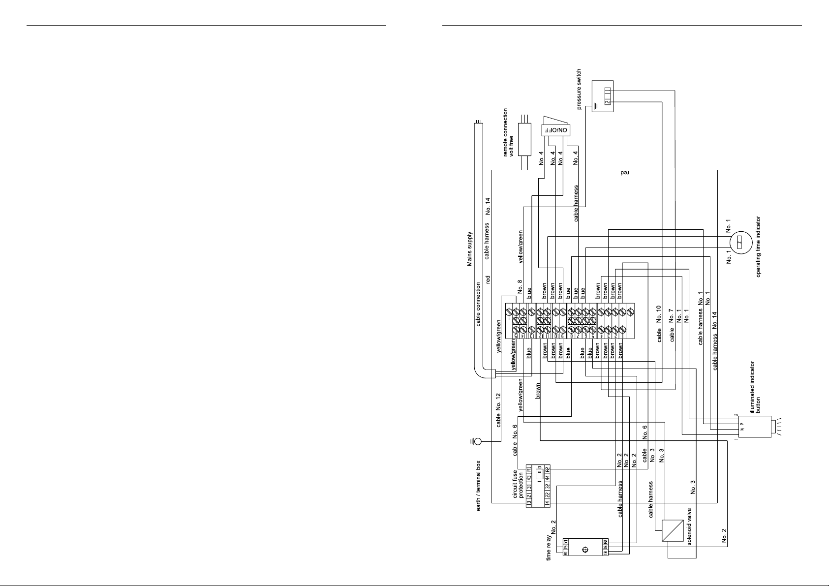
16. Wiring Diagram
28 29
 Loading...