

Page 1
NA 225 - A
Einbau-Anleitung ·
a
s
w
t
s
l
e
a
r
D
K
I
N
R 295 SA
EA 2
-
D
2
r
b
a
V
G
W
10
5
r
15
a
b
0
6
1
Installation instructions
Nachfüllstation
Typ: NA225-A
CE
230V
50 / 60 HZ
20W IP65
1
0
1
0
0
1
0
1
EB-NA225-A=B
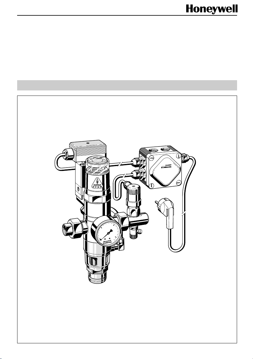
Nachfüllstation
Automatic refilling unit
1
Page 2
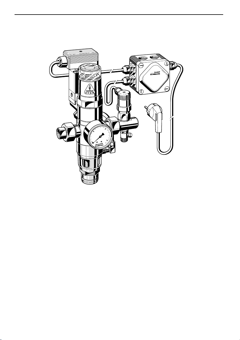
1. Ausführung
1. Construction
a
s
w
t
s
l
e
a
r
D
K
I
N
R 295 SA
EA 2
-
D
2
r
b
a
V
G
W
10
5
r
15
a
b
0
6
1
● Trinkwasser- und Anlagenanschluß mit
Gewindeanschluß nach DIN 2999 R
1
/2"
● Druckschalter für Ein- und Ausschalt-
druck einstellbar
● elektronisches Zeitrelais einstellbar
zwischen 0,5 s - 10 h zur Begrenzung
der Fülldauer
● Entleerungsventil für eventuelle Verän-
derung des Ein- oder Ausschaltdrucks
● Manometer für Zulaufdruck
● Ablauftrichter für Anschluß von
Kunststoffrohr DN 40
● Elektrischer Anschluß 230 V~ / 50/60 Hz
● 1 m Anschlußkabel, steckerfähig
Nachfüllstation
Typ: NA225-A
CE
230V
50 / 60 HZ
20W IP65
1
0
1
0
0
1
0
1
●
Drinking water and system - R1/2"
threaded connections to DIN 2999
●
Adjustable pressure switch for cut-in
and cut-out pressure
●
Electronic time relay finely adjustable
between 5 seconds and 10 hours to
limit the filling time
●
Drainoff valve for changing the cut-in or
cut-out pressure
●
Pressure gauge for inlet pressure
●
Discharge tundish for connection to a
DN 40 plastics pipe
●
Electrical connection 230V~50/60 Hz
●
One metre connection cable with plug
2
Page 3
2. Aufgaben
10
5
15
0
16
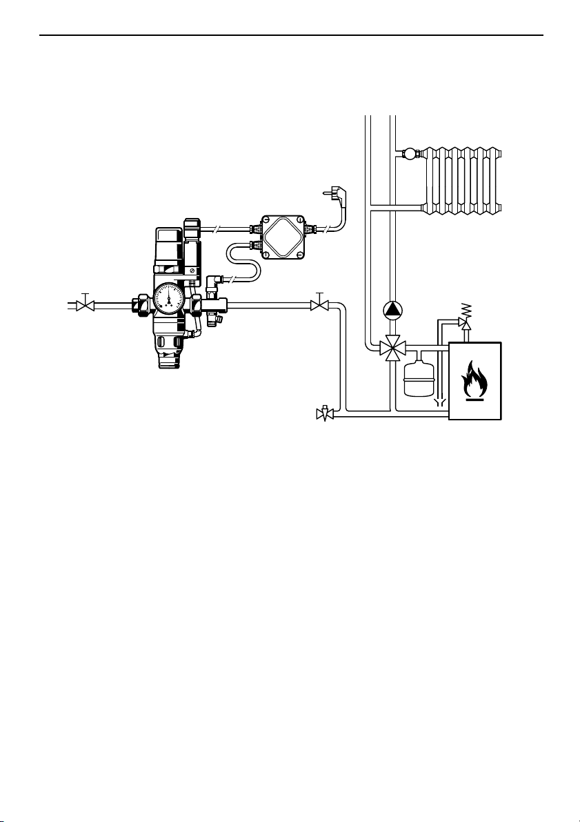
Einbaubeispiel (Heizungsanlage)
Installation example (heating system)
2. Purposes
● Konstanthaltung des Systemdruckes in
geschlossenen Heiz- bzw. Kühlkreis-
läufen zwischen vorgegebenen oberen
und unteren Grenzwerten
● Verhinderung von Rückfließen, Rück-
saugen oder Rückdrücken des Heizbzw. Kühlwassers in das Trinkwassernetz
● Begrenzung der Nachfüllzeit
● Vermeidung von Dampfbildung durch
Druckabfall im System.
●
Maintaining of constant system pressure
between predetermined upper and
lower limits in closed heating or cooling
circulation systems
●
Prevention of backflow, back syphonage
or back pressures of the heating or
cooling water into the drinking water
supply network
●
Limitation of the filling time
●
Prevention of steam generation caused
by pressure drop in the system
3
Page 4

3. Verwendungsbereich
Die Nachfüllstation NA 225 A mit ihren
DVGW-bauteilgeprüften Armaturen
● Rohrtrenner Typ: R 295 SA- ½, DIN-
DVGW 569 VE
● Rückflußverhinderer Typ: RV 282- ½,
DVGW-Nr. 0572
erlaubt eine ständige feste Verbindung von
geschlossenen Heiz- bzw. Kühlkreisläufen
mit der Trinkwasseranlage. Insbesondere
gilt dies für geschlossene Heizungsanlagen nach DIN 4751, Blatt 2, sowie für
Anlagen nach DIN 4751, Blatt 3.
Für die nachgeschalteten Anlagen gelten
folgende Betriebsdaten:
Anlagendruck max. = 4 bar
Wassertemperatur an der
Nachfüllstation max. = 40 °C.
3. Scope of Application
The fully automatic NA 225 A refilling unit
with its DVGW-approved component parts:
●
R 295 SA - 1/2 backflow preventer, DINDVGW 569 VE
●
RV 282- ½ check valve, DVGW No. 0572
enables permanent fixed connection of
closed heating or cooling systems to the
drinking water network. In particular this
applies for closed heating systems to DIN
4751, Sheet 2 and for systems to DIN 4751
Sheet 3.
The following operating data applies for
the downstream systems:
System pressure: Maximum 4.0 bar
Temperature at the
refilling unit: Maximum 40 °C.
4. Technische Daten
Nachfüllen Volumenstrom
110 l/h bei ∆p = 2 bar
Fülldauer Einstellbar 0,5 s - 10 h
(werkseitig eingestellt
auf 10 min)
Einschaltdruck 2,5 bar
(werkseitig eingestellt)
Ausschaltdruck 2,8 bar
(werkseitig eingestellt)
Schaltdifferenz 0,3 bar
Wasserzulaufdruck min. 3 bar; max. 4 bar
(über 4 bar muß ein
Druckminderer vorge-
schaltet werden)
Spannungs-
~
versorgung 230 V
Leistungsaufnahme 30 W
Abmessungen Höhe 285 mm
Gewicht ca. 2,9 kg
50/60 Hz
Breite 188 mm
Tiefe 65 mm
4. Technical Data
Refilling: Flow rate
110 litres/h at 2.0 bar
differential pressure
Duration of fill: Adjustable between
0.5 seconds and 10
hours (set at 10 minutes
during manufacture)
Cut-in pressure: 2.5 bar
(set during manufacture)
Cut-out pressure: 2.8 bar
(set during manufacture)
Pressure switching
differential: 0.3 bar
Water inlet
pressure: Minimum 3.0 bar,
maximum 4.0 bar (a
pressure reducing valve
must be fitted before
the refilling unit for
pressures above 4.0 bar)
~
Electrical supply: 230 V
Electrical load: 30 W
Dimensions: Height 285 mm
Width 188 mm
Depth 65 mm
Weight: Approximately 2.9 kg
50/60 Hz
4
Page 5
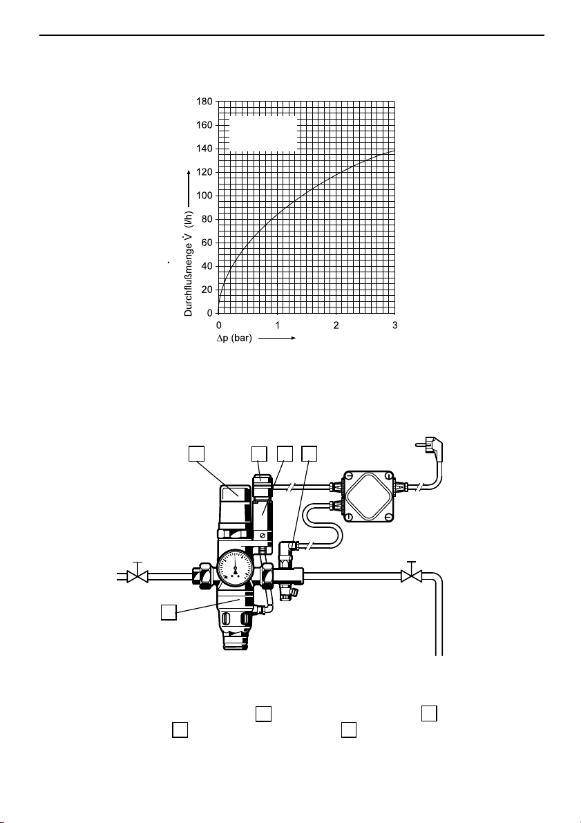
5. Durchflußdiagramm
(Wasser)
Flow rate V (litres/h)
5. Flow Diagram (water)
Nachfüllen
Refilling
6. Funktionsbeschreibung
10
5
15
0
16
5
Sinkt der Anlagendruck, z.B. durch Leckverluste, unter den eingestellten unteren
Grenzwert, so wird das Umschaltventil 3
über den Druckschalter 8 durch elektrischen Impuls geöffnet und gibt dadurch
den hydraulischen Zulauf zum Rohrtrenner
frei.
6. Method of Operation
87
310
If the system pressure falls to below the lower
set value, then an electrical impulse opens
the changeover valve
switch
8
and thereby permits fluid flow to
the backflow preventer.
5
3
above the pressure
Page 6

Der Zulaufdruck steuert den Rohrtrenner 5
in Durchflußstellung, die Anlage wird
nachgefüllt bis zur Höhe des eingestellten
oberen Grenzwertes. Die Zeitdauer des
Nachfüllvorgangs wird vom Zeitrelais 10
erfaßt. Nach Erreichen des oberen Grenzwertes schließt der Druckschalter 8 das
Umschaltventil 3 und der Rohrtrenner 5
geht in Trennstellung. Das Zeitrelais geht
zurück in die Ausgangsposition.
Sollte nach Ablauf der am Zeitrelais 10
eingestellten Zeit der gewünschte Anlagendruck noch nicht erreicht sein, geht
der Rohrtrenner in Trennstellung.
Der Grund dafür kann sein, daß die
Nachfüllzeit in Bezug auf die Größe der
Anlage zu klein eingestellt ist oder daß
eine größere Leckage im System vorliegt.
Im Zeitrelais sind zwei kleine Anzeigelämpchen integriert an denen der Betriebszustand wie folgt erkannt werden kann:
The inlet pressure moves the backflow
preventer
5
to the flow position and the
system is refilled until the pressure rises to
the upper set limit. The time period of the
10
refill is controlled by the time relay
.
Once the upper limit value has been
8
reached, the pressure switch
changeover valve
preventer
5
3
and the backflow
goes to the shutoff position
closes the
(open to atmosphere). The time relay then
returns to the outlet position.
If the required system pressure is not
10
reached after the time set on the relay
,
then the backflow preventer will go to the
shutoff position (open to atmosphere). The
reason for this can be that the refilling time
is not sufficient for the size of the system or
that significant leakage is present.
There are two small integral indicator
lamps in the time relay which indicate the
operating condition as follows:
Druck im System auf gewünschtem
Niveau, Rohrtrenner in Trennstellung
Füllvorgang, Rohrtrenner in Durchflußstellung
Eingestellte Füllzeit abgelaufen,
Rohrtrenner in Trennstellung,
Gewünschter Anlagendruck wurde
nicht erreicht.
Prüfen ob eine Leckage vorliegt
oder ob die Nachfüllzeit zu klein
Lämpchen aus
lamp off
Lämpchen brennt
lamp on
eingestellt ist.
Betriebszustand nach erfolgter
Prüfung durch Ziehen und Wiedereinstecken des Netzsteckers wieder
herstellen.
Fällt während des automatischen Nachfüllvorgangs der Zulaufdruck auf die Höhe
des Ansprechdrucks des Rohrtrenners 5
ab, so erfolgt der selbsttätige Öffnungsvor-
gang (Trennstellung) des Rohrtrenners.
Die Trennstellung des Rohrtrenners ist im
Sichtfenster 7 zu erkennen (grünes Feld
sichtbar = Trennstellung)
Pressure in system at required level,
backflow preventer in shutoff position
Filling cycle, backflow preventer in
flow position
Set time has expired, backflow
preventer is in shutoff position,
requiredd system pressure has not
been reached.
Check weather leakage is
present or weather the refilling time is
too short.
After a successful test, restore the
operating condition by pulling out the
electrical mains plug and plugging it in
again.
If the inlet pressure falls to the set pressure
of the backflow preventer
5
during the
automatic refilling operation, then the backflow preventer automatically goes to the
shutoff position (open to atmosphere). The
shutoff position of the backflow preventer is
7
indicated in the viewing window
(green
visible = shutoff position).
6
Page 7

7. Funktionselemente
7. Functional Elements
136
127 8310
10
5
15
0
16
4
2
9111 5
1 Wasseranschluß am Gerät R 1/2"
DIN 2999 zum Anschluß an das
öffentliche Wasserversorgungsnetz
2 Absperreinrichtungen sind bauseits
zu erstellen
3 Umschaltventil - stromlos geschlossen -
zur Steuerung des Rohrtrenners
4 Anlagenanschluß am Gerät R
1
/2
DIN 2999 zum Anschluß der nachgeschalteten Anlage.
5 Rohrtrenner R 295 SA- ½’’ - Einbauart 2,
DVGW-bauteilgeprüft. Befindet sich
normalerweise in Trennstellung, Umsteuerung in Durchflußstellung nur,
wenn der Systemdruck der nachgeschalteten Anlage unter den am Druckschalter 8 eingestellten unteren
Grenzwert absinkt.
6 Klemmleiste - Zusammenführung der
einzelnen elektrischen Komponenten
14
1
Water connection on the appliance
1
R
/2" to DIN 2999 for connection to
2
the public water supply main
2
Shutoff valve to be supplied and fitted
by the installer
3
Changeover valve - normally closed
when de-energised - for control of
the backflow preventer
4
R 1/2" to DIN 2999 for connection to
the downstream system
5
R 295 SA-1/2" type 2 backflow preventer,
DVGW tested. Normally in shutoff position.
Changes over to the flow position only
when the downstream system pressure
falls below the lower set limit on the
pressure switch
6
Connector strip - For connecting the
8
individual electrical components
7
Page 8

7 Sichtfenster zur Anzeige der Rohrtrenn-
erstellung
(grünes Feld sichtbar = Trennstellung).
8 Druckschalter - zur Veränderung des
Ein- und Ausschaltdruckes (unterer und
oberer Grenzwert), so daß jederzeit
eine Anpassung der Systemdrücke an
die jeweilige Anlage vorgenommen
werden kann. Erläuterungen über Verstellmöglichkeiten siehe Punkt 10.
9 Ablauftrichter - zur Ableitung geringer
Wassermengen beim Umschaltvorgang. Anschluß von Kunststoffrohr
DN 40 möglich
10 Zeitrelais- Möglichkeit zur zeitlichen
Begrenzung des Füllvorgangs, variable
Zeiteinstellungzwischeen 5 - 100 min
Nachfüllzeit
11 Manometer - zeigt den Zulaufdruck des
Versorgungsnetzes an.
12 Anschlußkabel zur Stromversorgung
der Nachfüllstation
13 Kabel-Verteilerdose
14 Entleerungsventil zum Einstellen des
Druckwächter
7
Viewing window for indicating the
operating position of the backflow
preventer
(green visible = shutoff position)
8
Pressure switch - for changing the cutin and cut-out pressures (lower and
upper limits), so that they can always
be set to suit the system pressures. See
section 10 for further information on
setting options
9
Discharge tundish - for carrying away
small quantities of water during the
changeover operation. Connection for
DN 40 plastics pipe
10
Time relay - To permit time limitation of
the filling cycle. Variable time settings
from 5 to 100 minutes filling time
11
Pressure gauge - indicates the inlet
pressure of the supply mains
12
Cable connection for electrical supply
to the automatic refilling unit
13
Wiring centre
14
Drain valve - required for setting of the
pressure limits
Achtung!
Die Montage und Inbetriebnahme ist unter
Zugrundelegung der einschlägigen
Vorschriften nur durch Sachkundige
durchzuführen.
Vom Betreiber ist eine Überstrom-Schutzeinrichtung in Form einer Sicherung mit
Grenzwert 10 A / 250 V vorzusehen.
IMPORTANT:
Assembly and commissioning must only be
carried out by specialists according to
regulations and codes of good practice.
The user should fit electrical overload
protection of 10A/250V.
8
Page 9

8. Montage und
Inbetriebnahme
8. Installation and
Commissioning
1. Gerät in Strömungsrichtung einbauen.
2. Wasserseitige Anschlüsse an das
Trinkwassernetz bzw. an die Anlage
herstellen. Für spätere Servicearbeiten
und zur leichteren Einstellung der
Druckgrenzwerte ist auf der Wasserzulaufseite ein Absperrventil und auf der
Anlagenseite ein Absperrventil vom
Betreiber vorzusehen.
3. Ablauftrichter mit Kunststoffrohr DN 40
verbinden.
4. Absperrventil der Anlagenseite öffnen.
5. Absperrventil der Wasserzulaufseite
öffnen.
6. Hydraulische Anschlüsse am Gerät auf
Dichtigkeit kontrollieren.
7. Zeiteinstellung am Zeitrelais kontrollieren
8. Elektrischen Anschluß herstellen.
9. Grundeinstellung des
Druckschalters
Der Druckschalter ist werkseitig eingestellt
auf die Werte:
Einschaltdruck = 2,5 bar
Ausschaltdruck = 2,8 bar
Schaltdifferenz = 0,3 bar
Eine kleinere Schaltdifferenz als
0,3 bar kann nicht eingestellt werden.
1. Fit appliance with flow in direction
indicated
2. Make connections to the inlet main
water supply and to the system. To
enable subsequent service work and
simplify setting of pressure limits, shutoff
valves should be fitted on both sides of
the appliance.
3. Connect the discharge tundish with a
DN 40 plastic pipe.
4. Open the shutoff valve on the system
side.
5. Open the shutoff valve on the inlet side.
6. Check connections on the appliance for
leakage.
7. Check the time setting of the time relay.
8. Make electrical connections.
9. Standard Pressure-Switch
Settings
The pressure switch is set during
manufacture to the following values:
Cut-in pressure: 2.5 bar
Cut-out pressure: 2.8 bar
Pressure differential: 0.3 bar
(This is the minimum possible
differential setting)
9
Page 10

10. Veränderung der
Druckeinstellungen
10. Changing the
Pressure Settings
ACHTUNG!
Mit Veränderung des Ausschaltdrucks
ändert sich auch der Einschaltdruck. Der
Differenzdruck ist nach oben steigend.
Der max. Ausschaltdruck muß niedriger
sein als der Schließdruck des in der
Anlage installierten Sicherheitsventiles.
Eine eventuelle Veränderung des Aussowie des Einschaltdrucks darf nur bei
Betrieb der Anlage durchgeführt werden.
Die zentrale Einstellschraube ist im
Uhrzeigersinn für Druckerhöhung oder
entgegen Uhrzeigersinn für Druckabsenkung zu verstellen.
Einstellschraube
Adjuster screw for cut-out pressure (SA)
IMPORTANT:
Alteration of the cut-out pressure also
causes the cut-in pressure to be changed.
The differential pressure increases at
higher pressure settings.
The maximum cut-out pressure must be
lower than the opening pressure of the
safety valve fitted to the system.
Any adjustment of the settings can only be
made with the system in operation.
The adjuster screw is turned clockwise for
increasing the pressure setting and anticlockwise for reducing the pressure setting.
11. Einstellung der Füllzeit
an der Zeitsteuerrung
Das Zeitrelais ist werkseitig eingestellt auf
,
das entspricht ca. 10 min. Laufzeit.
11. Adjustment of the Filling
Time on the Time Control
The time relay is set during manufacture to
setting
which corresponds to a time duration of
approximately 10 minutes.
10
Page 11

Soll die Laufzeit geändert werden, sind die
DIP-Schalter nach folgendem Stellungsbild
einzustellen:
Function selection
If it is required to change the time period,
the DIP switches should be set according
to the following:
11
ton toff
Page 12

12. Überprüfung des Ausbzw. Einschaltdruckes
12. Checking the Cut-out and
Cut-in Pressures
1. Absperrventil 2 am Rohrtrennereingang schließen.
2. Überprüfung bzw. Einstellung des
Ausschaltdruckes
2.1 Entleerungsventil 14 leicht öffnen, so
daß Druck abfällt; erkennbar am
Anlagenmanometer
2.2 Bei Erreichen des eingestellten
Einschaltdruckes wird der Rohrtrenner
in Durchflußstellung geschaltet -
grünes Feld im Sichtfenster 7 nicht
mehr sichtbar .
2.3 Entleerungsventil 14 langsam
schließen, so daß Anlagenmanometer
einen langsamen Druckanstieg zeigt.
2.4 Bei Erreichen des Ausschaltdruckes
geht der Rohrtrenner in Trennstellung
und der Druck beginnt wieder zu
sinken. Der Umkehrpunkt zwischen
Druckan- und abstieg ist der Ausschaltdruck.
2.5 Soll der Ausschaltdruck verändert
werden, so muß eine Korrektur an der
Stellschraube am Druckschalter 8 in
Drehrichtung + oder - vorgenommen
werden.
3. Überprüfung bzw. Einstellung des
Einschaltdruckes
3.1 Entleerungsventil 14 leicht öffnen, so
daß Druck abfällt; erkennbar am
Anlagenmanometer
3.2 Bei Erreichen des eingestellten
Einschaltdruckes wird der Rohrtrenner
in Durchflußstellung geschaltet -
grünes Feld im Sichtfenster 7 nicht
mehr sichtbar .
3.3 Soll der Einschaltdruck verändert
werden, so ist eine Korrektur an der
Stellschraube am Druckschalter 8 in
Drehrichtung + oder - vorzunehmen.
1. Close shutoff valve 2 on backflow
preventer
2. Checking or setting the cut-out
pressure.
2.1 Slightly open the drain valve
the pressure indicated on the pressure
gauge reduces.
2.2 On reaching the set cut-in pressure the
backflow preventer will go to the flow
position (green no longer visible in the
viewing window
2.3 Slowly close the drain valve 14 so
that the pressure gauge indicates a
slow increase in pressure.
2.4 When the cut-out pressure is reached
the backflow preventer changes over
to the shutoff position and the pressure
begins to fall again. The changeover
point between pressure rise and fall is
the cut-out pressure.
2.5 If the cut-out pressure is to be
changed, then the adjustment is made
by turning the adjuster screw
pressure switch in the „+“ or „-“
direction.
3. Checking or setting the cut-in
pressure.
3.1 Slightly open the drain valve
that the pressure indicated on the
pressure gauge reduces.
3.2 On reaching the set cut-in pressure the
backflow preventer will go to the flow
position (green no longer visible in the
viewing window
3.3 If the cut-in pressure is to be altered,
then the adjustment is made by
turning the adjuster screw in the „+“ or
„-“ direction.
7
7
14
so that
8
on the
14
so
12
Page 13

3.4 Nach der Einstellung des Druckschalters ist das Entleerungsventil 14 zu
schließen und das Absperrventil 2 zu
öffnen.
Drehrichtung + = im Uhrzeigersinn
Drehrichtung - = entgegen Uhrzeigersinn
Anlagenmanometer = Kundenseitig
einzubauen
3.4 After setting the pressure switch, close
drain off valve
valve
2
.
14
and open shutoff
Direction of rotation + = clockwise
Direction of rotation - = Anti-clockwise
System pressure gauge to be fitted by the
installer
13. Störung
Wird der Ausschaltdruck nicht erreicht
können folgende Ursachen vorliegen:
● Zeitvorgabe für das Gerät zum Errei-
chen des oberen Abschaltdruckes ist zu
klein;
● im Heizungs- bzw. Kühlsystem liegt eine
Leckstelle vor, so daß der Ausschaltdruck nicht erreicht wird.
14. Wartung
Inspektion: Rohrtrenner, Einbauart 2
und 3 alle 6 Monate
Inspektion: Rückflußverhinderer,
jährlich
Durchführung: Betreiber oder Installateur
13. Fault Indication
If the cut-out pressure is not reached, this
can be caused by the following:
●
The time period setting for the appliance
is too short for the cut-out
pressure to be reached.
●
There is a leak in the heating or cooling
system which prevents the cut-out
pressure being reached.
14. Maintenance
Inspection: Backflow preventer, types 2
and 3 - every six months
Inspection: No-return valve - once a
year
Carried out by: User or installer.
13
Page 14

15. Serviceteile - Nachfüllstation NA 225 - A
Baureihe ab 1998
Service Parts - NA 225 - A refilling unit
1998 and onwards
Bezeichnung
Druckschalter
Umschaltventil
Manometer
Ventileinsatz
Dichtungssatz
Sechskant-Stopfen
mit Dichtring (5 Stck.)
Dichtring
Rückflußverhinderer
Ablaufanschluß
Zeitrelais
Description
Pressure switch
Changeover valve
Pressure gauge
Valve insert
Seal
Hexagonal blanking plug
- With seal (Packs of 5)
Seal ring
Non-return valve
Discharge tundish
Time relay
Teilenummer
Part Number
5670500
0903417
M 07 K - A16
R 295 SAA-1D
0901015
S 06 M -1/4
5017500
RV 282 E - 3/4 A
0901340
2595700
14
Page 15

16. Verdrahtungsplan
Wiring Diagram
DRUCKSCHALTER
PRESSURE SWITCH
gelb/grün
yellow/green
braun
brown
blau
blue
ZEITRELAIS / MAGNETVENTIL
TIME RELAIS / NOID VALVE
braun
brown
blau
blue
gelb/grün
yellow/green
blau
blue
braun
brown
gelb/grün
yellow/green
NETZ
MAINS
SUPPLY
Gerät: stromlos geschlossen!
Appliance is closed when electrical supply is off
15
Page 16

Braukmann Armaturen
Honeywell AG
Hardhofweg . D-74821 Mosbach
EN1H-1520GE23 R0401
16
 Loading...