

Page 1
1
a
s
w
t
s
l
e
a
r
D
K
I
N
R 295 SA
EA 2
-
D
2
r
b
a
V
G
W
10
5
15
bar
0
16
0
1
0
1
Nachfüllstation
Typ: NA225-A
CE
230V
50 / 60 HZ
20W IP65
0
1
0
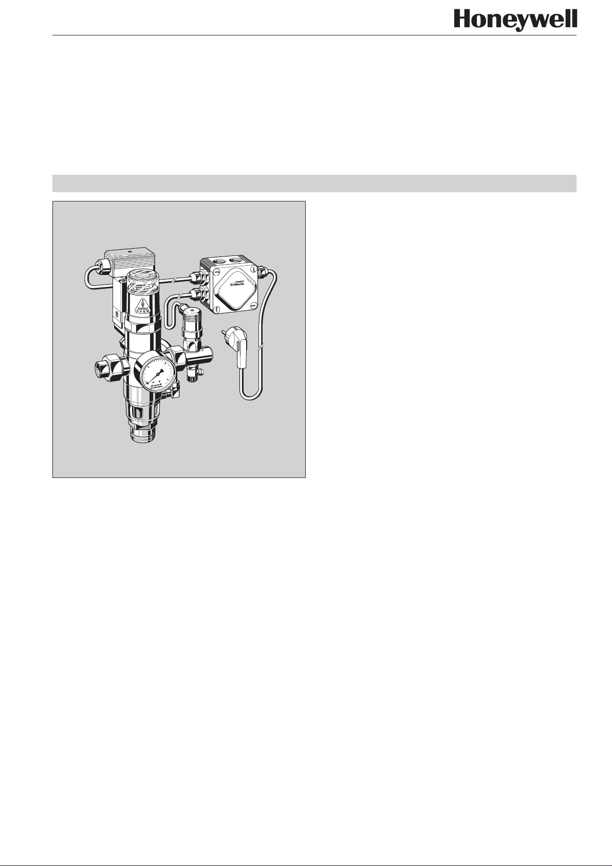
Construction
The refilling unit consists of:
● Threaded drinking water and system connections
● Changeover valve
● R 295 SA -
1
/2" backflow preventer
● Cut-in/cut-out pressure switch
● Electrical connector strip
● Time relay
● Discharge tundish
● Inlet pressure gauge
● Drain valve
● Cable wiring centre
● One meter electrical connection cable
NA 225-A
Automatic refilling unit
for heating and cooling systems
Product specification sheet
Purpose
The NA 225 - A refilling unit with DVGW tested backflow
preventer enables permanent connection of closed heating and
cooling systems to the drinking water network.
It combines a backflow preventer and non-return valve in one
appliance. The refilling unit maintains system pressure between
pre-determined upper and lower limits in closed heating and
cooling circuits. It prevents backflow, back syphonage or back
pressures of heating or cooling water into the drinking water
network and enables limitation of the refilling period. In addition,
it prevents generation of steam in a system caused by pressure
loss.
Special Features
● DVGW approved
● Pressure switch
● Drain valve for when cut-in and cut-out pressures are
to be changed
● Electronic time relay for limitation of the filling period
● Inlet pressure gauge
● Standardised discharge connection
Range of Application
The following operating conditions apply for the
downstream system:
System pressure Maximum 4.0 bar
Water temperature
at the refilling unit Maximum 40°C
Technical Data
Refilling Flow rate 110 litres/h at ∆p = 2 bar
Cut-in pressure 2.5 bar (set during manufacture)
Cut-out pressure 2,8 bar
Switching pressure
differential 0,3 bar
Inlet water pressure Minimum 3.0 bar, maximum 4.0 bar**
Electrical supply 230 V~ 50/60 Hz
Electrical loadv 30 W
** A pressure reducing valve must be fitted for inlet pr essur es above 4.0 bar
Subject to change 03/99
233
Page 2
Automatic refilling unit NA 225-A
H
Nachfüllstation
Typ: FA225
CE
230V •
50 / 60 HZ
20W IP65
Method of Operation
If the system pressure falls below the set limit, for example
because of leakage losses, then the changeover valve is
opened by an electrical impulse from the pressure switch and
thereby opens the hydraulic supply to the backflow preventer.
The inlet pressure brings the backflow preventer to the flow
position and the system is refilled up to the pre-set upper
pressure limit. The duration of fill is controlled by the time relay.
Once the upper fill pressure has been reached, the pressure
switch cuts out, the changeover valve closes and the backflow
preventer goes to the cutoff position. The time relay goes to the
outlet position.
If the inlet pressure during the filling operation falls to the
backflow preventer set pressure (2 bar), the backflow preventer
automatically goes to the shutoff position (open to atmosphere).
The shutoff position of the backflow preventer is indicated in
the viewing window (green visible = shutoff position).
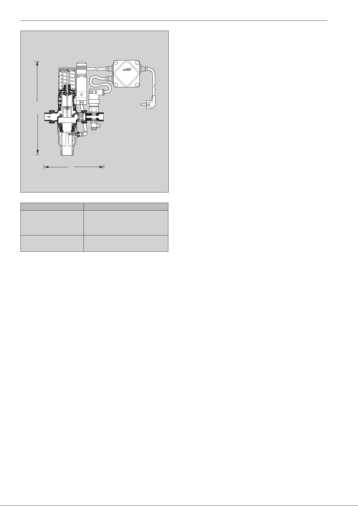
B
Weight Approx. kg 2,9
Dimensions (mm)
H 285
B 188
T65
Test No. for R 295 SA
backflow preventer DIN/DVGW 569 E
Versions
A = Normalausführung
Ordering Number
NA 225 - A
234
Braukmann Water Control . Honeywell AG
Subject to change 03/99
Page 3

Installation example (Heating system)
5
0
Automatic refilling unit NA 225-A
10
15
16
Installation Guidelines
● Install appliance in correct flow direction
● Fit isolating valves
❍ With isolating valves,
is possible maintenance and service without removal from the
pipework
● Ensure good access
❍ Simplifies maintenance and inspection
● A pressure reducing valve must be fitted for inlet pressures
greater than 4.0 bar
Flow Diagram (water)
Refilling
Typical Applications
The NA 225-A refilling unit enables a permanent connection of
closed heating or cooling systems to the drinking water
network.
Refilling units can be fitted:
● If the system pressure must be maintained
● If generation of steam caused by system pressure loss
must be prevented
● For limitation of the refilling duration
Flow rate (litres/h)
Subject to change 03/99 Braukmann Water Control . Honeywell AG
235
Page 4

Automatic refilling unit NA 225-A
Spare Parts - NA 225 - A refilling unit
1998 and onwards
Description Part Number
⑩
②
⑤
R
A
P
④
⑤
① Pressure switch 5670500
② Changeover valve 0903417
③ Pressure gauge M 07 K - A16
④ Valve insert R 295 SAA-1D
⑤ Seal 0901015
⑤
1
⑥ Hexagonal blanking plug S 06 M -
⑤
①
⑤
⑦
⑥
- With seal (Packs of 5)
⑦ Seal ring 5017500
⑧ Non-return valve RV 282 E -
⑨ Discharge tundish 0901340
/4
3
/4 A
⑦
10
5
15
16
0
⑤
⑧
③
⑩ Time relay 2595700
⑨
⑤
⑤
⑨
Subject to change 03/99
Braukmann Water Control . Honeywell AG
P.O. Box 1347
D - 74819 Mosbach-Germany
Phone:
(49) 62 61/ 06261/810 · Fax: 06261/813 09 http://europe.hbc.honeywell.com
236
 Loading...