

Page 1

N86XX Decoded Engine
User’s Guide
™
Page 2

Disclaimer
Honeywell International Inc. (“HII”) reserves the right to make changes in specifications and other information contained in this document without prior notice,
and the reader should in all cases consult HII to determine whether any such
changes have been made. The information in this publication does not represent a commitment on the part of HII.
HII shall not be liable for technical or editorial errors or omissions contained
herein; nor for incidental or consequential damages resulting from the furnishing, performance, or use of this material.
This document contains proprietary information that is protected by copyright.
All rights are reserved. No part of this document may be photocopied, reproduced, or translated into another language without the prior written consent of
HII.
© 2012 Honeywell International Inc. All rights reserved.
Other product names or marks mentioned in this document may be trademarks
or registered trademarks of other companies and are the property of their
respective owners.
Web Address:
Microsoft® Windows®, Windows NT®, Windows 2000, Windows ME, Windows
XP, and the Windows logo are trademarks or registered trademarks of Microsoft
Corporation.
The Bluetooth® word mark and logos are owned by Bluetooth SIG, Inc.
Other product names or marks mentioned in this document may be trademarks
or registered trademarks of other companies and are the property of their
respective owners.
www.honeywellaidc.com
Page 3

Product Agency Compliance
Note: It is the OEM manufacturer’s responsibility to comply with
applicable regulation(s) in regard to standards for specific
equipment combinations.
Honeywell shall not be liable for use of our product with
equipment (i.e., power supplies, personal computers, etc.) that is
not CE marked and does not comply with the Low Voltage
Directive.
For CE-related inquiries, please contact:
Honeywell Imaging & Mobility Europe BV
Nijverheidsweg 9-13
5627 BT Eindhoven
The Netherlands
CB Scheme
IEC 60950-1 Second Edition
UL/C-UL (Recognized component)
UL 60950-1 Second Edition
CSA C22.2 No. 60950-1-07, 2nd Edition
LED Safety Statement
LEDs have been tested and classified as “EXEMPT RISK
GROUP” to the standard IEC 62471:2006.
ESD Precautions
The engine is shipped in ESD safe packaging. Use care when
handling the scan engine outside its packaging. Be sure
grounding wrist straps and properly grounded work areas are
used.
Page 4

Dust and Dirt
The engine must be sufficiently enclosed to prevent dust
particles from gathering on the imager and lens. When stocking
the unit, keep it in its protective packaging. Dust and other
external contaminants will eventually degrade unit performance.
RoHS
The engine is in compliance with Directive 2002/95/EC,
Restriction of the Use of Certain Hazardous Substances in
Electrical and Electronic Equipment (RoHS), dated January,
2003.
D-Mark Statement
Certified to EN 60950-1 Information Technology Equipment
product safety, as a component assembly.
Page 5

Table of Contents
Chapter 1 - Getting Started
Introduction ................................................................. 1-1
About This Manual ......................................................1-1
Unpacking Your Device............................................... 1-1
OEM Engine Models ...................................................1-2
Connecting the Development Engine to the PC.......... 1-3
Connecting with USB ............................................ 1-3
Connecting with RS232 Serial Port....................... 1-5
Menu Bar Code Security Settings ............................... 1-6
Setting Custom Defaults ............................................. 1-6
Resetting the Custom Defaults ................................... 1-6
Resetting the Factory Defaults.................................... 1-7
Chapter 2 - Programming the Interface
Introduction ................................................................. 2-1
Programming the Interface - Plug and Play ................ 2-1
RS232 Serial Port.................................................. 2-1
USB PC................................................................. 2-1
USB COM Port Emulation..................................... 2-1
Verifone
Gilbarco
Keyboard Country Layout ........................................... 2-4
Keyboard Style.......................................................... 2-10
Keyboard Conversion................................................ 2-12
Control Character Output .......................................... 2-12
Keyboard Modifiers ................................................... 2-13
RS232 Baud Rate ..................................................... 2-15
RS232 Word Length: Data Bits, Stop Bits, and
Parity ......................................................................... 2-16
RS232 Receiver Time-Out ........................................ 2-17
RS232 Handshaking ................................................. 2-17
RS232 Timeout ................................................... 2-18
XON/XOFF.......................................................... 2-18
ACK/NAK............................................................. 2-18
®
Ruby Terminal Default Settings ............ 2-2
®
Terminal Default Settings ..................... 2-3
i
Page 6

Chapter 3 - Input/Output Settings
Power Up Beeper ........................................................3-1
Beep on BEL Character...............................................3-1
Trigger Click.................................................................3-2
Good Read and Error Indicators..................................3-2
Beeper – Good Read.............................................3-2
Beeper Volume – Good Read................................ 3-3
Beeper Pitch – Good Read....................................3-3
Beeper Pitch – Error ..............................................3-4
Beeper Duration – Good Read ..............................3-4
LED – Good Read .................................................3-4
Number of Beeps – Good Read ............................3-5
Number of Beeps – Error.......................................3-5
Good Read Delay ..................................................3-6
User-Specified Good Read Delay.......................... 3-6
Manual Trigger Modes.................................................3-6
Serial Trigger Mode .....................................................3-7
Read Time-Out ......................................................3-7
Image Snap and Ship ..................................................3-8
Reread Delay...............................................................3-8
User-Specified Reread Delay ......................................3-9
Illumination Lights........................................................3-9
Centering .....................................................................3-9
Preferred Symbology.................................................3-11
High Priority Symbology ......................................3-11
Low Priority Symbology .......................................3-12
Preferred Symbology Time-out............................3-12
Preferred Symbology Default............................... 3-12
Output Sequence Overview.......................................3-13
Require Output Sequence ...................................3-13
Output Sequence Editor ......................................3-13
To Add an Output Sequence ...............................3-13
Other Programming Selections............................ 3-14
Output Sequence Editor ......................................3-15
Partial Sequence .................................................3-15
Require Output Sequence ...................................3-16
ii
Page 7

Multiple Symbols ....................................................... 3-16
No Read .................................................................... 3-17
Video Reverse........................................................... 3-18
Chapter 4 - Data Editing
Prefix/Suffix Overview ................................................. 4-1
To Add a Prefix or Suffix: ...................................... 4-1
To Clear One or All Prefixes or Suffixes................ 4-2
To Add a Carriage Return Suffix to All
Symbologies.......................................................... 4-3
Prefix Selections ......................................................... 4-3
Suffix Selections.......................................................... 4-4
Function Code Transmit.............................................. 4-4
Intercharacter, Interfunction, and Intermessage
Delays ......................................................................... 4-4
Intercharacter Delay.............................................. 4-5
User Specified Intercharacter Delay...................... 4-5
Interfunction Delay ................................................ 4-6
Intermessage Delay .............................................. 4-6
Chapter 5 - Data Formatting
Data Format Editor Introduction .................................. 5-1
To Add a Data Format................................................. 5-1
Other Programming Selections ............................. 5-3
Terminal ID Table........................................................ 5-4
Data Format Editor Commands .................................. 5-4
Move Commands .................................................. 5-5
Search Commands................................................ 5-6
Miscellaneous Commands .................................... 5-7
Data Formatter ............................................................ 5-8
Data Format Non-Match Error Tone...................... 5-9
Primary/Alternate Data Formats................................ 5-10
Single Scan Data Format Change....................... 5-10
iii
Page 8

Chapter 6 - Symbologies
All Symbologies ...........................................................6-2
Message Length Description .......................................6-2
Codabar.......................................................................6-3
Codabar Concatenation.........................................6-4
Code 39 .......................................................................6-6
Code 32 Pharmaceutical (PARAF) ........................ 6-8
Full ASCII............................................................... 6-9
Code 39 Code Page ..............................................6-9
Interleaved 2 of 5.......................................................6-10
NEC 2 of 5 .................................................................6-12
Code 93 .....................................................................6-14
Code 93 Code Page ............................................6-14
Straight 2 of 5 Industrial (three-bar start/stop)...........6-15
Straight 2 of 5 IATA (two-bar start/stop) ....................6-16
Matrix 2 of 5...............................................................6-17
Code 11 .....................................................................6-18
Code 128 ...................................................................6-19
ISBT 128 Concatenation...................................... 6-19
Code 128 Code Page ..........................................6-21
GS1-128 ....................................................................6-22
Telepen......................................................................6-23
UPC-A........................................................................6-24
UPC-A/EAN-13
with Extended Coupon Code...................................6-26
UPC-E0......................................................................6-27
UPC-E1......................................................................6-30
EAN/JAN-13 ..............................................................6-30
ISBN Translate ....................................................6-32
EAN/JAN-8 ................................................................6-33
MSI ............................................................................6-35
GS1 DataBar Omnidirectional ...................................6-37
GS1 DataBar Limited.................................................6-37
GS1 DataBar Expanded ............................................6-38
Trioptic Code .............................................................6-39
Codablock A ..............................................................6-39
iv
Page 9

Codablock F .............................................................. 6-41
PDF417 ..................................................................... 6-42
MicroPDF417 ............................................................ 6-43
GS1 Composite Codes ............................................. 6-44
UPC/EAN Version ............................................... 6-44
GS1 Emulation .......................................................... 6-45
TCIF Linked Code 39 (TLC39).................................. 6-46
QR Code ................................................................... 6-46
Data Matrix................................................................ 6-48
Data Matrix Code Page....................................... 6-48
MaxiCode .................................................................. 6-49
Aztec Code................................................................ 6-50
Aztec Code Page ................................................ 6-50
Chinese Sensible (Han Xin) Code ............................ 6-51
Postal Codes - 2D ..................................................... 6-52
Single 2D Postal Codes: ..................................... 6-52
Combination 2D Postal Codes: ........................... 6-53
Postal Codes - Linear................................................ 6-55
China Post (Hong Kong 2 of 5) ........................... 6-55
Korea Post........................................................... 6-57
Chapter 7 - Imaging Commands
Single-Use Basis......................................................... 7-1
Command Syntax........................................................ 7-1
Image Snap - IMGSNP ............................................... 7-2
IMGSNP Modifiers................................................. 7-2
Image Ship - IMGSHP................................................. 7-5
IMGSHP Modifiers................................................. 7-5
Intelligent Signature Capture - IMGBOX ................... 7-14
Signature Capture Optimize................................ 7-14
IMGBOX Modifiers .............................................. 7-15
Chapter 8 - Interface Keys
Keyboard Function Relationships ............................... 8-1
Supported Interface Keys............................................ 8-2
v
Page 10

Chapter 9 - Utilities
To Add a Test Code I.D. Prefix to All
Symbologies..............................................................9-1
Show Decoder Revision ..............................................9-1
Show Scan Driver Revision .........................................9-1
Show Software Revision..............................................9-1
Show Data Format.......................................................9-2
Test Menu....................................................................9-2
TotalFreedom ..............................................................9-2
Application Plug-Ins (Apps) .........................................9-3
EZConfig Introduction..................................................9-3
Installing EZConfig from the Web .......................... 9-4
Chapter 10 - Serial Programming Commands
Conventions...............................................................10-1
Menu Command Syntax ............................................10-1
Query Commands......................................................10-2
Responses...........................................................10-2
Trigger Commands....................................................10-4
Resetting the Custom Defaults..................................10-4
Menu Commands ......................................................10-5
Chapter 11 - Maintenance
Repairs ......................................................................11-1
Inspecting Cords and Connectors .......................11-1
Troubleshooting.........................................................11-1
Chapter 12 - Customer Support
Technical Assistance.................................................12-1
Appendix A - Reference Charts
Symbology Chart ........................................................ A-1
ASCII Conversion Chart (Code Page 1252)............... A-4
Code Page Mapping of Printed Bar Codes................. A-6
vi
Page 11

1
Getting Started
Introduction
The N86XX engine is designed for integration into a wide range of OEM
devices. The engine’s compact mechanical design can drop into many existing
applications, allowing OEMs and third-party manufacturers to integrate the benefits of image-based scanning into a variety of devices, including hand held
computers (medical instrumentation, kiosks, diagnostic equipment, and robotics.
Three different decoding configurations provide OEMs the flexibility required to
address various application-specific needs. The N8610/8613, with linear
decoding, delivers laser-like reading on linear codes. The N8680/8683 unit
decodes linear as well as 2D and postal codes. In addition to linear, 2D, and
postal codes, the N8690/8693 unit includes the OCR feature. For software
updates and additional information, visit the Honeywell website at
www.honeywellaidc.com.
About This Manual
This User’s Guide provides demonstration, installation, and programming
instructions for the N86XX engine. Dimensions, warranty, and customer support information are also included.
Honeywell’s bar code scanners are factory programmed for the most common
terminal and communications settings. If you need to change these settings,
programming is accomplished by scanning the bar codes in this guide.
An asterisk (*) next to an option indicates the default setting.
Unpacking Your Device
After you open the shipping carton containing the OEM engine(s), take the following steps:
• Check for damage during shipment. Report damage immediately to the
carrier who delivered the carton.
• Make sure the items in the carton match your order.
• Save the shipping container for later storage or shipping.
1 - 1
Page 12

OEM Engine Models
There are three models of the OEM engine, which may be used with the interfaces described in this manual. Refer to the chart below to determine the mod-
els that can be used with your interface.
Models Interface Decoding Capability
N868XX-XXX-XX2 TTL Level 232 Linear, 2D, postal
N868XX-XXX-XX3 Full-Speed USB Linear, 2D, postal
N868XX-XXX-XX5 High-Speed USB Linear, 2D, postal
N869XX-XXX-XX2 TTL Level 232 Linear, 2D, postal,
N869XX-XXX-XX3 Full-Speed USB Linear, 2D, postal,
N869XX-XXX-XX5 High-Speed USB Linear, 2D, postal,
OCR
OCR
OCR
1 - 2
Page 13
Connecting the Development Engine to the PC
The development OEM engine can connect to a PC for evaluation.
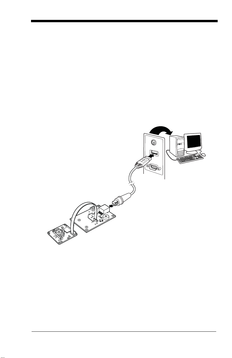
Connecting with USB
Note: If using the N86XXX-XXX-XX5 engine with USB Micro-B, do not supply
power through the flex connector. Doing so may damage the host or
engine. The N86XXX-XXX-XX5 engine will only communicate USB
through the Micro-B connector. The N86XXX-XXX-XX3 engine will only
communicate USB through the 10 pin modular connector.
1. Turn off power to the terminal/computer.
2. If using full-speed USB, connect the USB interface cable to the
interface board and to the matching USB port on the computer.
1 - 3
Page 14

2a. If using hi-speed USB, connect the USB interface cable to the side of
Full-Speed USB
High-Speed USB
the engine and to the USB port on the computer.
Note: For additional USB programming and technical information, refer to
Honeywell’s “USB Application Note,” available at
www.honeywellaidc.com.
3. When connecting the engine using full-speed or high-speed USB, all
communication parameters between the engine and terminal must
match for correct data transfer using USB protocol. Scan the
appropriate USB interface bar code below.
4. Verify the engine operation by scanning a bar code from the Sample
Symbols in the back of this manual. The engine beeps once when a
bar code is successfully decoded.
1 - 4
Page 15
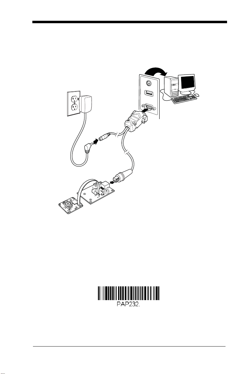
Connecting with RS232 Serial Port
RS-232 Interface
1. If using an RS-232 connection, connect the serial interface cable to
the interface board and to the matching port on the back of the computer.
2. Connect the power supply connector to the serial interface cable. Plug
in the power supply.
3. Turn the terminal/computer power back on. The engine beeps.
4. If connecting the engine using an RS-232 interface, all communication
parameters between the engine and terminal must match for correct
data transfer through the serial port using RS-232 protocol. Scan the
RS-232 interface bar code below. This programs the engine for an
RS-232 interface at 115,200 baud, parity–none, 8 data bits, 1 stop bit,
and adds a suffix of a CR LF.
1 - 5
Page 16

5. Verify the engine operation by scanning a bar code from the Sample
Save Custom Defaults
Set Custom Defaults
Symbols in the back of this manual. The engine beeps once when a
bar code is successfully decoded.
To connect an engine to your host system, refer to the N86XX Integration
Manual.
Menu Bar Code Security Settings
Honeywell scanners are programmed by scanning menu bar codes or by sending serial commands to the engine. If you want to restrict the ability to scan
menu codes, you can use the Menu Bar Code Security settings. Contact the
nearest technical support office (see Technical Assistance on page 12-1) for
further information.
Setting Custom Defaults
You have the ability to create a set of menu commands as your own, custom
defaults. To do so, scan the Set Custom Defaults bar code below before scanning the menu commands for your custom defaults. If a menu command
requires scanning numeric codes from the back cover, then a Save code, that
entire sequence will be saved to your custom defaults. When you have entered
all the commands you want to save for your custom defaults, scan the Save
Custom Defaults bar code.
You may have a series of custom settings and want to correct a single setting.
To do so, just scan the new setting to overwrite the old one. For example, if you
had previously saved the setting for Beeper Volume at Low to your custom
defaults, and decide you want the beeper volume set to High, just scan the Set
Custom Defaults bar code, then scan the Beeper Volume High menu code,
and then Save Custom Defaults. The rest of the custom defaults will remain,
but the beeper volume setting will be updated.
Resetting the Custom Defaults
If you want the custom default settings restored to your engine, scan the Activate Custom Defaults bar code below. This is the recommended default bar
code for most users. It resets the engine to the custom default settings. If there
1 - 6
Page 17

are no custom defaults, it will reset the engine to the factory default settings.
Activate Custom Defaults
!
Remove Custom Defaults
Activate Defaults
Any settings that have not been specified through the custom defaults will be
defaulted to the factory default settings.
Resetting the Factory Defaults
This selection erases all your settings and resets the engine to the original factory defaults. It also disables all plugins
If you aren’t sure what programming options are in your engine, or you’ve
changed some options and want to restore the engine to factory default settings, first scan the Remove Custom Defaults bar code, then scan Activate
Defaults. This resets the engine to the factory default settings.
The Menu Commands, beginning on page 10-5 list the factory default settings
for each of the commands (indicated by an asterisk (*) on the programming
pages).
.
1 - 7
Page 18

1 - 8
Page 19

2
RS232 Interface
U
S
B
K
e
y
b
o
a
r
d
(
P
C
)
Programming the Interface
Introduction
This chapter describes how to program your system for the desired interface.
Programming the Interface - Plug and Play
Plug and Play bar codes provide instant set up for commonly used interfaces.
Note: After you scan one of the codes, power cycle the host terminal to have
the interface in effect.
RS232 Serial Port
The RS232 Interface bar code is used when connecting to the serial port
of a PC or terminal. The following RS232 Interface bar code also programs a carriage return (CR) and a line feed (LF) suffix, baud rate, and
data format as indicated below. It also changes the trigger mode to man-
ual.
Option Setting
Baud Rate 115,200 bps
Data Format 8 data bits, no parity bit, 1 stop bit
USB PC
Scan the following code to program the engine for USB PC Keyboard.
Scanning this code also adds a CR and LF.
USB COM Port Emulation
Scan the following code to program the engine to emulate a regular
RS232-based COM Port. If you are using a Microsoft® Windows® PC, you
will need to download a driver from the Honeywell website
2 - 1
Page 20
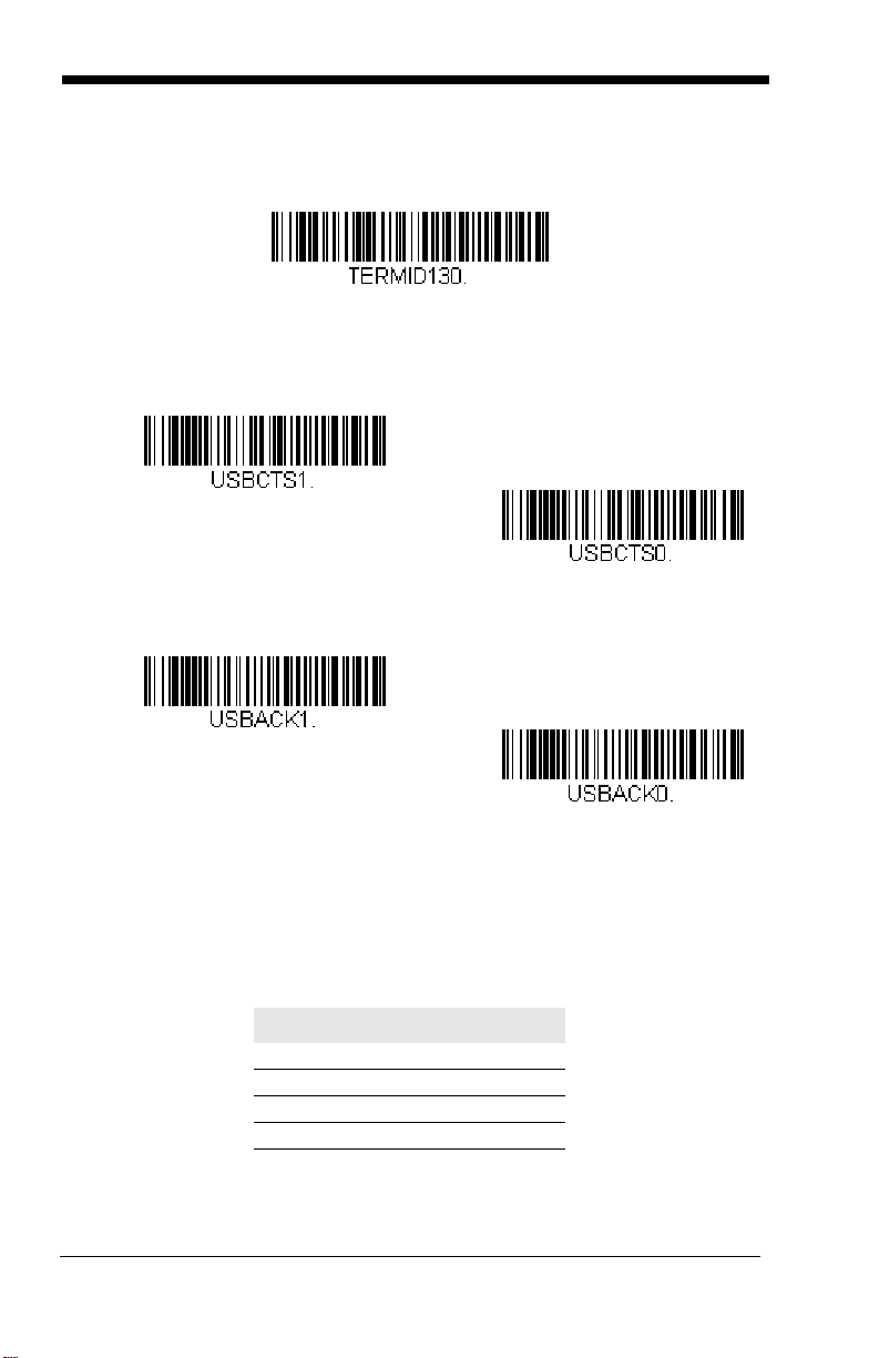
(www.honeywellaidc.com). The driver will use the next available COM Port
USB COM Port Emulation
CTS/RTS Emulation On
* CTS/RTS Emulation Off
ACK/NAK Mode On
* ACK/NAK Mode Off
number. Apple® Macintosh computers recognize the engine as a USB
CDC class device and automatically uses a class driver.
Note: No extra configuration (e.g., baud rate) is necessary.
CTS/RTS Emulation
ACK/NAK Mode
Verifone® Ruby Terminal Default Settings
Scan the following Plug and Play code to program the scanner for a Verifone Ruby terminal. This bar code sets the baud rate to 1200 bps and the
data format to 8 data bits, no parity bit, 1 stop bit. It also adds a line feed
(LF) suffix and programs the following prefixes for each symbology:
Symbology Prefix
UPC-A A
UPC-E A
EAN-8 FF
EAN-13 F
2 - 2
Page 21

Gilbarco® Terminal Default Settings
Verifone Ruby Settings
Gilbarco Settings
Scan the following Plug and Play code to program the scanner for a Gilbarco terminal. This bar code sets the baud rate to 2400 bps and the data
format to 7 data bits, even parity, 2 stop bits. It also adds a carriage return
(CR) suffix and programs the following prefixes for each symbology:
Symbology Prefix
UPC-A A
UPC-E E0
EAN-8 FF
EAN-13 F
2 - 3
Page 22
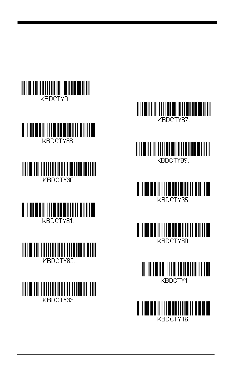
Keyboard Country Layout
* United States
United States (Dvorak left)
United States (International)
Albania
Azeri (Cyrillic)
Azeri (Latin)
Belarus
Belgium
United States (Dvorak)
United States (Dvorak right)
Bosnia
Brazil
Scan the appropriate country code below to program the keyboard layout for
your country or language. As a general rule, the following characters are supported, but need special care for countries other than the United States:
@ | $ # { } [ ] = / ‘ \ < > ~
2 - 4
Page 23
Keyboard Country (continued)
Bulgaria (Latin)
Canada (French)
Canada (Multilingual)
Croatia
Czech
Czech (Programmers)
Czech (QWERTY)
Czech (QWERTZ)
Bulgaria (Cyrillic)
Canada (French legacy)
Brazil (MS)
Denmark
Dutch (Netherlands)
2 - 5
Page 24
Keyboard Country (continued)
Finland
Gaelic
Germany
Greek
Greek (220 Latin)
Greek (220)
Greek (319 Latin)
Greek (319)
Faeroese
France
Estonia
Greek (Latin)
Greek (MS)
2 - 6
Page 25
Keyboard Country (continued)
Italian (142)
Hungarian (101 key)
Iceland
Irish
Italy
Japan ASCII
Kazakh
Kyrgyz (Cyrillic)
Hebrew
Hungary
Greek (Polytonic)
Latin America
Latvia
2 - 7
Page 26
Keyboard Country (continued)
Lithuania (IBM)
Malta
Mongolian (Cyrillic)
Norway
Poland
Polish (214)
Polish (Programmers)
Portugal
Lithuania
Macedonia
Latvia (QWERTY)
Romania
Russia
2 - 8
Page 27
Keyboard Country (continued)
SCS
Serbia (Latin)
Slovakia
Slovakia (QWERTY)
Slovakia (QWERTZ)
Slovenia
Spain
Spanish variation
Russian (Typewriter)
Serbia (Cyrillic)
Russian (MS)
Sweden
Switzerland (French)
2 - 9
Page 28
Keyboard Country (continued)
Turkey F
Ukrainian
United Kingdom
United Stated (Dvorak right)
United States (Dvorak left)
United States (Dvorak)
United States (International)
Uzbek (Cyrillic)
Tatar
Turkey Q
Switzerland (German)
Keyboard Style
This programs keyboard styles, such as Caps Lock and Shift Lock. If you have
used Keyboard Conversion settings, they will override any of the following Key-
board Style settings.
2 - 10
Default = Regular.
Page 29
Regular is used when you normally have the Caps Lock key off.
* Regular
Caps Lock
Shift Lock
Automatic Caps Lock
Autocaps via NumLock
Caps Lock
Shift Lock
is used when you normally have the Caps Lock key on.
is used when you normally have the Shift Lock key on (not common
to U.S. keyboards).
Automatic Caps Lock is used if you change the Caps Lock key on and off.
The software tracks and reflects if you have Caps Lock on or off. This selection
can only be used with systems that have an LED that notes the Caps Lock status (AT keyboards).
Autocaps via NumLock
bar code should be scanned in countries (e.g., Germany, France) where the Caps Lock key cannot be used to toggle Caps Lock.
The NumLock option works similarly to the regular Autocaps, but uses the NumLock key to retrieve the current state of the Caps Lock.
2 - 11
Page 30
Emulate External Keyboard should be scanned if you do not have an external
Emulate External Keyboard
* Keyboard Conversion Off
Convert All Characters
to Upper Case
Convert All Characters
to Lower Case
keyboard (IBM AT or equivalent).
Note: After scanning the Emulate External Keyboard bar code, you must power
cycle your computer.
Keyboard Conversion
Alphabetic keyboard characters can be forced to be all upper case or all lowercase. So if you have the following bar code: “abc569GK,” you can make the
output “ABC569GK” by scanning Convert All Characters to Upper Case, or to
“abc569gk” by scanning Convert All Characters to Lower Case.
These settings override Keyboard Style selections.
Note: If your interface is a keyboard wedge, first scan the menu code for
Automatic Caps Lock (page 2-11). Otherwise, your output may not be as
expected.
Default = Keyboard Conversion Off
.
Control Character Output
This selection sends a text string instead of a control character. For example,
when the control character for a carriage return is expected, the output would
display [CR] instead of the ASCII code of 0D. Refer to ASCII Conversion Chart
(Code Page 1252) on page A-4. Only codes 00 through 1F are converted (the
first column of the chart).
Note: Control + ASCII Mode overrides this mode.
2 - 12
Page 31

Default = Off.
Control Character Output On
* Control Character Output Off
Windows Mode Control + ASCII
Mode On
* Control + ASCII Mode Off
DOS Mode Control + ASCII Mode
On
Windows Mode Prefix/Suffix Off
Keyboard Modifiers
This modifies special keyboard features, such as CTRL+ ASCII codes and
Turbo Mode.
Control + ASCII Mode On: The engine sends key combinations for ASCII control characters for values 00-1F. Windows is the preferred mode. All keyboard
country codes are supported. DOS mode is a legacy mode, and it does not
support all keyboard country codes. New users should use the Windows mode.
Refer to Keyboard Function Relationships, page 8-1 for CTRL+ ASCII Values.
Windows Mode Prefix/Suffix Off: The engine sends key combinations for
ASCII control characters for values 00-1F, but it does not transmit any prefix or
suffix information.
Default = Control + ASCII Mode Off.
2 - 13
Page 32

Turbo Mode: The engine sends characters to a terminal faster. If the terminal
Turbo Mode On
* Turbo Mode Off
Numeric Keypad Mode On
* Numeric Keypad Mode Off
Automatic Direct Connect Mode
On
* Automatic Direct Connect
Mode Off
drops characters, do not use Turbo Mode.
Default = Off
Numeric Keypad Mode: Sends numeric characters as if entered from a
numeric keypad.
Default = Off
Automatic Direct Connect Mode: This selection can be used if you have an
IBM AT style terminal and the system is dropping characters.
Default = Off
2 - 14
Page 33

RS232 Baud Rate
300
2400
600
1200
4800
38400
* 9600
19200
115,200
57,600
Baud Rate sends the data from the engine to the terminal at the specified rate.
The host terminal must be set for the same baud rate as the engine.
Default =
9600.
2 - 15
Page 34

RS232 Word Length: Data Bits, Stop Bits,
7 Data, 1 Stop, Parity Even
7 Data, 1 Stop, Parity None
7 Data, 1 Stop, Parity Odd
7 Data, 2 Stop, Parity Even
7 Data, 2 Stop Parity None
* 8 Data, 1 Stop, Parity None
8 Data, 1 Stop, Parity Even
7 Data, 2 Stop, Parity Odd
8 Data, 1 Stop, Parity Odd
and Parity
Data Bits sets the word length at 7 or 8 bits of data per character. If an applica-
tion requires only ASCII Hex characters 0 through 7F decimal (text, digits, and
punctuation), select 7 data bits. For applications that require use of the full
ASCII set, select 8 data bits per character.
Stop Bits sets the stop bits at 1 or 2.
Parity provides a means of checking character bit patterns for validity.
Default = None.
Default = 8.
Default = 1.
2 - 16
Page 35

RS232 Receiver Time-Out
RS232 Receiver Time-Out
Flow Control, No Timeout
* RTS/CTS Off
Two-Direction Flow Control
Flow Control with Timeout
The unit stays awake to receive data until the RS232 Receiver Time-Out
expires. A manual or serial trigger resets the time-out. When an RS232
receiver is sleeping, a character may be sent to wake up the receiver and reset
the time-out. A transaction on the CTS line will also wake up the receiver. The
receiver takes 300 milliseconds to completely come up. Change the RS232
receiver time-out by scanning the bar code below, then scanning digits from the
inside back cover of this manual, then scanning Save. The range is 0 to 300
seconds.
Default = 0 seconds (no time-out - always on).
RS232 Handshaking
RS232 Handshaking allows control of data transmission from the engine using
software commands from the host device. When RTS/CTS is turned Off, no
data flow control is used.
Flow Control, No Timeout: The engine asserts RTS when it has data to send,
and will wait indefinitely for CTS to be asserted by the host.
Two-Direction Flow Control: The engine asserts RTS when it is OK for the
host to transmit. The host asserts CTS when it is OK for the device to transmit.
Flow Control with Timeout: The engine asserts RTS when it has data to send
and waits for a delay (see RS232 Timeout on page 2-18) for CTS to be asserted
by the host. If the delay time expires and CTS is not asserted, the device transmit buffer is cleared and scanning may resume.
Default = RTS/CTS Off.
2 - 17
Page 36

RS232 Timeout
RS232 Timeout
* XON/XOFF Off
XON/XOFF On
When using Flow Control with Timeout, you must program the length of the
delay you want to wait for CTS from the host. Set the length (in milliseconds) for a timeout by scanning the bar code below, then setting the timeout (from 1-5100 milliseconds) by scanning digits from the inside back
cover, then scanning Save.
XON/XOFF
Standard ASCII control characters can be used to tell the engine to start
sending data (XON/XOFF On) or to stop sending data (XON/XOFF Off).
When the host sends the XOFF character (DC3, hex 13) to the engine,
data transmission stops. To resume transmission, the host sends the XON
character (DC1, hex 11). Data transmission continues where it left off
when XOFF was sent.
Default = XON/XOFF Off
.
ACK/NAK
After transmitting data, the engine waits for an ACK character (hex 06) or a
NAK character (hex 15) response from the host. If ACK is received, the
communications cycle is completed and the engine looks for more bar
codes. If NAK is received, the last set of bar code data is retransmitted and
2 - 18
Page 37

the engine waits for ACK/NAK again. Turn on the ACK/NAK protocol by
ACK/NAK On
* ACK/NAK Off
scanning the ACK/NAK On bar code below. To turn off the protocol, scan
ACK/NAK Off.
Default = ACK/NAK Off
.
2 - 19
Page 38

2 - 20
Page 39

3
Power Up Beeper Off -
Scanner
* Power Up Beeper On -
Scanner
*Beep on BEL Off
Beep on BEL On
Input/Output Settings
Power Up Beeper
The engine can be programmed to beep when it’s powered up. If you are using
a cordless system, the base can also be programmed to beep when it is powered up. Scan the Off bar code(s) if you don’t want a power up beep.
Power Up Beeper On - Scanner.
Beep on BEL Character
You may wish to force the engine to beep upon a command sent from the host.
If you scan the Beep on BEL On bar code below, the engine will beep every
time a BEL character is received from the host.
Default = Beep on BEL Off.
Default =
3 - 1
Page 40

Trigger C lick
Trigger Click On
*Trigger Click Off
* Beeper - Good Read On
Beeper - Good Read Off
To hear an audible click every time the trigger is pressed, scan the Trigge r
Click On bar code below. Scan the Tri gger C lick Off code if you don’t wish to
hear the click. (This feature has no effect on serial or automatic triggering.)
Default = Trigger Click Off.
Good Read and Error Indicators
Beeper – Good Read
The beeper may be programmed On or Off in response to a good read.
Turning this option off, only turns off the beeper response to a good read
indication. All error and menu beeps are still audible.
Good Read On.
Default = Beeper -
3 - 2
Page 41

Beeper Volume – Good Read
* High
Medium
Off
Low
Low (1600 Hz)
* Medium (2700 Hz)
High (4200 Hz)
The beeper volume codes modify the volume of the beep the engine emits
on a good read.
Default = High.
Beeper Pitch – Good Read
The beeper pitch codes modify the pitch (frequency) of the beep the engine
emits on a good read.
Default = Medium.
3 - 3
Page 42

Beeper Pitch – Error
* Razz (250 Hz)
Medium (3250 Hz)
High (4200 Hz)
* Normal Beep
Short BeepShort Beep
* LED - Good Read On
LED - Good Read Off
The beeper pitch codes modify the pitch (frequency) of the sound the
engine emits when there is a bad read or error.
Default = Razz.
Beeper Duration – Good Read
The beeper duration codes modify the length of the beep the engine emits
on a good read.
Default = Normal.
LED – Good Read
The LED indicator can be programmed On or Off in response to a good
read.
Default = On.
3 - 4
Page 43

Number of Beeps – Good Read
Number of Good Read Beeps/LED Flashes
Number of Error Beeps/LED Flashes
The number of beeps of a good read can be programmed from 1 - 9. The
same number of beeps will be applied to the beeper and LED in response
to a good read. For example, if you program this option to have five beeps,
there will be five beeps and five LED flashes in response to a good read.
The beeps and LED flashes are in sync with one another. To change the
number of beeps, scan the bar code below and then scan a digit (1-9) bar
code and the Save bar code on the Programming Chart inside the back
cover of this manual.
Default = 1.
Number of Beeps – Error
The number of beeps and LED flashes emitted by the engine for a bad read
or error can be programmed from 1 - 9. For example, if you program this
option to have five error beeps, there will be five error beeps and five LED
flashes in response to an error. To change the number of error beeps, scan
the bar code below and then scan a digit (1-9) bar code and the Save bar
code on the Programming Chart inside the back cover of this manual.
Default = 1.
3 - 5
Page 44

Good Read Delay
* No Delay
Short Delay (500 ms)
Medium Delay (1,000 ms)
Long Delay (1,500 ms)
User-Specified Good Read Delay
This sets the minimum amount of time before the engine can read another
bar code.
Default = 0 ms (No Delay).
User-Specified Good Read Delay
If you want to set your own length for the good read delay, scan the bar
code below, then set the delay (from 0-30,000 milliseconds) by scanning
digits from the inside back cover, then scanning Save.
Manual Trigger Modes
When in manual trigger mode, the scanner scans until a bar code is read, or
until the trigger is released. Two modes are available, Normal and Enhanced.
Normal mode offers good scan speed and the longest working ranges (depth of
field). Enhanced mode will give you the highest possible scan speed but
3 - 6
Page 45

slightly less range than Normal mode. Enhanced mode is best used when you
* Manual Trigger - Normal
Manual Trigger - Enhanced
Read Time-Out
require a very fast scan speed and don’t require a long working range.
= Manual Trigger-Normal.
Default
Serial Trigger Mode
You can activate the scanner either by pressing the trigger, or using a serial trigger command (see Trigger Commands on page 10-4). When in serial mode,
the scanner scans until a bar code has been read or until the deactivate command is sent. The scanner can also be set to turn itself off after a specified time
has elapsed (see Read Time-Out, which follows).
Read Time-Out
Use this selection to set a time-out (in milliseconds) of the scanner’s trigger
when using serial commands to trigger the scanner. Once the scanner has
timed out, you can activate the scanner either by pressing the trigger or
using a serial trigger command. After scanning the Read Time-Out bar
code, set the time-out duration (from 0-300,000 milliseconds) by scanning
digits on the Programming Chart inside the back cover, then scanning
Default = 30,000 ms.
Save.
3 - 7
Page 46

Image Snap and Ship
Image Snap and Ship
Short (500 ms)
* Medium (750 ms)
Long (1000 ms)
Extra Long (2000 ms)
Image Snap and Ship tells the engine to take a picture (rather than read a bar
code) when the trigger is pressed. Once the picture is snapped, it is shipped to
the host system as a jpeg file by default. To revert to bar code reading, you
must change to a different trigger mode (see Manual Trigger Modes beginning
on page 3-6).
Note: You must send a serial command for Manual Trigger Modes (see page
10-13) in order to use menu codes after using Image Snap and Ship.
Reread Delay
This sets the time period before the engine can read the
ond time. Setting a reread delay protects against accidental rereads of the
same bar code. Longer delays are effective in minimizing accidental rereads.
Use shorter delays in applications where repetitive bar code scanning is
required. Reread Delay only works in presentation modes.
same
bar code a sec-
Default = Medium.
3 - 8
Page 47

User-Specified Reread Delay
User-Specified Reread Delay
Lights Off
* Lights On
Bar Code 1
Bar Code 2
If you want to set your own length for the reread delay, scan the bar code below,
then set the delay (from 0-30,000 milliseconds) by scanning digits from the
inside back cover, then scanning Save.
Illumination Lights
If you want the illumination lights on while reading a bar code, scan the Lights
On bar code, below. However, if you want to turn just the lights off, scan the
Lights Off bar code.
Default = Lights On.
Centering
Use Centering to narrow the engine’s field of view to make sure the engine
reads only those bar codes intended by the user. For instance, if multiple codes
are placed closely together, centering will insure that only the desired codes are
read.
In the example below, the gray area is the full engine field of view and the white
area is the centering window. Bar Code 1 will not be read, while Bar Code 2 will
be.
3 - 9
Page 48

The default centering window is a 169x128 pixel area in the center of the
0
100%
100%
Default
Center
40% 60%
40%
60%
Left
Right
Bottom
Top
Left of Centering Window
Top of Centering Window
Right of Centering Window
Bottom of Centering Window
* Centering Off
Centering On
engine’s field of view. The following diagram illustrates the default top, bottom,
left, and right pixel positions, measured from the top and the left side of the
engine’s field of view, which is 844 by 640 pixels.
If a bar code is not within the predefined window, it will not be decoded or output
by the engine. If centering is turned on by scanning Centering On, the engine
only reads codes that intersect the centering window you specify using the Top,
Bottom, Left, or Right bar codes.
Scan Centering On, then scan one of the following bar codes to change the
top, bottom, left, or right of the centering window. Then scan the percent you
want to shift the centering window using digits on the inside back cover of this
manual. Scan Save.
Default Centering = 40% for Top and Left, 60% for Bot-
tom and Right.
3 - 10
Page 49

Preferred Symbology
* Preferred Symbology Off
Preferred Symbology On
High Priority Symbology
The engine can be programmed to specify one symbology as a higher priority
over other symbologies in situations where both bar code symbologies appear
on the same label, but the lower priority symbology cannot be disabled.
For example, you may be using the engine in a retail setting to read U.P.C. symbols, but have occasional need to read a code on a drivers license. Since some
licenses have a Code 39 symbol as well as the PDF417 symbol, you can use
Preferred Symbology to specify that the PDF417 symbol be read instead of the
Code 39.
Preferred Symbology classifies each symbology as high priority, low priority,
or as an unspecified type. When a low priority symbology is presented, the
engine ignores it for a set period of time (see Preferred Symbology Time-out on
page 3-12) while it searches for the high priority symbology. If a high priority
symbology is located during this period, then that data is read immediately.
If the time-out period expires before a high priority symbology is read, the
engine will read any bar code in its view (low priority or unspecified). If there is
no bar code in the engine’s view after the time-out period expires, then no data
is reported.
Scan a bar code below to enable or disable Preferred Symbology.
Preferred Symbology Off.
Default =
High Priority Symbology
To specify the high priority symbology, scan the High Priority Symbology
bar code below. On the Symbology Chart on page A-1, find the symbology
you want to set as high priority. Locate the Hex value for that symbology
and scan the 2 digit hex value from the Programming Chart (inside back
cover). Scan Save to save your selection.
Default = None
3 - 11
Page 50

Low Priority Symbology
Low Priority Symbology
Preferred Symbology Time-out
Preferred Symbology Default
To specify the low priority symbology, scan the Low Priority Symbology bar
code below. On the Symbology Chart on page A-1, find the symbology you
want to set as low priority. Locate the Hex value for that symbology and
scan the 2 digit hex value from the Programming Chart (inside back cover).
If you want to set additional low priority symbologies, scan FF, then scan
the 2 digit hex value from the Programming Chart for the next symbology.
You can program up to 5 low priority symbologies. Scan Save to save your
selection.
Default = None
Preferred Symbology Time-out
Once you have enabled Preferred Symbology and entered the high and low
priority symbologies, you must set the time-out period. This is the period of
time the engine will search for a high priority bar code after a low priority
bar code has been encountered. Scan the bar code below, then set the
delay (from 1-3,000 milliseconds) by scanning digits from the inside back
cover, then scanning Save.
Default = 500 ms.
Preferred Symbology Default
Scan the bar code below to set all Preferred Symbology entries to their
default values.
3 - 12
Page 51

Output Sequence Overview
Require Output Sequence
When turned off, the bar code data will be output to the host as the engine
decodes it. When turned on, all output data must conform to an edited
sequence or the engine will not transmit the output data to the host device.
Note: This selection is unavailable when the Multiple Symbols Selection is
turned on.
Output Sequence Editor
This programming selection allows you to program the engine to output
data (when scanning more than one symbol) in whatever order your application requires, regardless of the order in which the bar codes are
scanned. Reading the
the Universal values, shown below. These are the defaults. Be certain
you want to delete or clear all formats before you read the
Sequence
Note: You must hold the trigger while reading each bar code in a sequence.
Note: To make Output Sequence Editor selections, you’ll need to know the
symbol.
code I.D., code length, and character match(es) your application
requires. Use the Alphanumeric symbols (inside back cover) to read
these options.
To Add an Output Sequence
1. Scan the
Sequence, page 3-16).
Enter Sequence
Default Sequence
symbol (see Require Output
symbol programs the engine to
Default
2. Code I.D.
On the Symbology Chart on page A-1, find the symbology to which you
want to apply the output sequence format. Locate the Hex value for that
symbology and scan the 2 digit hex value from the Programming Chart
(inside back cover).
3. Length
Specify what length (up to 9999 characters) of data output will be
acceptable for this symbology. Scan the four digit data length from the
Programming Chart. (Note: 50 characters is entered as 0050. 9999 is
a universal number, indicating all lengths.) When calculating the length,
you must count any programmed prefixes, suffixes, or formatted
characters as part of the length (unless using 9999).
4. Character Match Sequences
On the Code Page Mapping of Printed Bar Codes, page A-6, find the
Hex value that represents the character(s) you want to match. Use the
Programming Chart to read the alphanumeric combination that
represents the ASCII characters. (99 is the Universal number,
indicating all characters.)
3 - 13
Page 52

5. End Output Sequence Editor
A - Code 39
B - Code 128
C - Code 93
F F
Scan
Save
to enter an Output Sequence for an additional symbology, or
to save your entries.
Other Programming Selections
•
Discard
This exits without saving any Output Sequence changes.
Output Sequence Example
In this example, you are scanning Code 93, Code 128, and Code 39 bar
codes, but you want the engine to output Code 39 1st, Code 128 2nd, and
Code 93 3rd, as shown below.
Note: Code 93 must be enabled to use this example.
You would set up the sequence editor with the following command line:
SEQBLK62999941FF6A999942FF69999943FF
The breakdown of the command line is shown below:
SEQBLKsequence editor start command
62 code identifier for Code 39
9999 code length that must match for Code 39, 9999 = all lengths
41 start character match for Code 39, 41h = “A”
FF termination string for first code
6A code identifier for Code 128
9999 code length that must match for Code 128, 9999 = all lengths
42 start character match for Code 128, 42h = “B”
FF termination string for second code
69 code identifier for Code 93
9999 code length that must match for Code 93, 9999 = all lengths
43 start character match for Code 93, 43h = “C”
3 - 14
Page 53

FF termination string for third code
Default Sequence
Enter Sequence
To program the previous example using specific lengths, you would have to
count any programmed prefixes, suffixes, or formatted characters as part of
the length. If you use the example on page 3-14, but assume a <CR> suffix
and specific code lengths, you would use the following command line:
SEQBLK62001241FF6A001342FF69001243FF
The breakdown of the command line is shown below:
SEQBLKsequence editor start command
62 code identifier for Code 39
0012 A - Code 39 sample length (11) plus CR suffix (1) = 12
41 start character match for Code 39, 41h = “A”
FF termination string for first code
6A code identifier for Code 128
0013 B - Code 128 sample length (12) plus CR suffix (1) = 13
42 start character match for Code 128, 42h = “B”
FF termination string for second code
69 code identifier for Code 93
0012 C - Code 93 sample length (11) plus CR suffix (1) = 12
43 start character match for Code 93, 43h = “C”
FF termination string for third code
Output Sequence Editor
Partial Sequence
If an output sequence operation is terminated before all your output
sequence criteria are met, the bar code data acquired to that point is a
“partial sequence.”
3 - 15
Page 54

Scan Discard Partial Sequence to discard partial sequences when the
Transmit Partial Sequence
* Discard Partial Sequence
Required
On/Not Required
*Off
output sequence operation is terminated before completion. Scan Transmit Partial Sequence to transmit partial sequences. (Any fields in the
sequence where no data match occurred will be skipped in the output.)
Require Output Sequence
When an output sequence is Required, all output data must conform to an
edited sequence or the engine will not transmit the output data to the host
device. When it’s On/Not Required, the engine will attempt to get the output data to conform to an edited sequence but, if it cannot, the engine
transmits all output data to the host device as is.
Off
When the output sequence is
the engine decodes it.
Default = Off.
Note: This selection is unavailable when the Multiple Symbols Selection is
turned on.
, the bar code data is output to the host as
Multiple Symbols
When this programming selection is turned On, it allows you to read multiple
symbols with a single pull of the trigger. If you press and hold the trigger, aiming at a series of symbols, it reads unique symbols once, beeping (if turned on)
3 - 16
Page 55

for each read. The engine attempts to find and decode new symbols as long as
On
* Off
On
* Off
the trigger is pulled. When this programming selection is turned Off, the engine
will only read the symbol closest to the center of the image.
Default = Off.
No Read
With No Read turned On, the engine notifies you if a code cannot be read. If
using an EZConfig Tool Scan Data Window (see page 9-3), an “NR” appears
when a code cannot be read. If No Read is turned Off, the “NR” will not appear.
Default = Off.
If you want a different notation than “NR,” for example, “Error,” or “Bad Code,”
you can edit the output message (see Data Formatting beginning on page 5-1).
The hex code for the No Read symbol is 9C.
3 - 17
Page 56

Video Reverse
Video Reverse Only
* Video Reverse Off
VIDREV0.
Video Reverse and Standard Bar
Codes
Video Reverse is used to allow the engine to read bar codes that are inverted.
The Video Reverse Off bar code below is an example of this type of bar code.
Scan Video Reverse Only to read
Reverse and Standard Bar Codes to read both types of codes.
Note: After scanning Video Reverse Only, menu bar codes cannot be read.
You must scan Video Reverse Off or Video Reverse and Standard Bar
Codes in order to read menu bar codes.
Note: Images downloaded from the unit are not reversed. This is a setting for
decoding only.
only
inverted bar codes. Scan Video
3 - 18
Page 57

4
Data Editing
Prefix/Suffix Overview
When a bar code is scanned, additional information is sent to the host computer
along with the bar code data. This group of bar code data and additional,
user-defined data is called a “message string.” The selections in this section
are used to build the user-defined data into the message string.
Prefix and Suffix characters are data characters that can be sent before and
after scanned data. You can specify if they should be sent with all symbologies,
or only with specific symbologies. The following illustration shows the breakdown of a message string:
Prefix
alpha numeric &
control characters
Scanned Data
variable length1-11
Suffix
1-11
alpha numeric &
control characters
Points to Keep In Mind
• It is not necessary to build a message string. The selections in this
chapter are only used if you wish to alter the default settings.
prefix = None. Default suffix = None
• A prefix or suffix may be added or cleared from one symbology or all
symbologies.
• You can add any prefix or suffix from the ASCII Conversion Chart (Code
Page 1252), beginning on page A-4, plus Code I.D. and AIM I.D.
• You can string together several entries for several symbologies at one
time.
• Enter prefixes and suffixes in the order in which you want them to appear
on the output.
• When setting up for specific symbologies (as opposed to all
symbologies), the specific symbology ID value counts as an added prefix
or suffix character.
• The maximum size of a prefix or suffix configuration is 200 characters,
which includes header information.
.
Default
To Add a Prefix or Suffix:
Step 1. Scan the Add Prefix or Add Suffix symbol (page 4-3).
Step 2. Determine the 2 digit Hex value from the Symbology Chart
(included in the Symbology Chart, beginning on page A-1) for the
4 - 1
Page 58

symbology to which you want to apply the prefix or suffix. For
example, for Code 128, Code ID is “j” and Hex ID is “6A”.
Step 3. Scan the 2 hex digits from the Programming Chart inside the back
cover of this manual or scan 9, 9 for all symbologies.
Step 4. Determine the hex value from the ASCII Conversion Chart (Code
Page 1252), beginning on page A-4, for the prefix or suffix you wish
to enter.
Step 5. Scan the 2 digit hex value from the Programming Chart inside the
back cover of this manual.
Step 6. Repeat Steps 4 and 5 for every prefix or suffix character.
Step 7. To add the Code I.D., scan 5, C, 8, 0.
To add AIM I.D., scan 5, C, 8, 1.
To add a backslash (\), scan 5, C, 5, C.
Note: To add a backslash (\) as in Step 7, you must scan 5C twice – once
to create the leading backslash and then to create the backslash
itself.
Step 8. Scan Save to exit and save, or scan Discard to exit without saving.
Repeat Steps 1-6 to add a prefix or suffix for another symbology.
Example: Add a Suffix to a specific symbology
To send a CR (carriage return)Suffix for U.P.C. only:
Step 1. Scan Add Suffix.
Step 2. Determine the 2 digit hex value from the Symbology Chart
(included in the Symbology Chart, beginning on page A-1) for
U.P.C.
Step 3. Scan 6, 3 from the Programming Chart inside the back cover of this
manual.
Step 4. Determine the hex value from the ASCII Conversion Chart (Code
Page 1252), beginning on page A-4, for the CR (carriage return).
Step 5. Scan 0, D from the Programming Chart inside the back cover of this
manual.
Step 6. Scan Save, or scan Discard to exit without saving.
To Clear One or All Prefixes or Suffixes
You can clear a single prefix or suffix, or clear all prefixes/suffixes for a
symbology. If you have been entering prefixes and suffixes for single symbologies, you can use Clear One Prefix (Suffix) to delete a specific char-
acter from a symbology. When you Clear All Prefixes (Suffixes), all the
prefixes or suffixes for a symbology are deleted.
4 - 2
Page 59

Step 1. Scan the Clear One Prefix or Clear One Suffix symbol.
Add CR Suffix
All Symbologies
Add Prefix
Clear One Prefix
Clear All Prefixes
Step 2. Determine the 2 digit Hex value from the Symbology Chart
(included in the Symbology Chart, beginning on page A-1) for the
symbology from which you want to clear the prefix or suffix.
Step 3. Scan the 2 digit hex value from the Programming Chart inside the
back cover of this manual or scan 9, 9 for all symbologies.
Your change is automatically saved.
To Add a Carriage Return Suffix to All Symbologies
Scan the following bar code if you wish to add a carriage return suffix to all
symbologies at once. This action first clears all current suffixes, then programs a carriage return suffix for all symbologies.
Prefix Selections
4 - 3
Page 60

Suffix Selections
Add Suffix
Clear One Suffix
Clear All Suffixes
* Enable
Disable
Function Code Transmit
When this selection is enabled and function codes are contained within the
scanned data, the engine transmits the function code to the terminal. Charts of
these function codes are provided in Supported Interface Keys starting on
page 8-2. When the engine is in keyboard wedge mode, the scan code is con-
verted to a key code before it is transmitted.
Default = Enable.
Intercharacter, Interfunction, and Intermessage Delays
Some terminals drop information (characters) if data comes through too quickly.
Intercharacter, interfunction, and intermessage delays slow the transmission of
data, increasing data integrity.
4 - 4
Page 61

Intercharacter Delay
1 2345
Intercharacter Delay
Prefix Scanned Data Suffix
Intercharacter Delay
Delay Length
Character to Trigger Delay
An intercharacter delay of up to 5000 milliseconds (in 5ms increments) may
be placed between the transmission of each character of scanned data.
Scan the Intercharacter Delay bar code below, then scan the number of
5ms delays, and the Save bar code using the Programming Chart inside
the back cover of this manual.
To remove this delay, scan the Intercharacter Delay bar code, then set the
number of delays to 0. Scan the Save bar code using the Programming
Chart inside the back cover of this manual.
Note: Intercharacter delays are not supported in USB serial emulation.
User Specified Intercharacter Delay
An intercharacter delay of up to 5000 milliseconds (in 5ms increments) may
be placed after the transmission of a particular character of scanned data.
Scan the Delay Length bar code below, then scan the number of 5ms
delays, and the Save bar code using the Programming Chart inside the
back cover of this manual.
Next, scan the Character to Trigger Delay bar code, then the 2-digit hex
value for the ASCII character that will trigger the delay ASCII Conversion
Chart (Code Page 1252), beginning on page A-4.
To remove this delay, scan the Delay Length bar code, and set the number
of delays to 0. Scan the Save bar code using the Programming Chart
inside the back cover of this manual.
4 - 5
Page 62

Interfunction Delay
Interfunction Delays
Prefix Scanned Data Suffix
1 2345STX HT CR LF
Interfunction Delay
2nd Scan Transmission1st Scan Transmission
Intermessage Delay
Intermessage Delay
An interfunction delay of up to 5000 milliseconds (in 5ms increments) may
be placed between the transmission of each segment of the message
string. Scan the Interfunction Delay bar code below, then scan the number of 5ms delays, and the Save bar code using the Programming Chart
inside the back cover of this manual.
To remove this delay, scan the Interfunction Delay bar code, then set the
number of delays to 0. Scan the Save bar code using the Programming
Chart inside the back cover of this manual.
Intermessage Delay
An intermessage delay of up to 5000 milliseconds (in 5ms increments) may
be placed between each scan transmission. Scan the Intermessage
Delay bar code below, then scan the number of 5ms delays, and the Save
bar code using the Programming Chart inside the back cover of this man-
ual.
To remove this delay, scan the Intermessage Delay bar code, then set the
number of delays to 0. Scan the Save bar code using the Programming
Chart inside the back cover of this manual.
4 - 6
Page 63

5
* Default Data Format
Data Formatting
Data Format Editor Introduction
You may use the Data Format Editor to change the engine’s output. For example, you can use the Data Format Editor to insert characters at certain points in
bar code data as it is scanned. The selections in the following pages are used
only if you wish to alter the output.
Normally, when you scan a bar code, it gets outputted automatically; however
when you create a format, you must use a “send” command (see Send
Commands on page 5-4) within the format program to output data.
Multiple formats may be programmed into the engine. They are stacked in the
order in which they are entered. However, the following list presents the order
in which formats are applied:
1. Specific Terminal ID, Actual Code ID, Actual Length
2. Specific Terminal ID, Actual Code ID, Universal Length
3. Specific Terminal ID, Universal Code ID, Actual Length
4. Specific Terminal ID, Universal Code ID, Universal Length
5. Universal Terminal ID, Actual Code ID, Actual Length
6. Universal Terminal ID, Actual Code ID, Universal Length
7. Universal Terminal ID, Universal Code ID, Actual Length
8. Universal Terminal ID, Universal Code ID, Universal Length
The maximum size of a data format configuration is 2000 bytes, which includes
header information.
If you have changed data format settings, and wish to clear all formats and
return to the factory defaults, scan the Default Data Format code below.
Default Data Format setting = None.
To Add a Data Format
Step 1. Scan the Enter Data Format symbol (page 5-2).
Step 2. Select Primary/Alternate Format
Determine if this will be your primary data format, or one of 3 alternate
formats. This allows you to save a total of 4 different data formats. To
program your primary format, scan 0 using the Programming Chart
inside the back cover of this manual. If you are programming an
alternate format, scan 1, 2, or 3, depending on which alternate format
5 - 1
Page 64

you are programming. (See Primary/Alternate Data Formats on page
Enter Data Format
Save
Discard
5-10 for further information.)
Step 3. Terminal Type
Refer to Terminal ID Table (page 5-4) and locate the Terminal ID
number for your PC. Scan three numeric bar codes on the inside back
cover to program the engine for your terminal ID (you must enter 3
digits). For example, scan 0 0 3 for an AT wedge.
Note: The wildcard for all terminal types is 099.
Step 4. Code I.D.
In the Symbology Chart, beginning on page A-1, find the symbology to
which you want to apply the data format. Locate the Hex value for that
symbology and scan the 2 digit hex value from the Programming Chart
inside the back cover of this manual.
Step 5. Length
Specify what length (up to 9999 characters) of data will be acceptable
for this symbology. Scan the four digit data length from the
Programming Chart inside the back cover of this manual. (Note: 50
characters is entered as 0050. 9999 is a universal number, indicating
all lengths.)
Step 6. Editor Commands
Refer to Data Format Editor Commands (page 5-4). Scan the symbols
that represent the command you want to enter. 94 alphanumeric
characters may be entered for each symbology data format.
Step 7. Scan Save to save your data format, or Discard to exit without saving
your changes.
5 - 2
Page 65

Other Programming Selections
Clear One Data Format
This deletes one data format for one symbology. If you are clearing the
primary format, scan 0 from the Programming Chart inside the back
cover of this manual. If you are clearing an alternate format, scan 1, 2,
or 3, depending on the format you are clearing. Scan the Terminal Type
and Code I.D. (see Symbology Chart on page A-1), and the bar code
data length for the specific data format that you want to delete. All other
formats remain unaffected.
Clear all Data Formats
This clears all data formats.
Save to exit and save your data format changes.
5 - 3
Page 66

Discard to exit without saving any data format changes.
Clear One Data Format
Clear All Data Formats
Save
Discard
Terminal ID Table
Interface
RS232 TTL
USB COM Port Emulation
Description
PC Keyboard
Data Format Editor Commands
Terminal
ID
000
130
124
Send Commands
Send all characters
F1 Include in the output message all of the characters from the input
message, starting from current cursor position, followed by an insert
character.
value for its ASCII code.
Refer to the ASCII Conversion Chart (Code Page 1252), page A-4 for
decimal, hex and character codes.
Send a number of characters
F2 Include in the output message a number of characters followed by an
5 - 4
insert character. Start from the current cursor position and continue for
“nn” characters or through the last character in the input message,
followed by character “xx.”
numeric value (00-99) for the number of characters, and xx stands for
the insert character’s hex value for its ASCII code.
Refer to the ASCII Conversion Chart (Code Page 1252), page A-4 for
decimal, hex and character codes.
Syntax = F1xx
where xx stands for the insert character’s hex
Syntax = F2nnxx
where nn stands for the
Page 67

Send all characters up to a particular character
F3 Include in the output message all characters from the input message,
starting with the character at the current cursor position and continuing
to, but not including, the search character “ss,” followed by an insert
character. The cursor is moved forward to the “ss” character.
= F3ssxx
ASCII code, and xx stands for the insert character’s hex value for its
ASCII code.
Refer to the ASCII Conversion Chart (Code Page 1252), page A-4 for
decimal, hex and character codes.
where ss stands for the search character’s hex value for its
Syntax
Send all but the last characters
E9 Include in the output message all but the last “nn” characters, starting
from the current cursor position. The cursor is moved forward to one
position past the last input message character included.
where nn stands for the numeric value (00-99) for the number of
characters that will not be sent at the end of the message.
Syntax = E9nn
Insert a character multiple times
F4 Send “xx” character “nn” times in the output message, leaving the
cursor in the current position.
insert character’s hex value for its ASCII code, and nn is the numeric
value (00-99) for the number of times it should be sent.
Refer to the ASCII Conversion Chart (Code Page 1252), page A-4 for
decimal, hex and character codes.
Syntax = F4xxnn
where xx stands for the
Insert symbology name
B3 Insert the name of the bar code’s symbology in the output message,
without moving the cursor. Only symbologies with a Honeywell ID are
included (see Symbology Chart on page A-1).
Refer to the ASCII Conversion Chart (Code Page 1252), page A-4 for
decimal, hex and character codes.
Insert bar code length
B4 Insert the bar code’s length in the output message, without moving the
cursor. The length is expressed as a numeric string and does not
include leading zeroes.
Move Commands
Move the cursor forward a number of characters
F5 Move the cursor ahead “nn” characters from current cursor position.
Syntax = F5nn
of characters the cursor should be moved ahead.
Move the cursor backward a number of characters
F6 Move the cursor back “nn” characters from current cursor position.
Syntax = F6nn
of characters the cursor should be moved back.
where nn is the numeric value (00-99) for the number
where nn is the numeric value (00-99) for the number
5 - 5
Page 68

Move the cursor to the beginning
F7 Move the cursor to the first character in the input message.
F7.
Syntax =
Move the cursor to the end
EA Move the cursor to the last character in the input message.
EA.
Syntax =
Search Commands
Search forward for a character
F8 Search the input message forward for “xx” character from the current
cursor position, leaving the cursor pointing to the “xx” character.
Syntax = F8xx
its ASCII code.
Refer to the ASCII Conversion Chart (Code Page 1252), page A-4 for
decimal, hex and character codes.
Search backward for a character
F9 Search the input message backward for “xx” character from the current
cursor position, leaving the cursor pointing to the “xx” character.
Syntax = F9xx
its ASCII code.
Refer to the ASCII Conversion Chart (Code Page 1252), page A-4 for
decimal, hex and character codes.
Search forward for a string
B0 Search forward for “s” string from the current cursor position, leaving
cursor pointing to “s” string. Syntax = B0nnnnS where nnnn is the string
length (up to 9999), and S consists of the ASCII hex value of each
character in the match string. For example, B0000454657374 will
search forward for the first occurrence of the 4 character string “Test.”
Refer to the ASCII Conversion Chart (Code Page 1252), page A-4 for
decimal, hex and character codes.
Search backward for a string
B1 Search backward for “s” string from the current cursor position, leaving
cursor pointing to “s” string. Syntax = B1nnnnS where nnnn is the string
length (up to 9999), and S consists of the ASCII hex value of each
character in the match string. For example, B1000454657374 will
search backward for the first occurrence of the 4 character string “Test.”
Refer to the ASCII Conversion Chart (Code Page 1252), page A-4 for
decimal, hex and character codes.
where xx stands for the search character’s hex value for
where xx stands for the search character’s hex value for
5 - 6
Page 69

Search forward for a non-matching character
E6 Search the input message forward for the first non-“xx” character from
the current cursor position, leaving the cursor pointing to the non-“xx”
character.
hex value for its ASCII code.
Refer to the ASCII Conversion Chart (Code Page 1252), page A-4 for
decimal, hex and character codes.
Syntax = E6xx
where xx stands for the search character’s
Search backward for a non-matching character
E7 Search the input message backward for the first non-“xx” character
from the current cursor position, leaving the cursor pointing to the non“xx” character.
character’s hex value for its ASCII code.
Refer to the ASCII Conversion Chart (Code Page 1252), page A-4 for
decimal, hex and character codes.
Syntax = E7xx
where xx stands for the search
Miscellaneous Commands
Suppress characters
FB Suppress all occurrences of up to 15 different characters, starting at the
current cursor position, as the cursor is advanced by other commands.
When the FC command is encountered, the suppress function is
terminated. The cursor is not moved by the FB command.
Syntax = FBnnxxyy . .zz where nn is a count of the number of
suppressed characters in the list, and xxyy .. zz is the list of characters
to be suppressed.
Stop suppressing characters
FC Disables suppress filter and clear all suppressed characters.
FC.
Replace characters
E4 Replaces up to 15 characters in the output message, without moving
the cursor. Replacement continues until the E5 command is
encountered.
count of the number of characters in the list (characters to be replaced
plus replacement characters); xx
and xx
zz
.
2
Syntax = E4nnxx1xx2yy1yy2...zz1zz
defines characters to be replaced
defines replacement characters, continuing through zz1 and
2
1
where nn is the total
2
Stop replacing characters
E5 Terminates character replacement.
Syntax = E5.
Syntax =
5 - 7
Page 70

Compare characters
Data Formatter Off
FE Compare the character in the current cursor position to the character
“xx.” If characters are equal, move the cursor forward one position.
Syntax = FExx
value for its ASCII code.
Refer to the ASCII Conversion Chart (Code Page 1252), page A-4 for
decimal, hex and character codes.
where xx stands for the comparison character’s hex
Compare string
B2 Compare the string in the input message to the string “s.” If the strings
are equal, move the cursor forward past the end of the string. Syntax
= B2nnnnS where nnnn is the string length (up to 9999), and S consists
of the ASCII hex value of each character in the match string. For
example, B2000454657374 will compare the string at the current
cursor position with the 4 character string “Test.”
Refer to the ASCII Conversion Chart (Code Page 1252), page A-4 for
decimal, hex and character codes.
Check for a number
EC Check to make sure there is an ASCII number at the current cursor
position. The format is aborted if the character is not numeric.
Check for non-numeric character
ED Check to make sure there is a non-numeric ASCII character at the
current cursor position. The format is aborted if the character is not
numeric.
Insert a delay
EF Inserts a delay of up to 49,995 milliseconds (in multiples of 5), starting
from the current cursor position. Syntax = EFnnnn where nnnn stands
for the delay in 5ms increments, up to 9999. This command can only
be used with keyboard wedge interfaces.
Data Formatter
When Data Formatter is turned Off, the bar code data is output to the host as
read, including prefixes and suffixes.
You may wish to require the data to conform to a data format you have created
and saved. The following settings can be applied to your data format:
Data Formatter On, Not Required, Keep Prefix/Suffix
Scanned data is modified according to your data format, and prefixes and
suffixes are transmitted.
5 - 8
Page 71

Data Formatter On, Not Required, Drop Prefix/Suffix
* Data Formatter On,
Not Required,
Keep Prefix/Suffix
Data Formatter On,
Not Required,
Drop Prefix/Suffix
Data Format Required,
Keep Prefix/Suffix
Data Format Required,
Drop Prefix/Suffix
Scanned data is modified according to your data format. If a data format is
found for a particular symbol, those prefixes and suffixes are not
transmitted.
Data Format Required, Keep Prefix/Suffix
Scanned data is modified according to your data format, and prefixes and
suffixes are transmitted. Any data that does not match your data format
requirements generates an error tone and the data in that bar code is not
transmitted. If you wish to process this type of bar code without generating
an error tone, see Data Format Non-Match Error Tone.
Data Format Required, Drop Prefix/Suffix
Scanned data is modified according to your data format. If a data format is
found for a particular symbol, those prefixes and suffixes are not
transmitted. Any data that does not match your data format requirements
generates an error tone. If you wish to process this type of bar code without
generating an error tone, see Data Format Non-Match Error Tone.
Choose one of the following options.
Default = Data Formatter On, Not
Required, Keep Prefix/Suffix.
Data Format Non-Match Error Tone
When a bar code is encountered that doesn’t match your required data format, the engine normally generates an error tone. However, you may want
to continue scanning bar codes without hearing the error tone. If you scan
the Data Format Non-Match Error Tone Off bar code, data that doesn’t
conform to your data format is not transmitted, and no error tone will sound.
5 - 9
Page 72

If you wish to hear the error tone when a non-matching bar code is found,
* Data Format Non-Match Error
Tone On
Data Format Non-Match
Error Tone Off
Primary Data Format
Data Format 1
Data Format 2
Data Format 3
scan the Data Format Non-Match Error Tone On bar code.
Data Format Non-Match Error Tone On
.
Default =
Primary/Alternate Data Formats
You can save up to four data formats, and switch between these formats. Your
primary data format is saved under 0. Your other three formats are saved under
1, 2, and 3. To set your device to use one of these formats, scan one of the bar
codes below.
Single Scan Data Format Change
You can also switch between data formats for a single scan. The next bar
code is scanned using an alternate data format, then reverts to the format
you have selected above (either Primary, 1, 2, or 3).
5 - 10
Page 73

For example, you may have set your device to the data format you saved as
Single Scan-Data Format 1
Single Scan-Data Format 2
Single Scan-Data Format 3
Single Scan-Primary
Data Format
Data Format 3. You can switch to Data Format 1 for a single trigger pull by
scanning the Single Scan-Data Format 1 bar code below. The next bar
code that is scanned uses Data Format 1, then reverts back to Data Format
3.
5 - 11
Page 74

5 - 12
Page 75

6
Symbologies
This programming section contains the following menu selections. Refer to
Chapter 10 for settings and defaults.
• All Symbologies • Interleaved 2 of 5
• Aztec Code • Korea Post
• China Post (Hong Kong 2 of 5) • Matrix 2 of 5
• Chinese Sensible (Han Xin) Code • MaxiCode
• Codabar • MicroPDF417
• Codablock A • MSI
• Codablock F • NEC 2 of 5
• Code 11 • Postal Codes - 2D
• Code 128 • Postal Codes - Linear
• Code 32 Pharmaceutical (PARAF) • PDF417
• Code 39 • GS1 DataBar Omnidirectional
• Code 93 • QR Code
•Data Matrix
•EAN/JAN-13
• EAN/JAN-8 • TCIF Linked Code 39 (TLC39)
• GS1 Composite Codes • Telepen
• GS1 DataBar Expanded • Trioptic Code
• GS1 DataBar Limited • UPC-A
• GS1 DataBar Omnidirectional
• GS1 Emulation • UPC-E0
• GS1-128 • UPC-E1
• Straight 2 of 5 IATA (two-bar start/
stop)
• Straight 2 of 5 Industrial (three-bar
start/stop)
• UPC-A/EAN-13 with Extended
Coupon Code
6 - 1
Page 76

All Symbologies
All Symbologies On
All Symbologies Off
If you want to decode all the symbologies allowable for your engine, scan the
All Symbologies On
particular symbology, scan All Symbologies Off followed by the On symbol for
that particular symbology.
Note: When All Symbologies On is scanned, 2D Postal Codes are not enabled.
2D Postal Codes must be enabled separately.
code. If on the other hand, you want to decode only a
Message Length Description
You are able to set the valid reading length of some of the bar code symbologies. If the data length of the scanned bar code doesn’t match the valid reading length, the engine will issue an error tone. You may wish to set the same
value for minimum and maximum length to force the engine to read fixed length
bar code data. This helps reduce the chances of a misread.
EXAMPLE: Decode only those bar codes with a count of 9-20 characters.
EXAMPLE: Decode only those bar codes with a count of 15 characters.
For a value other than the minimum and maximum message length defaults,
scan the bar codes included in the explanation of the symbology, then scan the
digit value of the message length and Save bar codes on the Programming
Chart inside the back cover of this manual. The minimum and maximum
lengths and the defaults are included with the respective symbologies.
Min. length = 09Max. length = 20
Min. length = 15Max. length = 15
6 - 2
Page 77

Codabar
* On
Off
Transmit
* Don’t Transmit
<Default All Codabar Settings>
Codabar On/Off
Codabar Start/Stop Characters
Start/Stop characters identify the leading and trailing ends of the bar code.
You may either transmit, or not transmit Start/Stop characters.
Default = Don’t Transmit
.
Codabar Check Character
Codabar check characters are created using different “modulos.” You can
program the engine to read only Codabar bar codes with Modulo 16 check
characters.
No Check Character
code data with or without a check character.
When Check Character is set to
only read Codabar bar codes printed with a check character, and will transmit this character at the end of the scanned data.
Default = No Check Character.
indicates that the engine reads and transmits bar
Validate and Transmit
, the engine will
6 - 3
Page 78

When Check Character is set to
* No Check Character
Validate Modulo 16
and Transmit
Validate Modulo 16, but
Don’t Transmit
On
* Off
Require
only read Codabar bar codes printed
Validate, but Don’t Transmit
with
a check character, but will not
, the unit will
transmit the check character with the scanned data.
Codabar Concatenation
Codabar supports symbol concatenation. When you enable concatenation, the engine looks for a Codabar symbol having a “D” start character,
adjacent to a symbol having a “D” stop character. In this case the two messages are concatenated into one with the “D” characters omitted.
A12 34D
D5 6 78A
Select Require to prevent the engine from decoding a single “D” Codabar
symbol without its companion. This selection has no effect on Codabar
symbols without Stop/Start D characters.
6 - 4
Page 79

Codabar Message Length
Minimum Message Length
Maximum Message Length
Scan the bar codes below to change the message length. Refer to
Message Length Description (page 6-2) for additional information. Mini-
mum and Maximum lengths = 2-60. Minimum Default = 4, Maximum
Default = 60.
6 - 5
Page 80

Code 39
* On
Off
Transmit
* Don’t Transmit
< Default All Code 39 Settings >
Code 39 On/Off
Code 39 Start/Stop Characters
Start/Stop characters identify the leading and trailing ends of the bar code.
You may either transmit, or not transmit Start/Stop characters.
Don’t Transmit.
Default =
Code 39 Check Character
No Check Character indicates that the engine reads and transmits bar
code data with or without a check character.
When Check Character is set to Validate, but Don’t Transmit, the unit
only reads Code 39 bar codes printed with a check character, but will not
transmit the check character with the scanned data.
6 - 6
Page 81

When Check Character is set to Validate and Transmit, the engine only
* No Check Character
Validate and Transmit
Validate, but Don’t Transmit
Minimum Message Length
Maximum Message Length
reads Code 39 bar codes printed with a check character, and will transmit
this character at the end of the scanned data.
Default = No Check Charac-
ter.
Code 39 Message Length
Scan the bar codes below to change the message length. Refer to
Message Length Description (page 6-2) for additional information. Mini-
mum and Maximum lengths = 0-48. Minimum Default = 0, Maximum
Default = 48.
Code 39 Append
This function allows the engine to append the data from several Code 39
bar codes together before transmitting them to the host computer. When
this function is enabled, the engine stores those Code 39 bar codes that
start with a space (excluding the start and stop symbols), and does not
immediately transmit the data. The engine stores the data in the order in
6 - 7
Page 82

which the bar codes are read, deleting the first space from each. The
* Off
On
* Off
On
engine transmits the appended data when it reads a Code 39 bar code that
starts with a character other than a space.
Default = Off.
Code 32 Pharmaceutical (PARAF)
Code 32 Pharmaceutical is a form of the Code 39 symbology used by Italian pharmacies. This symbology is also known as PARAF.
Note: Trioptic Code (page 6-39) must be turned off while scanning Code
32 Pharmaceutical codes.
6 - 8
Page 83

Full ASCII
* Full ASCII Off
Full ASCII On
If Full ASCII Code 39 decoding is enabled, certain character pairs within
the bar code symbol will be interpreted as a single character. For example:
$V will be decoded as the ASCII character SYN, and /C will be decoded as
the ASCII character #.
Default = Off
.
NUL %U DLE $P
SOH $A
STX $B
ETX $C
EOT $D
ENQ $E
ACK $F
BEL $G
BS $H
HT $I
LF $J
VT $K
FF $L
CR $M
SO $N
SI $O
DC1 $Q !/A 11AAQQ a+Aq+Q
DC2 $R “/B 22 BBRRb+Br+R
DC3 $S #/C 33 CCSS c+Cs+S
DC4 $T $/D 44DDTTd+Dt+T
NAK $U %/E 55EE UUe+Eu+U
SYN $V &/F 66FF VVf+Fv+V
ETB $W ‘/G77GGWW g+Gw+W
CAN $X (/H 88 HHXXh+Hx+X
EM $Y )/I 99IIYY i+Iy+Y
SUB $Z */J :/ZJJZZ j+Jz+Z
ESC %A +/K ;%FKK[%Kk+K{%P
FS %B ,/L <%GLL\%Ll+L|%Q
GS %C -- =%HMM ]%Mm+M}%R
RS %D .. >%INN^%Nn+N~%S
US %E //O ?%JOO _%Oo+ODEL %T
SP SPACE
00@%VPP‘%Wp+P
Character pairs /M and /N decode as a minus sign and period respectively.
Character pairs /P through /Y decode as 0 through 9.
Code 39 Code Page
Code pages define the mapping of character codes to characters. If the
data received does not display with the proper characters, it may be
because the bar code being scanned was created using a code page that
is different from the one the host program is expecting. If this is the case,
scan the bar code below, select the code page with which the bar codes
were created (see Code Page Mapping of Printed Bar Codes on page A-6),
6 - 9
Page 84

and scan the value and the Save bar code from the Programming Chart on
Code 39 Code Page
* On
Off
the inside the back cover of this manual. The data characters should then
appear properly.
Interleaved 2 of 5
< Default All Interleaved 2 of 5 Settings >
Interleaved 2 of 5 On/Off
Check Digit
No Check Digit indicates that the engine reads and transmits bar code
data with or without a check digit.
When Check Digit is set to Validate, but Don’t Transmit, the unit only
reads Interleaved 2 of 5 bar codes printed with a check digit, but will not
transmit the check digit with the scanned data.
6 - 10
Page 85

When Check Digit is set to Validate and Transmit, the engine only reads
Validate, but Don’t Transmit
* No Check Digit
Validate and Transmit
Minimum Message Length
Maximum Message Length
Interleaved 2 of 5 bar codes printed with a check digit, and will transmit this
digit at the end of the scanned data.
Default = No Check Digit.
Interleaved 2 of 5 Message Length
Scan the bar codes below to change the message length. Refer to
Message Length Description (page 6-2) for additional information. Mini-
mum and Maximum lengths = 2-80. Minimum Default = 4, Maximum
Default = 80.
6 - 11
Page 86

NEC 2 of 5
* On
Off
* No Check Digit
Validate and Transmit
Validate, but Don’t Transmit
< Default All NEC 2 of 5 Settings >
NEC 2 of 5 On/Off
Check Digit
No Check Digit indicates that the engine reads and transmits bar code
data with or without a check digit.
When Check Digit is set to Validate, but Don’t Transmit, the unit only
reads NEC 2 of 5 bar codes printed with a check digit, but will not transmit
the check digit with the scanned data.
When Check Digit is set to Validate and Transmit, the engine only reads
NEC 2 of 5 bar codes printed with a check digit, and will transmit this digit
at the end of the scanned data.
Default = No Check Digit.
6 - 12
Page 87

NEC 2 of 5 Message Length
Minimum Message Length
Maximum Message Length
Scan the bar codes below to change the message length. Refer to
Message Length Description (page 6-2) for additional information. Mini-
mum and Maximum lengths = 2-80. Minimum Default = 4, Maximum
Default = 80.
6 - 13
Page 88

Code 93
* On
Off
Minimum Message Length
Maximum Message Length
< Default All Code 93 Settings >
Code 93 On/Off
Code 93 Message Length
Scan the bar codes below to change the message length. Refer to
Message Length Description (page 6-2) for additional information. Mini-
mum and Maximum lengths = 0-80. Minimum Default = 0, Maximum
Default = 80.
Code 93 Code Page
Code pages define the mapping of character codes to characters. If the
data received does not display with the proper characters, it may be
because the bar code being scanned was created using a code page that
is different from the one the host program is expecting. If this is the case,
scan the bar code below, select the code page with which the bar codes
were created (see Code Page Mapping of Printed Bar Codes on page A-6),
6 - 14
Page 89

and scan the value and the Save bar code from the Programming Chart on
Code 93 Code Page
On
* Off
Minimum Message Length
Maximum Message Length
the inside the back cover of this manual. The data characters should then
appear properly.
Straight 2 of 5 Industrial (three-bar start/stop)
<Default All Straight 2 of 5 Industrial Settings>
Straight 2 of 5 Industrial On/Off
Straight 2 of 5 Industrial Message Length
Scan the bar codes below to change the message length. Refer to
Message Length Description (page 6-2) for additional information. Mini-
mum and Maximum lengths = 1-48. Minimum Default = 4, Maximum
Default = 48.
6 - 15
Page 90

Straight 2 of 5 IATA (two-bar start/stop)
* Off
On
Minimum Message Length
Maximum Message Length
<Default All Straight 2 of 5 IATA Settings>
Straight 2 of 5 IATA On/Off
Straight 2 of 5 IATA Message Length
Scan the bar codes below to change the message length. Refer to
Message Length Description (page 6-2) for additional information. Mini-
mum and Maximum lengths = 1-48. Minimum Default = 4, Maximum
Default = 48.
6 - 16
Page 91

Matrix 2 of 5
On
* Off
Maximum Message Length
Minimum Message Length
<Default All Matrix 2 of 5 Settings>
Matrix 2 of 5 On/Off
Matrix 2 of 5 Message Length
Scan the bar codes below to change the message length. Refer to
Message Length Description (page 6-2) for additional information. Mini-
mum and Maximum lengths = 1-80. Minimum Default = 4, Maximum
Default = 80.
6 - 17
Page 92

Code 11
On
* Off
One Check Digit
* Two Check Digits
<Default All Code 11 Settings>
Code 11 On/Off
Check Digits Required
This option sets whether 1 or 2 check digits are required with Code 11 bar
codes.
Default = Two Check Digits.
6 - 18
Page 93

Code 11 Message Length
Minimum Message Length
Maximum Message Length
* On
Off
Scan the bar codes below to change the message length. Refer to
Message Length Description (page 6-2) for additional information. Mini-
mum and Maximum lengths = 1-80. Minimum Default = 4, Maximum
Default = 80.
Code 128
<Default All Code 128 Settings>
Code 128 On/Off
ISBT 128 Concatenation
In 1994 the International Society of Blood Transfusion (ISBT) ratified a
standard for communicating critical blood information in a uniform manner.
The use of ISBT formats requires a paid license. The ISBT 128 Application
Specification describes 1) the critical data elements for labeling blood products, 2) the current recommendation to use Code 128 due to its high
degree of security and its space-efficient design, 3) a variation of Code 128
6 - 19
Page 94

that supports concatenation of neighboring symbols, and 4) the standard
* Off
On
Minimum Message Length
Maximum Message Length
* Off
On
layout for bar codes on a blood product label. Use the bar codes below to
turn concatenation on or off.
Default =Off.
Code 128 Message Length
Scan the bar codes below to change the message length. Refer to
Message Length Description (page 6-2) for additional information. Mini-
mum and Maximum lengths = 0-90. Minimum Default = 0, Maximum
Default = 90.
Code 128 Append
This function allows the engine to append the data from several Code 128
bar codes together before transmitting them to the host computer. When
this function is enabled, the engine stores those Code 128 bar codes that
start with a space (excluding the start and stop symbols), and does not
immediately transmit the data. The engine stores the data in the order in
which the bar codes are read, deleting the first space from each. The
engine transmits the appended data when it reads a Code 128 bar code
that starts with a character other than a space.
Default = Off.
6 - 20
Page 95

Code 128 Code Page
Code 128 Code Page
Code pages define the mapping of character codes to characters. If the
data received does not display with the proper characters, it may be
because the bar code being scanned was created using a code page that
is different from the one the host program is expecting. If this is the case,
scan the bar code below, select the code page with which the bar codes
were created (see Code Page Mapping of Printed Bar Codes on page A-6),
and scan the value and the Save bar code from the Programming Chart on
the inside the back cover of this manual. The data characters should then
appear properly.
6 - 21
Page 96

GS1-128
* On
Off
Minimum Message Length
Maximum Message Length
<Default All GS1-128 Settings>
GS1-128 On/Off
GS1-128 Message Length
Scan the bar codes below to change the message length. Refer to
Message Length Description (page 6-2) for additional information. Mini-
mum and Maximum lengths = 1-80. Minimum Default = 1, Maximum
Default = 80.
6 - 22
Page 97

Telepen
On
* Off
Original Telepen Output
* AIM Telepen Output
<Default All Telepen Settings>
Telepen On/Off
Telepen Output
Using AIM Telepen Output, the engine reads symbols with start/stop pattern 1 and decodes them as standard full ASCII (start/stop pattern 1).
When Original Telepen Output is selected, the engine reads symbols with
start/stop pattern 1 and decodes them as compressed numeric with
optional full ASCII (start/stop pattern 2).
Default = AIM Telepen Output.
6 - 23
Page 98

Telepen Message Length
Minimum Message Length
Maximum Message Length
* On
Off
* On
Off
Scan the bar codes below to change the message length. Refer to
Message Length Description (page 6-2) for additional information. Mini-
mum and Maximum lengths = 1-60. Minimum Default = 1, Maximum
Default = 60.
UPC-A
<Default All UPC-A Settings>
UPC-A On/Off
UPC-A Check Digit
This selection allows you to specify whether the check digit should be
transmitted at the end of the scanned data or not.
6 - 24
Default = On
.
Page 99

UPC-A Number System
Off
* On
* 5 Digit Addenda Off
5 Digit Addenda On
* 2 Digit Addenda Off
2 Digit Addenda On
* Not Required
Required
The numeric system digit of a U.P.C. symbol is normally transmitted at the
beginning of the scanned data, but the unit can be programmed so it will
not transmit it.
Default = On.
UPC-A Addenda
This selection adds 2 or 5 digits to the end of all scanned UPC-A data.
Default = Off for both 2 Digit and 5 Digit Addenda.
UPC-A Addenda Required
When
Required
that have addenda. You must then turn on a 2 or 5 digit addenda listed on
page 6-25.
is scanned, the engine will only read UPC-A bar codes
Default = Not Required.
6 - 25
Page 100

UPC-A Addenda Separator
Off
* On
Allow Concatenation
* Off
Require Concatenation
When this feature is on, there is a space between the data from the bar
code and the data from the addenda. When turned off, there is no space.
Default = On.
UPC-A/EAN-13 with Extended Coupon Code
Use the following codes to enable or disable UPC-A and EAN-13 with Extended
Coupon Code. When left on the default setting (Off), the engine treats Coupon
Codes and Extended Coupon Codes as single bar codes.
If you scan the Allow Concatenation code, when the engine sees the coupon
code and the extended coupon code in a single scan, it transmits both as separate symbologies. Otherwise, it transmits the first coupon code it reads.
If you scan the Require Concatenation code, the engine must see and read
the coupon code and extended coupon code in a single read to transmit the
data. No data is output unless both codes are read.
Default = Off.
6 - 26
 Loading...