

Page 1

N431X
Decoded Laser Scan Engine
User’s Guide
™
Page 2

Disclaimer
Honeywell International Inc. (“HII”) reserves the right to make changes in specifications and other information contained in this document without prior notice,
and the reader should in all cases consult HII to determine whether any such
changes have been made. The information in this publication does not represent a commitment on the part of HII.
HII shall not be liable for technical or editorial errors or omissions contained
herein; nor for incidental or consequential damages resulting from the furnishing, performance, or use of this material.
This document contains proprietary information that is protected by copyright.
All rights are reserved. No part of this document may be photocopied, reproduced, or translated into another language without the prior written consent of
HII.
© 2012 Honeywell International Inc. All rights reserved.
Web Address:
Microsoft® Windows® and the Windows logo are trademarks or registered
trademarks of Microsoft Corporation.
Other product names or marks mentioned in this document may be trademarks
or registered trademarks of other companies and are the property of their
respective owners.
www.honeywellaidc.com
Page 3

Product Agency Compliance
Note: It is the OEM manufacturer’s responsibility to comply with applicable
regulation(s) in regard to standards for specific equipment combinations.
Honeywell shall not be liable for use of our product with equipment (i.e., power
supplies, personal computers, etc.) that is not CE marked and does not comply
with the Low Voltage Directive.
For CE-related inquiries, contact:
Honeywell Imaging & Mobility Europe BV
Nijverheidsweg 9-13
5627 BT Eindhoven
The Netherlands
CB Scheme
IEC 60950-1:2005+Am1:2009
EN 60950-1:2006+A11:2009+A1:2010+A12:2011
UL/C-UL (Recognized component)
UL 60950-1 Second Edition
CSA C22.2 No. 60950-1-07, 2nd Edition
LED Safety Statement
LEDs have been tested and classified as “EXEMPT RISK GROUP” to the standard IEC 62471:2006.
International
Laser Safety Statement
This device has been tested in accordance with and complies with IEC
60825-1 ed2.0.
LASER LIGHT, DO NOT STARE INTO BEAM, CLASS 2 LASER PRODUCT, 1.0 mW MAX OUTPUT: 650nm.
Engine Laser Beam
Wavelength 650 nm
Page 4

Max power output 1mW
The laser diode is considered an embedded laser. Intrabeam viewing
of the laser shall be prevented.
Embedded Laser
Wavelength 650 nm
Max power output 10 mW
Caution - use of controls or adjustments or performance of procedures
other than those specified herein may result in hazardous radiation exposure.
Patents
For patent information, please refer to www.honeywellaidc.com/patents.
Required Safety Labels
Shipping Container Labels
Page 5

Product Label
ESD Precautions
The engine is shipped in ESD safe packaging. Use care when handling the
scan engine outside its packaging. Be sure grounding wrist straps and properly
grounded work areas are used.
Dust and Dirt
The engine must be sufficiently enclosed to prevent dust particles from gathering on the engine and lens. When stocking the unit, keep it in its protective
packaging. Dust and other external contaminants will eventually degrade unit
performance.
RoHS
The N43XX engine is in compliance with Directive 2002/95/EC, Restriction of
the Use of Certain Hazardous Substances in Electrical and Electronic Equipment (RoHS), dated January, 2003.
D-Mark Statement
Certified to EN 60950-1:2006+A11:2009+A1:2010+A12:2011 Information Technology Equipment product safety.
Page 6

Page 7

Table of Contents
Chapter 1 - Getting Started
Introduction ................................................................. 1-1
About This Manual ......................................................1-1
Unpacking Your Device............................................... 1-1
Connecting the Development Engine to the PC.......... 1-1
Reading Techniques ................................................... 1-3
Menu Bar Code Security Settings ............................... 1-4
Setting Custom Defaults ............................................. 1-4
Resetting the Custom Defaults ................................... 1-4
Resetting the Factory Defaults.................................... 1-5
Chapter 2 - Programming the Interface
Introduction ................................................................. 2-1
Programming the Interface - Plug and Play ................ 2-1
RS232 Serial Port.................................................. 2-1
OPOS Mode.......................................................... 2-1
USB IBM SurePos................................................. 2-2
IBM Secondary Interface....................................... 2-3
USB PC or Macintosh Keyboard........................... 2-3
USB HID................................................................ 2-4
HID Fallback Mode................................................ 2-4
USB Serial Commands ............................................... 2-4
USB Serial Emulation............................................ 2-4
CTS/RTS Emulation.............................................. 2-5
ACK/NAK Mode..................................................... 2-6
Communication Timeout ....................................... 2-6
NAK Retries........................................................... 2-7
Support BEL/CAN in ACK/NAK............................. 2-7
®
Verifone
Gilbarco
Wincor Nixdorf Terminal Default Settings ................... 2-9
Wincor Nixdorf Beetle™ Terminal Default Settings..... 2-9
Keyboard Country Layout ......................................... 2-10
Keyboard Wedge Modifiers....................................... 2-12
Ruby Terminal Default Settings.................. 2-8
®
Terminal Default Settings ........................... 2-8
iii
Page 8

ALT Mode ............................................................2-12
Keyboard Style ....................................................2-12
Keyboard Conversion ..........................................2-13
Keyboard Modifiers.............................................. 2-14
RS232 Modifiers ........................................................2-16
RS232 Baud Rate................................................2-16
RS232 Word Length: Data Bits, Stop Bits,
and Parity .......................................................2-17
RS232 Handshaking............................................ 2-18
RS232 Timeout....................................................2-19
XON/XOFF ..........................................................2-20
ACK/NAK .............................................................2-20
Communication Timeout...................................... 2-20
NAK Retries .........................................................2-21
Support BEL/CAN in ACK/NAK ...........................2-22
RS232 Defaults.................................................... 2-22
Chapter 3 - Input/Output Settings
Power Up Beeper ........................................................3-1
Beep on BEL Character...............................................3-1
Good Read and Error Indicators..................................3-2
Beeper – Good Read............................................. 3-2
Beeper Pitch – Good Read.................................... 3-2
Beeper - Transmit Order........................................ 3-3
Beeper Pitch – Error ..............................................3-3
Beeper Duration – Good Read ..............................3-3
Number of Beeps – Good Read ............................3-4
Number of Beeps – Error....................................... 3-4
LED Indicators .............................................................3-4
LED Settings
Activation Settings .......................................................3-5
Activation Defaults .................................................3-5
Presentation Modes...............................................3-6
Manual Activation Mode ........................................3-6
End Manual Activation After Good Read ...............3-6
..........................................................3-5
iv
Page 9

Manual Activation Laser Timeout -
External Trigger Settings ................................. 3-7
CodeGate
®
............................................................ 3-8
Object Detection Mode.......................................... 3-8
End Object Detection After Good Read ................ 3-8
Object Detection Laser Timeout............................ 3-9
Object Detection Distance..................................... 3-9
Character Activation Mode........................................ 3-10
Activation Character............................................ 3-10
End Character Activation After Good Read......... 3-10
Character Activation Laser Timeout.................... 3-11
Character Deactivation Mode.................................... 3-11
Deactivation Character........................................ 3-11
Reread Delay ............................................................ 3-12
User-Specified Reread Delay.................................... 3-12
Centering................................................................... 3-13
Blinky Mode............................................................... 3-13
Laser Scan Angle...................................................... 3-14
Decode Security........................................................ 3-14
Continuous Scan Mode............................................. 3-14
Power Save Mode Timeout....................................... 3-15
Power Save Mode..................................................... 3-15
Aimer Control ............................................................ 3-15
User-Specified Aimer Delays .............................. 3-16
Output Sequence Overview ......................................3-17
Require Output Sequence................................... 3-17
Output Sequence Editor...................................... 3-17
To Add an Output Sequence............................... 3-17
Other Programming Selections ........................... 3-18
Output Sequence Editor...................................... 3-20
Sequence Timeout .............................................. 3-20
Sequence Match Beeper..................................... 3-20
Partial Sequence................................................. 3-20
Require Output Sequence................................... 3-21
No Read .................................................................... 3-22
v
Page 10

Chapter 4 - Data Editing
Prefix/Suffix Overview..................................................4-1
To Add a Prefix or Suffix:....................................... 4-1
To Clear One or All Prefixes or Suffixes ................ 4-2
ToAddaCarriageReturn Suffix to
All Symbologies................................................4-3
Prefix Selections..........................................................4-3
Suffix Selections ..........................................................4-4
Transmit Alternate Extended ASCII Characters ..........4-4
Function Code Transmit ..............................................4-6
Communication Check Character................................4-6
Intercharacter, Interfunction, and
Intermessage Delays.................................................4-7
Intercharacter Delay ..............................................4-7
User Specified Intercharacter Delay ......................4-7
Interfunction Delay.................................................4-8
Intermessage Delay............................................... 4-9
Chapter 5 - Data Formatting
Data Format Editor Introduction...................................5-1
Add a Data Format ......................................................5-1
Other Programming Selections.............................. 5-3
Terminal ID Table ........................................................5-4
Data Format Editor Commands...................................5-4
Move Commands................................................... 5-8
Search Commands ..............................................5-10
Miscellaneous Commands................................... 5-12
Data Formatter...........................................................5-15
Data Format Non-Match Error Tone ....................5-16
Primary/Alternate Data Formats ................................5-17
Single Scan Data Format Change .......................5-17
Chapter 6 - Symbologies
All Symbologies ...........................................................6-1
Message Length Description .......................................6-2
vi
Page 11

Codabar ...................................................................... 6-3
Codabar Concatenation ........................................ 6-4
Code 39....................................................................... 6-6
Code 32 Pharmaceutical (PARAF)........................ 6-8
Full ASCII .............................................................. 6-9
Interleaved 2 of 5 ...................................................... 6-10
NEC 2 of 5................................................................. 6-12
Code 93..................................................................... 6-14
Straight 2 of 5 Industrial (three-bar start/stop) .......... 6-15
Straight 2 of 5 IATA (two-bar start/stop).................... 6-17
Matrix 2 of 5 .............................................................. 6-18
Code 11..................................................................... 6-20
Code 128................................................................... 6-23
ISBT 128 ................................................................... 6-24
GS1-128.................................................................... 6-30
Telepen ..................................................................... 6-32
UPC-A ....................................................................... 6-34
UPC-A/EAN-13 with Extended Coupon Code........... 6-37
UPC-A/Code 128 Coupon Code Output.............. 6-37
UPC-A Number System 4 Addenda Required .... 6-38
UPC-A Number System 5 Addenda Required .... 6-38
UPC-E0 ..................................................................... 6-40
EAN/JAN-13.............................................................. 6-44
EAN-13 Beginning with 2 Addenda Required ..... 6-45
EAN-13 Beginning with 290 Addenda Required . 6-46
EAN-13 Beginning with 378/379 Addenda
Required ........................................................ 6-46
EAN-13 Beginning with 414/419 Addenda
Required ........................................................ 6-47
EAN-13 Beginning with 434/439 Addenda
Required ........................................................ 6-48
EAN-13 Beginning with 977 Addenda Required . 6-49
EAN-13 Beginning with 978 Addenda Required . 6-49
EAN-13 Beginning with 979 Addenda Required . 6-50
ISBN Translate.................................................... 6-52
ISSN Translate.................................................... 6-53
EAN/JAN-8................................................................ 6-54
vii
Page 12

MSI ............................................................................6-57
Plessey Code.............................................................6-59
GS1 DataBar Omnidirectional ...................................6-61
GS1 DataBar Limited.................................................6-62
GS1 DataBar Expanded ............................................6-63
Trioptic Code .............................................................6-64
GS1 Emulation...........................................................6-65
Postal Codes .............................................................6-65
China Post (Hong Kong 2 of 5)............................ 6-66
Chapter 7 - Interface Keys
Keyboard Function Relationships................................7-1
Supported Interface Keys ............................................7-2
Chapter 8 - Utilities
To Add a Test Code I.D. Prefix to All Symbologies .....8-1
Show Software Revision..............................................8-1
Show Data Format.......................................................8-1
Test Menu....................................................................8-2
EZConfig-Scanning Introduction..................................8-2
Installing EZConfig-Scanning from the Web.......... 8-3
Chapter 9 - Serial Programming Commands
Conventions.................................................................9-1
Menu Command Syntax ..............................................9-1
Query Commands........................................................9-1
Responses.............................................................9-2
Serial Trigger Commands............................................9-3
Read Time-Out ......................................................9-4
Resetting the Standard Product Defaults ....................9-4
Menu Commands ........................................................9-5
Chapter 10 - Maintenance
Repairs ......................................................................10-1
Maintenance ..............................................................10-1
viii
Page 13

Inspecting Cords and Connectors....................... 10-1
Troubleshooting ........................................................ 10-1
Chapter 11 - Customer Support
Technical Assistance ................................................ 11-1
Appendix A - Reference Charts
Symbology Charts.......................................................A-1
Linear Symbologies...............................................A-1
Postal Symbologies...............................................A-3
ASCII Conversion Chart .............................................A-3
Lower ASCII Reference Table ...................................A-5
Unicode Key Maps ......................................................A-9
ix
Page 14

x
Page 15

1
Getting Started
Introduction
The N431X engine is designed for integration into a wide range of OEM
devices. The engine’s compact mechanical design can drop into many existing
applications, allowing OEMs and third-party manufacturers to integrate the benefits of laser-based scanning into a variety of devices, including hand held computers (PDTs, medical instrumentation, kiosks, diagnostic equipment, and
robotics).
About This Manual
This User’s Guide provides demonstration, installation, and programming
instructions for the N431X engine. Product specifications, dimensions, warranty, and customer support information are also included.
Honeywell’s bar code engines are factory programmed for the most common
terminal and communications settings. If you need to change these settings,
programming is accomplished by scanning the bar codes in this guide.
An asterisk (*) next to an option indicates the default setting.
Unpacking Your Device
After you open the shipping carton containing the OEM engine(s), take the following steps:
• Check for damage during shipment. Report damage immediately to the
carrier who delivered the carton.
• Make sure the items in the carton match your order.
• Save the shipping container for later storage or shipping.
Connecting the Development Engine to the PC
The development OEM engine can connect to a PC for evaluation.
Note: The development board and the kit components are not intended for
integration and should ONLY be used for evaluation of the engine.
1. Turn off power to the terminal/computer.
2. If using a USB connection, connect the included interface cable to the
engine and to the matching USB port on the back of the computer.
Skip to step 5.
Note: For additional USB programming and technical information, refer to
Honeywell’s “USB Application Note,” available at
www.honeywellaidc.com.
Note: For USB connection only: Connecting power to both the micro-B
connector and the 10 pin RJ45 connector simultaneously could
damage the PC and/or the engine.
1 - 1
Page 16
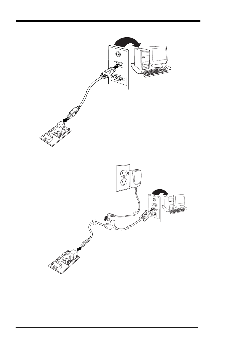
3. If using an RS-232 connection, connect the serial interface cable to
the engine and to the matching port on the back of the computer.
4. Connect the power supply connector to the serial interface cable.
Plug in the power supply.
5. Turn the terminal/computer power back on. The engine beeps.
6. If connecting the Development engine using an RS-232 interface, all
communication parameters between the engine and the terminal must
1 - 2
Page 17
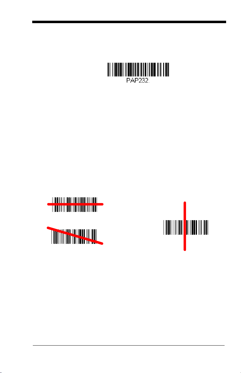
match for correct data transfer through the serial port using RS-232
RS-232 Interface
Good Read No Read
protocol. Scan the RS-232 interface bar code below. This programs
the Development engine for an RS-232 interface at 115,200 baud,
parity-none, 8 data bits, 1 stop bit, and adds a suffix of a CR LF.
7. Verify the engine operation by scanning a bar code from the Sample
Symbols in the back of this manual. The engine beeps once when a
bar code is successfully decoded.
To connect a N4313/N4315 engine to your host system, please refer to the Integration Manual.
Reading Techniques
The engine projects a bright red scan beam that corresponds to the engine’s
scanning field of view. The scan beam should be centered horizontally over the
bar code and must highlight all the vertical bars of the bar code. It will not read
if the scan beam is in any other direction.
The scan beam is smaller when the engine is closer to the code and larger
when it is farther from the code. Symbologies with smaller bars or elements (mil
size) should be read closer to the unit. Symbologies with larger bars or elements (mil size) should be read farther from the unit. To read a symbol (on a
page or on an object), hold the engine at an appropriate distance from the target and center the scan beam on the symbol. If the code being scanned is
highly reflective (e.g., laminated), it may be necessary to tilt the code up 15° to
18° to prevent unwanted reflection.
Note: At 254mm a double beam of up to 3mm is to be expected. A double beam
will not affect scanning performance and is not a product defect.
1 - 3
Page 18

Menu Bar Code Security Settings
Save Custom Defaults
Set Custom Defaults
Activate Custom Defaults
Honeywell engines are programmed by scanning menu bar codes or by sending
serial commands to the engine. If you want to restrict the ability to scan menu
codes, you can use the Menu Bar Code Security settings. Please contact the
nearest technical support office (see Limited Warranty on page 11-1) for further
information.
Setting Custom Defaults
You have the ability to create a set of menu commands as your own, custom
defaults. To do so, scan the Set Custom Defaults bar code below before each
menu command or sequence you want saved. If your command requires scanning numeric codes from the back cover, then a Save code, that entire
sequence will be saved to your custom defaults. Scan the Set Custom
Defaults code again before the next command you want saved to your custom
defaults.
When you have entered all the commands you want to save for your custom
defaults, scan the Save Custom Defaults bar code.
You may have a series of custom settings and want to correct a single setting.
To do so, just scan the new setting to overwrite the old one. For example, if you
had previously saved the setting for Beeper Volume at Low to your custom
defaults, and decide you want the beeper volume set to High, just scan the Set
Custom Defaults bar code, then scan the Beeper Volume High menu code,
and then Save Custom Defaults. The rest of the custom defaults will remain,
but the beeper volume setting will be updated.
Resetting the Custom Defaults
If you want the custom default settings restored to your engine, scan the Activate Custom Defaults bar code below. This resets the engine to the custom
default settings. If there are no custom defaults, it will reset the engine to the
factory default settings. Any settings that have not been specified through the
custom defaults will be defaulted to the factory default settings.
1 - 4
Page 19

Resetting the Factory Defaults
!
Remove Custom Defaults
Activate Defaults
This selection erases all your settings and resets the engine to the original factory defaults. It also disables all plugins.
If you aren’t sure what programming options are in your engine, or you’ve
changed some options and want to restore the engine to factory default settings, first scan the Remove Custom Defaults bar code, then scan Activate
Defaults. This resets the engine to the factory default settings.
The Serial Programming Commands, beginning on page 9-1 list the factory
default settings for each of the commands (indicated by an asterisk (*) on the
programming pages).
1 - 5
Page 20

1 - 6
Page 21

2
RS232 Interface
Programming the Interface
Introduction
This chapter describes how to program your system for the desired interface.
Programming the Interface - Plug and Play
Plug and Play bar codes provide instant set up for commonly used interfaces.
Note: After you scan one of the codes, power cycle the host terminal to have
the interface in effect.
RS232 Serial Port
The RS232 Interface bar code is used when connecting to the serial port
of a PC or terminal. The following RS232 Interface bar code also programs a carriage return (CR) and a line feed (LF) suffix, baud rate, and
data format as indicated below.
Option Setting
Baud Rate 115,200 bps
Data Format 8 data bits, no parity bit, 1 stop bit
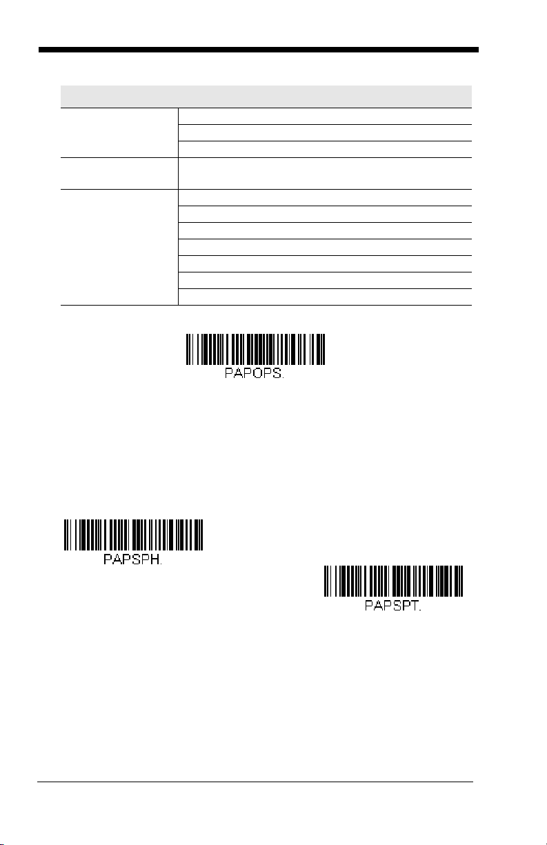
OPOS Mode
The following bar code configures your engine for OPOS (OLE for Retail
Point of Sale) by modifying the following OPOS-related settings:
Option Setting
Interface RS232
Baud Rate 38400
RS232
Handshaking
Data Bits, Stop
Bits, and Parity
Flow Control, No Timeout
XON/XOFF Off
ACK/NAK Off
8 Data, 1 Stop, Parity None
2 - 1
Page 22
Option Setting
OPOS Mode
USB IBM SurePos
(USB Handheld Scanner)
Interface
USB IBM SurePos
(USB Tabletop Scanner)
Interface
Prefix/Suffix
Clear All Prefixes and Suffixes
Add Code ID and AIM ID Prefix
Add CR Suffix
Intercharacter
Off
Delay
Symbologies Enable UPC-A with check digit and number system
Enable UPC-E0 with check digit
Enable EAN/JAN-8 with check digit
Enable EAN/JAN-13 with check digit
Enable Code 128
Enable Code 39
Enable OPOS with automatic disable off
USB IBM SurePos
Scan one of the following “Plug and Play” codes to program the engine for
an IBM SurePos (USB handheld scanner) or IBM SurePos (USB tabletop
scanner) interface.
Note: After scanning one of these codes, you must power cycle the cash
register.
2 - 2
Page 23

Each bar code above also programs the following suffixes for each symbol-
*Enable Secondary Interface
Disable Secondary Interface
U
S
B
K
e
y
b
o
a
r
d
(
P
C
)
USB Keyboard (Mac)
USB Japanese Keyboard (PC)
ogy:
Symbology Suffix Symbology Suffix
EAN 8 0C Code 39 00 0A 0B
EAN 13 16 Interleaved 2 of 5 00 0D 0B
UPC A 0D Code 128 00 18 0B
UPC E 0A Code 39 00 0A 0B
IBM Secondary Interface
On some older IBM cash registers, it may be necessary to disable the secondary or management interface. In particular, it has been found necessary on IBM registers using the 4690 V2R4 operating system. The
following bar codes are used for this purpose.
Default = Enable Secondary
Interface.
USB PC or Macintosh Keyboard
Scan one of the following codes to program the engine for USB PC Keyboard or USB Macintosh Keyboard. Scanning these codes also adds a CR
and LF.
2 - 3
Page 24

USB HID
USB HID Bar Code Scanner
HID Fallback Mode
Scan the following code to program the engine for USB HID bar code scanners.
HID Fallback Mode
If you attempt to set a USB interface for your engine, but the setup fails on
the host system, you can program the engine to fall back to a HID keyboard
interface after a set length of time. For example, if the engine is configured
for Serial Emulation Mode, but the host system does not have the correct
driver, the engine would fail. If you set the HID Fallback Mode for a set
length of time, for example, 5 minutes, the engine would change to a HID
keyboard interface after 5 minutes of trying to configure as serial emulation.
A unique beep sequence indicates that this mode has been entered. While
in HID Fallback Mode, the engine will not scan normal bar codes and
sounds a unique beep sequence that indicates the engine is in Fallback
Mode. Menu codes can still be scanned while in HID Fallback Mode, allowing you to change the engine’s programming.
Scan the bar code below, then set the length for the HID Fallback (from 060 minutes) by scanning digits from the Programming Chart, then scanning
Save.
Default = 5 minutes.
USB Serial Commands
USB Serial Emulation
Scan one of the following codes to program the engine to emulate a regular
RS232-based COM Port. If you are using a Microsoft® Windows® PC, you
will need to download a driver from the Honeywell website
(www.honeywellaidc.com). The driver will use the next available COM Port
number. Apple® Macintosh computers recognize the engine as a USB
CDC class device and automatically uses a class driver.
2 - 4
Page 25

Scanning either of these codes also adds a CR and LF.
USB Serial Emulation for
Windows XP, Windows Server
2003, and later
USB Serial Emulation for Windows 2000
CTS/RTS Emulation On
* CTS/RTS Emulation Off
Note: No extra configuration (e.g., baud rate) is necessary.
CTS/RTS Emulation
2 - 5
Page 26

ACK/NAK Mode
ACK/NAK Mode On
* ACK/NAK Mode Off
Communication Timeout
Timeout Retries
Communication Timeout
This allows you to set the length (in milliseconds) for a timeout for the host
ACK/NAK response. Scan the bar code below, then set the timeout (from
0-65535 milliseconds) by scanning digits from the Programming Chart,
then scanning Save.
Timeout Retries
This setting limits the number of Communication Timeout retries. If
the Timeout Retries is set to 0, the transmission is terminated after the
initial Communication Timeout. Scan the bar code below, then set the
number of retries (from 0-255) by scanning digits from the
Programming Chart, then scanning Save. (5 is the recommended set-
Default = 0.
ting.)
Default = 2000 ms.
2 - 6
Page 27

Communication Timeout Beeper
O
f
f
* On
NAK Retries
BEL/CAN On
* BEL/CAN Off
This selection programs the engine to issue an error beep when a
communication timeout has occurred. The error beep sound is programmed using Number of Beeps – Error (page 3-4).
Default = On.
NAK Retries
This selection limits the number of NAK retries that can occur in ACK/NAK
mode. Scan the bar code below, then set the number of retries (from 0-
255) by scanning digits from the Programming Chart, then scanning Save.
(5 is the recommended setting.)
Default = 0, or disabled.
Support BEL/CAN in ACK/NAK
This protocol responds to <BEL> and <CAN> commands when in ACK/
NAK mode. The engine sounds an error tone when a <BEL> command is
sent from the host. <CAN> terminates the transmission.
CAN Off
.
Default = BEL/
2 - 7
Page 28

Verifone® Ruby Terminal Default Settings
Verifone Ruby Settings
Gilbarco Settings
Scan the following Plug and Play code to program the engine for a Verifone
Ruby terminal. This bar code sets the baud rate to 1200 bps and the data format to 8 data bits, Mark parity, 1 stop bit and RTS/CTS no timeout. It also adds
a line feed (LF) suffix and programs the following prefixes for each symbology:
Symbology Prefix
UPC-A A
UPC-E A
EAN-8 FF
EAN-13 F
Note: If you are having unexpected results with this programming code, scan
the Activate Defaults bar code on page 1-5 first, then scan the
programming code above.
Gilbarco® Terminal Default Settings
Scan the following Plug and Play code to program the engine for a Gilbarco terminal. This bar code sets the baud rate to 2400 bps and the data format to 7
data bits, even parity, 2 stop bits. It also adds a carriage return (CR) suffix and
programs the following prefixes for each symbology:
Symbology Prefix
UPC-A A
UPC-E E0
EAN-8 FF
EAN-13 F
Note: If you are having unexpected results with this programming code, scan
the Activate Defaults bar code on page 1-5 first, then scan the
programming code above.
2 - 8
Page 29

Wincor Nixdorf Terminal Default Settings
Wincor Nixdorf Terminal Settings
Wincor Nixdorf Beetle Settings
Scan the following Plug and Play code to program the engine for a Wincor Nixdorf terminal. This bar code sets the baud rate to 9600 bps and the data format
to 8 data bits, no parity, 1 stop bit.
Note: If you are having unexpected results with this programming code, scan
the Activate Defaults bar code on page 1-5 first, then scan the
programming code above.
Wincor Nixdorf Beetle™ Terminal Default Settings
Scan the following Plug and Play code to program the engine for a Wincor Nixdorf Beetle terminal. The following prefixes are programmed for each symbology:
Symbology Prefix Symbology Prefix
Code 128 K EAN-13 A
Code 93 L GS1-128 P
Codabar N Interleaved 2 of 5 I
UPC-A A0 Plessey O
UPC-E C Straight 2 of 5 IATA H
EAN-8 B All other bar codes M
Note: If you are having unexpected results with this programming code, scan
the Activate Defaults bar code on page 1-5 first, then scan the
programming code above.
2 - 9
Page 30
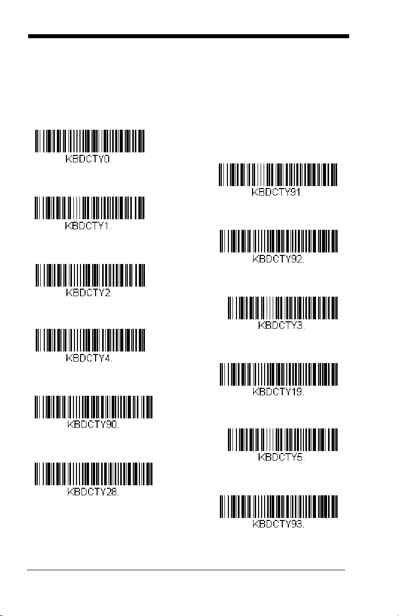
Keyboard Country Layout
* United States
Belgium
Finland
Germany
France
IBM Financial
Hungary
Arabic
Chinese
Italy
Japan ASCII
Korea
Scan the appropriate country code below to program the keyboard layout for
your country or language. As a general rule, the following characters are supported, but need special care for countries other than the United States:
@ | $ # { } [ ] = / ‘ \ < > ~
2 - 10
Page 31

Keyboard Country (continued)
United Kingdom
Turkey Q
Switzerland (German)
Russia
Slovenia
Spain
Thailand
Vietnam
Program Keyboard Country
Refer to the Honeywell website (www.honeywell.com/aidc) for complete keyboard country support information and applicable interfaces. If you need to program a keyboard for a country other than one listed above, scan the Program
Keyboard Country bar code below, then scan the numeric bar code(s) for the
appropriate country from the inside back cover, then the Save bar code.
2 - 11
Page 32

Keyboard Wedge Modifiers
* Off
3 Characters
4 Characters
* Regular
Caps Lock
ALT Mode
If your bar code contains special characters from the extended ASCII chart
for example, an e with an accent grave (è), you will use ALT Mode. (See
Extended ASCII Characters on page A-6.)
Note: Scan the ALT mode bar code after scanning the appropriate
Keyboard Country code.
If your keystrokes require using the ALT key and 3 characters, scan the 3
Characters bar code. If your keystrokes require the ALT key and 4 characters, scan the 4 Characters bar code. The data is then output with the
special character(s).
Keyboard Style
This programs keyboard styles, such as Caps Lock and Shift Lock. If you
have used Keyboard Conversion settings, they will override any of the following Keyboard Style settings.
Regular is used when you normally have the Caps Lock key off.
Default = Off.
Default = Regular.
Caps Lock
2 - 12
is used when you normally have the Caps Lock key on.
Page 33

Shift Lock is used when you normally have the Shift Lock key on (not com-
Shift Lock
Autocaps via NumLock
Emulate External Keyboard
mon to U.S. keyboards).
Autocaps via NumLock
Germany, France) where the Caps Lock key cannot be used to toggle Caps
Lock. The NumLock option works similarly to the regular Autocaps, but
uses the NumLock key to retrieve the current state of the Caps Lock.
Emulate External Keyboard should be scanned if you do not have an
external keyboard (IBM AT or equivalent).
bar code should be scanned in countries (e.g.,
Note: After scanning the Emulate External Keyboard bar code, you must
power cycle your computer.
Keyboard Conversion
Alphabetic keyboard characters can be forced to be all upper case or all
lowercase. So if you have the following bar code: “abc569GK,” you can
make the output “ABC569GK” by scanning Convert All Characters to
Upper Case, or to “abc569gk” by scanning Convert All Characters to
Lower Case. These settings override Keyboard Style selections.
2 - 13
Page 34

Default = Keyboard Conversion Off
* Keyboard Conversion Off
Convert All Characters to Upper
Case
Convert All Characters to Lower
Case
.
Keyboard Modifiers
This modifies special keyboard features, such as CTRL+ ASCII codes and
Turbo Mode.
Control + ASCII Mode On: The engine sends key combinations for ASCII
control characters for values 00-1F (refer to the ASCII chart for ASCII
Conversion Chart, page A-3). Windows is the preferred mode. All key-
board country codes are supported. DOS mode is a legacy mode, and it
does not support all keyboard country codes. New users should use the
Windows mode.
Windows Mode Prefix/Suffix Off: The engine sends key combinations
for ASCII control characters for values 00-1F (refer to the ASCII chart for
ASCII Conversion Chart, page A-3), but it does not transmit any prefix or
suffix information.
2 - 14
Page 35

Default = Control + ASCII Mode Off.
Windows Mode Control + ASCII
Mode On
* Control + ASCII Mode Off
DOS Mode Control + ASCII Mode
On
Windows Mode Prefix/Suffix Off
Numeric Keypad Mode On
* Numeric Keypad Mode Off
Numeric Keypad Mode: Sends numeric characters as if entered from a
numeric keypad.
Default = Off.
2 - 15
Page 36

RS232 Modifiers
300
2400
600
1200
4800
38400
* 9600
19200
115,200
57,600
RS232 Baud Rate
Baud Rate sends the data from the engine to the terminal at the specified
rate. The host terminal must be set for the same baud rate as the engine.
Default = 9600.
2 - 16
Page 37

RS232 Word Length: Data Bits, Stop Bits,
7 Data, 1 Stop, Parity Even
7 Data, 1 Stop, Parity None
7 Data, 1 Stop, Parity Odd
7 Data, 2 Stop, Parity Even
7 Data, 2 Stop Parity None
* 8 Data, 1 Stop, Parity None
8 Data, 1 Stop, Parity Even
7 Data, 2 Stop, Parity Odd
8 Data, 1 Stop, Parity Odd
7 Data, 1 Stop, Parity Space
and Parity
Data Bits sets the word length at 7 or 8 bits of data per character. If an
application requires only ASCII Hex characters 0 through 7F decimal (text,
digits, and punctuation), select 7 data bits. For applications that require
use of the full ASCII set, select 8 data bits per character.
Stop Bits sets the stop bits at 1 or 2.
Parity provides a means of checking character bit patterns for validity.
Default = None.
Default = 8.
Default = 1.
2 - 17
Page 38

RS232 Handshaking
7 Data, 2 Stop, Parity Space
8 Data, 1 Stop, Parity Space
7 Data, 1 Stop, Parity Mark
7 Data, 2 Stop, Parity Mark
8 Data, 1 Stop Parity Mark
RS232 Handshaking allows control of data transmission from the engine
using software commands from the host device.
RTS/CTS Off: RTS/CTS is turned off so no data flow control is used, but
RTS is still active.
RTS/CTS Off, RTS Inactive: RTS/CTS is turned off so no data flow control is used and RTS is inactive.
Flow Control, No Timeout: The engine asserts RTS when it has data to
send, and will wait indefinitely for CTS to be asserted by the host.
Character-Based Flow Control, No Timeout: The engine asserts RTS
when it has a character to send, and will wait indefinitely for CTS to be
asserted by the host
Two-Direction Flow Control: The engine asserts RTS when it is OK for
the host to transmit. The host asserts CTS when it is OK for the device to
transmit.
Flow Control with Timeout: The engine asserts RTS when it has data to
send and waits for a delay (see RS232 Timeout on page 2-19) for CTS to
be asserted by the host. If the delay time expires and CTS is not asserted,
the device transmit buffer is cleared and scanning may resume.
2 - 18
Page 39

Character-Based Flow Control with Timeout: The engine asserts RTS
Flow Control, No Timeout
* RTS/CTS Off, RTS Active
Two-Direction Flow Control
Flow Control with Timeout
Character-Based Flow Control
with Timeout
Character-Based Flow Control,
No Timeout
RTS/CTS Off, RTS Inactive
RS232 Timeout
when it has a character to send and waits for a delay (see RS232 Timeout
on page 2-19) for CTS to be asserted by the host. If the delay time expires
and CTS is not asserted, the device transmit buffer is cleared and scanning
may resume.
Default =RTS/CTS Off, RTS Active.
RS232 Timeout
When using Flow Control with Timeout, you must program the length of the
delay you want to wait for CTS from the host. Set the length (in milliseconds) for a timeout by scanning the bar code below, then setting the timeout (from 1-5100 milliseconds) by scanning digits from the Programming
Chart, then scanning Save.
Default = 1000 ms (1 second).
2 - 19
Page 40

XON/XOFF
* XON/XOFF Off
XON/XOFF On
ACK/NAK On
* ACK/NAK Off
Communication Timeout
Standard ASCII control characters can be used to tell the engine to start
sending data (XON/XOFF On) or to stop sending data (XON/XOFF Off).
When the host sends the XOFF character (DC3, hex 13) to the engine,
data transmission stops. To resume transmission, the host sends the XON
character (DC1, hex 11). Data transmission continues where it left off
when XOFF was sent.
Default = XON/XOFF Off
.
ACK/NAK
After transmitting data, the engine waits for an ACK character (hex 06) or a
NAK character (hex 15) response from the host. If ACK is received, the
communications cycle is completed and the engine looks for more bar
codes. If NAK is received, the last set of bar code data is retransmitted and
the engine waits for ACK/NAK again. Turn on the ACK/NAK protocol by
scanning the ACK/NAK On bar code below. To turn off the protocol, scan
ACK/NAK Off.
Default = ACK/NAK Off
.
Communication Timeout
This allows you to set the length (in milliseconds) for a timeout for the host
ACK/NAK response. Scan the bar code below, then set the timeout (from
1-65535 milliseconds) by scanning digits from the Programming Chart,
then scanning Save.
2 - 20
Default = 2000 ms.
Page 41

Timeout Retries
Timeout Retries
O
f
f
* On
NAK Retries
This setting limits the number of Communication Timeout retries. If the
Timeout Retries is set to 0, the transmission is terminated after the initial Communication Timeout. Scan the bar code below, then set the
number of retries (from 0-255) by scanning digits from the
Programming Chart, then scanning Save. (5 is the recommended set-
Default = 0.
ting.)
Communication Timeout Beeper
This selection programs the engine to issue an error beep when a
communication timeout has occurred. The error beep sound is programmed using Number of Beeps – Error (page 3-4).
Default = On.
NAK Retries
This selection limits the number of NAK retries that can occur in ACK/NAK
mode. Scan the bar code below, then set the number of retries (from 0-
255) by scanning digits from the Programming Chart, then scanning Save.
(5 is the recommended setting.)
Default = 0, or disabled.
2 - 21
Page 42

Support BEL/CAN in ACK/NAK
BEL/CAN On
* BEL/CAN Off
RS232 Defaults
This protocol responds to <BEL> and <CAN> commands when in ACK/
NAK mode. The engine sounds an error tone when a <BEL> command is
sent from the host. <CAN> terminates the transmission.
CAN Off
.
Default = BEL/
RS232 Defaults
If you want the custom RS232 default settings restored to your engine,
scan the RS232 Defaults bar code below. This resets the engine to the
custom default settings (see Setting Custom Defaults on page 1-4). If
there are no custom defaults, it will reset the engine to the factory default
settings. Any settings that have not been specified through the custom
defaults will be restored to the factory default settings.
2 - 22
Page 43

3
Power Up Beeper Off -
Engine
* Power Up Beeper On -
Engine
*Beep on BEL Off
Beep on BEL On
Input/Output Settings
Power Up Beeper
The engine can be programmed to beep when it’s powered up. If you are using
a cordless system, the base can also be programmed to beep when it is powered up. Scan the Off bar code(s) if you don’t want a power up beep.
Power Up Beeper On - Engine.
Beep on BEL Character
You may wish to force the engine to beep upon a command sent from the host.
If you scan the following Beep on BEL On bar code, the engine will beep every
time a BEL character is received from the host.
Default = Beep on BEL Off.
Default =
3 - 1
Page 44

Good Read and Error Indicators
* Beeper - Good Read On
Beeper - Good Read Off
Low (1600 Hz)
* Medium (2350 Hz)
High (4200 Hz)
Beeper – Good Read
The beeper may be programmed On or Off in response to a good read.
Turning this option off, only turns off the beeper response to a good read
indication. All error and menu beeps are still audible.
Good Read On.
Beeper Pitch – Good Read
The beeper pitch codes modify the pitch (frequency) of the beep the engine
emits on a good read.
Default = Medium.
Default = Beeper -
3 - 2
Page 45

Beeper - Transmit Order
* Before Transmission
After Transmission
* Razz (100 Hz)
Medium (2000 Hz)
High (4200 Hz)
* Normal Beep
Short BeepShort Beep
The beeper transmit order determines when the good read beep occurs.
The engine can be set to emit the good read beep either before or after
data transmission.
Default = Before Transmission.
Beeper Pitch – Error
The beeper pitch codes modify the pitch (frequency) of the sound the
engine emits when there is a bad read or error.
Default = Razz.
Beeper Duration – Good Read
The beeper duration codes modify the length of the beep the engine emits
on a good read.
Default = Normal.
3 - 3
Page 46

Number of Beeps – Good Read
Number of Good Read Beeps/LED Flashes
Number of Error Beeps/LED Flashes
The number of beeps of a good read can be programmed from 1 - 9. The
same number of beeps will be applied to the beeper and LED in response
to a good read. For example, if you program this option to have five beeps,
there will be five beeps and five LED flashes in response to a good read.
The beeps and LED flashes are in sync with one another.
Note: The LEDs can also be programmed separately. See LED
Settings on page 3-5.
To change the number of beeps, scan the following bar code and then scan
a digit (1-9) bar code and the Save bar code on the Programming Chart
inside the back cover of this manual.
Default = 1.
Number of Beeps – Error
The number of beeps and LED flashes emitted by the engine for a bad
read or error can be programmed from 1 - 9. For example, if you program
this option to have five error beeps, there will be five error beeps and five
LED flashes in response to an error.
Note: The LEDs can also be programmed separately. See LED
Settings on page 3-5.
To change the number of error beeps, scan the following bar code and then
scan a digit (1-9) bar code and the Save bar code on the Programming
Chart inside the back cover of this manual.
Default = 1.
LED Indicators
The external LED can be programmed to be On or Off. Use the following bar
codes to program the external LED indicators.
Scan.
Note: The external LED refers to the signal Good Read LED and is not a
physical LED on the engine.
3 - 4
Default = LED On with Good
Page 47

LED Settings
LED Off
* LED On with Good Scan
LED On with Laser
LED On when CodeGate
Disabled
LED On with CTS
Activation Defaults
Activation Settings
Caution: When working with Activation settings, enable the settings you
want before disabling those you do not want to use. If you
disable settings first, you may program the engine so it is unable
to read bar codes. if this happens, power cycle the engine and
scan the defaults bar code on page 1-4.
Activation Defaults
If you want the Activation default settings restored to your engine, scan the
Activation Defaults bar code below. The engine will reset to the custom
default settings (see Setting Custom Defaults on page 1-4). If there are no
custom defaults, it will reset the engine to the factory default settings. Any
settings that have not been specified through the custom defaults will be
defaulted to the factory default settings.
3 - 5
Page 48

Presentation Modes
Presentation Mode with
CodeGate
Presentation Mode
* Manual Activation Mode On
Manual Activation Mode Off
By default you must press the external trigger to read a bar code. Use the
following commands to adjust how the engine behaves.
Presentation Mode: The engine automatically detects bar codes, then
scans and transmits the data. The laser turns off afterward.
Presentation Mode with CodeGate®: The engine automatically detects
bar codes and decodes them. However, the data is not transmitted until
you press the external trigger. The laser remains on briefly after the transmission.
Manual Activation Mode
In Manual Activation Mode, you must press the external trigger to scan a
bar code. The engine scans until a bar code is read, or until the external
trigger is released.
Default = Manual Activation On.
End Manual Activation After Good Read
After a bar code is successfully read, the laser can be programmed either
to remain on and scanning, or to turn off. When End Manual Activation
After Good Read is enabled, the laser turns off and stops scanning after a
good read. If you scan Do Not End Manual Activation After Good Read,
3 - 6
Page 49

the laser remains on after a good read, but the external trigger must be
* End Manual Activation After
Good Read
Do Not End Manual Activation
After Good
Laser Timeout - External
Trigger Release
Laser Timeout - External
Trigger Hold
pressed to scan the next bar code.
Default = End Manual Activation After
Good Read.
Manual Activation Laser Timeout External Trigger Settings
You can set a timeout for the length of time the laser remains on and
attempting to decode bar codes when the external trigger is held down, and
after it is released. Set the length (in milliseconds) for a timeout by scanning one of the following bar codes, then setting the timeout (from 1-65535
milliseconds) by scanning digits from the Programming Chart, then scanning Save.
Release 0.
Default = External Trigger Hold 5000 ms, External Trigger
3 - 7
Page 50

CodeGate
* CodeGate On
CodeGate Off
Object Detection Mode On
* Object Detection Mode Off
When CodeGate is On, the external trigger is used to allow decoded data
to be transmitted to the host system. The engine remains on, scanning
and decoding bar codes, but the bar code data is not transmitted until the
external trigger is pressed. When CodeGate is Off, bar code data is transmitted when it is decoded.
®
Default = CodeGate On.
Object Detection Mode
Object Detection Mode uses an LED to detect when an object is in the
engine’s field of view. When an object is detected, the laser turns on and
the engine attempts to scan the bar code.
Mode Off.
Default = Object Detection
End Object Detection After Good Read
After a bar code is successfully detected and read from the engine, the
laser can be programmed either to remain on and scanning, or to turn off.
When End Object Detection After Good Read is enabled, the laser turns
3 - 8
Page 51

off and stops scanning after a good read. If you scan Do Not End Object
* End Object Detection After
Good Read
Do Not End Object Detection
After Good Read
Object Detection Laser
Timeout
* Long
Short
Detection After Good Read, the laser remains on after a good read.
Default = End Object Detection After Good Read.
Object Detection Laser Timeout
You can set a timeout for the length of time the laser remains on and
attempting to decode bar codes after an object is detected. Set the length
(in milliseconds) for a timeout by scanning the following bar code, then setting the timeout (from 1-65535 milliseconds) by scanning digits from the
Programming Chart, then scanning Save.
Note: After an object detection timeout has occurred and there is no good
read, the laser and flipper will turn off. The laser and flipper can be
turned on by moving an object in and out of the object detection
range. If the engine is configured for button activation, pushing the
button can also turn the laser and flipper back on.
Default = 5000 ms.
Object Detection Distance
When the engine is in the stand and you are using Object Detection Mode,
you can set the distance range for detecting objects. Short sets the engine
to detect objects approximately 5 inches (12.7cm) away from the nose.
Long sets it to detect objects approximately 10 inches (25.4cm) away.
Default = Long.
3 - 9
Page 52

Character Activation Mode
* Off
On
Activation Character
You may use a character sent from the host to trigger the engine to begin scanning. When the activation character is received, the engine continues scanning
until either the Character Activation Laser Timeout (page 3-11), the deactivation character is received (see Deactivation Character on page 3-11), or a bar
code is transmitted. Scan the following On bar code to use character activation,
then use Activation Character (following) to select the character you will send
from the host to start scanning.
Activation Character
This sets the character used to trigger scanning when using Character
Activation Mode. On the ASCII Conversion Chart, page A-3, find the hex
value that represents the character you want to use to trigger scanning.
Scan the following bar code, then use the Programming Chart to read the
alphanumeric combination that represents that ASCII character. Scan
Save to finish.
Default = Off.
End Character Activation After Good Read
After a bar code is successfully detected and read from the engine, the
laser can be programmed either to remain on and scanning, or to turn off.
When End Character Activation After Good Read is enabled, the laser
3 - 10
Page 53

turns off and stops scanning after a good read. If you scan Do Not End
* End Character Activation After
Good Read
Do Not End Character Activation
After Good Read
Character Activation Laser
Timeout
* Off
On
Character Activation After Good Read, the laser remains on after a good
Default = End Character Activation After Good Read.
read.
Character Activation Laser Timeout
You can set a timeout for the length of time the laser remains on and
attempting to decode bar codes when using Character Activation Mode.
Set the length (in milliseconds) for a timeout by scanning the following bar
code, then setting the timeout (from 1-65535 milliseconds) by scanning digits from the Programming Chart, then scanning Save.
Default = 5000 ms.
Character Deactivation Mode
If you have sent a character from the host to trigger the engine to begin scanning, you can also send a deactivation character to stop scanning. Scan the following On bar code to use character deactivation, then use Deactivation
Character (following) to select the character you will send from the host to terminate scanning.
Default = Off.
Deactivation Character
This sets the character used to terminate scanning when using Character
Deactivation Mode. On the ASCII Conversion Chart, page A-3, find the hex
value that represents the character you want to use to terminate scanning.
3 - 11
Page 54

Scan the following bar code, then use the Programming Chart to read the
Deactivation Character
Short (500 ms)
* Medium (750 ms)
Long (1000 ms)
Extra Long (2000 ms)
User-Specified Reread Delay
alphanumeric combination that represents that ASCII character. Scan
Save to finish.
Reread Delay
This sets the time period before the engine can read the
ond time. Setting a reread delay protects against accidental rereads of the
same bar code. Longer delays are effective in minimizing accidental rereads.
Use shorter delays in applications where repetitive bar code scanning is
required.
Default = Medium.
same
bar code a sec-
User-Specified Reread Delay
If you want to set your own length for the reread delay, scan the following bar
code, then set the delay (from 0-30,000 milliseconds) by scanning digits from
the Programming Chart, then scanning Save.
3 - 12
Page 55

Centering
Centering On
* Centering Off
Left of Centering Window
Right of Centering Window
* Blinky Mode Off
Blinky Mode On
Blinky Always On/Continuous
Use Centering to narrow the engine’s field of view to make sure the engine
reads only those bar codes intended by the user. For instance, if multiple codes
are placed closely together, centering will insure that only the desired codes are
read.
Scan Centering On, then scan one of the following bar codes to change the left
or right of the centering window. To set the the percent you want to shift the
centering window scan the digits from the Programming Chart, then scanning
Default = 40% Left and 60% Right.
Save.
Note: Centering is dependent on the orientation of the engine. If the engine is
inverted, right becomes left and left becomes right.
Blinky Mode
Blinky Mode can be activated by Object Detection or the External Trigger.
When the Blinky Mode On or Blinky Always On/Continuous bar codes are
scanned, the scan engine blinks on and off at 50% duty cycle (250 milliseconds
on, then 250 milliseconds off.)
Default = Blinky Mode Off.
3 - 13
Page 56

Laser Scan Angle
* Full Laser Beam Sweep (48°)
Reduced Laser Beam Sweep
(35°)
* Low
Low/Medium
Medium/High
High
Continuous Scan Mode
The laser scan angle can be set to Reduced Laser Beam Sweep (35°) or Full
Laser Beam Sweep (48°). Laser Scan Angle is not available for wide angle
models.
Default = Full Laser Beam Sweep (48°).
Decode Security
This selection allows you to adjust the decode security needed while scanning.
For good quality codes, choose Low to achieve fast scan speed. For codes
prone to misreads, choose High.
Note: Increasing the security level may decrease the scan speed.
Default = Low.
Continuous Scan Mode
This programs the engine to continuously scan and decode, with the laser and
motor staying on.
3 - 14
Page 57

Power Save Mode Timeout
Power Save Timeout
* 600 Seconds
* Off
Sleep Mode
Hibernate
This allows you to set the length (in seconds) for power save timeout. To set the
length scan the Power Save Timeout bar code below, then set the timeout
(from 0-65535 seconds) by scanning digits from the Programming Chart, then
scanning Save. The scan engine goes into a power save mode (Sleep or Hibernate) at timeout after a successful scan or the duration of inactivity.
600 seconds.
Default =
Power Save Mode
The scan engine has three Power Save Modes: Off, Sleep Mode, and Hibernate. In Off mode, all components are powered on and the scan engine is in
operating mode. In Sleep Mode, the laser, motor, and micro are powered off.
In Hibernate, all components are powered off. The scan engine enters Power
Save Mode after the timeout occurs. See Power Save Mode Timeout on page
3-15 for further information.
Default = Off.
Aimer Control
To control engine’s aimer before and after scanning or to control the aimer with
an external aiming pin, scan one of the bar codes below.
Always Off.
Default = Aimer
3 - 15
Page 58

When Aimer on 100 milliseconds is selected, the aimer is on for 100 millisec-
* Aimer Always Off
Aimer Always On
Aimer Controlled by External AIming Pin
Aimer on 100 milliseconds
Before Activation
onds before the scan engine starts normal scanning operation.
Note: Aimer is not available in Class 1 Laser models.
User-Specified Aimer Delays
If you want to set your own length for the duration of the delay
vation, scan the Before Activation bar code below, then set the time-out
by scanning digits (0-65535 seconds) from the Programming Chart, then
scanning Save. Default = 0 seconds.
3 - 16
before
acti-
Page 59

If you want to set your own length for the duration of the delay
After Activation
tion, scan the After Activation bar code below, then set the time-out by
scanning digits (0-65535 seconds) from the Programming Chart, then
scanning Save. Default = 0 seconds.
after
Output Sequence Overview
Require Output Sequence
When turned off, the bar code data will be output to the host as the engine
decodes it. When turned on, all output data must conform to an edited
sequence or the engine will not transmit the output data to the host device.
See Require Output Sequence on page 3-21 for further information.
Output Sequence Editor
This programming selection allows you to program the engine to output
data (when scanning more than one symbol) in whatever order your application requires, regardless of the order in which the bar codes are
scanned. Reading the
the following Universal values. These are the defaults. Be certain you
want to delete or clear all formats before you read the
symbol.
Note: If CodeGate is enabled, you must hold the external trigger down
while reading each bar code in a sequence.
Default Sequence
symbol programs the engine to
Default Sequence
activa-
Note: To make Output Sequence Editor selections, you’ll need to know the
code I.D., code length, and character match(es) your application
requires. Use the Alphanumeric symbols on the Programming Chart
to read these options.
To Add an Output Sequence
1. Scan the
Sequence, page 3-21).
2. Code I.D.
On the Symbology Charts on page A-1, find the symbology to which you
want to apply the output sequence format. Locate the Hex value for that
symbology and scan the 2 digit hex value from the Programming Chart
(inside back cover).
3. Length
Specify what length (up to 9999 characters) of data output will be
acceptable for this symbology. Scan the four digit data length from the
Programming Chart. (Note: 50 characters is entered as 0050. 9999 is
Enter Sequence
symbol (see Require Output
3 - 17
Page 60

a universal number, indicating all lengths.) When calculating the length,
A - Code 39
B - Code 128
C - Code 93
you must count any programmed prefixes, suffixes, or formatted
characters as part of the length (unless using 9999).
4. Character Match Sequences
On the ASCII Conversion Chart, page A-3, find the Hex value that
represents the character(s) you want to match. Use the Programming
Chart to read the alphanumeric combination that represents the ASCII
characters. (99 is the Universal number, indicating all characters.)
5. End Output Sequence Editor
F F
Scan
Save
to enter an Output Sequence for an additional symbology, or
to save your entries.
Other Programming Selections
•
Discard
This exits without saving any Output Sequence changes.
Output Sequence Example
In this example, you are scanning Code 93, Code 128, and Code 39 bar
codes, but you want the engine to output Code 39 1st, Code 128 2nd, and
Code 93 3rd, as shown below.
Note: Code 93 must be enabled to use this example.
You would set up the sequence editor with the following command line:
SEQBLK62999941FF6A999942FF69999943FF
The breakdown of the command line follows:
SEQBLKsequence editor start command
62 code identifier for Code 39
9999 code length that must match for Code 39, 9999 = all lengths
41 start character match for Code 39, 41h = “A”
FF termination string for first code
3 - 18
Page 61

6A code identifier for Code 128
9999 code length that must match for Code 128, 9999 = all lengths
42 start character match for Code 128, 42h = “B”
FF termination string for second code
69 code identifier for Code 93
9999 code length that must match for Code 93, 9999 = all lengths
43 start character match for Code 93, 43h = “C”
FF termination string for third code
To program the previous example using specific lengths, you would have to
count any programmed prefixes, suffixes, or formatted characters as part of
the length. If you use the example on page 3-18, but assume a <CR> suffix
and specific code lengths, you would use the following command line:
SEQBLK62001241FF6A001342FF69001243FF
The breakdown of the command line follows:
SEQBLKsequence editor start command
62 code identifier for Code 39
0012 A - Code 39 sample length (11) plus CR suffix (1) = 12
41 start character match for Code 39, 41h = “A”
FF termination string for first code
6A code identifier for Code 128
0013 B - Code 128 sample length (12) plus CR suffix (1) = 13
42 start character match for Code 128, 42h = “B”
FF termination string for second code
69 code identifier for Code 93
0012 C - Code 93 sample length (11) plus CR suffix (1) = 12
43 start character match for Code 93, 43h = “C”
FF termination string for third code
3 - 19
Page 62

Output Sequence Editor
Default Sequence
Enter Sequence
Sequence Timeout
Sequence Match Beeper Off
* Sequence Match Beeper On
Sequence Timeout
You may wish to set the maximum time between bar code scans in an output sequence. If that maximum time is not met, the output sequence operation is terminated. Set the length (in milliseconds) for a timeout by
scanning the following bar code, then setting the timeout (from 1-65535
milliseconds) by scanning digits from the Programming Chart, then scanning Save.
Default = 5000 msec.
Sequence Match Beeper
By default, the engine beeps when a sequence match is found. If you want
the engine to remain silent, scan the following Sequence Match Beeper
Off bar code.
Default = Sequence Match Beeper On.
Partial Sequence
If an output sequence operation is terminated before all your output
sequence criteria are met, the bar code data acquired to that point is a
“partial sequence.”
Scan Discard Partial Sequence to discard partial sequences when the
output sequence operation is terminated before completion.
3 - 20
Page 63

Scan Transmit Partial Sequence to transmit partial sequences. (Any
Transmit Partial Sequence
* Discard Partial Sequence
Required
On/Not Required
*Off
fields in the sequence where no data match occurred will be skipped in the
output.)
the timeout is reached, the partial sequence is transmitted.
If you have programmed a Sequence Timeout (page 3-20) and
Default = Dis-
card Partial Sequence.
Require Output Sequence
When an output sequence is Required, all output data must conform to an
edited sequence or the engine will not transmit the output data to the host
device. When it’s On/Not Required, the engine will attempt to get the output data to conform to an edited sequence but, if it cannot, the engine
transmits all output data to the host device as is.
Off
When the output sequence is
the engine decodes it.
Default = Off.
, the bar code data is output to the host as
3 - 21
Page 64

No Read
On
* Off
With No Read turned On, the engine notifies you if a code cannot be read. If
using an EZConfig-Scanning Tool Scan Data Window (see page 8-2), an “NR”
appears when a code cannot be read. If No Read is turned Off, the “NR” will
not appear.
If you want a different notation than “NR,” for example, “Error,” or “Bad Code,”
you can edit the output message (see Data Formatting beginning on page 5-1).
The hex code for the No Read symbol is 9C.
Default = Off.
3 - 22
Page 65

4
Data Editing
Prefix/Suffix Overview
When a bar code is scanned, additional information is sent to the host computer
along with the bar code data. This group of bar code data and additional,
user-defined data is called a “message string.” The selections in this section
are used to build the user-defined data into the message string.
Prefix and Suffix characters are data characters that can be sent before and
after scanned data. You can specify if they should be sent with all symbologies,
or only with specific symbologies. The following illustration shows the breakdown of a message string:
Prefix
alpha numeric &
control characters
Scanned Data
variable length1-11
Suffix
1-11
alpha numeric &
control characters
Points to Keep In Mind
• It is not necessary to build a message string. The selections in this
chapter are only used if you wish to alter the default settings.
prefix = None. Default suffix is dependent on interface
• A prefix or suffix may be added or cleared from one symbology or all
symbologies.
• You can add any prefix or suffix from the ASCII Conversion Chart,
beginning on page A-3, plus Code I.D. and AIM I.D.
• You can string together several entries for several symbologies at one
time.
• Enter prefixes and suffixes in the order in which you want them to appear
on the output.
• When setting up for specific symbologies (as opposed to all
symbologies), the specific symbology ID value counts as an added prefix
or suffix character.
• The maximum size of a prefix or suffix configuration is 32 characters,
which includes header information.
.
Default
To Add a Prefix or Suffix:
Step 1. Scan the Add Prefix or Add Suffix symbol (page 4-3).
Step 2. Determine the 2 digit Hex value from the Symbology Chart
(included in the Symbology Charts, beginning on page A-1) for the
4 - 1
Page 66

symbology to which you want to apply the prefix or suffix. For
example, for Code 128, Code ID is “j” and Hex ID is “6A”.
Step 3. Scan the 2 hex digits from the Programming Chart inside the back
cover of this manual or scan 9, 9 for all symbologies.
Step 4. Determine the hex value from the ASCII Conversion Chart on page
A-3, for the prefix or suffix you wish to enter.
Step 5. Scan the 2 digit hex value from the Programming Chart inside the
back cover of this manual.
Step 6. Repeat Steps 4 and 5 for every prefix or suffix character.
Step 7. To add the Code I.D., scan 5, C, 8, 0.
To add AIM I.D., scan 5, C, 8, 1.
To add a backslash (\), scan 5, C, 5, C.
Note: To add a backslash (\) as in Step 7, you must scan 5C twice – once
to create the leading backslash and then to create the backslash
itself.
Step 8. Scan Save to exit and save, or scan Discard to exit without saving.
Repeat Steps 1-6 to add a prefix or suffix for another symbology.
Example: Add a Suffix to a specific symbology
To send a CR (carriage return)Suffix for U.P.C. only:
Step 1. Scan Add Suffix.
Step 2. Determine the 2 digit hex value from the Symbology Chart
(included in the Symbology Charts, beginning on page A-1) for
U.P.C.
Step 3. Scan 6, 3 from the Programming Chart inside the back cover of this
manual.
Step 4. Determine the hex value from the ASCII Conversion Chart on page
A-3, for the CR (carriage return).
Step 5. Scan 0, D from the Programming Chart inside the back cover of this
manual.
Step 6. Scan Save, or scan Discard to exit without saving.
To Clear One or All Prefixes or Suffixes
You can clear a single prefix or suffix, or clear all prefixes/suffixes for a
symbology. If you have been entering prefixes and suffixes for single symbologies, you can use Clear One Prefix (Suffix) to delete a specific char-
acter from a symbology. When you Clear All Prefixes (Suffixes), all the
prefixes or suffixes for a symbology are deleted.
4 - 2
Page 67

Step 1. Scan the Clear One Prefix or Clear One Suffix symbol.
Add CR Suffix
All Symbologies
Add Prefix
Clear One Prefix
Clear All Prefixes
Step 2. Determine the 2 digit Hex value from the Symbology Chart
(included in the Symbology Charts, beginning on page A-1) for the
symbology from which you want to clear the prefix or suffix.
Step 3. Scan the 2 digit hex value from the Programming Chart inside the
back cover of this manual or scan 9, 9 for all symbologies.
Your change is automatically saved.
To Add a Carriage Return Suffix to All Symbologies
Scan the following bar code if you wish to add a carriage return suffix to all
symbologies at once. This action first clears all current suffixes, then programs a carriage return suffix for all symbologies.
Prefix Selections
4 - 3
Page 68

Suffix Selections
Add Suffix
Clear One Suffix
Clear All Suffixes
* Transmit Alternate Extended
ASCII
Transmit Normal Extended
ASCII
Transmit Alternate Extended ASCII Characters
You may need to emulate special keyboard functions, such as up or down
arrows, Alt/Make or Alt/Break commands, that are not supported in the
Extended ASCII Character table. Refer to Alternate Extended ASCII
Characters (page 4-5) for a range of keyboard function keys and corresponding
decimal and hex characters. If you scan the Transmit Alternate Extended
ASCII code, any hex entries in a prefix or suffix will result in the corresponding
Keyboard Function output.
Example: Transmit Alternate Extended ASCII is enabled, and you scan Add
When Transmit Normal Extended ASCII is selected, the normal extended
ASCII character is transmitted (see ASCII Conversion Chart on page A-3).
Example: Transmit Normal Extended ASCII is enabled, and you scan Add
Default = Transmit Alternate Extended ASCII.
Suffix, then scan 9 9 8 9. All symbologies (99) would have a suffix
of a Page Down (hex 89) added to them.
Suffix, then scan 9 9 8 9. All symbologies (99) would have a suffix
‰ character added to them.
of a
4 - 4
Page 69

Alternate Extended ASCII Characters
DEC HEX Keyboard Function DEC HEX Keyboard Function
128 80
129 81
130 82
131 83
132 84 Insert 156 9C Numeric Keypad +
133 85 Delete 157 9D Numeric Keypad 134 86 Home 158 9E Numeric Keypad *
135 87 End 159 9F Caps Lock
136 88 Page Up 160 A0 Num Lock
137 89 Page Down 161 A1 Left Alt
138 8A Right ALT 162 A2 Left Ctrl
139 8B Right CTRL 163 A3 Left Shift
140 8C Reserved 164 A4 Right Shift
141 8D Reserved 165 A5 Print Screen
142 8E Numeric Keypad Enter 166 A6 Ta b
143 8F Numeric Keypad / 167 A7 Shift Tab
144 90 F1 168 A8 Enter
145 91 F2 169 A9 Esc
146 92 F3 170 AA Alt Make
147 93 F4 171 AB Alt Break
148 94 F5 172 AC Control Make
149 95 F6 173 AD Control Break
150 96 F7 174 AE Alt Sequence with 1 Character
151 97 F8 175 AF Ctrl Sequence with 1 Character
up arrow ↑
down arrow ↓
right arrow →
left arrow ←
152 98 F9
153 99 F10
154 9A F11
155 9B F12
4 - 5
Page 70

Function Code Transmit
* Enable
Disable
* None
LRC Starts on 1st Character
LRC Starts on 2nd Character
CRC
When this selection is enabled and function codes are contained within the
scanned data, the engine transmits the function code to the terminal. Charts of
these function codes are provided in Supported Interface Keys starting on
page 7-2. When the engine is in keyboard wedge mode, the scan code is con-
verted to a key code before it is transmitted.
Default = Enable.
Communication Check Character
To enhance security, you can specify the transmission type of a check character; either LRC where the calculation starts on the first transmitted character,
LRC where the calculation starts on the second transmitted character, or CRC.
Note: This option adds a check character to the bar code data for all
symbologies. If you need to enable or disable check characters for
individual symbologies, see Symbologies beginning on page 6-1.
Scan the following bar code to set the communication check character type.
Default = None.
4 - 6
Page 71

Intercharacter, Interfunction, and
1 2345
Intercharacter Delay
Prefix Scanned Data Suffix
Intercharacter Delay
Intermessage Delays
Some terminals drop information (characters) if data comes through too quickly.
Intercharacter, interfunction, and intermessage delays slow the transmission of
data, increasing data integrity.
Intercharacter Delay
An intercharacter delay of up to 5000 milliseconds (in 5ms increments) may
be placed between the transmission of each character of scanned data.
Scan the following Intercharacter Delay bar code, then scan the number
of 5ms delays, and the Save bar code using the Programming Chart inside
the back cover of this manual.
To remove this delay, scan the Intercharacter Delay bar code, then set the
number of delays to 0. Scan the Save bar code using the Programming
Chart inside the back cover of this manual.
Note: Intercharacter delays are not supported in USB serial emulation.
User Specified Intercharacter Delay
An intercharacter delay of up to 5000 milliseconds (in 5ms increments)
may be placed after the transmission of a particular character of scanned
data. Scan the following Delay Length bar code, then scan the number of
5ms delays, and the Save bar code using the Programming Chart inside
the back cover of this manual.
4 - 7
Page 72

Next, scan the Character to Trigger Delay bar code, then the 2-digit hex
Delay Length
Character to Trigger Delay
Interfunction Delays
Prefix Scanned Data Suffix
1 2345STX HT CR LF
Interfunction Delay
value for the ASCII character that will trigger the delay ASCII Conversion
Chart on page A-3.
To remove this delay, scan the Delay Length bar code, and set the number
of delays to 0. Scan the Save bar code using the Programming Chart
inside the back cover of this manual.
Interfunction Delay
An interfunction delay of up to 5000 milliseconds (in 5ms increments) may
be placed between the transmission of each segment of the message
string. Scan the following Interfunction Delay bar code, then scan the
number of 5ms delays, and the Save bar code using the Programming
Chart inside the back cover of this manual.
To remove this delay, scan the Interfunction Delay bar code, then set the
number of delays to 0. Scan the Save bar code using the Programming
Chart inside the back cover of this manual.
4 - 8
Page 73

Intermessage Delay
2nd Scan Transmission1st Scan Transmission
Intermessage Delay
Intermessage Delay
An intermessage delay of up to 5000 milliseconds (in 5ms increments)
may be placed between each scan transmission. Scan the following Inter-
message Delay bar code, then scan the number of 5ms delays, and the
Save bar code using the Programming Chart inside the back cover of this
manual.
To remove this delay, scan the Intermessage Delay bar code, then set the
number of delays to 0. Scan the Save bar code using the Programming
Chart inside the back cover of this manual.
4 - 9
Page 74

4 - 10
Page 75

5
* Default Data Format
Data Formatting
Data Format Editor Introduction
You may use the Data Format Editor to change the engine’s output. For example, you can use the Data Format Editor to insert characters at certain points in
bar code data as it is scanned. The selections in the following pages are used
only if you wish to alter the output.
Normally, when you scan a bar code, it gets outputted automatically; however
when you create a format, you must use a “send” command (see Send
Commands on page 5-4) within the format program to output data.
Multiple formats may be programmed into the engine. They are stacked in the
order in which they are entered. However, the following list presents the order
in which formats are applied:
1. Specific Terminal ID, Actual Code ID, Actual Length
2. Specific Terminal ID, Actual Code ID, Universal Length
3. Specific Terminal ID, Universal Code ID, Actual Length
4. Specific Terminal ID, Universal Code ID, Universal Length
5. Universal Terminal ID, Actual Code ID, Actual Length
6. Universal Terminal ID, Actual Code ID, Universal Length
7. Universal Terminal ID, Universal Code ID, Actual Length
8. Universal Terminal ID, Universal Code ID, Universal Length
The maximum size of a data format configuration is 2000 bytes, which includes
header information.
If you have changed data format settings, and wish to clear all formats and
return to the factory defaults, scan the Default Data Format code below.
Default Data Format setting = None.
Add a Data Format
Step 1. Scan the Enter Data Format symbol (page 5-3).
Step 2. Select Primary/Alternate Format
Determine if this will be your primary data format, or one of 3 alternate
formats. This allows you to save a total of 4 different data formats. To
program your primary format, scan 0 using the Programming Chart
inside the back cover of this manual. If you are programming an
alternate format, scan 1, 2, or 3, depending on which alternate format
5 - 1
Page 76

you are programming. (See Primary/Alternate Data Formats on page
5-17 for further information.)
Step 3. Terminal Type
Refer to Terminal ID Table (page 5-4) and locate the Terminal ID
number for your PC. Scan three numeric bar codes on the inside back
cover to program the engine for your terminal ID (you must enter 3
digits). For example, scan 0 0 3 for an AT wedge.
Note: 099 indicates all terminal types.
Step 4. Code I.D.
In the Symbology Charts, beginning on page A-1, find the symbology to
which you want to apply the data format. Locate the Hex value for that
symbology and scan the 2 digit hex value from the Programming Chart
inside the back cover of this manual.
If you wish to create a data format for all symbologies, with the exception of some specific symbologies, refer to B8 (page 5-15).
If you are creating a data format for Batch Mode Quantity, use 35 for
the Code I.D.
Note: 99 indicates all symbologies.
Step 5. Length
Specify what length (up to 9999 characters) of data will be acceptable
for this symbology. Scan the four digit data length from the
Programming Chart inside the back cover of this manual. For example,
50 characters is entered as 0050.
Note: 9999 indicates all lengths.
Step 6. Editor Commands
Refer to Data Format Editor Commands (page 5-4). Scan the symbols
that represent the command you want to enter. 94 alphanumeric
characters may be entered for each symbology data format.
Step 7. Scan Save to save your data format, or Discard to exit without saving
your changes.
5 - 2
Page 77

Other Programming Selections
Enter Data Format
Save
Discard
Clear One Data Format
Clear All Data Formats
Save
Discard
Clear One Data Format
This deletes one data format for one symbology. If you are clearing the
primary format, scan 0 from the Programming Chart inside the back
cover of this manual. If you are clearing an alternate format, scan 1, 2,
or 3, depending on the format you are clearing. Scan the Terminal Type
and Code I.D. (see Symbology Charts on page A-1), and the bar code
data length for the specific data format that you want to delete. All other
formats remain unaffected.
Clear all Data Formats
This clears all data formats.
Save to exit and save your data format changes.
Discard to exit without saving any data format changes.
5 - 3
Page 78

Terminal ID Table
Termin al Model(s) Terminal ID
USB PC keyboard (HID)
Mac Keyboard
PC Keyboard (Japanese)
Serial (COM driver required)
HID POS
USB SurePOS Handheld
USB SurePOS Tabletop
Serial RS232 TTL
RS232 True
RS485 (IBM-HHBCR 1+2, 46xx)
Keyboard PS2 compatibles
AT c o m p a t i b le s
124
125
134
130
131
128
129
000
000
051
003
002
Data Format Editor Commands
When working with the Data Format Editor, a virtual cursor is moved along your
input data string. The following commands are used to both move this cursor to
different positions, and to select, replace, and insert data into the final output.
For examples that use the Data Format Editor commands, refer to Data
Formatter on page 5-15.
Send Commands
Send all characters
F1 Include in the output message all of the characters from the input
message, starting from current cursor position, followed by an insert
character.
value for its ASCII code. Refer to the ASCII Conversion Chart,
beginning on page A-3 for decimal, hex and character codes.
Send a number of characters
F2 Include in the output message a number of characters followed by an
insert character. Start from the current cursor position and continue for
“nn” characters or through the last character in the input message,
followed by character “xx.”
numeric value (00-99) for the number of characters, and xx stands for
the the insert character’s hex value for its ASCII code. Refer to the
ASCII Conversion Chart, beginning on page A-3 for decimal, hex and
character codes.
Syntax = F1xx
where xx stands for the insert character’s hex
Syntax = F2nnxx
where nn stands for the
5 - 4
Page 79

F2 Example: Send a number of characters
Send the first 10 characters from the bar code above, followed by a
carriage return. Command string: F2100D
F2 is the “Send a number of characters” command
10 is the number of characters to send
0D is the hex value for a CR
The data is output as: 1234567890
F2 and F1 Example: Split characters into 2 lines
Send the first 10 characters from the bar code above, followed by a
carriage return, followed by the rest of the characters.
Command string: F2100DF10D
F2 is the “Send a number of characters” command
10 is the number of characters to send for the first line
0D is the hex value for a CR
F1 is the “Send all characters” command
0D is the hex value for a CR
The data is output as: 1234567890
ABCDEFGHIJ
<CR>
Send all characters up to a particular character
F3 Include in the output message all characters from the input message,
starting with the character at the current cursor position and continuing
to, but not including, the search character “ss,” followed by an insert
character. The cursor is moved forward to the “ss” character.
= F3ssxx
ASCII code, and xx stands for the insert character’s hex value for its
ASCII code.
Refer to the ASCII Conversion Chart, beginning on page A-3 for
decimal, hex and character codes.
F3 Example: Send all characters up to a particular character
where ss stands for the search character’s hex value for its
Syntax
Using the bar code above, send all characters up to but not including
“D,” followed by a carriage return.
Command string: F3440D
F3 is the “Send all characters up to a particular character” command
5 - 5
Page 80

44 is the hex value for a 'D”
0D is the hex value for a CR
The data is output as: 1234567890ABC
<CR>
Send all characters up to a string
B9 Include in the output message all characters from the input message,
starting with the character at the current cursor position and continuing
to, but not including, the search string “s...s.” The cursor is moved
forward to the beginning of the “s...s” string.
where nnnn stands for the length of the string, and s...s stands for the
string to be matched. The string is made up of hex values for the
characters in the string. Refer to the ASCII Conversion Chart,
beginning on page A-3 for decimal, hex and character codes.
B9 Example: Send all characters up to a defined string
Using the bar code above, send all characters up to but not including
“AB.”
Command string: B900024142
B9 is the “Send all characters up to a string” command
0002 is the length of the string (2 characters)
41 is the hex value for A
42 is the hex value for B
The data is output as: 1234567890
Syntax = B9nnnns...s
Send all but the last characters
E9 Include in the output message all but the last “nn” characters, starting
from the current cursor position. The cursor is moved forward to one
position past the last input message character included.
where nn stands for the numeric value (00-99) for the number of
characters that will not be sent at the end of the message.
Syntax = E9nn
Insert a character multiple times
F4 Send “xx” character “nn” times in the output message, leaving the
cursor in the current position.
insert character’s hex value for its ASCII code, and nn is the numeric
value (00-99) for the number of times it should be sent. Refer to the
ASCII Conversion Chart, beginning on page A-3 for decimal, hex and
character codes.
Syntax = F4xxnn
where xx stands for the
5 - 6
Page 81

E9 and F4 Example: Send all but the last characters, followed by
2 tabs
Send all characters except for the last 8 from the bar code above, followed by 2 tabs.
Command string: E908F40902
E9 is the “Send all but the last characters” command
08 is the number of characters at the end to ignore
F4 is the “Insert a character multiple times” command
09 is the hex value for a horizontal tab
02 is the number of time the tab character is sent
The data is output as: 1234567890AB <tab><tab>
Insert a string
BA Send “ss” string of “nn” length in the output message, leaving the cursor
in the current position.
length of the string, and s...s stands for the string. The string is made
up of hex values for the characters in the string. Refer to the ASCII
Conversion Chart, beginning on page A-3 for decimal, hex and
character codes.
B9 and BA Example: Look for the string “AB” and insert 2
asterisks (**)
Syntax = BAnnnns...s
where nnnn stands for the
Using the bar code above, send all characters up to but not including
“AB.” Insert 2 asterisks at that point, and send the rest of the data with
a carriage return after.
Command string: B900024142BA00022A2AF10D
B9 is the “Send all characters up to a string” command
0002 is the length of the string (2 characters)
41 is the hex value for A
42 is the hex value for B
BA is the “Insert a string” command
0002 is the length of the string to be added (2 characters)
2A is the hex value for an asterisk (*)
2A is the hex value for an asterisk (*)
5 - 7
Page 82

F1 is the “Send all characters” command
0D is the hex value for a CR
The data is output as: 1234567890**ABCDEFGHIJ
<CR>
Insert symbology name
B3 Insert the name of the bar code’s symbology in the output message,
without moving the cursor. Only symbologies with a Honeywell ID are
included (see Symbology Charts on page A-1). Refer to the ASCII
Conversion Chart, beginning on page A-3 for decimal, hex and
character codes.
Insert bar code length
B4 Insert the bar code’s length in the output message, without moving the
cursor. The length is expressed as a numeric string and does not
include leading zeroes.
B3 and B4 Example: Insert the symbology name and length
Send the symbology name and length before the bar code data from
the bar code above. Break up these insertions with spaces. End with
a carriage return.
Command string: B3F42001B4F42001F10D
B3 is the “Insert symbology name” command
F4 is the “Insert a character multiple times” command
20 is the hex value for a space
01 is the number of time the space character is sent
B4 is the “Insert bar code length” command
F4 is the “Insert a character multiple times” command
20 is the hex value for a space
01 is the number of time the space character is sent
F1 is the “Send all characters” command
0D is the hex value for a CR
The data is output as: Code128 20 1234567890ABCDEFGHIJ
<CR>
Move Commands
Move the cursor forward a number of characters
F5 Move the cursor ahead “nn” characters from current cursor position.
Syntax = F5nn
of characters the cursor should be moved ahead.
5 - 8
where nn is the numeric value (00-99) for the number
Page 83

F5 Example: Move the cursor forward and send the data
Move the cursor forward 3 characters, then send the rest of the the bar
code data from the bar code above. End with a carriage return.
Command string: F503F10D
F5 is the “Move the cursor forward a number of characters” command
03 is the number of characters to move the cursor
F1 is the “Send all characters” command
0D is the hex value for a CR
The data is output as: 4567890ABCDEFGHIJ
<CR>
Move the cursor backward a number of characters
F6 Move the cursor back “nn” characters from current cursor position.
Syntax = F6nn
of characters the cursor should be moved back.
where nn is the numeric value (00-99) for the number
Move the cursor to the beginning
F7 Move the cursor to the first character in the input message.
F7.
FE and F7 Example: Manipulate bar codes that begin with a 1
Syntax =
Search for bar codes that begin with a 1. If a bar code matches, move
the cursor back to the beginning of the data and send 6 characters followed by a carriage return. Using the bar code above:
Command string: FE31F7F2060D
FE is the “Compare characters” command
31 is the hex value for 1
F7 is the “Move the cursor to the beginning” command
F2 is the “Send a number of characters” command
06 is the number of characters to send
0D is the hex value for a CR
The data is output as: 123456
<CR>
Move the cursor to the end
EA Move the cursor to the last character in the input message.
EA.
Syntax =
5 - 9
Page 84

Search Commands
Search forward for a character
F8 Search the input message forward for “xx” character from the current
cursor position, leaving the cursor pointing to the “xx” character.
Syntax = F8xx
its ASCII code.
Refer to the ASCII Conversion Chart, beginning on page A-3 for
decimal, hex and character codes.
F8 Example: Send bar code data that starts after a particular
character
Search for the letter “D” in bar codes and send all the data that follows,
including the “D.” Using the bar code above:
Command string: F844F10D
F8 is the “Search forward for a character” command
44 is the hex value for “D”
F1 is the “Send all characters” command
0D is the hex value for a CR
The data is output as: DEFGHIJ
Search backward for a character
F9 Search the input message backward for “xx” character from the current
cursor position, leaving the cursor pointing to the “xx” character.
Syntax = F9xx
its ASCII code.
Refer to the ASCII Conversion Chart, beginning on page A-3 for
decimal, hex and character codes.
Search forward for a string
B0 Search forward for “s” string from the current cursor position, leaving
cursor pointing to “s” string. Syntax = B0nnnnS where nnnn is the string
length (up to 9999), and S consists of the ASCII hex value of each
character in the match string. For example, B0000454657374 will
search forward for the first occurrence of the 4 character string “Test.”
Refer to the ASCII Conversion Chart, beginning on page A-3 for
decimal, hex and character codes.
B0 Example: Send bar code data that starts after a string of characters
where xx stands for the search character’s hex value for
<CR>
where xx stands for the search character’s hex value for
5 - 10
Page 85

Search for the letters “FGH” in bar codes and send all the data that follows, including “FGH.” Using the bar code above:
Command string: B00003464748F10D
B0 is the “Search forward for a string” command
0003 is the string length (3 characters)
46 is the hex value for “F”
47 is the hex value for “G”
48 is the hex value for “H”
F1 is the “Send all characters” command
0D is the hex value for a CR
The data is output as: FGHIJ
<CR>
Search backward for a string
B1 Search backward for “s” string from the current cursor position, leaving
cursor pointing to “s” string. Syntax = B1nnnnS where nnnn is the string
length (up to 9999), and S consists of the ASCII hex value of each
character in the match string. For example, B1000454657374 will
search backward for the first occurrence of the 4 character string “Test.”
Refer to the ASCII Conversion Chart, beginning on page A-3 for
decimal, hex and character codes.
Search forward for a non-matching character
E6 Search the input message forward for the first non-“xx” character from
the current cursor position, leaving the cursor pointing to the non-“xx”
character.
hex value for its ASCII code. Refer to the ASCII Conversion Chart,
beginning on page A-3 for decimal, hex and character codes.
E6 Example: Remove zeroes at the beginning of bar code data
Syntax = E6xx
where xx stands for the search character’s
This example shows a bar code that has been zero filled. You may
want to ignore the zeroes and send all the data that follows. E6
searches forward for the first character that is not zero, then sends all
the data after, followed by a carriage return. Using the bar code
above:
Command string: E630F10D
E6 is the “Search forward for a non-matching character” command
30 is the hex value for 0
F1 is the “Send all characters” command
0D is the hex value for a CR
5 - 11
Page 86

The data is output as: 37692
<CR>
Search backward for a non-matching character
E7 Search the input message backward for the first non-“xx” character
from the current cursor position, leaving the cursor pointing to the non“xx” character.
character’s hex value for its ASCII code. Refer to the ASCII Conversion
Chart, beginning on page A-3 for decimal, hex and character codes.
Syntax = E7xx
where xx stands for the search
Miscellaneous Commands
Suppress characters
FB Suppress all occurrences of up to 15 different characters, starting at the
current cursor position, as the cursor is advanced by other commands.
When the FC command is encountered, the suppress function is
terminated. The cursor is not moved by the FB command.
Syntax = FBnnxxyy . .zz where nn is a count of the number of
suppressed characters in the list, and xxyy .. zz is the list of characters
to be suppressed.
FB Example: Remove spaces in bar code data
This example shows a bar code that has spaces in the data. You may
want to remove the spaces before sending the data. Using the bar
code above:
Command string: FB0120F10D
FB is the “Suppress characters” command
01 is the number of character types to be suppressed
20 is the hex value for a space
F1 is the “Send all characters” command
0D is the hex value for a CR
The data is output as: 34567890
Stop suppressing characters
FC Disables suppress filter and clear all suppressed characters.
FC.
<CR>
Syntax =
5 - 12
Page 87

Replace characters
E4 Replaces up to 15 characters in the output message, without moving
the cursor. Replacement continues until the E5 command is
encountered.
count of of the number of characters in the list (characters to be
replaced plus replacement characters); xx
replaced and xx
and zz2.
zz
1
E4 Example: Replace zeroes with CRs in bar code data
If the bar code has characters that the host application does not want
included, you can use the E4 command to replace those characters
with something else. In this example, you will replace the zeroes in the
bar code above with carriage returns.
Command string: E402300DF10D
E4 is the “Replace characters” command
02 is the total count of characters to be replaced, plus the replacement
characters (0 is replaced by CR, so total characters = 2)
30 is the hex value for 0
0D is the hex value for a CR (the character that will replace the 0)
F1 is the “Send all characters” command
0D is the hex value for a CR
The data is output as: 1234
Syntax = E4nnxx1xx2yy1yy2...zz1zz
defines replacement characters, continuing through
2
5678
ABC
<CR>
1
where nn is the total
2
defines characters to be
Stop replacing characters
E5 Terminates character replacement.
Syntax = E5.
Compare characters
FE Compare the character in the current cursor position to the character
“xx.” If characters are equal, move the cursor forward one position.
Syntax = FExx
value for its ASCII code.
Refer to the ASCII Conversion Chart, beginning on page A-3 for
decimal, hex and character codes.
where xx stands for the comparison character’s hex
Compare string
B2 Compare the string in the input message to the string “s.” If the strings
are equal, move the cursor forward past the end of the string. Syntax
= B2nnnnS where nnnn is the string length (up to 9999), and S consists
of the ASCII hex value of each character in the match string. For
5 - 13
Page 88

example, B2000454657374 will compare the string at the current
cursor position with the 4 character string “Test.”
Refer to the ASCII Conversion Chart, beginning on page A-3 for
decimal, hex and character codes.
Check for a number
EC Check to make sure there is an ASCII number at the current cursor
position. The format is aborted if the character is not numeric.
EC Example: Only output the data if the bar code begins with a
number
If you will only accept data from bar codes that begin with a number,
you can use EC to check for the number.
Command string: ECF10D
EC is the “Check for a number” command
F1 is the “Send all characters” command
0D is the hex value for a CR
If this bar code is read, the format fails.
If this bar code is read: the data is output as:
1234AB
<CR>
Check for non-numeric character
ED Check to make sure there is a non-numeric ASCII character at the
current cursor position. The format is aborted if the character is
numeric.
ED Example: Only output the data if the bar code begins with a
letter
If you will only accept data from bar codes that begin with a letter, you
can use ED to check for the number.
Command string: EDF10D
ED is the “Check for a non-numeric character” command
F1 is the “Send all characters” command
0D is the hex value for a CR
5 - 14
If this bar code is read, the format fails.
Page 89

If this bar code is read: the data is output as:
Data Formatter Off
AB1234
<CR>
Insert a delay
EF Inserts a delay of up to 49,995 milliseconds (in multiples of 5), starting
from the current cursor position. Syntax = EFnnnn where nnnn stands
for the delay in 5ms increments, up to 9999. This command can only
be used with keyboard emulation.
Discard Data
B8 Discards types of data. For example, you may want to discard Code
128 bar codes that begin with the letter A. In step 4 (page 5-2), select
6A (for Code 128), and in step 5, select 9999 (for all lengths). Enter
FE41B8 to compare and discard Code 128 bar codes that begin with
the letter A.
Note: The B8 command must be entered after all other commands.
The Data Format must be Required (see page 5-16) in order for the
B8 command to work. If Data Format is On, but Not Required (page
5-16), bar code data that meets the B8 format is scanned and output
as usual.
Other data format settings impact the B8 command. If Data Format
Non-Match Error Tone is On (page 5-17), the engine emits an error
tone. If Data format Non-Match Error Tone is Off, the code is
disabled for reading and no tone is sounded.
Syntax = B8.
Data Formatter
When Data Formatter is turned Off, the bar code data is output to the host as
read, including prefixes and suffixes.
You may wish to require the data to conform to a data format you have created
and saved. The following settings can be applied to your data format:
Data Formatter On, Not Required, Keep Prefix/Suffix
Scanned data is modified according to your data format, and prefixes and
suffixes are transmitted.
Data Formatter On, Not Required, Drop Prefix/Suffix
Scanned data is modified according to your data format. If a data format is
found for a particular symbol, those prefixes and suffixes are not
transmitted. If a data format is
suffixes
are
transmitted.
not
found for that symbol, the prefixes and
5 - 15
Page 90

Data Format Required, Keep Prefix/Suffix
* Data Formatter On,
Not Required,
Keep Prefix/Suffix
Data Formatter On,
Not Required,
Drop Prefix/Suffix
Data Format Required,
Keep Prefix/Suffix
Data Format Required,
Drop Prefix/Suffix
Scanned data is modified according to your data format, and prefixes and
suffixes are transmitted. Any data that does not match your data format
requirements generates an error tone and the data in that bar code is not
transmitted. If you wish to process this type of bar code without generating
an error tone, see Data Format Non-Match Error Tone.
Data Format Required, Drop Prefix/Suffix
Scanned data is modified according to your data format. If a data format is
found for a particular symbol, those prefixes and suffixes are not
transmitted. Any data that does not match your data format requirements
generates an error tone. If you wish to process this type of bar code without
generating an error tone, see Data Format Non-Match Error Tone.
Choose one of the following options.
Default = Data Formatter On, Not
Required, Keep Prefix/Suffix.
Data Format Non-Match Error Tone
When a bar code is encountered that doesn’t match your required data format, the engine normally generates an error tone. However, you may want
to continue scanning bar codes without hearing the error tone. If you scan
the Data Format Non-Match Error Tone Off bar code, data that doesn’t
conform to your data format is not transmitted, and no error tone will sound.
5 - 16
Page 91

If you wish to hear the error tone when a non-matching bar code is found,
* Data Format Non-Match Error
Tone On
Data Format Non-Match
Error Tone Off
Primary Data Format
Data Format 1
Data Format 2
Data Format 3
scan the Data Format Non-Match Error Tone On bar code.
Data Format Non-Match Error Tone On
.
Default =
Primary/Alternate Data Formats
You can save up to four data formats, and switch between these formats. Your
primary data format is saved under 0. Your other three formats are saved under
1, 2, and 3. To set your device to use one of these formats, scan one of the bar
codes below.
Single Scan Data Format Change
You can also switch between data formats for a single scan. The next bar
code is scanned using an alternate data format, then reverts to the format
you have selected above (either Primary, 1, 2, or 3).
5 - 17
Page 92

For example, you may have set your device to the data format you saved as
Single Scan-Data Format 1
Single Scan-Data Format 2
Single Scan-Data Format 3
Single Scan-Primary
Data Format
Data Format 3. You can switch to Data Format 1 for a single trigger pull by
scanning the Single Scan-Data Format 1 bar code below. The next bar
code that is scanned uses Data Format 1, then reverts back to Data Format 3.
5 - 18
Page 93

6
All Symbologies On
All Symbologies Off
Symbologies
This programming section contains the following menu selections. Refer to
Chapter 9 for settings and defaults.
• All Symbologies • GS1-128
• Airline Code 5 - see Straight 2 of 5
IATA (two-bar start/stop)
• China Post (Hong Kong 2 of 5) • ISBT 128
• Codabar • Matrix 2 of 5
• Code 11 • MSI
• Code 128 • NEC 2 of 5
• Code 32 Pharmaceutical (PARAF) • Plessey Code
• Code 39 • Postal Codes
• Code 93
•EAN/JAN-13
• EAN/JAN-8 • Telepen
• GS1 DataBar Expanded • Trioptic Code
• GS1 DataBar Limited • UPC-A
• GS1 DataBar Omnidirectional
• GS1 Emulation • UPC-E0
• Interleaved 2 of 5
• Straight 2 of 5 IATA (two-bar start/
stop)
• Straight 2 of 5 Industrial (three-bar
start/stop)
• UPC-A/EAN-13 with Extended
Coupon Code
All Symbologies
If you want to decode all the symbologies allowable for your engine, scan the
All Symbologies On
particular symbology, scan All Symbologies Off followed by the On symbol for
that particular symbology.
code. If on the other hand, you want to decode only a
6 - 1
Page 94

Message Length Description
You are able to set the valid reading length of some of the bar code symbologies. If the data length of the scanned bar code doesn’t match the valid reading length, the engine will issue an error tone. You may wish to set the same
value for minimum and maximum length to force the engine to read fixed length
bar code data. This helps reduce the chances of a misread.
EXAMPLE: Decode only those bar codes with a count of 9-20 characters.
EXAMPLE: Decode only those bar codes with a count of 15 characters.
For a value other than the minimum and maximum message length defaults,
scan the bar codes included in the explanation of the symbology, then scan the
digit value of the message length and Save bar codes on the Programming
Chart inside the back cover of this manual. The minimum and maximum
lengths and the defaults are included with the respective symbologies.
Min. length = 09Max. length = 20
Min. length = 15Max. length = 15
6 - 2
Page 95

Codabar
* On
Off
Transmit
* Don’t Transmit
<Default All Codabar Settings>
Codabar On/Off
Codabar Start/ Stop Characters
Start/Stop characters identify the leading and trailing ends of the bar code.
You may either transmit, or not transmit Start/Stop characters.
Default = Don’t Transmit
.
Codabar Check Character
Codabar check characters are created using different “modulos.” You can
program the engine to read only Codabar bar codes with Modulo 16, Modulo 7 CD, or CLSI check characters.
No Check Character
code data with or without a check character.
When Check Character is set to
only read Codabar bar codes printed with a check character, and will transmit this character at the end of the scanned data.
indicates that the engine reads and transmits bar
Default = No Check Character.
Validate and Transmit
, the engine will
6 - 3
Page 96

When Check Character is set to
* No Check Character
Validate Modulo 16
and Transmit
Validate Modulo 16, but
Don’t Transmit
Validate Modulo 7 CD, but Don’t
Transmit
Validate CLSI, but Don’t
Transmit
Validate Modulo 7 CD and
Transmit
Validate CLSI and Transmit
only read Codabar bar codes printed
Validate, but Don’t Transmit
with
a check character, but will not
transmit the check character with the scanned data.
, the unit will
Codabar Concatenation
Codabar supports symbol concatenation. When you enable concatenation, the engine looks for a Codabar symbol having a “D” start character,
adjacent to a symbol having a “D” stop character. In this case the two messages are concatenated into one with the “D” characters omitted.
6 - 4
A1234D
D5 6 7 8A
Page 97

Select Require to prevent the engine from decoding a single “D” Codabar
On
* Off
Require
Concatenation Timeout
Codabar Redundancy
symbol without its companion. This selection has no effect on Codabar
symbols without Stop/Start D characters.
Concatenation Timeout
When searching for bar codes during concatenation, you may wish to
set a delay used to find the next bar code. Set the length (in milliseconds) for this delay by scanning the following bar code, then setting the
timeout (from 1-65535 milliseconds) by scanning digits from the
Programming Chart, then scanning Save.
Default = 750.
Codabar Redundancy
If you are encountering errors when reading Codabar bar codes, you may
want to adjust the redundancy count. Redundancy adjusts the number of
times a bar code is decoded before transmission, which may reduce the
number of errors. Note that the higher the redundancy count, the longer it
will take to decode the bar code. To adjust the redundancy, scan the following Codabar Redundancy bar code, then scan a redundancy count
between 0 and 10 on the Programming Chart inside the back cover of this
manual. Then scan the Save bar code.
Default = 0.
6 - 5
Page 98

Codabar Message Length
Minimum Message Length
Maximum Message Length
* On
Off
Scan the following bar codes to change the message length. Refer to
Message Length Description (page 6-2) for additional information. Mini-
mum and Maximum lengths = 1-80. Minimum Default = 3, Maximum
Default = 80.
Code 39
< Default All Code 39 Settings >
Code 39 On/Off
6 - 6
Page 99

Code 39 Start/ Stop Characters
Transmit
* Don’t Transmit
* No Check Character
Validate and Transmit
Validate, but Don’t Transmit
Start/Stop characters identify the leading and trailing ends of the bar code.
You may either transmit, or not transmit Start/Stop characters.
Don’t Transmit.
Default =
Code 39 Check Character
No Check Character indicates that the engine reads and transmits bar
code data with or without a check character.
When Check Character is set to Validate, but Don’t Transmit, the unit
only reads Code 39 bar codes printed with a check character, but will not
transmit the check character with the scanned data.
When Check Character is set to Validate and Transmit, the engine only
reads Code 39 bar codes printed with a check character, and will transmit
this character at the end of the scanned data.
Default = No Check Character.
Code 39 Redundancy
If you are encountering errors when reading Code 39 bar codes, you may
want to adjust the redundancy count. Redundancy adjusts the number of
times a bar code is decoded before transmission, which may reduce the
number of errors. Note that the higher the redundancy count, the longer it
will take to decode the bar code. To adjust the redundancy, scan the Code
6 - 7
Page 100

39 Redundancy bar code below, then scan a redundancy count between 0
Code 39 Redundancy
Minimum Message Length
Maximum Message Length
* Off
On
and 10 on the Programming Chart inside the back cover of this manual.
Then scan the Save bar code.
Default = 0.
Code 39 Message Length
Scan the bar codes below to change the message length. Refer to
Message Length Description (page 6-2) for additional information. Mini-
mum and Maximum lengths = 1-80. Minimum Default = 3, Maximum
Default = 80.
Code 32 Pharmaceutical (PARAF)
Code 32 Pharmaceutical is a form of the Code 39 symbology used by Italian pharmacies. This symbology is also known as PARAF.
Default = Off.
6 - 8
 Loading...