

Page 1
NON-SPRING RETURN DAMPER ACTUATOR
20/34 Nm (177/300 lb-in) FOR MODULATING CONTROL
GENERAL
These direct-coupled damper actuators provide modulating
control for:
• air dampers,
• VAV units,
• air handling units,
• ventilation flaps,
• louvers, and
• reliable control for air damper applications with up to
FEATURES
• New self-centering shaft adapter
• Access cover to facilitate connectivity
• Declutch for manual adjustment
• Mechanical end limits
• Field-installable auxiliary switches
• Rotation direction selectable by switch
• Mountable in any orientation (no IP54 if upside down)
• Mechanical position indicator
2
4.6 m
/ 50 sq.ft. (20 Nm / 177 lb-in) or 7.8 m2 / 85 sq. ft.
(34 Nm / 300 lb-in) (seal-less dampers; air frictiondependent).
N20010, N34010
PRODUCT DATA
SPECIFICATIONS
Supply voltage 24 Vac ±20%, 50/60 Hz;
24 Vdc -10...+20%
Nominal voltage 24 Vac, 50/60 Hz; 24 Vdc
All values stated hereinafter apply to operation under
nominal voltage conditions.
Power consumption
N20010 6 VA / 6 W
N34010 8 VA / 6 W
Ambient limits
Ambient operating limits -20...+60 °C (-5...+140 °F)
Ambient storage limits -40...+80 °C (-40...+175 °F)
Relative humidity 5...95%, non-condensing
Safety
Protection standard IP54 as per EN 60529
Protection class II as per EN 60730-1
Overvoltage category II
Lifetime
Full strokes 60000
Repositions 1.5 million
Mounting
Round damper shaft 10...27 mm (3/8...1-1/16")
Square damper shaft 10...18 mm (3/8...11/16");
45° steps
Shaft length min. 22 mm (7/8")
Control signal 0(2)...10 Vdc
0(4)...20 mA
Input impedance 100 kΩ [0...10 V]
500 Ω [0...20 mA]
Feedback signal
Limits ± 1 mA at 0...10 V
End switches (when included)
Rating 5 A (resistive) / 3 A (inductive)
Triggering points 5° / 85°
Torque rating
N20010 20 Nm (177 lb-in)
N34010 34 Nm (300 lb-in)
Runtime 95 sec (60 Hz) / 110 sec (50 Hz)
Rotation stroke 95° ± 3°
Dimensions see "Dimensions" on page 8
Weight (without cables) 1.35 kg (3 lbs.)
Noise rating 45 dB(A) max. at 1 m
Software Class A as per EN 60730-1
® U.S. Registered Trademark EN0B-0341GE51 R0409
Copyright © 2009 Honeywell Inc. • All rights reserved
Page 2
SmartAct N20010, N34010
MODELS
order number supply voltage end switches control signal feedback torque
N20010 24 Vac -- 0...10 Vdc / 0...20 mA 0...10 Vdc 20 Nm (177 lb-in)
N20010-SW2 24 Vac 2 0...10 Vdc / 0...20 mA 0...10 Vdc 20 Nm (177 lb-in)
N34010 24 Vac -- 0...10 Vdc / 0...20 mA 0...10 Vdc 34 Nm (300 lb-in)
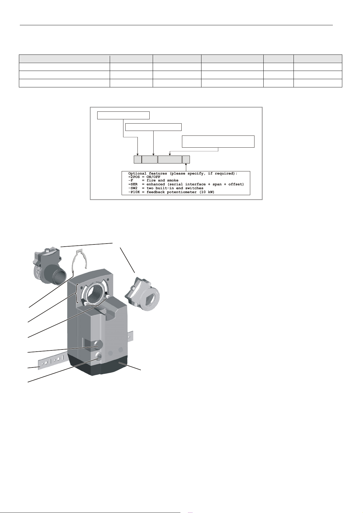
Product Identification System
N = non-spring return
S = spring return
20 = 20 Nm (177 lb-in)
34 = 34 Nm (300 lb-in)
010 = modulating
24 = 24 V floating+ON/OFF
230 = 230 V floating+ON/OFF
SmartAct
OPERATION / FUNCTIONS
1
60
90
90
60
30
0
2
3
4
5
6
7
Fig. 2. Setting units and control elements
30
0
N
0
2
Fig. 1. Product Identification System
X
320
Legend for Fig. 2:
1 Self-centering shaft adapter
2 Retainer clip
3 Rotational angle scales (0...90° / 90...0°)
4 Mechanical end limits (20 Nm [177 lb-in] models, only)
5 Declutch button
6 Anti-rotation bracket
7 Rotation direction switch
8 Access cover
Contents of Package
The delivery package includes the actuator itself, parts 1
through 8 (see Fig. 2), the anti-rotation bracket screws, and
the SM mounting plate and screws.
Modulating Control
The actuator is capable of being operated by several
controllers providing Vdc or mA output.
Rotary Movement
8
The control signal and the corresponding rotation direction
(clockwise or counterclockwise) can be selected using the
rotation direction switch (see part 7 in Fig. 2), thus eliminating
the need to re-wire. To ensure tight closing of the dampers,
the actuator has a total rotation stroke of 95°.
As soon as operating power is applied, the actuator may start
to run. When power is removed, the actuator remains in
position. For actuator-controller wiring instructions, see
section "Wiring" on page 5.
EN0B-0341GE51 R0409 2
Page 3
SmartAct N20010, N34010
Rotation Direction Switch
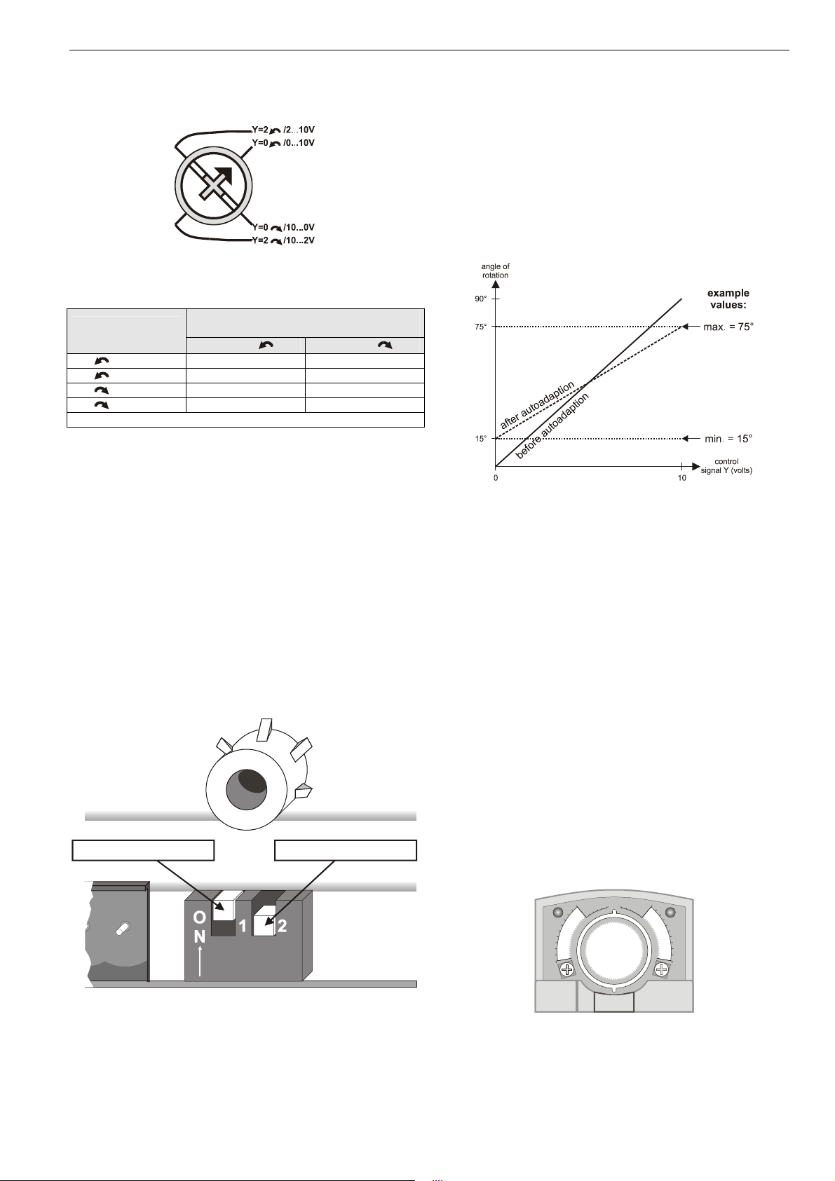
Fig. 3. Rotation Direction Switch
Table 1. Feedback/control signal values
rotation direction
switch position
feedback/control signal when
actuator is
totally totally
Y=2 /2...10V U = 2 V U = 10 V
Y=0 /0...10V* U = 0 V U = 10 V
Y=0 /10...0V U = 10 V U = 0 V
Y=2 /10...2V U = 10 V U = 2 V
* Default shipping position.
Feedback Signal and Manual Adjustment
If, while the actuator is not rotating, the user declutches it and
manually repositions the shaft adapter, the feedback signal
will then follow the new position at which the shaft adapter
has been left.
Power OFF/ON Behavior
In case the power to the actuator fails, after re-applying
power, the actuator aknowledges its present position and
follows the signal from the controller. This makes it
unnecessary for the actuator to employ autoadaption in order
to re-map the control signal settings.
Dip Switches
The actuators are equipped with two dip switches accessible
after removing the access cover (see Fig. 4).
autoadapt dip switch for
normal operation ( )
ON
voltage/current control signal
dip switch ( )
OFF
Autoadapt Dip Switch for Normal Operation
In its default shipping position, the autoadapt dip switch for
normal operation is set to ON as shown in Fig. 4. If it is set to
OFF, no autoadapting is performed, and the control signal
map remains constant.
The autoadapt functionality does not have to be triggered.
Rather, the SmartAct actuator does this automatically when
the min. and max. control signals are provided (see Fig. 5);
the feedback signal is likewise autoadapted.
Fig. 5. Actuator positioning curve
Adjusting the Actuator for Autoadapt
In order to make use of the autoadapt functionality, proceed
as follows:
1. Set the autoadapt dip switch to the ON position.
2. If necessary, limit the stroke to the desired range using
the mechanical end limits.
3. Drive the actuator to the left end limit (totally counterclockwise) by setting the control signal as specified in
Table 1.
4. Drive the actuator to the right end limit (totally clockwise)
by setting the control signal as specified in Table 1. The
stroke has now been limited to 0...100% of the control
signal range.
Voltage/Current Control Signal Selection Dip Switch
In its default shipping position, the voltage/current control
signal dip switch (see Fig. 4) is set to OFF (= voltage control).
as shown in Fig. 4. Setting it to ON results in current control.
Position Indication
The hub adapter indicates the rotation angle position by
means of the rotational angle scales (0...90° / 90...0°).
90 90
60
30
60
30
00
Fig. 4. Dip switches (view with PCB at bottom)
3 EN0B-0341GE51 R0409
Fig. 6. Position indication
Page 4

SmartAct N20010, N34010
85°80
5°90°0°92.5°5°10°15
Manual Adjustment
IMPORTANT
In order to prevent equipment damage, you must
remove power before manual adjustment.
After removing power, the gear train can be disengaged using
the declutch button, permitting the actuator shaft to be
manually rotated to any position. The feedback signal will
then follow the new position.
Limitation of Rotation Stroke
Two mechanical end limits (adjustable in 3° increments) are
provided (20 Nm [177 lb-in] models, only) to limit the angle of
rotation as desired (see Fig. 7).
ENSURE
PROPER
MESHING
OF TEETH
Fig. 7. Mechanical end limits
The mechanical end limits must be securely fastened in place
as shown in Fig. 8. Specifically, it is important that they
properly mesh with the rotational angle scales when the
screws are tightened.
CORRECT INCORRECT
CORRECT INCORRECT
Fig. 8. Correct / incorrect tightening of end limits
Internal End Switches
NOTE: Only those actuators for which the option "-SW2"
has been specified when ordering (e.g.: "N20010SW2") feature internal end switches.
The internal end switches are set to change from "common"
to "normally open" at angles of 5° and 85°, respectively, from
the totally counterclockwise position.
actuator scale: clockwise
5° 10° 15° 92.5°0° 90°-2.5° 85°80°75°
CCW internal
end switch
5° 10° 15°0° 90°85°80°75°
end switch scale
actuator scale: counterclockwise
°75°-2.
°
CW internal
end switch
Fig. 9. Internal end switches
Override
If terminal Y of the terminal strip (see section "Wiring
Diagrams" on page 6) is unplugged, the stroke will be 0%;
reversing the rotation direction using the rotation direction
switch will result in a max. stroke of 100%. If terminal Y is
jumped with terminal 1 (24 Vac), the stroke will be 50%.
EN0B-0341GE51 R0409 4
Page 5

SmartAct N20010, N34010
INSTALLATION
These actuators are designed for single-point mounting.
IMPORTANT
In order to prevent equipment damage, you must
remove power or set the rotation direction switch to the
"Service/Off" position before manual operation.
Mounting Instructions
All information and steps are included in the Installation
Instructions supplied with the actuator.
Mounting Position
The actuators can be mounted in any desired orientation (no
IP54 if mounted upside down; see Fig. 10). Choose an
orientation permitting easy access to the actuator's cables
and controls.
IP54 IP54IP54 IP54
Fig. 10. Mounting for IP54
Mounting Bracket and Screws
If the actuator is to be mounted directly on a damper shaft,
use the mounting bracket and screws included in the delivery
package.
Self-Centering Shaft Adapter
The self-centering shaft adapter can be used for shafts
having various diameters (10...27 mm [3/8...1-1/16"]) and
shapes (square or round).
In the case of short shafts, the shaft adapter may be reversed
and mounted on the duct side.
Stroke Limitation with Mechanical End Limits
The mechanical end limits (20 Nm [177 lb-in] models, only)
enable the stroke to be limited from 0...90° in increments of
3°.
5 EN0B-0341GE51 R0409
Page 6

SmartAct N20010, N34010
Wiring Diagrams
N20010 / N34010
TERMINAL STRIP 1
24 Vac 24 Vdc
~
0(2)...10 Vdc
0(4)...20 mA
0(2)...10 Vdc
Connect via safety
!
isolating transformer!
2
3Y
4U
1
1~
2
3Y
4U
MODULATING CONTROL
N20010-SW2
24 Vac 24 Vdc
~
TERMINAL STRIP 1
END SWITCHES
0(2)...10 Vdc
0(4)...20 mA
0(2)...10 Vdc
Connect via safety
!
isolating transformer!
MODULATING CONTROL
NOTE: Internal end switches S1 and S4 must be connected to the same power source.
connecting cable terminal name
supply and signal lines
(must be equipped with spark suppressors)
CCW (left) 5°
end switches
(when included)
CW (right) 85°
2
3Y
4U
1
1~
2
3Y
4U
S1
S1
S2
S2
S3
S3
S4
S4
S5
S5
S6
S6
END SWITCHES
1~ 24 Vac ~ / 24 Vdc +
2⊥ 24 Vac ~ / 24 Vdc -
3Y 0(2)…10 Vdc / 0(4)…20 mA control signal
4U 0(2)…10 V feedback signal
S1 common
S2 normally closed
S3 normally open
S4 common
S5 normally closed
S6 normally open
EN0B-0341GE51 R0409 6
Page 7

Wiring
Connecting to the Power Supply
In order to comply with protection class II, the power source of
24 V actuators must be reliably separated from the network
power supply circuits as per DIN VDE 0106, part 101.
Access cover
To facilitate wiring the actuator to the controller, the access
cover can be detached from the actuator.
IMPORTANT
Remove power before detaching the access cover.
Once the access cover has been removed, please
take care to avoid damaging any of the parts now
accessible.
SmartAct N20010, N34010
S3
A
B
A
B
S6
S1
S2
0
90
C
S4
D
45
S5
90
0
C
D
The internal auxiliary switches are field-installable parts
providing two SPDT freely-adjustable switches.
Access Cover Kit
Order no.: WB20
For M20 outlets.
Contains:
• 1 access cover (with screw)
• 2 cable connectors
• 2 dust-protection caps
SPARE PARTS
Fig. 11. Access cover (N20010-SW2)
Depending upon the model, the access cover may have one
or two terminal strips, including a layout with a description for
each of the terminals.
Fig. 12. N20010-SW2 with access cover removed
OPTIONAL ACCESSORIES
The following optional accessories can be ordered separately.
Auxiliary Switch Kit
Order no.: SW2
Spare Parts Kit
Order no.: A7209.2071
The spare parts kit contains the following items:
• Anti-rotation bracket and screws
• SM Mounting plate and screws
• Access cover screw
• Plastic protective cap for protection standard IP54
• Mechanical end limit screw and retainer
Anti-Rotation Bracket Kit
Order no.: A7209.2073
The anti-rotation bracket kit can be ordered separately.
Contains:
• 10 anti-rotation brackets
• 20 screws
SM Mounting Plate Kit
Order no.: A7209.2072
The SM mounting plate kit can be ordered separately.
Contains:
• 10 SM mounting plates
• 20 screws
7 EN0B-0341GE51 R0409
Page 8

SmartAct N20010, N34010
DIMENSIONS
100 mm (3-15/16”)
shaft
adapter
adapter (reverse)
20.6 mm
(1-3/16”)
min. 60 mm (2-3/8”)
shaft
95°
60
90
48 mm
(1-7/8”)
223 mm (8-25/32”)
30
0
92 mm (3-5/8”)
1000 mm (39”)
132 mm (5-3/16”)
230 mm [+/- 0.5 mm] (9-1/16” [+/-1/64”])
20 mm (25/32”)
2 mm (5/64”)
13 mm (1/2”)
7 mm (9/32”)
5 mm (+0.05, -0.10 mm)
25/128” (+0.002, -0.004”)
anti-rotation bracket
Manufactured for and on behalf of the Environmental and Combustion Controls Division of Honeywell Technologies Sàrl, Rolle, Z.A. La Pièce 16, Switzerland by its Authorized Representative:
Automation and Control Solutions
Honeywell GmbH
Böblinger Strasse 17
71101 Schönaich / Germany
Phone: (49) 7031 63701
Fax: (49) 7031 637493
http://ecc.emea.honeywell.com
Subject to change without notice. Printed in Germany
EN0B-0341GE51 R0409
 Loading...