

Page 1
M6161, M6181, M6184, M6191, M6194
❑ M6161
❑ M6181
❑ M6184
❑ M6191
❑ M6194
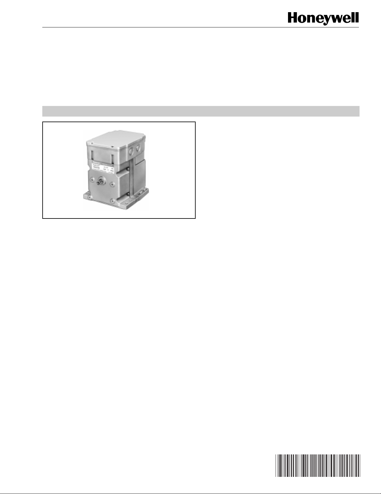
APPLICATION
These Modutrol IV Motors are 3-wire floating control motors
used with controllers that provide spdt or floating output to
operate dampers or valves.
Modutrol IV
FEATURES
• Replace M644 Motors.
• Oil immersed motor and gear train provides reliable
performance and long life.
• Wiring box provides NEMA 3 weather protection.
• Quick-connect terminals standard—screw terminal
adapter available.
• Adapter bracket for matching shaft height of older
motors is standard with replacement motors.
• Die-cast aluminum housing
• Integral auxiliary switches are available factory
mounted or can be field added to TRADELINE®
models.
Motors
SPECIFICATION DATA
™
® U.S. Registered Trademark
Copyright © 1996 Honeywell Inc. • All Rights Reserved
63-1156-2
Page 2

M6161, M6181, M6184, M6191, M6194 Modutrol IV™ MOTORS
SPECIFICATIONS
TRADELINE® Models
TRADELINE models are selected and packaged to provide
ease of stocking, ease of handling, and maximum
replacement value. TRADELINE model specifications are the
same as those of standard models, unless otherwise
specified. M6184D1035 and M6194D1017 are TRADELINE
models. TRADELINE models have auxiliary switch cams.
Standard Models
M6161A,B
M6181A,D,F
M6184A,B,D,F
M6191A,B,D
M6194A,B,D,E,F
NNNN
Control Type Suffix Letter
61 is Series 60 A: Fixed stroke
Power Rating No auxiliary switches
6 is low torque: B: Fixed stroke
35 lb-in. (90° or 160°),
8 is high torque: 1 auxiliary switch
150 lb-in. at standard D: Adjustable stroke
timing (60 sec for 160°) (90° to 160°),
9 is extra high torque: No auxiliary switches
300 lb-in. at 2 or 4 E: Adjustable stroke
minute timing (90° to 160°),
Output Drive 2 auxiliary switches
4 is dual-ended shaft, F: Adjustable stroke
non-spring return (90° to 160°),
1 is single-ended shaft, 2 auxiliary switches
non-spring return
NOTE: Some motors are furnished to HVAC equipment
manufacturers with no adapter bracket, a singleended shaft and/or no wiring box.
Electrical Ratings:
Voltage
M6161, M6181,
M6184, M6191, M6194
Without Transformer
(V at 50/
60 Hz)
a
With Internal
Transformer
a
Internal transformer can be field added.
Maximum Damper Rating:
Motor Torque lb-in. in. mm
75 48 1219
150 202 5131
300 258 6553
(90° or 160°),
Power
Current
Draw (A)
Consump-
tion (W)
24 0.69 15
120 0.21 20
208 0.12 20
240 0.11 20
B dim
Dead Weight Load on Shaft:
Power or Auxiliary End: 200 lb (90.8 kg) maximum.
Maximum Combined Load: 300 lb (136 kg).
Ambient Temperature Ratings:
Maximum: 150°F (66°C) at 25% duty cycle.
Minimum: Minus 40°F (-40°C).
Crankshaft: 3/8 in. (9.5 mm) Square.
M6184, M6194 have dual-ended shaft.
M6161, M6181, M6191 have single-ended shaft
Auxiliary Switch Ratings (Amperes):
One Contact Ratinga Amps 120V 240V
Full Load 7.2 3.6
Locked Rotor 43.2 21.6
a
40 VA pilot duty, 120/240 Vac on opposite contact.
Controller Type:
Floating 3-wire (Series 60)—drive open, hold, drive closed.
Stroke:
Fixed stroke models available with 90° or 160° stroke. Other
models available with stroke field adjustable from 90° to 160°.
Start position of shaft changes with adjustment of stroke.
(Midpoint of stroke remains fixed as stroke is adjusted.)
Stroke is adjusted using cams located in wiring compartment.
Dimensions:
See Fig. 1.
Underwriters Laboratories Inc. Listed:
File No. E4436, Guide No. XAPX.
Canadian Standards Association Certified:
General Listing File No. LR1620, Guide No. 400-E.
Timing and Torque:
NOTE: Motors with 2 minute timing at 90° stroke or 4 minute
timing at 160° stroke contain on-off pulsing circuitry
to achieve timing. Intermittent operation is normal.
Timing Torque in lb.-in (N•m)
90° Stroke
Motors
160° Stroke
Motors
Normal
Running Breakaway
a
30 sec 60 sec 35 (40) 70 (7.9)
15 sec 30 sec 75 (8.5) 150 (17.0)
30 sec 1 min 150 (17.0) 300 (34.0)
1, 2 min
a
Breakaway torque is the maximum torque available to
b
2, 4 minb300 (34.0) 600 (68.0)
overcome occasional large loads such as a seized damper
or valve.
b
Stalling of 4 minute motor may damage drive shaft.
Motor must not be used continuously at this rating.
63-1156—2
2
Page 3

M6161, M6181, M6184, M6191, M6194 Modutrol IV™ MOTORS
Accessories:
ES650117 Explosion-proof Housing: Encloses motor for
use in explosive atmospheres. Not for use with Q601,
Q618, and Q455 Linkages. Order separately from
Nelson Electric Co. Requires Honeywell 7617DM
Coupling.
Q607 External Auxiliary Switch: Controls auxiliary
equipment as a function of motor position.
Internal Auxiliary Switch Kits: Can be field-installed on
TRADELINE models.
220736A—One-switch Kit.
220736B—Two-switch Kit.
Q605 Damper Linkage: Connects motor to damper.
Includes motor crank arm.
Q618 Linkage: Connects Modutrol motor to water or steam
valve.
Q601 Bracket and Linkage Assembly: Connects Modutrol
motor to water or steam valve.
Q100A,B Linkage: Connects Modutrol motor to butterfly
valve.
Q68 Dual Control Potentiometer: Controls 1 through 9
additional motors.
4-7/8
(124)
5-1/2
(140)
Q181 Auxiliary Potentiometer: Controls 1 or 2 additional
motors.
221455A Infinitely Adjustable Crank Arm: Approximately
0.75 in. (19 mm) shorter than the 4074ELY Crank Arm.
Can rotate through downward position and clear base
of motor without requiring use of adapter bracket.
7617ADW Adjustable Crank Arm: Approximately 0.75 in.
(19 mm) shorter than the 7616BR Crank Arm. Can
rotate through downward position and clear base of
motor without requiring use of adapter bracket.
220741A Screw Terminal Adapter: Converts the standard
quick-connect terminals to screw terminals.
Transformers: Mounted internally, provide 24 Vac power to
motor.
198162JA—24 Vac; 50/60 Hz (for electrical
isolation).
198162EA—120 Vac; 50/60 Hz.
198162GA—220 Vac; 50/60 Hz.
198162AA—120/208/240 Vac; 50/60 Hz.
TOP VIEW OF 220738A BRACKET ONLY
4-7/32
(107)
3-15/16
(100)
2-5/16
(58)
5-13/16
(148)
7/16
WIRING
BOX
BASE
MOTOR
AUXILARY
END
ADAPTER
BRACKET
9/32
(7)
19/32 (15)
15/16
(24)
1/2
(13)
4-1/16 (103)
1-1/2 (38)
7-5/16 (185)
13/16
(20)
1-15/32 (37)
2-13/32 (61)
3/4 (19)
POWER
END
2-19/32
(66)
5-13/32
(137)
3/4
(19)
5/8
(16)
6-7/16
(164)
(11)
POWER END
9/32 (7)
4-7/8 (124)
5-17/32 (141)
1-1/4 (32)
2-1/2 (64)
21/32
(17)
Fig. 1. Dimensions in in. (mm). Note: M6161, M6181, M6191 models do not have auxiliary shaft.
All other dimensions are the same.
5/32
(4)
1-3/4
(44)
M302G
3
63-1156—2
Page 4

M6161, M6181, M6184, M6191, M6194 Modutrol IV™ MOTORS
Home and Building Control
Honeywell Inc.
Honeywell Plaza
P.O. Box 524
Minneapolis MN 55408-0524
Home and Building Control
Honeywell Limited-Honeywell Limitée
155 Gordon Baker Road
North York, Ontario
M2H 2C9
Honeywell Asia Pacific Inc.
Room 3213-3225
Sun Hung Kai Centre
No. 30 Harbour Road
Wanchai
Hong Kong
Honeywell Latin American Division
Miami Lakes Headquarters
14505 Commerce Way Suite 500
Honeywell Europe S.A.
3 Avenue du Bourget
B-1140 Brussels Belgium
Miami Lakes FL 33016
By using this Honeywell literature, you agree that Honeywell will have no liability for any damages arising out of your use or modification to, the literature. You will defend and
indemnify Honeywell, its affiliates and subsidiaries, from and against any liability, cost, or damages, including attorneys’ fees, arising out of, or resulting from, any modification to the
literature by you.
Helping You Control Your World
63-1156—2
63-1156—2 G.R. Rev. 5-96
Printed in U.S.A. on recycled paper
containing at least 10% post-consumer paper fibers
4
 Loading...