

Page 1
M436A/M836A,B Damper Motors
INSTALLATION INSTRUCTIONS
FEATURES
• Motors provide two-position zone control.
• Used to operate outdoor air dampers for combustion
or makeup air, changeover dampers for heating and
cooling systems, minimum position dampers for
ventilation and similar applications.
• Damper motors have an internal spdt switch for
controlling auxiliary equipment, additional motors, or
to provide a burner interlock switch.
• M436 Damper Motors require 120 or 240 Vac, 60 Hz
power; M836 Damper Motors require 24 Vac, 60 Hz
power.
• All models are supplied with a case and cover.
• Spring returns motor to start position in event of
power interruption or failure.
• Hexagonal output shafts on both ends of motor with
rotational direction stamped on motor case.
• M436A and M836A equipped with thermal breaker for
APPLICATION
M436A/M836A,B Damper Motors are spring return (SR)
motors used for residential and light commercial applications
in Series 40 and Series 80 circuits.
A 2-wire, line voltage thermostat or other line voltage, spst
controller must be used to control the M436A. A 24V spst
controller or thermostat without heat anticipation is required to
operate the M836A. The M836B requires 24V thermostat with
a 0.75 A heat anticipator adjustment.
Each damper motor is supplied with a shaft coupling assembly
and a crank arm assembly. With these accessories the motor
shaft may be connected to the damper shaft directly or
through a linkage.
overload protection during lifting stroke or when motor
stalls.
• M836A Damper Motor with 128499 Bracket directly
replaces M87A Damper Motor.
• These damper motors operate:
— Outdoor air dampers for combustion air in boiler
rooms.
— Backdraft dampers for exhaust fans.
— Outdoor air inlet dampers for industrial makeup air
units.
— Changeover dampers for heating and cooling sys-
tems.
— Minimum position damper for ventilation from outdoor
air.
— Two-position zone control dampers.
— Both motor types have an adjustable auxiliary switch
(spdt) for operating auxiliary equipment or cascading
motors, or to act as a burner interlock switch.
60-2119-05
Page 2
M436A/M836A,B DAMPER MOTORS
SPECIFICATIONS
IMPORTANT
The specifications given in this publication do not
include normal manufacturing tolerances. Therefore,
an individual unit may not exactly match the listed
specifications. Also, this product is tested and calibrated under closely controlled conditions and some
minor differences in performance can be expected if
those conditions are changed.
TRADELINE® Models:
TRADELINE® models are selected and packaged to provide
ease of stocking, ease of handling, and maximum replacement value. TRADELINE® model specifications are the
same as those of the standard models except as noted
below.
TRADELINE® Models Available:
M436A Damper Motor: 120 or 240 Vac, 60 Hz.
M836A,B Damper Motors: 24 Vac, 60 Hz.
Accessories: See Table 1. Crank arm, mounting bracket
#198545, and shaft coupling bag assemblies are included
with motors; brackets listed in Table 1 must be ordered
separately.
Table 1. Accessories Available
Type Bag Assembly
Bag Assembly
Part Number
Bracket
Included
Bracket
Height
Bracket 16254AC 128499 2.25 in.
Bracket - Mounting 7640JM 126809 N/A
Bracket 7640JN 126336 0.5 in.
Crank Arm 7640JL N/A N/A
Shaft Coupling 7640JE N/A N/A
Bracket 198545 198545 2.25 in.
Additional Features:
TRADELINE® pack with cross reference label and instruction
sheet.
Standard Models (See Table 2):
M436A Damper Motor: 120 or 240 Vac spring return motor for
use with two-wire thermostats or other spst controllers.
Includes internal adjustable spdt switch for controlling auxiliary equipment.
M836A Damper Motor: 24 Vac spring return motor for use with
spst controllers without heat anticipation. Includes internal
adjustable spdt switch for controlling auxiliary equipment.
M836B Damper Motor: 24 Vac spring return motor for use with
spst controllers. If circuit has thermostat heat anticipation,
set the anticipator at 0.75A. Includes internal adjustable
spdt switch for controlling auxiliary equipment.
Table 2. M436/M836 standard models.
Nominal Current
Model
Number
Voltage
(Vac)
(amperes)
M436A 120 0.37 0.12 27.0 8.5 20 30 30
240 0.19 0.06 27.0 8.5
M836A 24 1.85 0.6 27.0 8.5 20 30 30
M836B 24 1.34 0.73 20.3 11.2 15 30 25
a
Breakaway torque is available to overcome an occasionally frozen or seized damper or valve. The motor must not be used
Nominal Power
(watts)
Maximum
Load Torque
(lb-in.)
Breakawa
y Torque
(lb-in.)
Opening
a
Time
(nominal)
(nominal)
(nominal)
(sec)
b
Closing
b
Time
(sec)
25
(nominal)
25
(nominal)
25
(nominal)
Damper
Blade Area
(sq ft)Opening Holding Opening Holding
13
13
10
continuously at this rating.
b
40 sec maximum.
Ambient Temperature Rating: 32° to 125°F (0° to 52°C).
Finish: Gray.
Table 3. Auxiliary switch ratings (in amperes).
Power 120 Vac 240 Vac
Dimensions: See Fig. 1.
Approvals:
Full Load 7.2 3.6
Locked Rotor 43.2 21.6
Underwriters Laboratories Inc. Listed (M436A, M836A):
File No. E4436, Guide No. XAPX.
Auxiliary Switch Action:
Spdt, normally open (R-B) contacts close during the power
Auxiliary Switch Ratings (In Amperes): See Table 3.
Pilot Duty: 40 VA at 120 or 240 Vac.
stroke and open during the return stroke. Can be adjusted
to operate at any point between 5 and 70 degrees of motor
stroke.
60-2119—05 2
Page 3
M436A/M836A,B DAMPER MOTORS
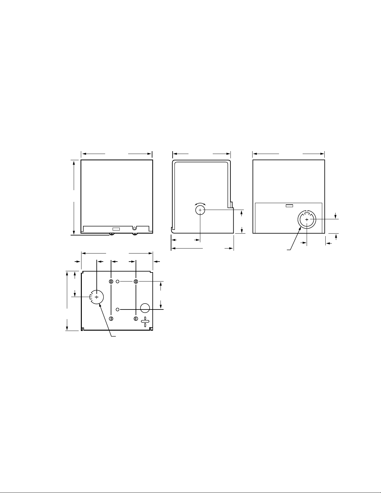
1
(25)
1-1/2
(38)
4-5/8 (118)
4-5/8 (118) 4-5/8 (118)
1-5/8 (42)
1-5/8
(42)
3-3/4
(96)
3-17/32 (90)
25/32
(20)
29/32 (23)
3-3/4 (96)
1-3/4
(45)
1-3/8
(35)
4-1/2
(115)
1-1/8
(29)
COMBINATION
KNOCKOUT FOR
1/2 INCH AND
3/4 INCH CONDUIT
KNOCKOUT FOR 1/2 INCH CONDUIT
M9950
OPEN CLOSE
Angular Stroke: 75 degrees.
Weight: 4 lb, 10 oz (2.1 kg).
Optional Specifications:
M436 with crank arm.
M436A Damper Motor, 50 Hz for international applications.
Models for 220 or 240 Vac, with 50 second opening stroke,
25 second closing stroke. Includes ground and cover
screws and 7640JL Bag Assembly.
M836A Damper Motor, 50 Hz for international applications.
Model is for 24 Vac, with 50 second opening stroke and 25
second closing stroke. Includes ground and cover screws
and 7640JL Bag Assembly.
Accessories:
16254AC Bag Assembly, includes 128499 Mounting Bracket
and screws (see Fig. 2 and 6).
7640JE Bag Assembly, includes drive bushings, adapter, and
coupling for direct drive (see Fig. 4 and 7).
7640JL Bag Assembly, includes clamp and crank arm lever
for crank arm drive (see Fig. 5 and 6).
7640JM Bag Assembly, includes 126809 Mounting Bracket
and screws (see Fig. 3, 4 and 7).
7640JN Bag Assembly, includes 128336 Mounting Bracket
and screws (see Fig. 2 and 6).
4074BRU Bag Assembly, includes extension adapter and
screws for mounting Q607 Auxiliary Switch to M436A
Damper Motor.
Q298B Linkage, includes damper crank arms, bushings, 1/4
in. (6.5 mm) and ball joint assemblies (see Fig. 6).
Fig. 1. M436 and M836 Damper Motors dimensions in in. (mm).
3 60-2119—05
Page 4

M436A/M836A,B DAMPER MOTORS
CAUTION
4-3/16
(106)
3-9/16
(91)
1-31/64
(38)
2-3/32
(53)
11/32
(9)
1/2
(13)
3-5/8 (92)
M9944
5/16
(8)
1-3/4 (45)
2-11/32 (60)
19/32
(15)
13/64 (5) DIAMETER (2)
13/64 (5) DIAMETER
3-3/4 (96) 1-7/16
(37)
3-3/4
(95)
1-3/8
(35)
2-1/16
(52)
2-1/8
(54)
3-5/8 (92)
2-11/32 (60)
2-11/32
(60)
3-3/4
(95)
4-1/4
(108)
M16866
M9949
CLEARANCE HOLES FOR
MOUNTING SCREWS (4)
1-3/4
(46)
19/64 (8)
DIAMETER (2)
1-1/4 (32)
DIAMETER
7/16 (11)
CLEARANCE
HOLES (10)
2-3/8
(61)
4-23/32 (120)
2-3/8
(61)
1-3/16
(30)
2-35/64
(65)
1-1/2 (38) 1-3/8 (35)2-13/64 (61)
Fig. 4. 126809 Bracket dimensions in in. (mm).
INSTALLATION
Fig. 2. 128336, 128499 Mounting Brackets dimensions in
Fig. 3. 198545 Bracket dimensions in in. (mm).
60-2119—05 4
in. (mm).
When Installing this Product...
1. Read these instructions carefully. Failure to follow them
could damage the product or cause a hazardous condition.
2. Check the ratings and descriptions given on the product
to make sure the product is suitable for your application.
3. Installer must be a trained, experienced service techni-
cian.
4. After installation is complete, check out productopera-
tion as provided in this specification.
Electrical Shock Hazard.
Can cause severe injury, death or property
damage.
1. Disconnect power supply before installation to
prevent electrical shock or equipment damage.
2. To prevent damage to the gear train, never turn the
motor shaft by hand or with a wrench.
3. Do not install the actuator in areas with acid fumes
or other deteriorating vapors that might attack the
metal parts of the motor.
4. Do not install the actuator in areas with escaping
gas or other explosive vapors that could be ignited
by a spark from the actuator or attached
accessories.
Location and Mounting
IMPORTANT
Mount M436 and M836 Damper Motors with the
shaft in the horizontal position.
Install the motor in a location where the ambient temperature
range is within 32° to 125°F, free from acid fumes or other
deteriorating vapors that might attack the metal parts of the
Page 5

motor. Also, make sure the location is free from escaping gas
M9946
BUSHING FOR
1/4 INCH (6.5 mm)
DAMPER SHAFT
BUSHING FOR
3/8 INCH (9.5 mm)
DAMPER SHAFT
CLAMP
ADAPTER
FOR
DAMPER
COUPLING
OPEN CLOSE
126809
BRACKET
M9945
1
1 CLAMP AND CRANKARM LEVER ARE DESIGNED TO FIT TIGHTLY
TOGETHER. IF NECESSARY, TAP THESE PARTS TOGETHER
PRIOR TO MOUNTING ON MOTOR TO ENSURE TIGHTNESS.
CRANKARM
LEVER
CLAMP
OPEN CLOSE
M9941
BRACKET
126809
BRACKET 128336
OR 128499
7640JL CRANK
ARM ASSEMBLY
Q298B
LINKAGE
1
1 ASSEMBLE 7640JL CRANK ARM ASSEMBLY TO MOTOR
AND Q298B LINKAGE TO DAMPER. ADJUST LENGTH
OF STEEL ROD AS NECESSARY. ONE Q298B CRANK
ARM IS NOT NECESSARY AND MAY BE DISCARDED.
or other explosive vapors that could be accidentally ignited by
a spark from the motor or its attached parts.
Install the motor in a location that allows enough clearance for
mounting accessories and for servicing.
Locate as near as possible to the equipment to be controlled.
The 198545 Mounting Bracket and 7640JE Bag Assembly are
for direct coupling to the damper shaft from either end of the
motor, depending upon the desired rotational direction.
The 198545 Mounting Bracket may also be used for offset
mounting with the 7640JL Bag Assembly and a standard
damper linkage, such as Q605. 128336 Mounting Bracket
must be used with 7640JL Bag Assembly and a standard
damper linkage.
Mounting brackets and crankarm drives are furnished with
TRADELINE® models of these motors or can be ordered
separately if required for the installation. Refer to the
Accessories section for specifications, Fig. 2 and 4 for
dimensions, and Fig. 5 through 8 for installation drawings.
M436A/M836A,B DAMPER MOTORS
Fig. 5. Exploded view showing how to mount 7640JE
Damper Shaft Coupling and 7640JM Mounting Bracket
Assembly to motor.
Fig. 6. Exploded view showing how to mount 7640JL
Crankarm Assembly to motor.
Fig. 7. Offset mounting with 7640JL Crankarm Assembly
and Q298B Linkage.
5 60-2119—05
Page 6

M436A/M836A,B DAMPER MOTORS
CAUTION
CAUTION
M9940
BRACKET 126809
(7640JM ASSEMBLY)
M9942
1
L1
L2
B
W
R
2
1
2
PROVIDE DISCONNECT MEANS AND
OVERLOAD PROTECTION AS REQUIRED.
MAKES R TO B DURING MOTOR POWER (OPEN) STROKE.
L2
LINE VOLTAGE
TWO POSITION
CONTROLLER
TO
AUXILIARY
EQUIPMENT
L1
(HOT)
AUXILIARY
SWITCH
M436A
TO POWER SUPPLY
M9948
1
L1
L2
B
W
R
2
1
2
PROVIDE DISCONNECT MEANS AND
OVERLOAD PROTECTION AS REQUIRED.
MAKES R TO B DURING MOTOR POWER (OPEN) STROKE.
L2
LOW VOLTAGE
TWO POSITION
CONTROLLER
TO
AUXILIARY
EQUIPMENT
L1
(HOT)
AUXILIARY
SWITCH
M836A
TO POWER SUPPLY
24 VOLT
TRANSFORMER
Fig. 8. Damper motor directly coupled to damper using
7640JM Mounting Bracket Assembly and 7640JE Drive
Coupling Assembly.
Wiring
Electrical Shock Hazard.
Disconnect the power supply before wiring to prevent
electrical shock or equipment damage.
Disconnect the power supply before beginning wiring to
prevent electrical shock or equipment damage. All wiring must
comply with local electrical codes, ordinances and
regulations. Refer to Fig. 9 and 10 for typical hookup
diagrams and to information furnished with the system
equipment.
Fig. 10. Typical wiring diagram for M836 Damper Motor.
ADJUSTMENT AND CHECKOUT
Auxiliary Switch Adjustment
Adjust the internal spdt auxiliary switch of the M436/M836
Damper Motor to operate at any point between 5 degrees and
70 degrees of the motor stroke. The switch has a 1 to 2
degree nonadjustable differential. The switch makes R to B
contact during the power stroke (motor shaft moves in the
direction of the OPEN arrow on the outside of the case).
Apply power to the motor so that the motor runs to the OPEN
position. Note the point of the motor stroke where the switch
operates (audible click or check for continuity across the R to
B terminals) If the switch operates correctly for the application,
proceed to check out the installation. If the switch needs to be
adjusted, perform the following steps:
1. Determine the number of degrees that the switch cam
must be adjusted to operate the switch at the desired
point of the motor stroke.
IMPORTANT
Do not adjust switch to operate closer than five
degrees from the ends of the motor stroke.
Fig. 9. Typical wiring diagram for M436 Damper Motor.
60-2119—05 6
2. Remove the motor cover.
Electrical Shock Hazard.
To prevent electrical shock or equipment damage,
disconnect the power supply before adjusting the
switch cam.
Page 7

M436A/M836A,B DAMPER MOTORS
OPEN CLOSE
M9947
M9951
OIL
HERE
OIL
HERE
(FELT
PAD)
OIL
HERE
OIL
HERE
3. Insert a narrow bladed common-point screwdriver in a
slot in the switch cam (white plastic) located near the
center of the motor. Refer to Fig. 10. Each slot in the
cam equals approximately 20 degrees of motor rotation.
4. Select a reference point and move the cam the correct
number of degrees, as follows:
a. To adjust the switch to operate nearer the open
(maximum rotation) motor position, move the cam in
the direction of the CLOSE arrow on the outside of
the motor case.
b. To adjust the switch to operate nearer the closed
motor position, move the cam in the direction of the
OPEN arrow on the outside of the motor case.
Repower the motor and check the point at which the switch
makes and breaks. Readjust as necessary.
and that the motor travels smoothly through the fully open and
fully closed positions. Cut any excess linkage rod length to the
correct size.
Make necessary minor adjustments until desired operation is
obtained and tighten all nuts and setscrews. A motor checkout
should prove that:
1. The motor operates the load.
2. The motor responds properly to the controller.
3. There is no linkage binding or motor stalling at any point
of travel.
If the motor does not operate properly, check for proper
voltage or mechanical linkage or damper binding.
Lubrication
To assure long motor life, annually lubricate the felt pads
located on each of the motor bearings and on the two shafts in
the gear train. See Fig. 11. Use Anderol® 465 Oil or an
equivalent. Light sewing machine oil is an acceptable
equivalent. Do not over lubricate. One drop at each lubrication
point is sufficient.
Fig. 11. Using screwdriver to adjust auxiliary switch cam.
Checkout
Operate the motor through the complete open-close stroke.
Be prepared to release one of the previously tightened linkage
connections, if necessary, to prevent damage. Check for
proper operation, making sure that the linkage does not bind
Fig. 12. M436/M836 Damper Motor lubrication points.
7 60-2119—05
Page 8

M436A/M836A,B DAMPER MOTORS
Automation and Control Solutions
Honeywell International Inc.
1985 Douglas Drive North
Golden Valley, MN 55422
Honeywell Limited-Honeywell Limitée
35 Dynamic Drive
Toronto, Ontario M1V 4Z9
customer.honeywell.com
® U.S. Registered Trademark
© 2010 Honeywell International Inc.
60-2119—05 M.S. Rev. 10-10
Printed in U.S.A.
 Loading...