

Honeywell L482A Installation Guide
L482A
Low Limit Controller
INSTALLATION INSTRUCTIONS
BEFORE INSTALLATION
No special tools are required to install the L482A Low Limit
Controller. Refer to the job drawings for specific wiring and
installation information.
INSTALLATION
When Installing this Product...
1. Read these instructions carefully. Failure to follow them
could damage the product or cause a hazardous
condition.
2. Check ratings given in instructions and on the product to
ensure the product is suitable for your application.
3. Installer must be a trained, experienced service
technician.
4. After installation is complete, check out product
operation as provided in these instructions.
Mounting
IMPORTANT
1. The controller operates from the lowest temperature
along the entire 20 feet of the sensing element.
2. Locate controller case and bellows where ambient
temperature is always warmer than the set point.
3. For settings above the scale range midpoint it can be
necessary to locate the controller case close to a
steam pipe or other warm surface and make sure the
element does not extend across a cold surface.
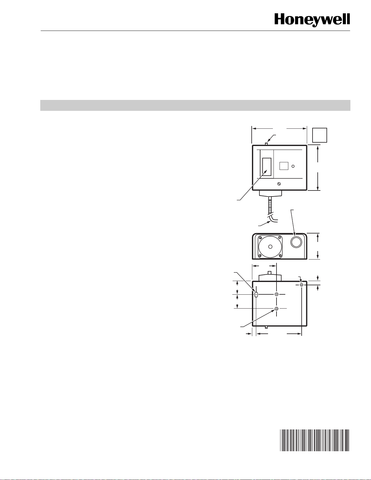
Controller
Surface mount the controller (Fig. 1) vertically on any
convenient location (including the duct itself). Orient the case
with the bellows positioned on the bottom.
SETPOINT
SCALE
20 FT BY 1/8 INCH
SENSING ELEMENT
3/8 X 3/16
(10 X 5)
DIAMETER
ELONGATED
MOUNTING
HOLE
1-1/8 (29)
1 (25)
MOUNTING
HOLES (2)
10-32 UNF-2B
THREAD
5/16 (8)
1-7/8
(48)
4 (101)
SETPOINT
ADJUSTMENT
SCREW
3-1/4 (83)
7/8 (22) HOLE
FOR 1/2 CONDUIT
WITH 1-3/32 (28)
KNOCKOUT RING
FOR 3/4 CONDUIT
3/16 (5)
DIAMETER
MOUNTING
HOLE
PUSH
TO
RESET
4-11/16
(119)
2-3/32
(53)
5/16
(8)
C606A
Fig. 1. L482A Low Limit Controller dimensions in in. (mm).
® U.S. Registered Trademark
Copyright © 2004 Honeywell International Inc.
All Rights Reserved
95-7432-1
996-496 Rev. A
L482A LOW LIMIT CONTROLLER
IF
Sensing Element
IMPORTANT
• The maximum allowable sensing element tempera-
ture is 250°F (121°C).
• Uncoil only the amount of element required for the
application.
• Bend element carefully and only as much as neces-
sary. Bends require a minimum radius of one inch
(25 mm).
• Bend only some distance from the controller.
• Pulling on the element damages it.
• For elements subject to vibration, provide protection
from any surface which the element contacts.
• Mount element horizontally as shown in Fig. 2 and 3.
1. Locate the sensing element where it can sense the
temperature of the air to be controlled.
NOTE: Locate the element away from hot or cold air
inlets.
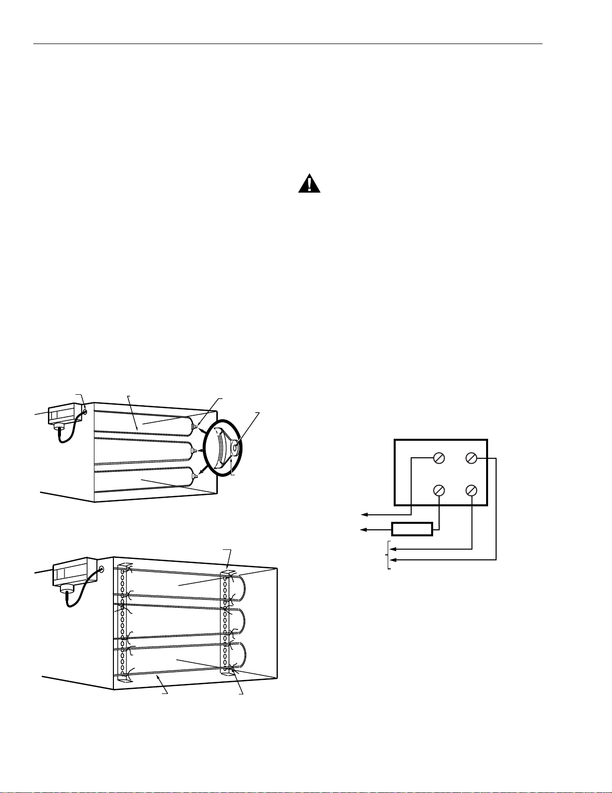
2. Punch or drill a 1/4 in. hole in the duct and install
CCT1802 Grommet (Fig. 2) to protect the capillary.
3. Carefully insert the element through the grommet into
the duct. Use as much element as possible to provide
maximum protection.
4. Mount the element inside the duct or fasten to the coil if
freezing can occur.
a. Duct mounting: Use CCT2600 Clip (Fig. 2).
b. Coil fastening: Use perforated metal straps (Fig. 3).
GROMMET
ELEMENT
USE NO. 10
SHEET METAL
SCREWS
OPERATION
On a temperature drop to setpoint, LINE 1 to M1 contacts
close and LINE 2 to M2 contacts open. Reset to the normal
state is manual.
WIRING
WARNING
Electrical Shock Hazard.
Can cause severe injury, death or equipment
damage.
Disconnect power supply before beginning installation
to prevent electrical shock or equipment damage.
IMPORTANT
– All wiring must agree with applicable codes,
ordinances and regulations.
– When switching both ac line voltage and an
automation input (Fig. 4), the input wires must
run no more than three feet in the same conduit.
See Fig. 6.
For typical L482A wiring, see Fig. 4 and 5.
NOTES:
– Screw terminals are provided for wiring
connections.
– Maximum wire size is 12 AWG.
– Use 8-32 x 1/4-inch screws for replacement if
necessary. Longer screws can interfere with the
switch mechanism and damage the switch.
CLIP
DETAIL
BEND HERE
NECESSARY
Fig. 2. Element mounted to duct with CCT2600 Clips.
PERFORATED METAL STRAPS
WIRE FASTENINGSELEMENT
Fig. 3. Element mounted in duct with
perforated metal straps.
C789
C790
LINE 2 LINE 1
M1
C791
L1
(HOT)
L2
TO STATUS
OR ALARM
INPUT OF
AUTOMATION
SYSTEM
M2
FAN RELAY
Fig. 4. Typical wiring diagram with automation input.
95-7432–1 2
996-496 Rev. A
 Loading...