

Page 1

Galaxy Dimension
Installer Manual
Honeywell Security
Page 2

Page 3

Galaxy Dimension Installer Manual
Table of Contents
Contents
INTRODUCTION ....................................................................................... 1-1
Variants ................................................................................................................1-1
SECTION 1: QUICK SETUP .................................................................... 1-3
SECTION 2: SYSTEM ARCHTECTURE .................................................. 2-1
PCB Layout .......................................................................................................... 2-2
RS485 Expansion Module (GD-520 only) .........................................................2-3
System Installation and Wiring .........................................................................2-4
Connecting the Galaxy Dimension to the PSTN.............................................. 2-5
Connecting Additional Telecom Apparatus .......................................................................... 2-6
Line Monitoring .................................................................................................................... 2-6
Stand-by Battery .................................................................................................2-7
Battery Start-up ..................................................................................................................... 2-7
On-Board Power Supply Unit.............................................................................2-7
Memory ................................................................................................................2-8
RS485 Data Communication Bus (AB Lines) ................................................... 2-8
RS485 Wiring Configurations ............................................................................ 2-8
RS485 Wiring Recommendations .....................................................................2-9
Zones ................................................................................................................. 2-11
Zone Addresses ................................................................................................................ 2-11
Wiring Zones .....................................................................................................................2-13
Wiring Multiple Detectors ................................................................................2-15
Wiring Keyswitches ............................................................................................................ 2-15
Wiring Terminator Buttons ..................................................................................................2-16
Outputs ..............................................................................................................2-16
Output Applications ......................................................................................... 2-17
Trigger Header ..................................................................................................2-18
Trig 1-6 ............................................................................................................................... 2-18
Supply ................................................................................................................................2-18
SPI Header ......................................................................................................... 2-19
SECTION 3: PERIPHERALS ................................................................... 3-1
General................................................................................................................. 3-1
Wiring ................................................................................................................... 3-1
i
Page 4

Table of Contents
Galaxy Dimension Installer Manual
Configuring ......................................................................................................... 3-1
Addressing........................................................................................................................... 3-1
Connecting the RIO.............................................................................................................. 3-2
Configuring the RIO..............................................................................................................3-2
RIO Outputs.......................................................................................................................... 3-3
RF RIO .................................................................................................................. 3-4
Connecting the RF RIO ........................................................................................................ 3-4
Addressing the RF RIO ........................................................................................................ 3-5
RF RIO Programming ..........................................................................................................3-6
Configuring the RF RIO ........................................................................................................ 3-6
Power Supply Unit .............................................................................................. 3-7
Configuration ........................................................................................................................ 3-7
Installation Instructions ......................................................................................................... 3-8
Battery .................................................................................................................................. 3-9
Battery Test ........................................................................................................................... 3-9
Specifications ....................................................................................................................... 3-9
EN50131 Compliance ......................................................................................................... 3-9
Printer Interface Module ..................................................................................3-10
ISDN Module ...................................................................................................... 3-11
Programming the ISDN Module ......................................................................................... 3-11
Ethernet Module ...............................................................................................3-12
Configuring the Ethernet Module ....................................................................................... 3-12
Ethernet Communication ................................................................................................... 3-12
Galaxy Dimension and 2-Way Audio .............................................................. 3-13
Introduction.........................................................................................................................3-13
Audio Interface Module ......................................................................................................3-13
MUX Module ......................................................................................................................3-15
Remote Servicing Suite....................................................................................3-17
User Management Suite ................................................................................... 3-17
SECTION 4: KEYPADS ........................................................................... 4-1
The Galaxy Mk7 Keypad/KeyProx.....................................................................4-1
General ................................................................................................................................ 4-1
Power Consumption ............................................................................................................ 4-1
Wiring the Keypad/KeyProx ................................................................................................. 4-2
Keypad/KeyProx Installation Procedure............................................................................... 4-2
Self Diagnostics.................................................................................................................... 4-5
Keypad/KeyProx Operation ................................................................................................. 4-5
The Galaxy KeyProx ........................................................................................... 4-8
General ................................................................................................................................ 4-8
Addressing........................................................................................................................... 4-8
ii
Page 5

Galaxy Dimension Installer Manual
Operation ............................................................................................................................. 4-8
Card Types........................................................................................................................... 4-8
Table of Contents
The Galaxy Dimension TouchCenter................................................................4-9
General ................................................................................................................................ 4-9
TouchCenter Installation Procedure ..................................................................................... 4-9
Configuring a TouchCenter ................................................................................................ 4-10
Set-up Menu ......................................................................................................................4-10
TouchCenter - Operation ................................................................................................... 4-11
Specifications ..................................................................................................................... 4-11
SECTION 5: ACCESS CONTROL ........................................................... 5-1
Group Based Access Control............................................................................ 5-1
User and Access Templates .............................................................................. 5-1
Time Schedules .................................................................................................. 5-1
Door Control Module .......................................................................................... 5-2
MAX3 ....................................................................................................................5-7
SECTION 6: SYSTEM OPERATION ........................................................ 6-1
Menu Options...................................................................................................... 6-1
General ................................................................................................................................ 6-1
The Full Menu...................................................................................................................... 6-1
The Quick Menu .................................................................................................................. 6-1
Menu Access ....................................................................................................................... 6-1
Engineer Mode ....................................................................................................................6-2
Setting Options ................................................................................................... 6-5
Setting the System Using a PIN ............................................................................................ 6-5
Cancelling the Setting ..........................................................................................................6-5
Unsetting the System Using a PIN........................................................................................ 6-6
Engineer Unsetting ..............................................................................................................6-6
Keyswitch Setting Options .................................................................................................... 6-6
Setting the System with Cards/Tags/Fobs ............................................................................ 6-6
Cancelling and Resetting Alarms and Alerts ........................................................................ 6-7
Recording of Events ............................................................................................................. 6-7
Overriding of Faults and Tampers........................................................................................ 6-8
Setting Features ................................................................................................................... 6-8
Menu Options 11-19 ......................................................................................... 6-11
Option 11 – Omit Zones (Quick Menu Option 0) .............................................................. 6-11
Option 12 – Timed Set ....................................................................................................... 6-13
Option 13 – Part Set ...........................................................................................................6-13
Option 14 – Forced Set (Quick Menu Option 1) ................................................................6-13
Option 15 – Chime (Quick Menu Option 2) ....................................................................... 6-13
iii
Page 6

Table of Contents
Option 16 – Instant Set .......................................................................................................6-13
Option 17 – Silent Part .......................................................................................................6-14
Option 18 – Home Set ....................................................................................................... 6-14
Option 19 – All Set..............................................................................................................6-14
Galaxy Dimension Installer Manual
Display Options ................................................................................................ 6-15
Option 21 – Display Zones (Quick Menu Option 3) ........................................................... 6-15
Option 22 – Display Log (Quick Menu Option 4) ...............................................................6-16
Option 23 – System............................................................................................................6-17
Option 24 – Print (Quick Menu Option 5) ........................................................................... 6-18
Option 25 – Access Doors ................................................................................................. 6-19
Test Options ......................................................................................................6-23
Option 31 – Walk Test (Quick Menu Option 6)...................................................................6-23
Option 32 – Outputs ...........................................................................................................6-25
Modify Options ................................................................................................. 6-26
Option 41 – Time/Date (Quick Menu Option 7) ................................................................. 6-26
Option 42 – Codes (Quick Menu Option 8) .......................................................................6-27
Option 43 – Summer (Quick Menu Option 9) ....................................................................6-38
Option 44 – Trace ..............................................................................................................6-38
Option 45 – Timer Control .................................................................................................. 6-39
Option 46 – Group Omit ..................................................................................................... 6-43
Option 47 – Remote Access ..............................................................................................6-44
Option 48 – Engineer access ............................................................................................6-50
Engineer 1 .........................................................................................................6-51
Option 51 – Parameters.....................................................................................................6-51
Option 52 – Program Zones .............................................................................................. 6-71
Option 53 – Program Outputs ............................................................................................6-87
Option 54 – Links .............................................................................................................6-104
Option 55 – Soak .............................................................................................................6-107
Option 56 – Communications .......................................................................................... 6-108
Option 57 – System Print ..................................................................................................6-151
Option 58 – Keypad .........................................................................................................6-152
Option 59 – Quick Menu ..................................................................................................6-155
Engineer 2 .......................................................................................................6-156
Option 61 – Diagnostics...................................................................................................6-156
Option 62 – Full Test ........................................................................................................6-159
Option 63 – Options .........................................................................................................6-160
Option 64 – Assemble Zone............................................................................................6-164
Option 65 – Timers ..........................................................................................................6-168
Option 66 – Pre-checks ................................................................................................... 6-175
Option 67 – Remote Reset .............................................................................................. 6-176
Option 68 – Menu Access ............................................................................................... 6-177
Option 69 – Integrated Access Control ............................................................................6-178
iv
Page 7

Galaxy Dimension Installer Manual
Engineer 3 .......................................................................................................6-192
Option 71 – SPI Key .........................................................................................................6-192
Table of Contents
Appendix A: Library .............................................................................. A-1
Appendix B: SIA and Contact ID Event Codes .................................... B-1
Appendix C: SIA Event Structure ........................................................ C-1
Appendix D: Event Log Messages ....................................................... D-1
Appendix E: Site Data Storage..............................................................E-1
Preparing for Storage Mode ..............................................................................E-1
Enabling Storage Mode .....................................................................................E-1
Using Storage Mode ...........................................................................................E-2
Leaving Storage Mode .......................................................................................E-2
Appendix F: Specifications ................................................................... F-1
Panel Specifications........................................................................................... F-1
Appendix G: Declaration of Conformity .............................................. G-1
Compliance and Approvals .............................................................................. G-1
EN50131 Compliance......................................................................................... G-2
PD6662 Compliance........................................................................................... G-2
Public Switched Telephone Network (PSTN) approval.................................. G-2
Appendix H: Parts List Index................................................................ H-1
Index ..................................................................................................Index-1
v
Page 8

Table of Contents
Galaxy Dimension Installer Manual
vi
Page 9

Galaxy Dimension Installer Manual
Introduction
INTRODUCTION
This manual gives full instructions required to install and program a Galaxy Dimension control panel and
associated peripherals.
Variants
The Galaxy Dimension is available in four variants: GD- 48, GD-96, GD-264 and GD-520. The differences
between each variant are shown in the following table:
Features GD-48 GD-96 GD-264 GD-520
Zones 16-48 16-96 16-264 16-520
Outputs (400mA) 8-24 8-48 8-132 8-260
Trigger Outputs on Flying Lead
(100mA)
PSU 2.5A 2.5A 2.5A 2.5A
RS485 Databuses 12 2 4
Telecom onboard Yes Yes Yes Yes
RS232 Interface for online PC RS232 RS232 RS232 RS232
Printer Interface RS232 RS232 RS232 RS232
Ethernet option Yes Yes Yes Yes
GPRS option 3rd Party 3rd Party 3rd Party 3rd Party
Groups 8163232
Keypads 8161632
Keyprox 37 724
Multi-user Yes Yes Yes Yes
DCM's with 2 x wiegand
interfaces
DCM Controlled doors
Bus mounted prox readers
(MAX)
Access control groups (user
templates)
Weekly Timer Schedules 19 35 67 67
Annual Holiday Schedules 16 32 32 32
Users 100 250 999 999
Links 64 128 256 256
Remote software update Yes Yes Yes Yes
Upload/Download Yes Yes Yes Yes
Remote service Yes Yes Yes Yes
Network downloader Yes Yes Yes Yes
Alarm monitoring Yes Yes Yes Yes
Graphics mimic Yes Yes Yes Yes
TouchCe nte r 12 2 4
Mimic panel Yes Yes Yes Yes
66 6 6
4161632
8323264
4161632
50 50 100 100
Wireless Ademco 5800 Ademco 5800 Ademco 5800 Ademco 5800
Audio Verification Channels 8163232
SMS Yes Yes Yes Yes
Table 1-1. Galaxy Dimension General Specification
1-1
Page 10

Galaxy Dimension Installer Manual
1-2
Page 11
Galaxy Dimension Installer Manual
Quick Setup
SECTION 1: QUICK SETUP
To quickly set up a Galaxy Dimension control panel for programming follow these simple steps:
1. Connect a 1k Ω (1%) resistor across each of the zones on the panel and any RIO’s (if connected).
2. Ensure that the tamper return loop — the terminals marked as AUX TAMP/GND on the PCB — is a
complete loop.
3. Connect a keypad to the AB LINE terminals on the control panel.
Control Panel
(Line 1)
B1 B
A1 A
--
+12V +
Keypad
Table 1-2. Terminal Connections
4. Connect a 680 Ω End Of Line (EOL) resistor across the A and B terminals of the keypad.
5. Ensure that the keypad is fitted to the wall (see Keypad Installation Procedure, Section 4).
6. Connect the battery before replacing the control panel lid.
7. Connect the mains wiring to the control panel. Do not switch the mains ON.
8. Replace the control panel lid and secure the fastening screws.
9. Switch on the mains voltage (230 Va.c. / 50 Hz).
10. The following sequence of events occur:
• the keypad buzzer and control panel horn (if fitted) activate for 10 - 20 seconds,
• flashing is displayed on the keypad,
• the sounders stop and the keypad displays become blank,
• the green power LED lights and the following displays on the keypad
ConfiguringConfiguring
Configuring
ConfiguringConfiguring
Please WaitPlease Wait
Please Wait
Please WaitPlease Wait
• the default banner is then displayed on the keypad.
GALAXY <XXX> <VY.YY>GALAXY <XXX> <VY.YY>
GALAXY <XXX> <VY.YY>
GALAXY <XXX> <VY.YY>GALAXY <XXX> <VY.YY>
01:0101:01
01:01
01:0101:01
SUN 01 JAN SUN 01 JAN
SUN 01 JAN
SUN 01 JAN SUN 01 JAN
where: XXX is the panel type
Y.YY is the panel software revision
11. The system is now ready to be programmed. Refer to Section 6 System Operation for program-
ming details.
12. Default User code is 12345
Default Engineer code is 112233
1-3
Page 12

Galaxy Dimension Installer Manual
1-4
Page 13
Galaxy Dimension Installer Manual
Configuration
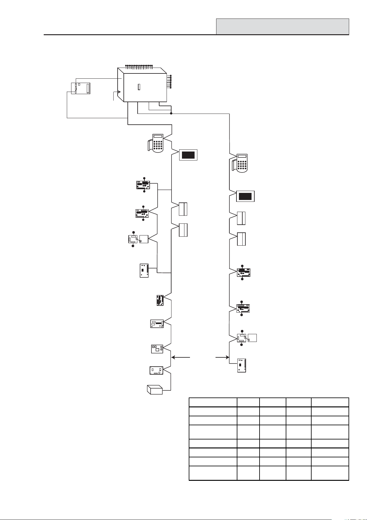
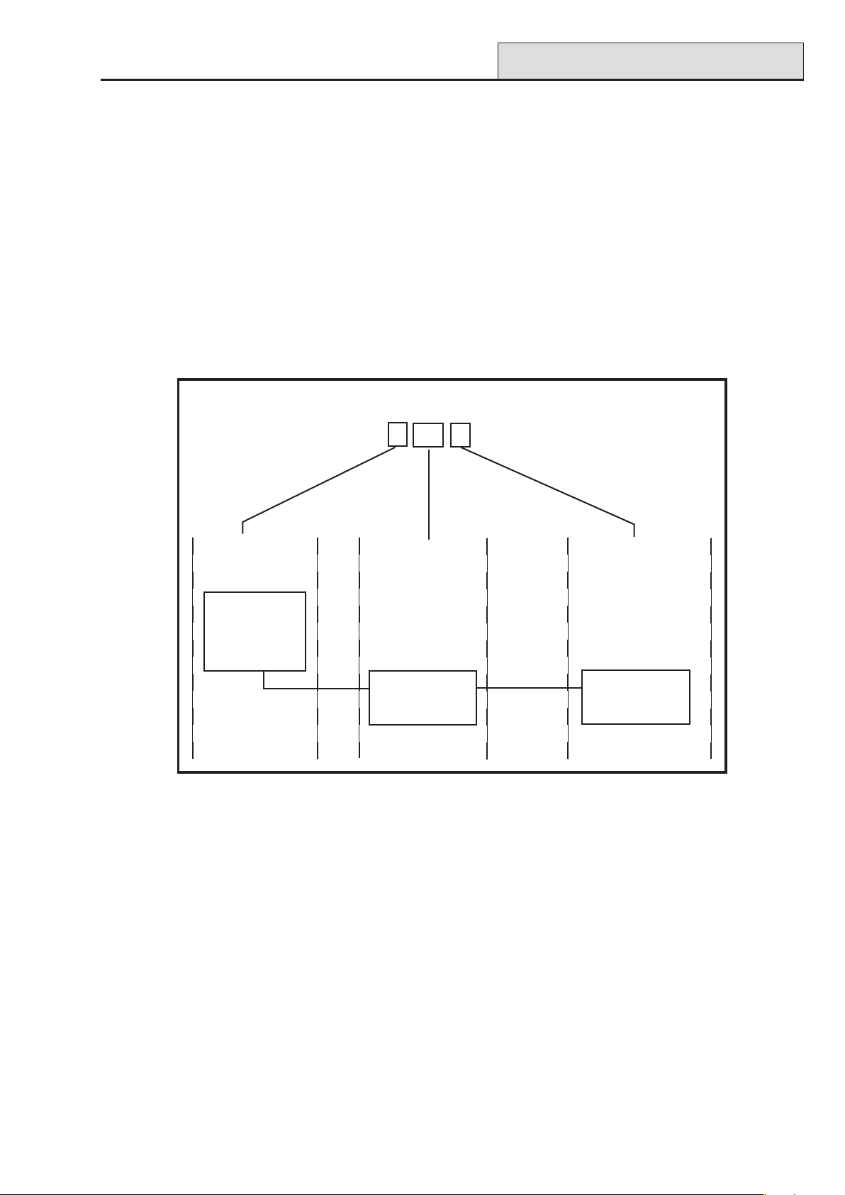
SECTION 2: SYSTEM ARCHTECTURE
16 zones on board
PSTN (comm 1)
Audio Interface
Module (1)
RS485 line
*
NOTE:
Valid addresses for the
keyprox are:
Line 1 (0, 1 & 2).
Line 2 (0, 1, 2, & 3 ).
This sets the address for both
the keypad and card reader
parts of the keyprox.
*
Certain keypad and
max addresses can
be replaced by a
combined keyprox unit.
NOTE:
RIOs, RF RIO's and
PSU's can be mixed on
the lines.
NOTE:
The Telecom, Printer Interface,
RS232, Ethernet and ISDN
modules can only be
connected to line 1.
If a Telecom module is attached,
keypad address E cannot be
connected to line 1(address E is
shown as 18 on the system).
If an RS232 module is attached,
keypad address D cannot be
connected to line 1 (address D is
shown as 17 on the system).
If an Ethernet module is attached,
keypad address B cannot be
connected to line 1 (address B is
shown as 15 on the system).
If an ISDN module is attached,
keypad address C cannot be
connected to line 1 (address C is
shown as 16 on the system).
RS232
Serial Port
(comm 6)
Power Unit P025
or
Power RIO P026
on board
telecom
area
Line
Smart PSU
P015
RF RIO Module
C076
Ethernet Module
E080 (comm 4)
Printer Interface
A134/A161
12
RIO
C072
OR
OR
4 outputs
8 zones
OR
RS232 Module
E054 (comm 2)
ISDN Module
E077 (comm 3)
Galaxy
Trigger
Header
Line
Line Line
4
3
Cable run 1 km (max)
*
K
eypads
CP027/
Keyprox
CP028
4 outputs
8 zones
4 outputs
8 zones
Telecom Module
E062 (comm 5)
8 outputs
on board
plus 6 outputs
on trigger header
Lines 2, 3 and 4 have
the same configuration
*
Max
MX03
OR
DCM
C080/81
Twisted Pair
Screened Cable
Touch
Center
CP040
OR
4 outputs
8 zones
4 outputs
8 zones
4 outputs
8 zones
*
Keypads
CP027/
Keyprox
CP028
Touch
Center
CP040
*
Max
MX03
DCM
C080/81
RIO
C072
OR
Smart PSU
P015
OR
Power Unit P025
or
Power RIO P026
OR
RF RIO Module
C076
GD-48 GD-96 GD-264 GD-520
Lines 12 2 4
Keypads 8 8 per line 8 per line 8 per line
Keyproxes 3 3 (line 1)
4 (line 2)
Touch Center 1 1 per line 1 per line 1 per line
MAX's 4 8 per line 8 per line 8 per line
DCM's 4 8 per line 8 per line 8 per line
RIO's/PSU's 4 4 (line 1)
6 (line 2)
Figure 2-1. Galaxy Dimension System Configuration
2-1
3 (line 1)
4 (line 2)
15 (line 1)
16 (line 2)
3 (line 1)
7 (lines 2, 3, 4)
15 (line 1)
16 (lines 2, 3, 4)
Page 14
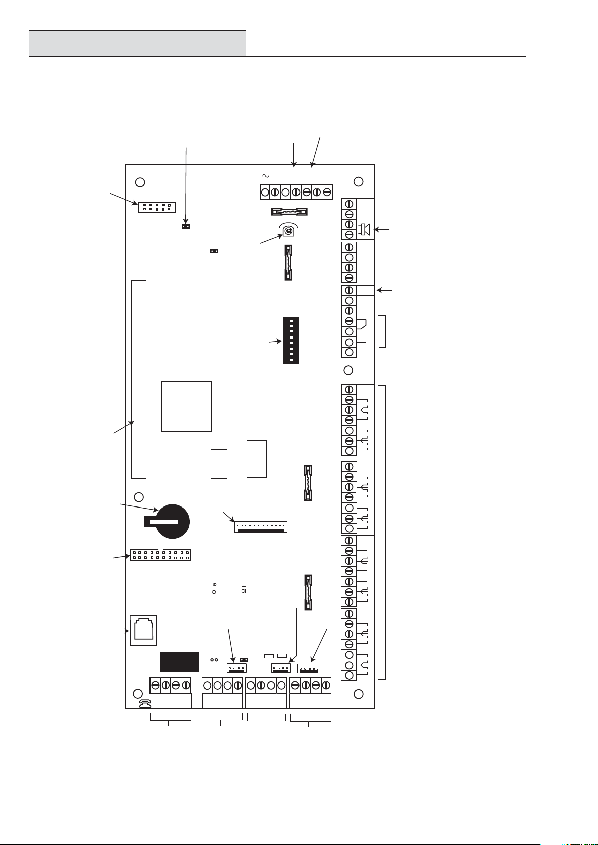
PCB Layout
PCB Layout
SPI
Program
Header
Jumper Lead
for off-wall
tamper switch
LK2
TAMPER
OFF WALL
BATTERY
START UP
LK4
BATT
Horn output
volume control
Pull-up switches
Leads for
lid tamper
AC
F1
AUX3
RIO
ON
microswitch
TAMP
LID
F2
SWITCH
7 8
6
4 5
2 3
1
SW3
Galaxy Dimension Installer Manual
Battery
terminals
14.5
-BAT
+BAT
G
N
D
AUX
TAMP
External
loudspeaker
AUX3
Relay
Output
N/C
C
N/O
4
2
RIO 1
13
+12V
4
3
RIO 0
2
1
Expansion card
interface
Memory
backup
battery
Debug
Header
Telecom
Socket
SKT2
MICRO
PROCESSOR
RAM1
Trigger
Header
termination
9
LK3 RS485 line 2, 680
FLASH
termination
9
Engineer socket
(RS485 Line1)
LK5 RS485 line 1, 680
LED1(for Telecoms)
AUX2
Engineer socket
(RS485 Line 2)
LED2 (for RS232)
AUX1
+12V
8
0V
7
6
0V
5
RIO 1
+12V
+12V
8
7
6
+12V
4
3
2
1
5
4
3
2
1
0V
0V
16 on-board zones
0V
0V
RIO 0
0V
0V
F3
F4
RS232 Port socket
OR
Zones 1-8 (RIO 1 line 1 (switch SW3-8 OFF))
Zones 1-8 (RIO 1 line 0 (switch SW3-8 ON))
NOTE: Zones 1-8 (RIO 0 line 1)
Fuse AUX2 controls
RS485 line 2, RIO 1 (zones 1-8)
Fuse AUX3 controls an independent
12V output which can be used for a
communicator or screw.
LINE
PHONE
ABAB
Telecom
Connect
A1
B1
B2
GND
+12V
RS485 line 1
A2
+12V
GND
RS485 line 2
TX
Figure 2-2. PCB Layout
2-2
NOTE: Fuse AUX1 controls
CTS
RX
RTS
RS485 line 1, RIO 0 (zones 1-8)
RS232 Port
Page 15
Galaxy Dimension Installer Manual
RS485 Expansion Module
The 7 transistorised outputs on the Galaxy Dimension can be configured to open collectors by setting the dip
switch SW3 to the OFF position.
NOTE: Output 2 on RIO 0 (relay output) is not affected.This is a form C relay that can switch up to 1 amp
at 24 volts DC.
The following table shows which outputs are controlled by which switches.
(SW3) RIO Output
10 1
20 3
30 4
41 1
512
613
714
Table 2-1. SW3 Transistorised Outputs Control
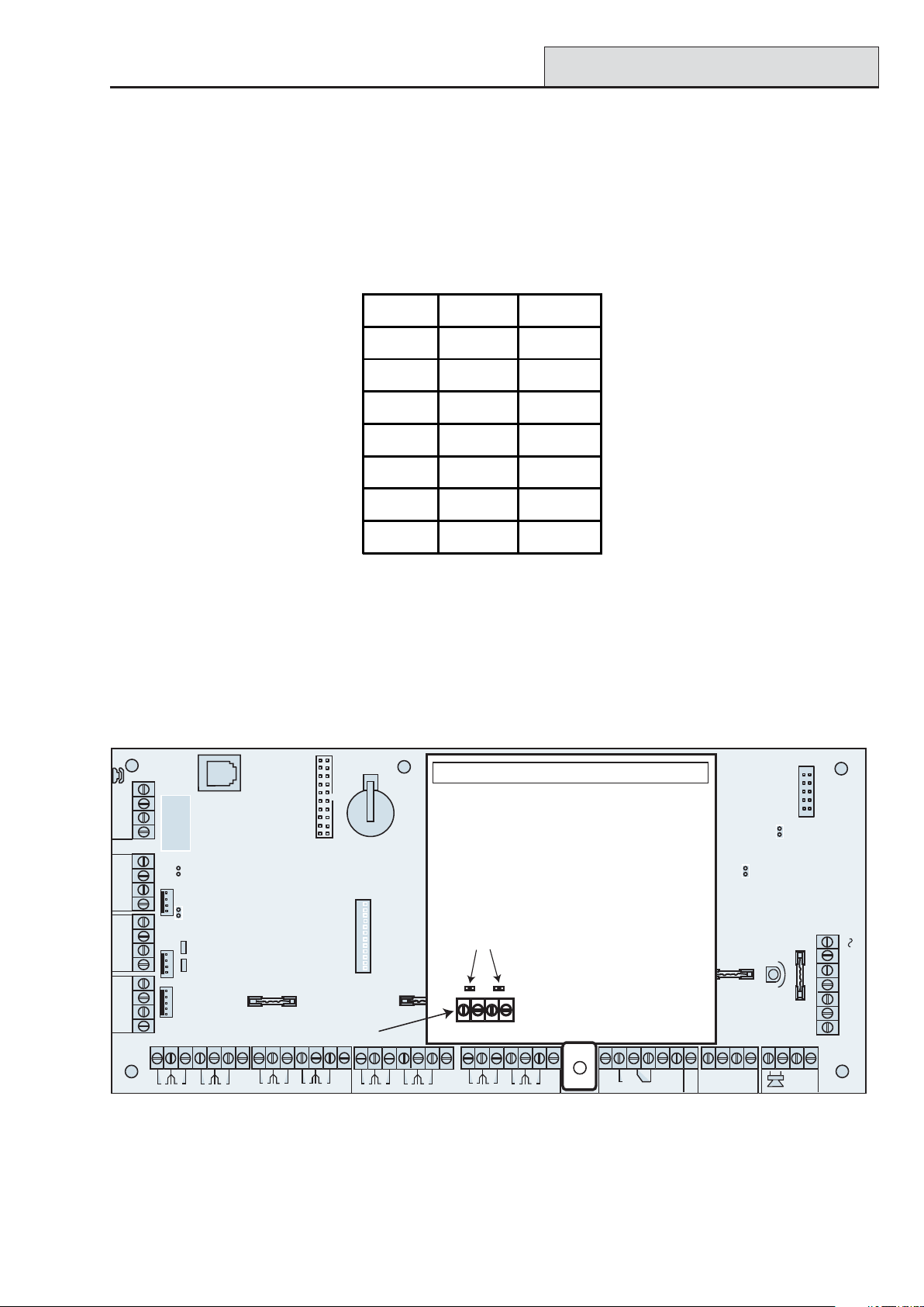
RS485 Expansion Module (GD-520 only)
The RS485 Expansion Module is attached to the GD-520 to give 2 extra RS485 (AB) lines.
This module can also be added to a GD-264 to convert it into a GD-520. Jumpers LK1 and LK2 can be
removed to disable the on-board end-of-line resistors.
SKT2
LINE
A
PHONE
B
AB
B1
A1
GND
+12V
B2
A2
GND
+12V
TX
RX
CTS
RTS
Twin
RS485
lines
LK1
A3
Jumpers
B3
A4
RS485
EXPANSION
MODULE
LK2
B4
ON
4 5
2 3
6
1
7 8
C
N/C
N/O
F1
-BAT
+BAT
14.5
AC
LID
TAMP
AUX
2
1
0V
+12V
4
3
0V
RIO 0
6
5
0V
+12V
8
7
0V
2
1
0V
+12V
4
3
RIO 1
0V
6
5
0V
+12V
8
7
0V
1
4
3
2
RIO 0
+12V
4
2
13
RIO 1
TAMP
G
N
D
Figure 2-3. RS485 Expansion Module
2-3
Page 16
Installation Recommendations
Galaxy Dimension Installer Manual
System Installation and Wiring
The installation and wiring must be performed by a competent engineer. For permanently connected equipment, a readily accessible disconnect device must be incorporated in the fixed wiring. The Galaxy Dimension
control panel must be connected to the a.c. mains supply (230/240 Va.c. 50 Hz) via a fused connection outlet
in accordance with EN60950-1: 2001
The fuse in the mains outlet must not exceed 3A.
WARNING: A means of isolation from the mains supply must be provided within 2 metres of
the control panel. Where live and neutral supplies can be identified, a fused spur
with a 3 amp fuse, must be fitted on the live circuit. Where live and neutral circuits
cannot be reliably identified, 3 amp fuses must be fitted to both circuits.
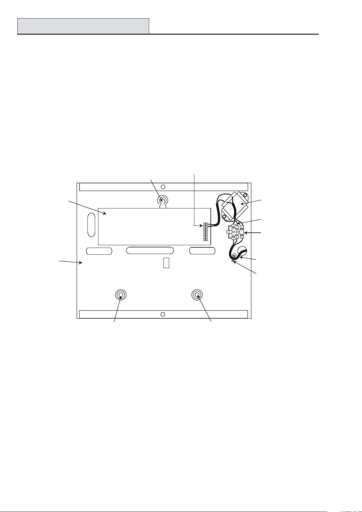
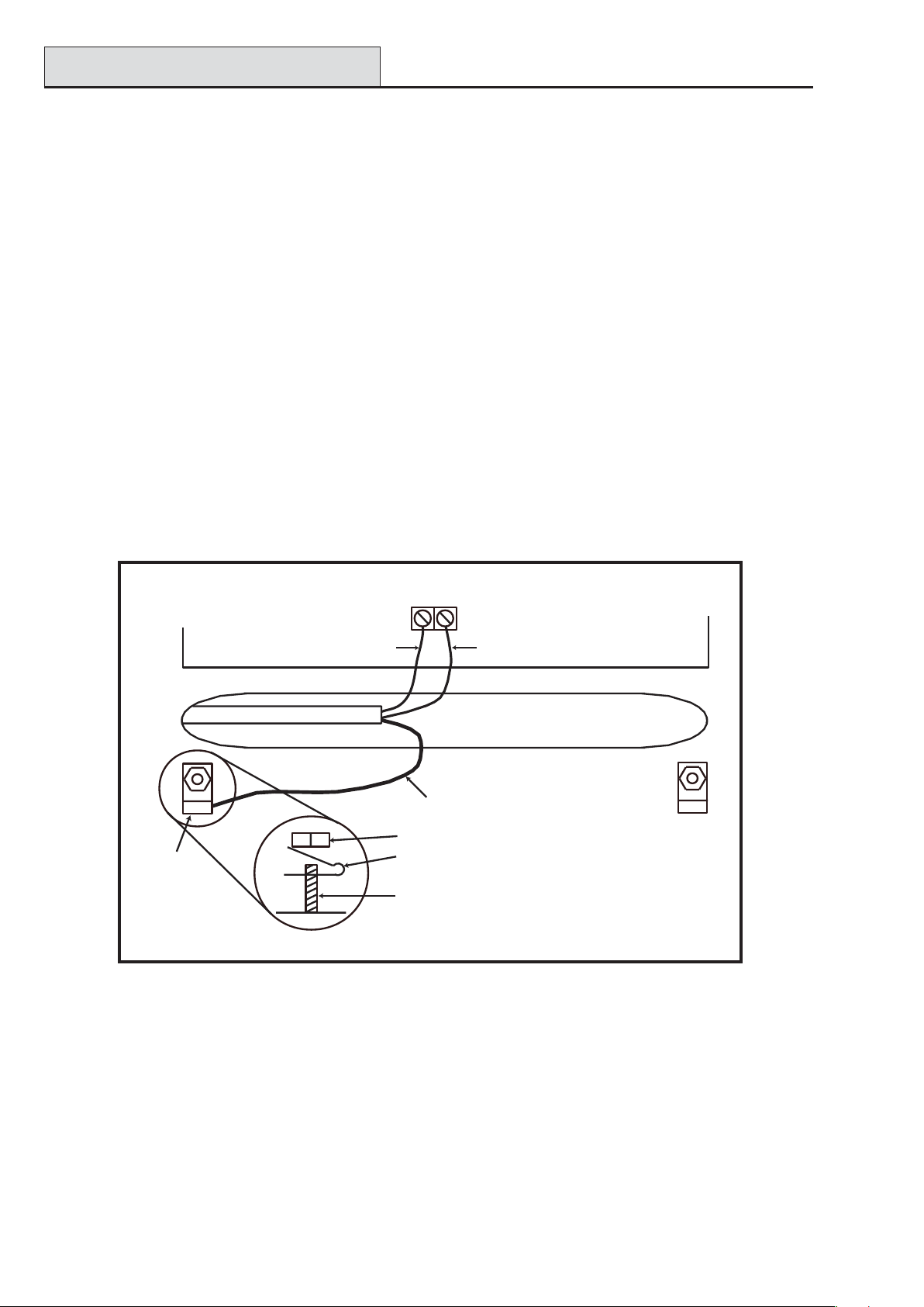
Route the mains cable through the hole on the right hand side of the enclosure base. Securely anchor the
cable to the box using the tie-wrap as shown in the following Figure:
Enclosure
base
AC connect
Attaching hole
PCB
Attaching hole
Keyhole
slot (top)
Figure 2-4. Securing the Mains Cable to the Enclosure Base
Mains
transformer
Earth wire
Terminal
block
Mains cable
Tie wrap
Secure the panel base to the wall using three 1.5" No. 8 round head steel screws through the holes provided.
The mains cable used must be a three core type (with green/yellow earth insulation) of adequate current
carrying capacity.
Connect the mains cable to the mains terminal block as follows:
• blue wire to the terminal marked N (Neutral)
• green/yellow wire to the terminal marked (Earth)
• brown wire to the terminal marked L (Live)
NOTE: No other connections to the mains connector are permitted.
All wiring must be in accordance with local regulations and the installation must conform to EN60950.
2-4
Page 17
Galaxy Dimension Installer Manual
System Wiring
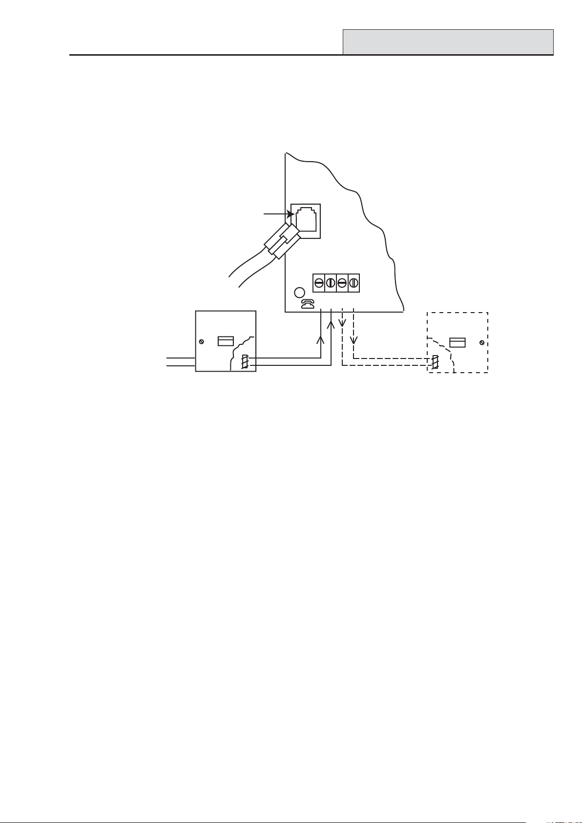
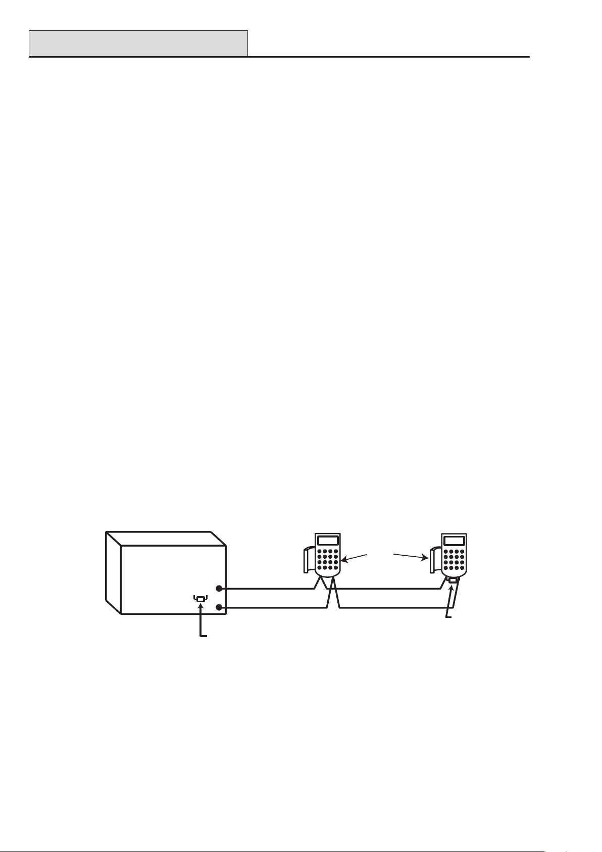
Connecting the Galaxy Dimension to the PSTN
The Telecommunications Network Voltage (TNV) port (terminals A and B on PCB) must be permanently
connected (hard-wired) to the PSTN via a master socket, refer to Figure 2-5.
Telecom
Socket
RJ11
Plug
PHONE
Master socket
LINE
ABAB
Secondary socket
Incoming
PSTN
Line
line 2
line 1
line 1
line 2
Figure 2-5. Connecting the Galaxy Dimension to the PSTN
NOTES: 1. Terminals 1 and 2 on the Master Socket must be hard-wired to LINE A and B
terminals on the Galaxy Dimension PCB. The connection is polarity independent.
2. It is strongly recommended that the Galaxy Dimension panel is the only device on the line.
3. If another device is to be connected to the line, connect the PHONE terminals on the PCB
to terminals 1 and 2 on a Secondary socket.
There are two methods of connecting the on-board Telecom Module to the PSTN:
Method 1
Using cable suitable for connection to 2.8 mm diameter screw terminals, strip back approximately 20 mm of
the outer sheath and then remove approximately 4 mm of the insulation from the wires to be connected to the
Galaxy Dimension PCB.
Connect terminals 1 and 2 on the Master socket across the LINE A and B terminals on the Galaxy Dimension
PCB, see Figure 2-5.
Method 2
Use a standard cable with RJ11 plug on one end and plug into the telecom socket on the Galaxy Dimension
PCB. Connect the other end of the cable to the Master socket as described in Method 1.
NOTE: Digital Subscriber Line (DSL) should not be used. If it is used, connect a suitable filter to the phone
line.
2-5
Page 18
System Wiring (cont’d)
Galaxy Dimension Installer Manual
Connecting Additional Telecom Apparatus
A secondary socket, allows additional telecom apparatus to be connected in series with the on-board telecom
module. Connect the PHONE terminals A and B on the PCB to the terminals on the secondary socket. See
Figure 2-5.
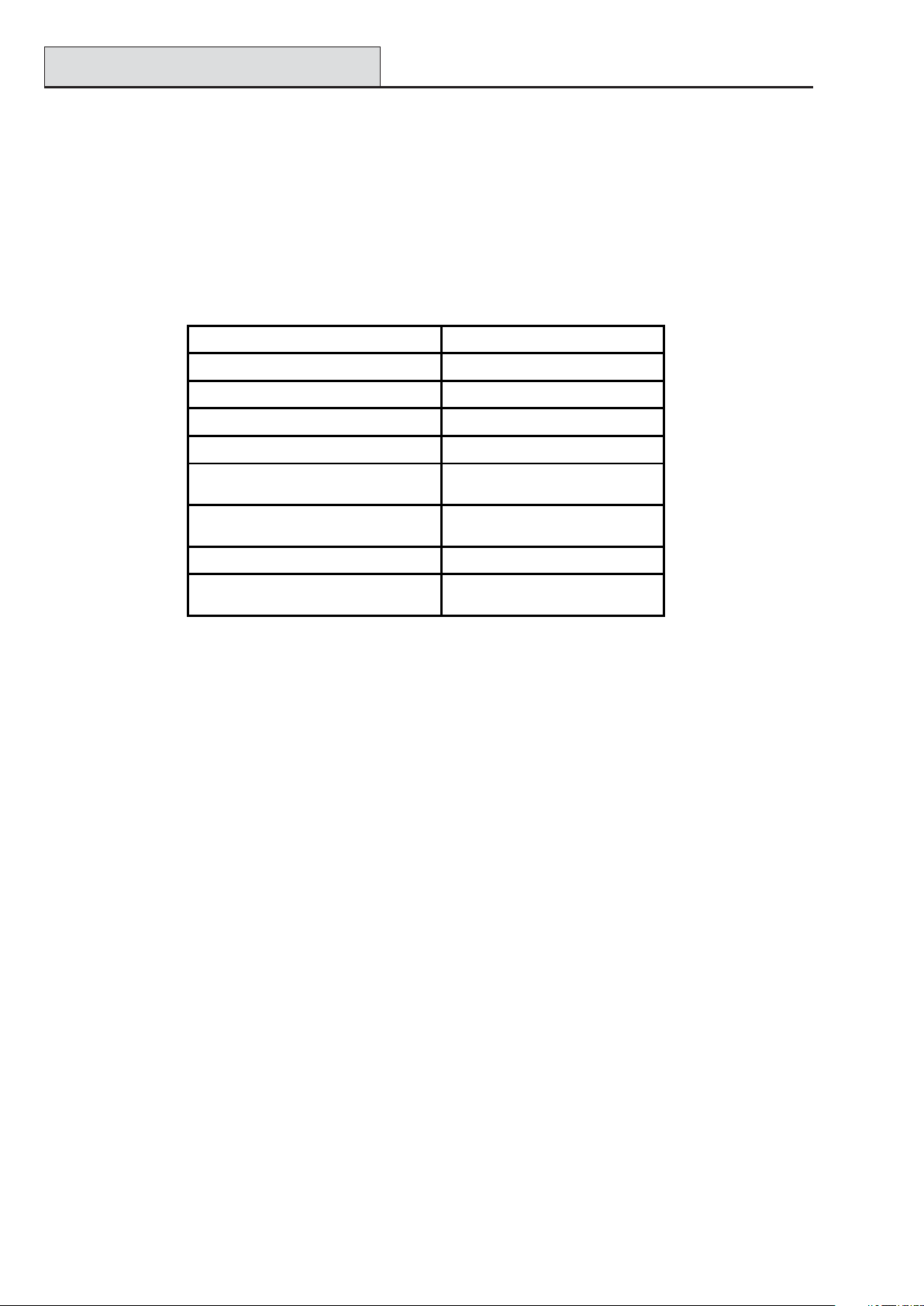
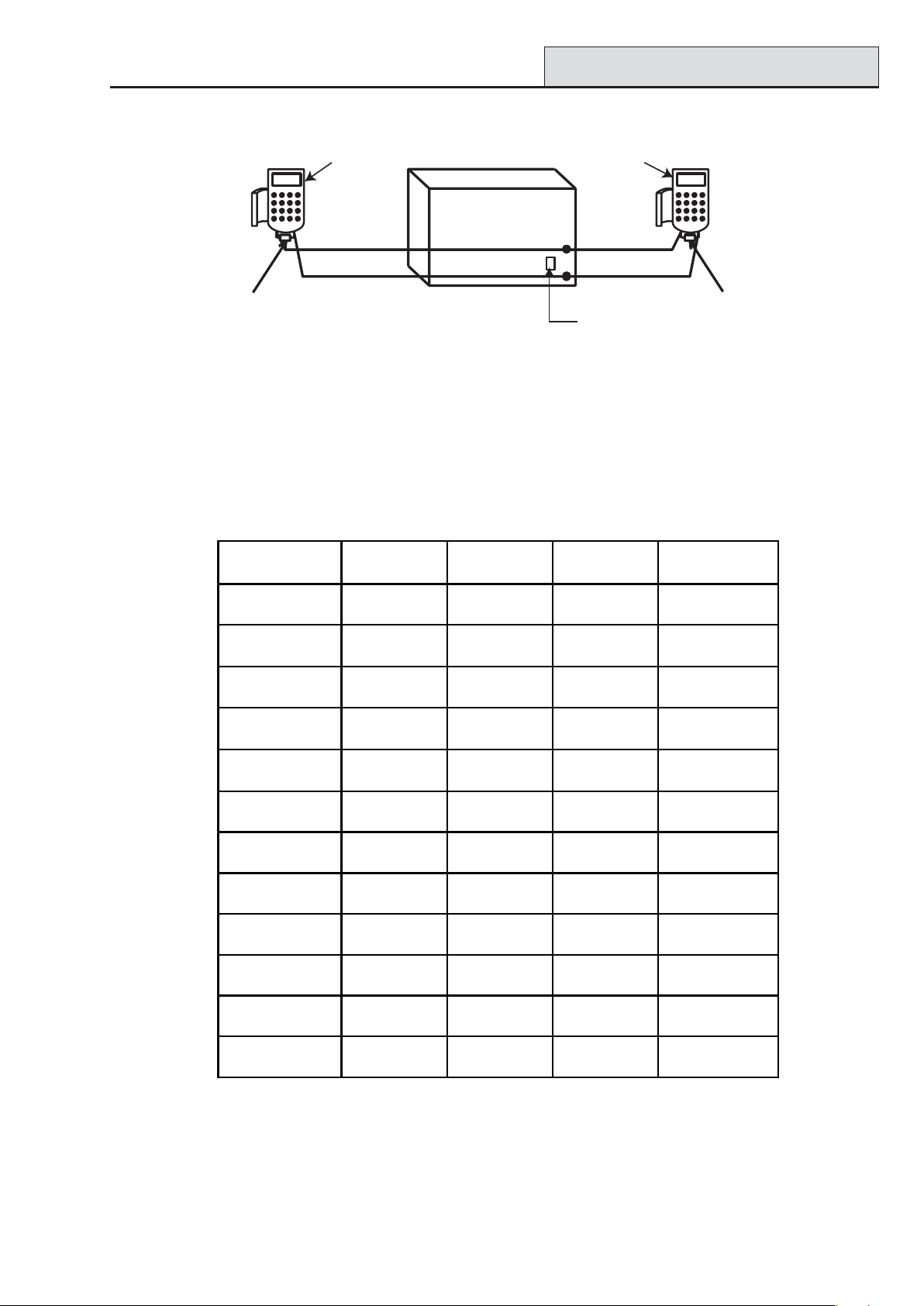
Line Monitoring
Under normal idle state conditions, the on-board Telecom Module monitors the PSTN line. The communication status is indicated by the state of the red LED (LED1) as shown in the following table:
LED STATE INDICATION
LED OFF No d.c. supply
ON - 01s, OFF - 0.9s Normal Communication
Single pulse at end of call Normal Communication
Flashing at end of alarm call Failed Communication
On during alarm monitoring,
Remote Servicing and SMS
Flickeri ng during alarm moni toring,
Remote servicing and SMS
Flashes in time with ringing signal Line Ringing
Pulses as each digit is dialled
Normal Communication
Poor Communication
Normal indication when
making call
Table 2-2. Comms Status
2-6
Page 19
Galaxy Dimension Installer Manual
Stand-by Battery
Stand-by Battery
The Galaxy Dimension control panels can accommodate up to 2 x 17 Ah batteries. Ensure that the battery
connector leads on the control panel Powers Supply Unit (PSU) are connected to the correct terminals on the
battery.
CAUTION: There is a risk of explosion if the battery is replaced by an incorrect type.
Dispose of used batteries according to the instructions.
lenaPlortnoCyrettaB
TAB-lanimretev-
TAB+lanimretev+
Table 2-3. Battery/Control Panel connections
Battery Start-up
The system can be powered up via the Battery Start-up jumper if there is no AC power. To do this, short
out the Battery Start-up jumper for the duration of the configuration process only. Never leave the Battery
Start-up connected or else deep discharge of the Stand-by Battery will occur.
On-Board Power Supply Unit
The on-board Power Supply Unit (PSU) supplies and monitors power to the system and peripherals. The
following table shows the fuse name and value in amps.
The Galaxy Dimension control panel contains four fuses. Details are given in the following table.
FUSE NAME VALUE (AMPS) PROTECTS TYPE
AUX1 1.0 RS485 Line 1, RIO 0, Zones 1-8: +12V,
on-board comms
AUX2 1.0 RS485 Line 2, RIO 1, zones 1-8 +12V 20 mm, anti-surge
AUX3 1.0 +12V AUX3 terminal 20 mm, anti-surge
BATT 1.6 Battery 20 mm, anti-surge
Table 2-4. On-board PSU Fuses
Power Monitoring Characteristics: Low battery level: 11.2V
Deep discharge protection: 10.5V
Overvoltage protection: 14.7V
The PSU total capacity is 2.5A. Internally the PSU is split in two in order to ensure sufficient current is always
available for stand-by battery recharge. The PSU capacity is broken down as follows:
20 mm, anti-surge
• Battery: 1.25A
• Control PCB: 0.25A
• AUX +12V: 1.00A
The PSU is available for zones/outputs and peripherals.
2-7
Page 20
Memory
Galaxy Dimension Installer Manual
Memory
The Galaxy Dimension control panel is fitted with a memory chip with its own battery backup on the main
PCB. This allows the panel to retain the system configuration, programming details and the event log for up to
a year when both the mains power and standby battery have been disconnected. The memory backup battery
must be kept in place to retain the memory during a mains failure. Re-apply power, this is known as a warm
start.
To completely erase the system memory and return to the default settings, place a piece of thin card between
the retaining clip and the memory backup battery then remove all power to the PCB for one minute. Re-apply
power and remove the card. This is known as a cold start.
The memory backup battery shoud be replaced every 5 years.
CAUTION: There is a risk of explosion if the battery is replaced by an incorrect type.
Dispose of used batteries according to the instructions.
CAUTION: Do not overstress the retaining clip when removing and installing the backup
battery. The clip must maintain a firm pressure on the backup battery at all times.
RS485 Data Communication Bus (AB Lines)
Communication between the Galaxy control panels and the modules attached to the system takes place on the
AB lines. The communication protocol is RS 485 format. The control panel constantly monitors the modules
attached to it. A break in the communication from any of the modules generates a module tamper alarm
RS485 Wiring Configurations
The system must be wired in a daisy-chain configuration. That is the A line from the previous module is
connected to the A terminal of the current module and then on to the A line of the next module.
The RS485 (AB) line must have a 680 Ω resistor fitted across the A and B terminals of the last module on the
line. If two lines are connected, both ends must be terminated with 680 Ω resistors and the appropriate link
(LK3 or LK5) removed.
Keypad/Keyprox
OR
Galaxy
Control
Panel
680 Ω
A
A
B
Fit LK3/LK5 on PCB
Module
B
AB
680 Ω EOL
Figure 2-6. Daisy Chain Configuration
Each AB line can run in two directions from the control panel.
• Remove link LK3 (RS485 line1) or link LK5 (RS485 line2).
• Run two lines from the A and B terminals of the line.
• Terminate both Ends of Line (EOL) with a 680 ohm resistor.
NOTE: It is permissable to have different configurations on each line. For example, line 1 - Daisy chain;
line 2 - twin AB daisy chain.
2-8
Page 21
Galaxy Dimension Installer Manual
RS485 Recommendations
Keypad/Keyprox
OR
Module
Keypad/Keyprox
OR
Module
Galaxy
Control
A
680 Ω EOL
B
Panel
A
B
Remove
LK3/LK5
B
A
680 Ω EOL
Figure 2-7. Twin AB Line Daisy-Chain configuration
RS485 Wiring Recommendations
To ensure that the system communicates at the maximum level of efficiency, the following recommendations
must be adhered to:
1. The maximum number of devices on each line are:
GD-48
(Line 1 only)
GD-96
(Lines 1-2)
GD-264
(Lines 1-2)
GD-520
(Lines 1-4)
Keypads
Keyprox
Touch Center
RIO's/SPSU's
RF RIO
MAX/DCM
RS232
Telecoms
Printer
ISDN
Ethernet
8 8 per line 8 per line 8 per line
3
1 1 per line 1 per line 1 per line
4
4
4 8 per line 8 per line 8 per line
1 1 (line 1 only) 1 (line 1 only) 1 (line 1 only)
1 1 (line 1 only) 1 (line 1 only) 1 (line 1 only)
1 1 (line 1 only) 1 (line 1 only) 1 (line 1 only)
1 1 (line 1 only) 1 (line 1 only) 1 (line 1 only)
1 1 (line 1 only) 1 (line 1 only) 1 (line 1 only)
3 (line 1)
4 (line 2)
4 (line 1)
6 (line 2)
4 (line 1)
6 (line 2)
3 (line 1)
4 (line 2)
15 (line 1)
16 (line 2)
15 (line 1)
16 (line 2)
3 (line 1)
7(lines 2, 3, 4)
15 (line1)
16 (lines 2, 3, 4)
15 (line 1)
16 (lines 2, 3, 4)
Audio Interface
1 1 (line 1 only) 1 (line 1 only) 1 (line 1 only)
Table 2-5. Communication Devices
2. The system must be wired in a daisy-chain configuration. Spur and star configurations must not
be used as they reduce the immunity to electrical interference.
3. The cable used must screened twisted pair (Part No W002) to connect the RS485 (AB) line. This
would be CAT5 or Belden 8723 equivalent.
2-9
Page 22
RS485 Recommendations
Galaxy Dimension Installer Manual
4. Shielded twisted pair cable, where used, is connected to the earthing pillar on the Galaxy control
panel using the P-clip and nut supplied (refer to Figure 2-8).
5. The RS485 (AB) line must have a 680 Ω resistor fitted across the A and B terminals of the last
module on the line. If twin lines are connected, both ends must be terminated with 680 Ω resistors and
the appropriate link on the control panel PCB must be removed (refer to figure 2-7).
6. There must only be a single AB pair of wires in each of the cables.
7. The minimum supply voltage level is 10.5 Vd.c. with 12.5 Vd.c. being the recommended working
minimum.
8. The power supply in the Galaxy control panel and remote power supplies must not be connected
in parallel.
9. The 0 V of all remote power supplies should be connected in common to the 0 V of the Galaxy
control panel.
10. Ensure that any extension loudspeakers are not wired in the same cable as an AB pair of wires.
11. Where possible, ensure that the AB cable is at least 30 centimetres away from any other cables.
12. Where possible, ensure that the AB cable does not run parallel to other cables for extended
distances (maximum 5 metres).
P-clip
AB connectors
A
data line
RS 485 cable
Nut
P-clip
Earthing pillar
(threaded)
B
data line
Cable screen
Figure 2-8. Connection of cable screen using P-Clip
2-10
Page 23
Galaxy Dimension Installer Manual
Zone Addresses
Zones
The default setting for the zones on the Galaxy Dimension are as follows:
Zone 1001 = Final
Zone 1002 = Exit
All remaining zones = Intruder
Zone Addresses
Each zone has a four digit address; 1004, 4136. The address is made up of three reference numbers as shown
in the following figure:
Example: 3057
3
05 7
Represents Panel
Line No.
GALAXY
PANEL
1 2 3 4
Represents
RIO Address
RIO
ADDRESS 05
Figure 2-9. Zone Addresses
For example, zone 3057 is the detector connected to line 3, RIO 05, zone 7.
Represents
Zone No. 1-8 on
RIO
ZONE 7
2-11
Page 24
RIO Switch
Galaxy Dimension Installer Manual
Zone Addressing with Onboard RIO Switch (Line 0 Switch)
The RIO switch (SW3, dipswitch 8) controls the ordering of the on-board RIO’s. This dipswitch must be set
before powering up the panel. Setting the switch to ON sets the on-board RIO1 to operate on line 0 and
allows a RIO addressed as 1 to be connected to line 1, giving a total of 15 RIO’s on a GD-264 and
GD-520. The RIO switch only needs to be activated when the full compliment of RIO’s is required, or when
replacing a Galaxy 512 panel with a power supply/RIO already using address 1.
NOTE: The RIO switch is not functional on other variants. It defaults to the Switch off configuration.
Switch off (default)
When the switch is set to this mode, the onboard RIO’s configure to the following addresses:
Onboard RIO0 Zone address range: 1001-1008 Outputs: 1001-1004
Onboard RIO1 Zone address range: 1011-1018 Outputs: 1011-1014
Switch on
When the switch is set to this mode, the onboard RIO’s configure to the following addresses:
Onboard RIO0 Zone address range: 1001-1008 Outputs: 1011-1014
Onboard RIO1 Zone address range: 0011-0018 Outputs: 0011-0014
Panel On-Board RIO Address Range Total
on-board
Zon e s
GD-48 1001 - 1008, 1011 - 1018 16 4 2 - 5 48
1001 - 1008, 1011 - 1018 (switch off) 16 4 2 - 5
GD-96
1001 - 1008, 0011 - 0018 (switch on) 16 5 1 - 5
GD-264 1001 - 1008, 1011 - 1018 (switch off) 16 14 2 - 9, A - F
1001 - 1008, 0011 - 0018 (switch on) 16 15 1 - 9, A - F
1001 - 1008, 1011 - 1018 (switch off) 16 14 2 - 9, A - F
GD-520
1001 - 1008, 0011 - 0018 (switch on) 16 15 1 - 9, A - F
Max No of
External RIO's
(Line 1)
Valid E xternal
RIO Addresses
(Line 1)
Total Zone
Addresses
(Switch ON)
96
264
520
Table 2-6. Zone Address Ranges
2-12
Page 25
Galaxy Dimension Installer Manual
Wiring Zones
Wiring Zones
The zones on Galaxy Dimension panels can be Double Balanced (default) or End of Line. Zones can be
programmed with different resistance ranges for zone status activation (see Parameter 51.46 =
Parameters.Zone Resistance). Refer to Table 2-7 (Double Balanced) or Table 2-8 (End of Line) for
details of the zone resistance and resulting conditions.The system default is Option 9, giving fault monitoring on
1k double balanced wiring.
NOTE: The circuit debounce time (the period the zone must remain in a state to register a change in condi-
tion) is 300 milliseconds by default.
Option 01 - 1k Option 03 - 2k2 Option 05 - 4k7 Option 07 - 5K6 Option 09 - 1k Fault
Tamper S/C 0 - 800 0 - 1800 0 - 3700 0 -1400 0 - 800
Low Res 800 - 900 1800 - 2000 3700 - 4200 1400 - 2800 800 - 900
Normal 900 - 1200 2000 - 2500 4200 - 5500 2800 - 8400 900 -1200
High Res 1200 - 1300 2500 - 2700 5500 - 6500 8400 - 9800 1200 - 1300
Open 1300 - 12000 2700 - 12000 6500 - 19000 9800 - 12600 1300 - 3500
Fault - - - - 3500 - 4500
Masked 12000 - 19000 12000 - 15000 19000 - 22000 12600 - 22000 4500 - 19000
Tamper O/C 19000 - infinity 15000 - infinity 22000 - infinity 22000 - infinity 19000 - infinity
Table 2-7. Double Balanced Zone Resistance and Conditions
Option 09 - 1k Fault Double-balanced (default)
The wiring in Figure 2-10 should be used if the detector uses combined fault and mask signalling. A mask
condition is generated if an alarm and fault are signalled at the same time. Alternatively, if the detector has
seperate fault and mask indications then the wiring in Figure 2-11 should be used.
1k
Zone
Alarm N/C Fault N/C
Tamper N/C
100 m
Figure 2-10. Option 09 - Double balanced 1k Fault Monitoring Wiring
3k
1k
Zone
Figure 2-11. Option 09 - Double balanced 1k Fault/Mask Monitoring Wiring
NOTE: N/C = Normally Closed.
1k
Alarm N/C
Tamper N/C
2-13
100 m
3k
Fault N/C
12k
Anti-Mask N/C
1k
Page 26
Wiring Zones (cont’d)
Galaxy Dimension Installer Manual
When this wiring mode is employed, only one detector which can report fault conditions should be connected
to the zone. A maximum of two detectors or contacts of any type should be connected to a zone when this
mode is selected. It is recommended that zone cable lengths are kept below 100m in this configuration.
NOTE: The recommended maximum cable run from a zone to a detector is 500 metres in all other configu-
rations.
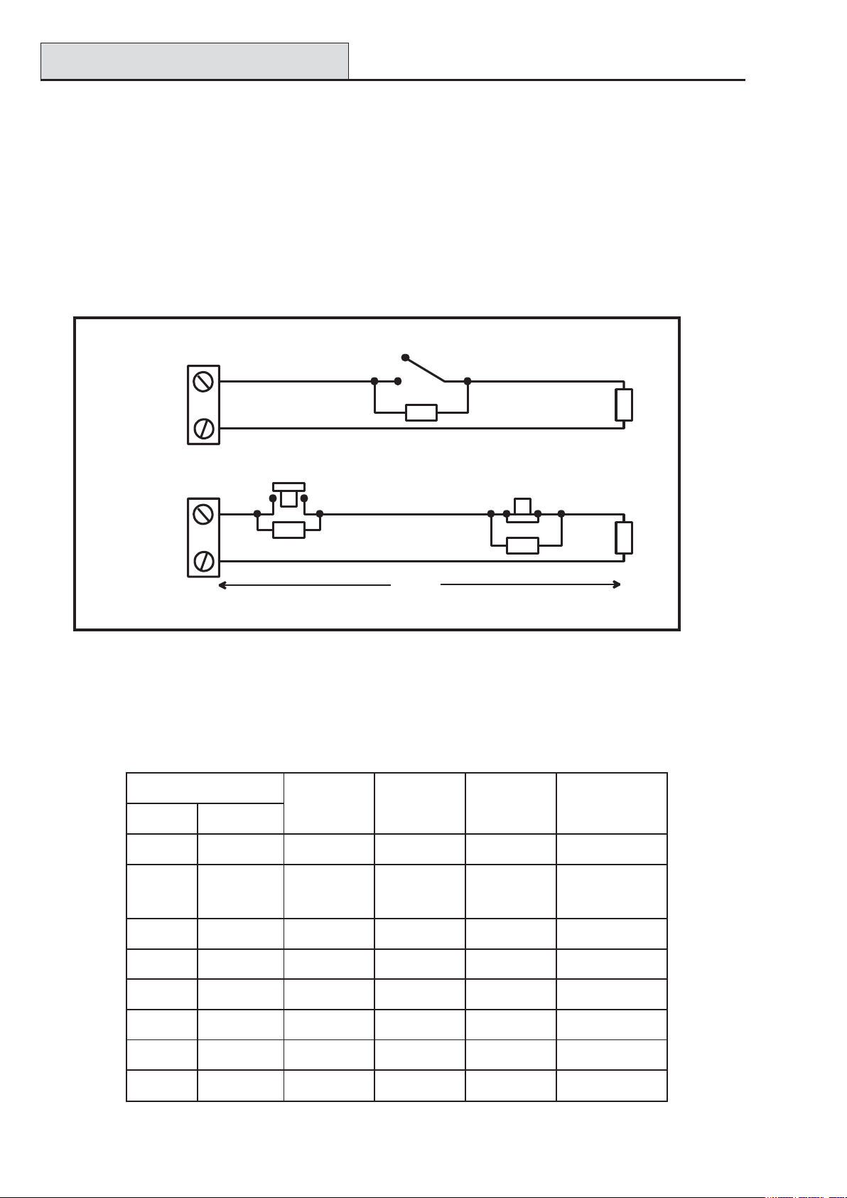
Option 02 - 1k Option 04 - 2k2 Option 06 - 4k7 Option 08 - 5k6 Option 10 -1k Fault
Tamper S/C 0 - 800 0 - 1800 0 - 3700 0 - 1400 0 - 800
Low Res 800 - 900 1800 - 2000 3700 - 4200 1400 - 2800 800 - 900
Normal 900 - 1200 2000 - 2500 4200 - 5500 2800 - 8400 900 - 1200
High Res 1200 - 1300 2500 - 2700 5500 - 6500 8400 - 9800 1200 - 1300
Fault - - - - 1300 - 4500
Masked 1300 - 12000 2700 - 12000 6500 - 19000 9800 - 19000 4500 - 19000
Open 12000 - infinity 12000 - infinity 19000 - infinity 19000 - infinity 19000 - infinity
Table 2-8. End of Line Zone Resistance and Conditions
Option 10 - 1k Fault End-Of-Line
The wiring in Figure 2-12 should be used if the mode is end-of-line. Fault and mask indications can only be
signalled if the detector has seperate fault and mask indications.
3k
Zone
Alarm N/C
Tamper N/C
Fault N/C
100 m
Figure 2-12. Option 10 - End of Line Zone/Detector wiring
When this wiring mode is employed, only one detector which can report fault conditions should be connected
to the zone. A maximum of two detectors or contacts of any type should be connected to a zone when this
mode is selected. It is recommended that zone cable lengths are kept below 100m in this configuration.
12k
Anti-Mask N/C
1k
NOTE: The recommended maximum cable run from a zone to a detector is 500 metres in all other configu-
rations.
2-14
Page 27

Galaxy Dimension Installer Manual
Wiring Zones (cont’d)
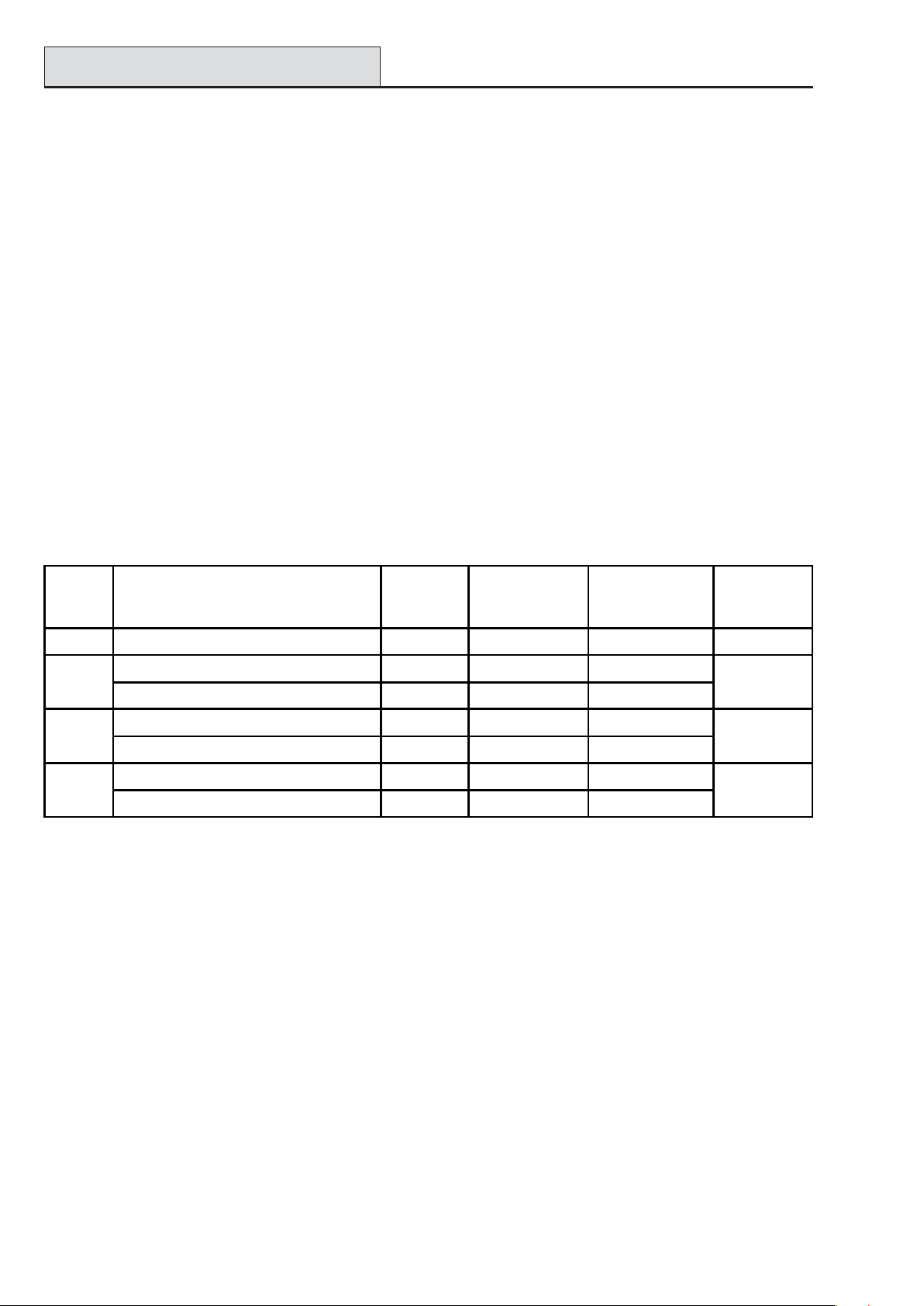
Wiring Multiple Detectors
Multiple detectors can be wired into a single zone when using preset 1 as shown in the following Figure. The
maximum number of detectors that can be connected to a single zone is ten.
(10 max)
N/C TAMP
1k
1%
1k
Zone
N/C
Alarm
1k
1%
N/C
Alarm Alarm Alarm
N/C
1k
1%
500 m
N/C N/C
1k
1% 1%
Figure 2-13. Zone to Multiple Detector Wiring
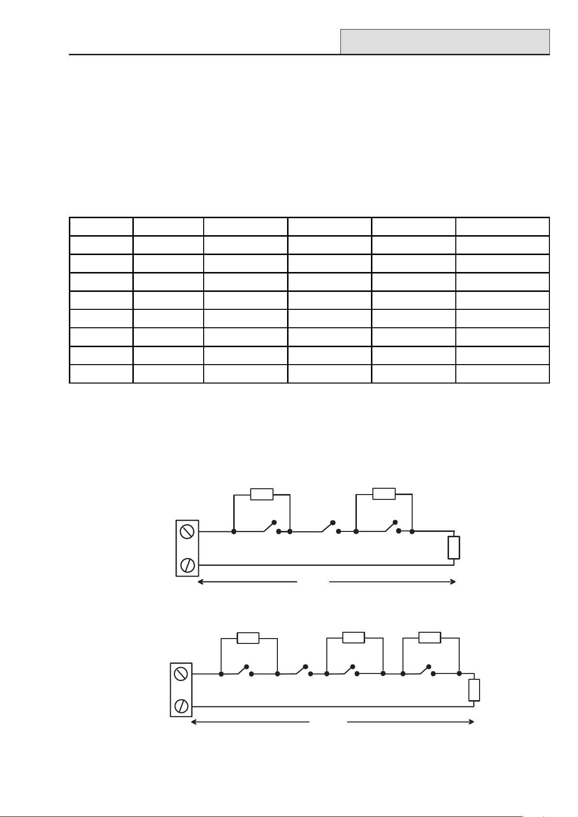
Wiring Keyswitches
Latching or spring loaded keyswitches can be used to set and unset the Galaxy Dimension panels; option
52 = PROGRAM ZONES has provision to accommodate both types of transition.
If the keyswitch latches, the transition from 1 kΩ to 2 kΩ initiates the setting procedure of an unset system,
the transition from 2 kΩ to 1 kΩ instantly unsets a set system. If the system is already set, then the transition
from 1 kΩ to 2 kΩ has no effect. If the system is unset, the transition from 2 kΩ to 1 kΩ has no effect. This
is programmed as a Keyswitch in the PROGRAM ZONES option.
If the keyswitch is spring-loaded (returns to its normal position), the transition from 1 kΩ to 2 kΩ initiates the
setting procedure of an unset system and instantly unsets a set system, the transition from 2 kΩ to 1 kΩ - the
return to the normal position - has no effect. This is programmed as a Keyswitch in the PROGRAM
ZONES option.
2-15
Page 28
Terminator Zone Wiring
Galaxy Dimension Installer Manual
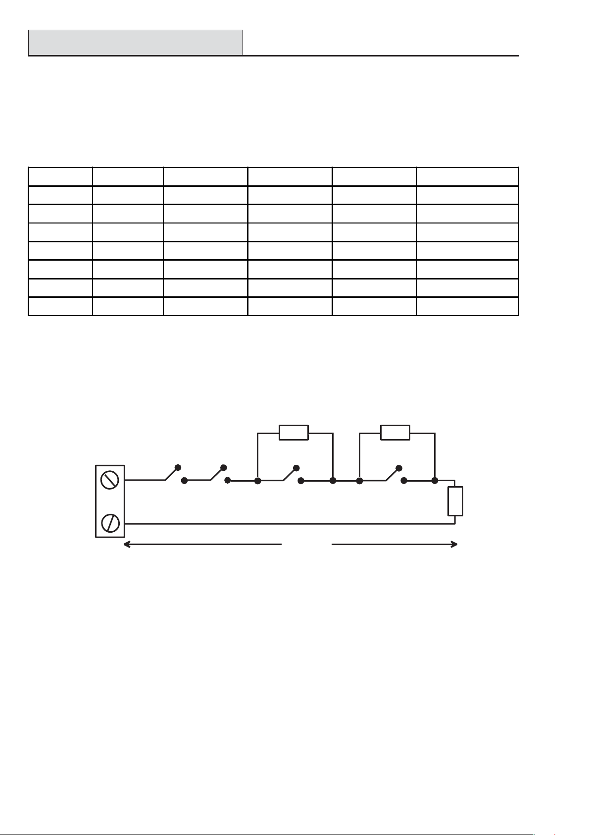
Wiring Terminator Buttons
Zones programmed as Push-Set (terminator) buttons can be open going closed (2 kΩ to 1 kΩ) or closed
going open (1 kΩ to 2 kΩ). The first activation of the terminator button initialises its status to the system.
NOTE: The first activation of a terminator may not set the system as this can be the initialisation routine. If
the system continues setting, push the button again. The system will set on the second push. This
initialisation only occurs on the first setting. All subsequent setting routines set on the first push of the
terminator.
The wiring of the terminator and keyswitch zone type is shown in the following figure:
Keyswitch
zone
Push-set
zone
Open - Closed
1k
1%
1k to unset, 2k to set
1k
1%
OR
500m
Closed - Open
1%
1k
Figure 2-14. Terminator and Keyswitch Zone Wiring
Outputs
The Galaxy Dimension control panel on-board outputs are detailed in the following table:
sserddAtuptuO
tluafeDelbanE0eniL
tluafeD
noitcnuF
epyTgnitaR
1k
1k
1%
1%
etatSlamroN
)pu-llup3k3htiw(
10011001slleBdesirotsis
20012001ebortSeloPelgniS
30013001APdesirotsisnarTAm0
40014001teseRdesirotsisnarTAm004,V21evitisoP
11011100teSdesirotsisnarTAm004,V21evitisoP
21012100redurt
31013100mrifnoCdesirotsisnarTAm004,V21evitisoP
41014100teseRdesirotsisnarTAm004,V
nIdesirotsisnarTAm004,V21evitisoP
narTAm004,V21evitisoP
A1,V03desigrene-eD
revOegnahC
)OCPS(yaleR
04,V21evitisoP
21evitisoP
Table 2-9. Outputs
2-16
Page 29
Galaxy Dimension Installer Manual
Output Applications
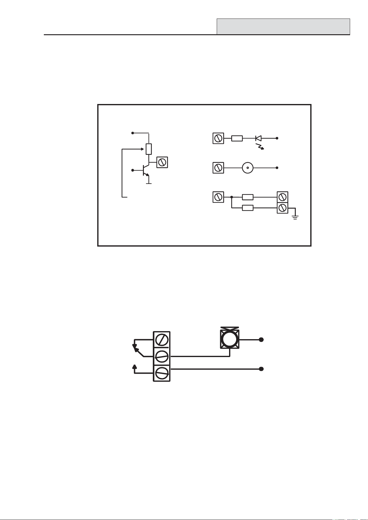
Output Applications
The outputs on the Galaxy panels, with the exception of the SPCO relay output, are transistorised outputs;
negative applied (positive removed) by default. These supply up to 400 mA and can be used to drive the
necessary output devices.
NOTE: The polarity of each output can be changed using option 53 = PROGRAM OUTPUTS
Transistorised Output
+12 V
3k3Ω
0 V
Switch out 3k3Ω
to give open collector
Output
Output must be
open collector
*
Typical Applications
A) LED
Output
1kΩ (typical)
B) Bell
Output
C) Output used to trigger zone
Output
NOTE: If the output used is one of the panel's
on-board outputs, then substitute this resistor
with a 680 Ω resistor.
LED
Bell
1%
*
1kΩ
1%
1kΩ
+12 V
+ 12 V
zone
Figure 2-15. Output Configuration and Typical Applications
Note: For the appropriate 3k3Ω pull-up resistor refer to DIP switch SW3 (Table 2-1).
The relay output is a single pole change over; this can be used to drive output devices that require a clean set
of contacts, isolated from the output voltage.
Horn
Normally
closed
+12 V
Single Pole
Change - 0ver
relay contacts
0 V
Normally open
Figure 2-16. Single Pole Change–Over Relay Output Configuration and Typical application
2-17
Page 30
Trigger Header
Galaxy Dimension Installer Manual
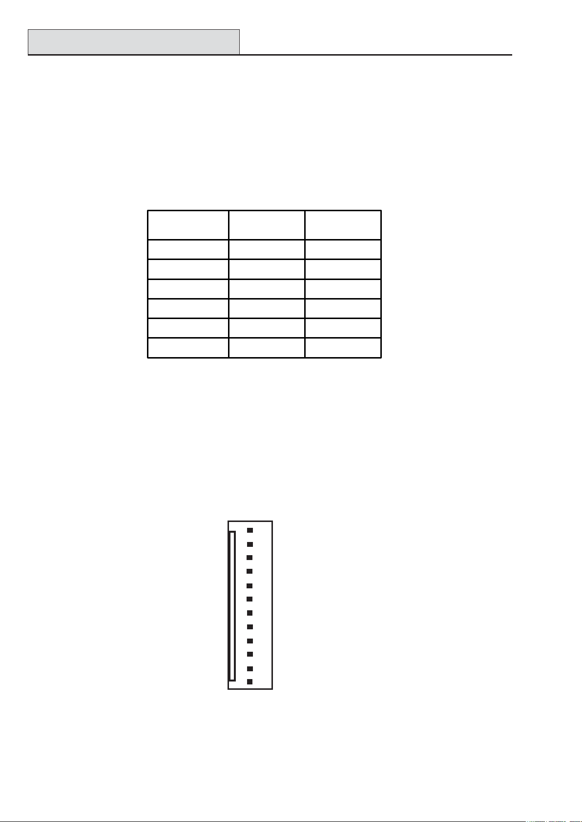
Trigger Header
The Trigger Header on the Galaxy Dimension is a set of pins that consist of programmable outputs for an
external communication module. The connection is via an optional ribbon cable.
Trig 1-6
There are six trigger outputs, that can be used as communication triggers, but can also be used for any other
purpose. By default these outputs are programmed as positive. They are designed to sink current (to 0V) not
source current (from 12V). The function of these outputs are as follows:
Output
Address
0001 Fire 100
0002 Panic 100
0003 Intruder 100
0004 Set 100
0005 Omit 100
0006 Confirm 100
Default
function
Current (mA)
Table 2-10. Trigger Output functions
The function of the trigger outputs can be programmed in menu option 53 = Program Outputs.
Supply
A 100 mA, 12V output is also provided. This output is fused by the on-board AUX3 FUSE (F2).
+12V
Not Used
Not Used
Trig 6
Trig 5
Trig 4
Trig 3
Trig 2
Trig 1
Not Used
Not Used
GND
Figure 2-17. Trigger Header
2-18
Page 31

Galaxy Dimension Installer Manual
SPI Key
Control
Panel
(part view)
SPI
Program
Header
Fitted
here
SPI Key
SPI Header
The SPI (Serial Peripheral Interface) key is an engineering peripheral used for copy/overwriting programming
data and carrying out software upgrades.
Fitting the SPI Key
The SPI key is fitted directly on to the Galaxy Dimension control panel.
CAUTION: Always power down the panel BEFORE removing or connecting the SPI key.
Failure to do so may result in damage to the SPI key. Never “hot-plug” the SPI
key.
The SPI Key has a 10-way connector. These locate on to the 10 pins of the SPI Program Header
(see Figures below).
NOTE: The SPI Key should only be fitted in the direction shown in Figure 2-19.
10-way
connector
Hinged
cap
Figure 2-18. SPI Key
Figure 2-19. Location of SPI Key on Program Header
1. Release the hinged cap to expose the 10-way connector.
2. Plug the SPI Key on to the Program Header on the Galaxy Dimension control panel.
Removing the SPI Key
CAUTION: Always power down the panel BEFORE removing or connecting the SPI key.
Failure to do so may result in damage to the SPI key. Never “hot-plug” the SPI
key.
1. Remove the SPI Key from the Program Header on the Galaxy Dimension control panel.
2. Secure the hinged cap to protect the 10-way connector.
2-19
Page 32

Galaxy Dimension Installer Manual
2-20
Page 33

Galaxy Dimension Installer Manual
RIOs
SECTION 3: PERIPHERALS
General
The following peripherals can be connected to the Galaxy Dimension panel:
All bus lines: Mk7 Keypad/Keyprox; TouchCenter; MAX3; Door Control Module (DCM); Remote Input
Output module (RIO); Power Supply Unit (PSU).
Bus line 1 only: Telecom; RS232; ISDN; Ethernet.
Wiring
Th following table shows the wiring between the Galaxy panel and the different peripherals.
Panel Keypad/-
Keyprox
+12V + + + X* +12V +12V +12V +
GND - - - 0V - - GND -
A A G A AAAA A
B B Y B BBBB B
Touch
Center
RIO/DCM PSU Telecom RS232 ISDN Ethernet
Table 3-1. Peripheral Wiring to Galaxy Panel
* Do not connect +12V terminals between panels and remote power supplies.
Configuring
New peripherals will be configured onto the system at system power up or on leaving programming mode.
Changes to peripheral addresses will only take effect when the peripheral is re-powered.
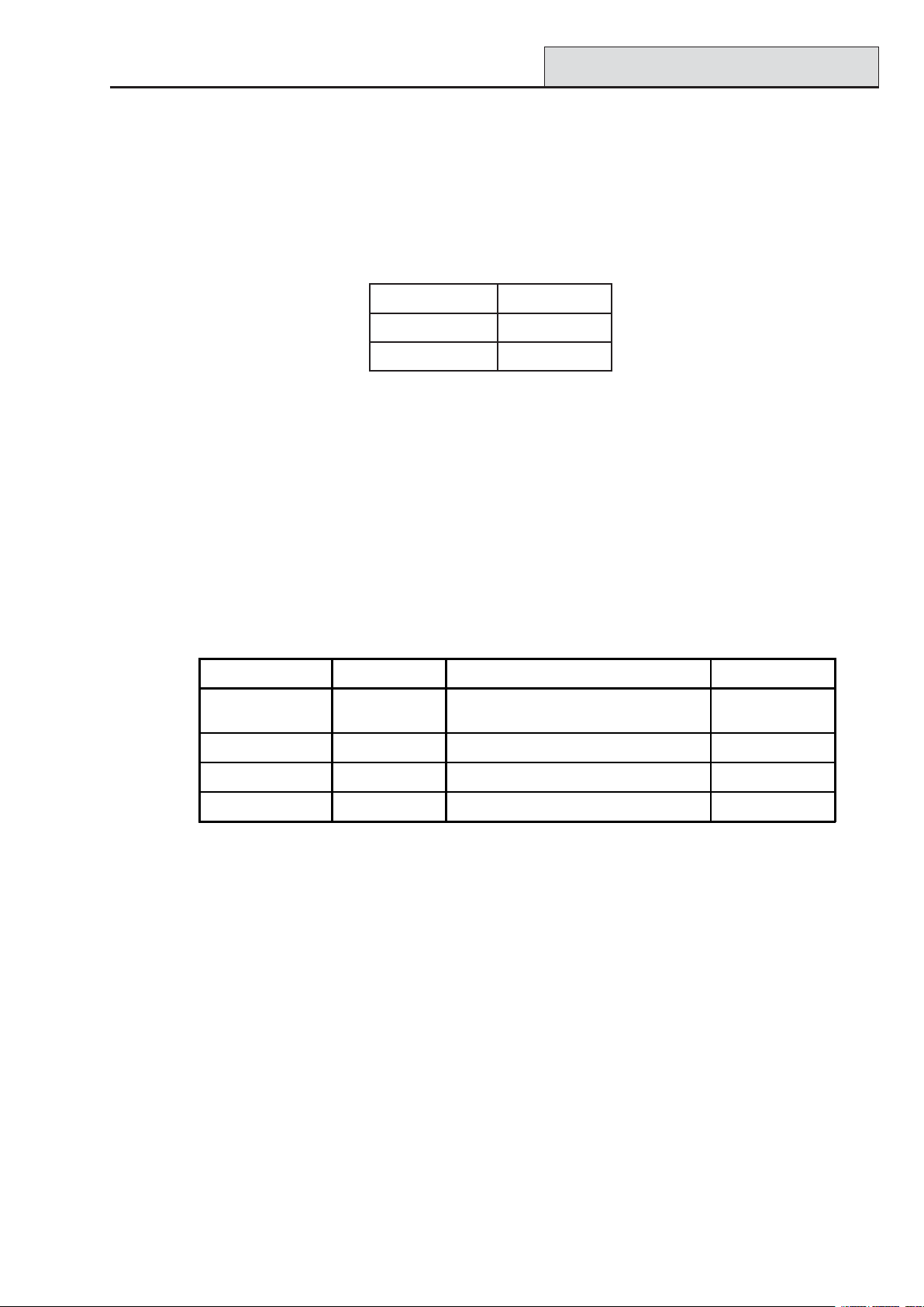
Addressing
The addresses on most peripherals is
set by either jumpers or a rotary
switch. These must be set before the
system is powered up. The table
opposite shows the available peripheral
addresses.
NOTES:
1 A single TouchCenter can be
fitted to each bus line.
2 If RIO 2 on-board is set to line 0
(dip switch 8), then the first
external RIO can use address 1
to give 8 extra zones where
needed.
Peripheral Line GD-48 GD-96 GD-264 GD-520
Mk7 Keypad 1
2
3-4
Mk7 Keyprox 1
2
3-4
To u c h C e n t e r
RIO/PSU 1
MAX/DCM Reader 1
Telecom 1 (E) (E) (E) (E)
RS232 1 (D) (D) (D) (D)
ISDN 1 (C) (C) (C) (C)
Ethernet 1 (B) (B) (B) (B)
1
1
2
3-4
2
3-4
2
3-4
0-2, B-F
-
-
0-2
-
-
0-2
-
-
2-5
-
-
0-3
-
-
Valid Addresses
0-2, B-F
0-2, B-F
-
0-2
0-3
-
0-2
0-3
-
2
2
-5
0-5
-
0-3
0-3
-
0-2, B-F
0-6, F
-
0-2
0-3
-
0-2
0-3
-
22-9, A-F
0-9, A-F
-
0-3
0-3
-
0-2, B-F
0-6, F
0-6, F
0-2
0-6
0-6
02
0-6
0-6
22-9, A-F
0-9, A-F
0-9, A-F
0-7
0-7
0-7
Table 3-2. Galaxy Dimension Peripheral Addresses
3-1
Page 34

RIO
Galaxy Dimension Installer Manual
Connecting the RIO
The RIO can only be connected to the system while engineer mode is accessed. The RS485 (AB) line of the
Galaxy RIO must be wired in parallel (daisy-chain configuration) with the RS485 (AB) line of any keypads
connected to the system. The RIO requires 12 Vd.c. (range 10.5 to 16.0 V) and 40 mA. This can be supplied from the control panel power supply or from a remote power supply if the distance causes a large
voltage drop on the cable.
NOTE: A Power RIO can be fitted in place of a RIO.
Connect the RIO terminals as follows:
+12 V (either control panel, keypad or remote power supply);
–0 V or ground (either control panel, keypad or remote power supply);
A to the A terminal of the previous module (or control panel if RIO is the first on the line);
B to the B terminal of the previous module (or control panel if RIO is the first on the line).
NOTE: If the RIO is the last module on the line, connect a 680 Ω EOL resistor across the A and B termi-
nals.
Configuring the RIO
The added RIO is configured into the system on exiting from engineer mode. If the message XX Mod Added
[<],[>] To View is displayed, the system has recognised that a new module is present. Press the A or B keys
to confirm that the RIO has been added. If this message is not displayed or the RIO is not on the list of added
modules, then the RIO is not communicating with the control panel or has been set to the same address as the
RIO already connected to the system.
The flash rate of the red LED (LED1) on the RIO indicates the status of the communication with the control
panel - refer to the following Table:
etaRhsalFgninaeM
FFO9.0/NO1.0snoitacinummoclamroN
FFOylppus.c.doN
FFO5.1/NO5.1metsysotniderugifnocneebtonsah
FFO2.0/NO2.0metsyshtiwnoitacinummoctsolsahOIR
FFO1.0/NO9.0snoitacinummocroopyreV
OIR
Table 3-3. RIO LED Flash Rates
Zones
The Galaxy RIO has eight programmable zones. These default to INTRUDER. Each zone is Double
Balance monitored with a 1 kΩ resistor in series with the zone detector and a 1 kΩ (1%) resistor in parallel
across the detector switch. The change to 2 kΩ (1%) resistance registers the zone as open/alarm.
3-2
Page 35

Galaxy Dimension Installer Manual
RIO Outputs
RIO Outputs
The RIO has four transistorised outputs. Each output is connected to +12 V via a 3k3Ω pull-up resistor
(refer to Table 3-4). When an output is activated, the load is switched to the negative supply voltage (ground
or 0 V) of the RIO. The current available from each output is 400 mA.
The default functions and pull-up resistors of each RIO output, when connected to a Galaxy are shown in the
following Table:
.oNtuptuOnoitcnuFrotsiseRpu-lluP
1slleB1R
2ebortS3R
3AP5R
4teseR7R
Table 3-4. RIO Output Default Functions
3-3
Page 36

RF RIO
Galaxy Dimension Installer Manual
RF RIO
The Galaxy Radio Frequency (RF) RIO module is an optional add-on to the existing Galaxy product range.
The module acts as an RF receiver for the Ademco 868MHz transmitter range.
Features
The RF RIO contains the following features:
• Support for up to 32 RF zones (dependent upon panel type)
• Support for up to 30 RF keyfobs
• 4 transistorised outputs
Panel Keypad
Panel Keypad
Outputs
Outputs
Outputs
1
1
1
2
2
2
4
4
4
3
3
3
Panel Keypad
BA -+BA - +
BA -+BA - +
BA -+ BA - +
Pull-up
Resistors
Tamper
link
Tamper
Switch
R7 R5 R3 R1
LED1
SW2
SW6
LK1
SW3
Programming
Switch
Connecting the RF RIO
SW1
Processor
Retaining Slot
Rotary
Address
Switch
Figure 3-1. RF RIO PCB Layout
Programming
Keypad
Socket
Rev 1.0
The RS 485 (AB) line of the RF RIO must be wired in parallel (daisy chain configuration) with the RS 485
(AB) line of the keypad connected to it. The RF RIO requires 12 V d.c. (range 10.5 to 16.0 V) and 55 mA.
This can be supplied from the control panel power supply or from a remote power supply if the distance
causes a large voltage drop on the cable.
3-4
Page 37

Galaxy Dimension Installer Manual
Connect the RF RIO terminals in accordance with the following Table:
lanimreTOIRFR...otdetcennoC
+)ylppusrewopetomerrodapyek,lenaplortnocta(V21+
RF RIO (cont’d)
- )ylppusrewopetomerrodapyek,l
A
B
enaplortnocta(dnuorgroV0
ehtsiOIRFRehtfilenap
iOIRFRehtfilenap
)enilehtnoeludomtsrif
)enilehtnoeludomtsrifehts
lortnocehtro(enilehtnoeludomsuoiverpehtfolanimretAehtoT
lortnocehtro(enilehtnoeludomsuoiverpehtfolanimretBehtoT
Table 3-5. RF RIO Connections
Note: If the RF RIO is the last Module on the line, connect a 680 Ω resistor across the A and B terminals.
Outputs
The RF RIO has four transistorised outputs. Each output is connected to +12 V via a 3k3Ω pull-up resistor
(refer to Table 3-6 RF RIO Connections). When an output is activated, the load is switched to the negative
supply voltage (ground or 0 V) of the RF RIO. Each output is capable of supplying 400 mA.
The default functions and pull-up resistors of each RF RIO output, when connected to a Galaxy are shown in
the following Table:
.oNtuptuOtluafeD
noitcnuF
1slleB34R
2ebortS73R
rotsiseRpu-lluP
3AP33R
4teseR32R
Table 3-6. Output Functions
NOTE: The number of pull-up resistors may vary with different hardware revisions.
RF RIO Tamper
Switch SW2 on the RF RIO acts as a tamper if the Tamper Link (LK1) is missing. Removing the lid from the
RF RIO enclosure activates the RF RIO tamper alarm if the system is not in Engineer Mode. The tamper
switch can be bypassed by fitting a 0 Ω link to LK1.
Addressing the RF RIO
The Galaxy RF RIO must be given unique addresses before it is connected to a power supply. This unique
address is selected using the 16-way Rotary Address Switch (SW1). The address selected will act as the
base address for the RF RIO. Subsequent addresses will be
base address + 1, base address + 2, base address + 3. For example:
Base address = 2 followed by 3, 4 and 5.
3-5
Page 38

RF RIO (cont’d)
Galaxy Dimension Installer Manual
Address Ranges
This option allows the programming of the RIO addresses, which are to be simulated by the RF RIO.
For example, if the RF RIO being programmed supports 32 zones (4 RIO addresses), and the base address,
programmed at the hexi-decimal rotary switch is 02, the available addresses would be 02, 03, 04, 05. However, you may want to only respond as RIO addresses 02, 04. The remaining addresses should be disabled
and will not respond to commands from the control panel. The base address is enabled by default. All other
addresses are disabled by default.
Module status on the RF RIO such as lid tamper,will be reported to the panel using the address set on the
rotary switch.
RF RIO Programming
Programming of the RF RIO is achieved by connecting a Galaxy Mk7 keypad directly to the RF RIO at the
Programming Keypad Socket or the Keypad Connector Block. The Keypad is not part of the Galaxy network and must be addressed as 0.
Note: To program RF devices, please refer to RF RIO Module, Installation and Programming
Instructions, (II1-0076) supplied with the RF RIO.
Configuring the RF RIO
The RF RIO is configured into the system in the same way as a standard RIO. Refer to standard RIO instructions for further details.
3-6
Page 39

Galaxy Dimension Installer Manual
Power Supply Unit
Power Supply Unit
The Galaxy Dimension Power Supply Unit is available in 2 variants.
The Galaxy Power RIO consists of a Power Block and a Control Unit that includes an on-board RIO.
The Galaxy Power Unit consists of a Power Block and a Control Unit without the on-board RIO.
WARNING: There are lethal voltages present in the Power Block. Remove mains power from
the Power Block before handling it.
Each variant can be integrated with all Galaxy Dimension control panels. The number of Power Units or
Power RIO’s that can be used on a system is limited by the number of RIO’s that can be added to each panel.
Off-wall
Tamper
OW
LID
TAM P
Bell-Box
connection
Comms
Line
Outputs
+14.5
+12V2
+12V1
A(DO)
0V
B(DI)
OP3
OP2
OP1
TAM P
LK5
F1
F4
0V
F3
0V
OP4
LK4
LK3
LK2
LK1
3
1
1/2
2
HEATSINK
LK10
F2
Control Unit
5/6
3/4
5
6
4
Zones 1-8
13.8
From
0V
14.5
Powe r
0V
LED1
(comms)
LED2
(AC)
BT
AC/F
+BAT
-BAT
Rotary
Address
Switch
SLAVE
E/E
Block
To Control
Unit
Powe r
13.8V
0V
14.5V
0V
BT
AC/F
Power Block
NEUTRAL
LIVE
Mains
Terminal
Block
Header
BAT
AC
PWR
0V
FAULT OP
8
7/8
7
WARNING: The Power Block PCB
is connected to mains voltage. Always
disconnect mains supply for at least
1 minute before removing the box lid.
Figure 3-2. Power Supply Unit
Configuration
The Galaxy Power Supply Unit (PSU) consists of 2 modules, the Power Block and the Control Unit. The
PSU can be connected to the Galaxy Dimension control panel via the RS485 (AB) line. The PSU can be used
in place of a standard RIO to overcome power problems that arise when the additional RIO is fitted distant to
the control panel.
A 6-way jumper lead connects the Power Block to the Control Unit.
The PSU has 8 zones and 4 outputs. Each PSU takes one of the 4 RIO address (2 - 5). Addressing is identical to that described for RIO Modules.
The 4 outputs are switched 0V (0V active). Without the jumper links (LK1-4) fitted, the outputs will float in
the OFF state. They can apply a +12V signal, if required, by fitting the appropriate pull-up jumper supplied.
LK5 will short out the off-wall tamper if it is not used.
The SLAVE and E/E links must be in place for normal operation.
FAULT OP AC: This is an open collector transistor which is normally off. The output is activated by an AC
failure.
FAULT OP BAT:This is an open collector transistor which is normally off. The output is activated by a
Battery Low or Battery Fail condition.
FAULT OP POWER: This is an open collector transistor which is normally off. The output is activated by
low voltage present in +12V1, +12V2 or +14.5V.
3-7
Page 40

Power Supply Unit (cont’d)
Galaxy Dimension Installer Manual
Installation Instructions
The installation and wiring must be performed by a competent engineer. The Galaxy Dimension Power Supply
Unit must be connected to the a.c. mains supply (230/240 Va.c. 50Hz) via a fused connection outlet. The fuse
in the mains outlet must not exceed 3A.
The Galaxy Dimension Power Supply Unit comes installed in the metal enclosure base. The installation procedure of the panel base is as follows:
1. Route the mains cable through the hole on the right hand side of the enclosure base. Securely anchor
the cable to the box using the tie-wrap as shown in the following Figure:
Enclosure
base
Lid Tamper
Microswitch
Control
Unit
Attaching hole
Figure 3-3. Enclosure Base
6-way jumper lead
from power block
to control unit
Keyhole
slot (top)
Powe r
Block
Off-Wall
Tamper
Micro-switch
Terminal
block
Mains cable
Tie wrap
Attaching hole
2. Secure the panel base to the wall using three 1.5" No. 8 round head steel screws through the holes
provided.
The mains cable used must be a three core type (with green/yellow earth insulation) of adequate current
carrying capacity.
3. Connect the mains cable to the mains terminal block as follows:
• blue wire to the terminal marked N (Neutral)
• green/yellow wire to the terminal marked (Earth)
• brown wire to the terminal marked L (Live)
NOTE: No other connections to the mains connector are permitted.
All wiring must be in accordance with local regulations and the installation must conform to EN60950.
4. Power up by applying mains first. This unit can be powered up from the battery by momentarily shorting
LK10. Never leave LK10 connected, as deep discharge of the battery will occur. LK10 is for start-up
only.
3-8
Page 41

Galaxy Dimension Installer Manual
Power Supply Unit (cont’d)
Battery
The minimum capacity battery to supply the PSU is 1x 7Ah. The maximum capacity battery to supply the
PSU is 2 x 17Ah.
Battery Test
A battery test on full load is automatically performed once an hour and during the Engineer Mode exiting
procedure. If the battery voltage falls to 10 V while the Power Supply Unit is running on the battery, then it is
automatically disconnected to prevent deep discharge of the battery.
Specifications
Electrical (based on 34 Ah battery and UK grade 3 compliance)
Input voltage: 230V a.c. (+10%/-15%) @50Hz
Output voltage (nominal): 13.8V & 14.5V
Output current (max): 3.0A
Operating temperature: -10 deg C to +40 deg C
Aux1 & Aux2
Output voltage (nominal): 13.8V
Output current (max): 0.75A each
14.5V Output (French variant only)
Output voltage (nominal): 14.5V
Output current (max): 0.15A (when using this current, the AUX1 & AUX2 currents will
be reduced by an equivalent amount).
Battery charge current (max): 1.4A
Maximum ripple voltage: less than 100mV
Fuses
F1 (14.5V) 500mA - 20mm anti-surge
F2 (Battery) 1.6A - 20mm anti-surge
F3 ( 12V Aux1) 1.0A - 20mm anti-surge
F4 (12V Aux2) 1.0A - 20mm anti-surge
EN50131 Compliance
This product is suitable for use in systems designed to comply with EN50131-6 and PD6662:2004.
Security Grade - 3
Environmental Class - II
Power Supply Type - A
3-9
Page 42

Printer Interface
Galaxy Dimension Installer Manual
Printer Interface Module
The Printer Interface module allows the Galaxy to be connected to a serial printer and the contents of the
event log and the programming details of the system to be printed out. The module is available with either a:
• 25 way sub D type RS232 serial connector (part number A161)
OR
• 6 pin DIN plug (part number A134)
The printer must have a serial interface port. The printer protocol must be set to:
Protocol Setting
Start Bit ON
Stop Bit ON
Word Length 8 Data Bits
Parity None
Baud Rate 1200
Table 3-7. Printer Protocol Settings
3-10
Page 43

Galaxy Dimension Installer Manual
ISDN Module
ISDN Module
The ISDN Module is an optional add-on to the existing Galaxy product range. It connects directly to the
Galaxy RS485 communication bus, allowing signalling and remote servicing over an ISDN network. The
ISDN Module is housed inside the Galaxy enclosure in the same way as the existing Telecom Module.
The ISDN Module supports the following features:
• Full existing Galaxy Telecom Module functionality
• Analogue/digital/X.25 communication
• Support for existing DTMF, SIA, Contact ID and Microtech signalling formats in addition to two
receiver specific X.25 protocols
• Hardware and software line snatch
• Comprehensive line fail detection and reporting
• Two-way communication using B-Channel and D-Channel.
The ISDN Module is allocated keypad address C on line 1 of the panel, and reports itself as Comm Mod 3.
As a result of the addition of the ISDN Module, keypad address C is not available on line 1. If this keypad is
required, the ISDN Module should be removed.
ISDN IN ISDN OUT
Jumper
Links
JP2 JP1
PROCESSOR
PROM
JP3
D22
LED's
D23
12V GND RS485
IMOD 1 Rev 4
Figure 3-4. ISDN PCB Layout
The position of components on the ISDN PCB may vary with different hardware revisions.
Programming the ISDN Module
The ISDN module is programmed from the Galaxy Dimension control panel using menu option
56 - Communications. The menu is allocated as option 3 after the Int. Telecom and Ext. RS232 Modules.
3-11
Page 44

Ethernet Module
Galaxy Dimension Installer Manual
Ethernet Module
The Ethernet Module is an optional add-on to the Galaxy control panel. It is a highly intelligent and compact
module, combining alarm signalling, remote servicing and integrated facilities over Ethernet LAN and/or WAN.
The Ethernet Module connects to 10 Base T Ethernet networks both supporting UDP/IP and TCP/IP
protocols.
The Ethernet module supports the following features:
• Full alarm signalling on SIA
• Microtech protocol signalling with Event Monitoring Software
• Remote servicing via remote servicing software
LED3
Programming
Header
Processor
Engineer
Socket
+
S
-
AB
Line
LED1
SKT1
Processor
LED2
SKT2
Rev. 1.0
Figure 3-5. Ethernet PCB Layout
NOTE: The position of components on the Ethernet PCB may vary with different hardware revisions
Configuring the Ethernet Module
The added Ethernet Module is configured into the system on exiting from engineer mode and is allocated
keypad address 15 (B). If the message XX Mod Added [<],[>] To View is displayed, the system has
recognised that a new module is present. Press the A or B keys to confirm that com 4 has been added. If
this message is not displayed or the Ethernet Module is not on the list of added modules, then the Ethernet
Module is not communicating with the control panel.
The flash rate of the red LED (LED3) on the Ethernet Module indicates the status of the communication with
the control.
Ethernet Communication
The green LED (LED1) is illuminated when the Ethernet Module is connected to Ethernet.
The amber LED (LED2) flashes when the Ethernet Module is sending or receiving data.
For further information regarding the Ethernet Module, refer to Ethernet Module, Installation Instructions
(II1-0080).
3-12
Page 45

Galaxy Dimension Installer Manual
Audio Control
Galaxy Dimension and 2-Way Audio
Introduction
The Galaxy Dimension allows multiple audio channels to be linked to the intruder system in order to provide
audio verification following an alarm activation. This will allow sound from the area of the alarm activation to
be transmitted to the Alarm Receiving Centre with the alarm signal. This can be recorded audio captured at
the time of the activation as well as live audio. Depending on the set-up, it may be possible for the operator at
the receiving centre to talk back to the site. An Audio Interface Module is required to enable audio on the
Galaxy. This allows up to two audio channels to be connected. If further channels are required, the audio
system can be expanded using the MUX modules. Each alarm group on the Galaxy can have one audio
channel assigned to it.
Audio Interface Module
The Audio Interface Module is connected to the Galaxy RS485 line to allow the panel to control the audio
function and connected to the PSTN line to allow it to transmit the audio signals to the Alarm Receiving Centre.
For expansion using MUX modules, the Audio Interface Module has connections for a high speed digital
audio bus in order to connect the MUX modules. Up to three speaker-mic devices, such as the TP800, can
be connected to each audio channel.
The Audio Interface Module acts as the master to a dedicated Audio RS485 line on to which 8 off-board
Mux Modules can be connected.
Telecom
Connect
Jumper lead
RS485
termination
Engineer Header
Audio Bus
RS485
Audio
Bus
Engineer Header
RS485 line
Galaxy
RS485 line
LINE
A
PHONE
B
AB
SPARE
GND
A
B
+12V
GND
A
B
Telecom
Socket
SKT1
LK4
PL6
AUDIO
Debug Header
PL3
GALAXY
LK2
Off-wall Tamper
microswitch
LK3
SW3
Fuse for
+4.5V
Audio Expansion
Header
F1
PL2
CMD 2
TMP 2
SPK 2
MIC 3
GND
+4.5V
CMD 1
TMP 1
SPK 1
MIC 1
NOTE: Audio Expansion
Header is not currently
used - it is for future
product development.
Audio Channel
Terminals (2)
Figure 3-6. Interface PCB
3-13
Diagnostic
LED's
Page 46

Audio Control (cont’d)
Galaxy Dimension Installer Manual
Addressing
The AudioInterface has a fixed module address.
Mounting
the Audio Interface Module can be mounted in two ways:
• above the control panel PCB using a specially designed mounting plate.
• inside a standard RIO box separate from the control panel.
Connecting the Audio Interface Module to the PSTN
The Audio Interface Module must be connected to the Galaxy panel PCB as in the following diagram.
Audio Interface PCB
30 metres maximum from
panel to Audio Interface
LINE
A
PHONE
Galaxy Panel PCB
B
AB
PHONE
LINE
ABAB
Incoming
PSTN Line
Extension Phone
Figure 3-7. Audio Interface connected to PSTN
Connecting Microphones and Speakers
The Audio channels can work with most line-level audio equipment. Microphones must have a pre-amplifier
that delivers audio or can deliver audio at line level (3V peak to peak). The audio card can transmit audio to
speakers with their own amplifier which accepts line level signals. Please see any instructions with the Microphone device regarding the adjustment of sensitivity. The Galaxy Audio system can be used with the following
Honeywell audio devices:
TP800/TP2-800GY: Speaker and Microphone unit
IS215TCE-MIC: PIR detector with built-in microphone
DT7450-MIC: Dual Tech detector with built-in microphone
TP800/TP2-800GY Connection
IS215TCE-MIC/DT7450-MIC
Connection
The following table details the terminal connections
of the TP800 speaker unit to the Audio Interface:
Audio Interface TP800/TP2-800GY
GND VS-
+4.5V VS+
CMD CMD
SPK RML
MIC ECOUT
TMP AP
AP
Link AP to VS to complete
tamper circuit
Audio Interface IS215TCE-MIC/DT7450-
MIC
GND -
12V +
MIC M
GRD G
Table 3-9. Detector Connections to
Audio Interface
Table 3-8. TP800/TP2-800GY
Connections to Audio Interface
3-14
Page 47

Galaxy Dimension Installer Manual
Audio Control (cont’d)
MUX Module
The MUX Module allows four additional audio channels to be connected. It is connected to the RS485
Audio Bus and acts as a slave module to the Audio Interface.
Each audio channel can have three standard speaker-mic devices such as the TP800 connected.
Jumper lead
RS485
termination
Engineer Header
Audio Bus
RS485
Audio
DC Supply
from Master
or from
local PSU
SPARE
GND
A
B
+12V
GND
PL6
AUDIO
Off-wall Tamper
microswitch
LK4
Debug Header
LK3
SW3
Rotary
Address
Switch
Fuse for
+4.5V
SW1
Audio Expansion
Header (for future
product development)
F1
PL2
CMD 4
TMP 4
SPK 4
MIC 4
GND
+4.5V
CMD 3
TMP 3
SPK 3
MIC 3
CMD 2
TMP 2
SPK 2
MIC 3
GND
+4.5V
CMD 1
TMP 1
SPK 1
MIC 1
Diagnostic
LED's
Audi Channel
Terminals (4)
Figure 3-8. Mux Module PCB
Addressing
The Mux Module must be given a unique address before it is connected to a power supply. This address is
selected using the 16-way Rotary address Switch (SW1). Valid addresses are 0 - 7.
Connecting the MUX Module to the Audio Interface
The MUX Module is connected to the Audio Interface via the RS485 Audio Bus. The following table shows
the connections.
Audio Interface
RS485 Bus
GND GND
Audio A Audio A
Audio B Audio B
Table 3-10. Mux Connections
NOTE: The MUX module can either be supplied with DC power from the Audio Interface or from a local
Power Supply Unit (eg Smart). See Figure 3-8.
MUX RS485
Audio Bus
Connecting Microphones and Speakers
The MUX module is connected to microphones and speakers as per the Audio Interface. See table 3-8.
3-15
Page 48

Audio Control (cont’d)
Galaxy Dimension Installer Manual
Using the Audio
Programming Set up
The Audio channels must be mapped to alarm groups using menu 56.7. This allows the Galaxy panel to know
which audio channel to send to the alarm receiving centre following an alarm activation. In this menu, its also
possible to specify which type of alarm events will result in listen-in operation.
In Use
The audio system continuously records the audio from all channels in a 10 second loop. When an alarm
activation occurs, the audio form the specified channel stops recording and the audio from the time of the
alarm is saved, including a few seconds from before the activation of the detector. The panel will dial the
Alarm Receiving Centre normally and transmit the alarm message and then stay on the line to allow the operator to listen to the audio. The Galaxy system will automatically select the specific channel to be transmitted and
play the live audio initially. The operator has three control options using a DTMF telephone keypad;
1: Talk to site
2: Listen to recorded audio from the activated channel
3: Listen to live audio from the activated channel
99: End call
3-16
Page 49

Galaxy Dimension Installer Manual
Optional Software Packages
Remote Servicing Suite
Remote Servicing Suite (RSS) is an advanced PC based application that allows full remote servicing of Galaxy
systems. Functions include configuration and programming, control and diagnostic servicing. RSS also includes
an Event Monitoring application.
Event Monitoring is an advanced, high performance software program that allows a PC to receive and store
detailed event and alarm information from Galaxy control panels.
User Management Suite
User Management Suite is a software program designed specifically for in-house security managers, and
allows access to key features of the Remote Servicing program in order to facilitate:
• Event log copying
• Holiday period changes
• Summer time date change
• User code amendment
SYSTEM ORDER CODE
Remote Servicing Suite Standalone non-dongled R050
Remote Servicing Suite Standalone/Network-dongled R051
User Management Suite Standalone/Network-dongled R053
Table 3-11. Galaxy PC Products and Order Codes
3-17
Page 50

Galaxy Dimension Installer Manual
3-18
Page 51

Galaxy Dimension Installer Manual
GALAXY 264 V6.00
08:58 TUE 22 NOV
1
2
3
A
4
5
6
B
7
8
9
ent
*
0
#
esc
Mk7 Keypad/KeyProx
SECTION 4: KEYPADS
Two types of keypad can be fitted to the Galaxy Dimension: The Mk7 Keypad and the Touch Center keypad.
Both types of keypad are described in this section.
The Galaxy Mk7 Keypad/KeyProx
NOTE: References in the text to the Mk7 keypad also includes the KeyProx in this section.
General
The Galaxy Mk7 keypad/keyProx has the following features:
• a 2 x 16 alphanumeric character backlit display
• 16 backlit push buttons as shown in figure 4-1
• internal horn
• power indicator LED
• Lid tamper
• Off-wall tamper
• Address switch
• RS485 serial connector
Figure 4-1. Galaxy Mk7 Keypad/KeyProx
Power Consumption
The Galaxy Mk 7 keypad/keyProx requires a 12 Vd.c. supply – from the control panel or a remote power
supply. The current consumption of the keypad/keyProx is:
Current Draw
Nominal (backlight OFF) 35 mA 75 mA
Backlight ON 70 mA 90 mA
Maximum Alarm Current 90 mA 130 mA
Mode Mk7 Keypad Mk7 Keyprox
Table 4-1. Keypad/KeyProx Current draw
4-1
Page 52

Keypad Installation
Galaxy Dimension Installer Manual
Wiring the Keypad/KeyProx
A 16-way rotary address switch is used to address Galaxy LCD keypads. The address switch assigns a
hexadecimal address value to the keypad.
NOTE: Any change to the keypad address must be made when the power is disconnected from the
keypad.
Addressing
Addresses are set by means of a rotary switch on the PCB. Each keypad must be assigned a unique address
for its line.
It is possible to add additional keypads at any unused comms module addresses (B, C, D and E) as detailed
in the following NOTE. These must be standard keypads. An engineer keypad can also be used at address F.
NOTE: On Line 1, keypad addresses B, C, D and E are not available if the Ethernet,
ISDN, RS232 or Telecom modules respectively are fitted.
Keypad/KeyProx Installation Procedure
1. To attach the keypad to the wall, the back plate must first be removed from the front plate. To do this,
insert a suitable tool into both openings at the bottom of the keypad and turn the tool gently.
CAUTION: When the keypad is separated make sure that the anti-static precautions are taken
with the keypad pcb to avoid damage from esd (electro static discharge).
Connections to the terminals are:
rotcennoC
slanimreT
A lenapotenilA
B lenapotenilB
+ tupni.c.dV21
– V0
sdapyeKyxalaG
Table 4-2. Keypad/keyProx Terminal Connections
2. Use the backplate as a template, then mark the locations for the three attachment screws in the
required position.
3. If it is a new installation, use the keyhole slot at the top of the backplate and the two elongated
holes at the bottom. If replacing an existing Mk3 keypad with a Mk7 keypad, use the keyhole
slot at the top of the backplate and the two knockout holes at the bottom. This means that you
can use the existing holes in the wall, whist keeping the backplate in the same position.
4. If you are using a wall-run cable for the keypad (A, B, +12V, 0V) position the cable behind the
back plate in the cable channels provided. The cable can be run in from either the top or the
bottom of the back plate. Use a sharp tool to remove the plastic from the top or the bottom of the
cable guides on the back plate skirting.
CAUTION: Use of any screws other than No. 6 Pan-head can damage the keypad
mouldings.
5. Make sure that the keypad wiring is fed through the large opening on the keypad backplate, then
position the keypad base on the wall and attach it securely with the three No. 6 Pan-head screws.
4-2
Page 53

Galaxy Dimension Installer Manual
Keypad Installation (cont’d)
6. If an off the wall tamper is required, using a No. 6 Pan-head screw, secure the sacrificial wall
tamper, indicated in Figure 4-2, to the wall. Make sure that the tamper knockout is still
connected to the backplate moulding.
7. Connect the A, B and power wires to the correct terminals of the removable, four-way connector
block.
cable
channel
cable
stowage
area
elongated
hole
aperture
keyhole slot
+
B
A
4-way
connector
aperture
sacrificial
wall
tamper
knockout
-
hole
Figure 4-2. Galaxy Mk7 Keypad/KeyProx Backplate Installation
8. Make sure that the power is disconnected then set the keypad to the required address using the 16
way rotary switch on the PCB.
9. To re-assemble the keypad, connect the four-way connector block onto the pins on the keypad
PCB. Attach the keypad front plate to the back plate by inserting the two clips on the top of the
keypad front plate into the two apertures at the top of the keypad back plate, then gently push the
bottom of the keypad front plate into the back plate until it snaps securely into place. Ensure the front
and back sections of the keypad are securely fixed at all points of the keypad perimeter.
Note: The keypad door can be re-orientated to allow opening from either the left or right-hand
sides. However, fitting or removal of the door must only be done when the front plate is
detached from the back plate. Attempting to remove or install the door, when the keypad is
assembled, may cause damage to the keypad mouldings.
4-3
Page 54

Adding/Removing Keypads
Galaxy Dimension Installer Manual
Volume Control
Where fitted, the Mk7 keypad/keyprox has a volume control switch marked VOL at the bottom right-hand
corner of the pcb. Make sure the keypad/keyprox is powered up and adjust to the desired volume (+ or -)
for buzzer functions. Refer to Appendix F for keypad/keyprox part numbers with volume control function.
Adding a Keypad/KeyProx to the System
When adding a keypad to an existing system, the following points must be considered:
1. Ensure that the keypad to be added has a unique address from the other keypads on the system.
2. Ensure that the keypad has a valid address.
3. Connect the keypad to the system - refer to the Keypad Installation Procedure.
Note: A new keypad can only be configured into an existing Galaxy system from engineer mode.
4. Access engineer mode.
5. Connect the RS485 (AB) line of the keypad in parallel with the RS485 (AB) line of the
existing keypads.
6. Connect + and – terminals of the keypad to a power supply.
7. Exit engineer mode - engineer code + esc:
8. The Mk7 keypad displays the message 1 MOD. ADDED — esc=CONTINUE. Press the esc
key; the keypad returns to the unset banner.
NOTE: If this message is not displayed, the keypad is not communicating with the control panel and has not
been configured into the system. In this case all connections and addresses should be rechecked.
NOTE: If adding a keyProx to the system, the message 2 MOD ADDED will be displayed to indicate that
both a keypad and MAX have been added to the system.
9. The keypad is now configured into the system.
Removing a Keypad/KeyProx from the System
A keypad can only be removed from an existing Galaxy system from engineer mode
1. Access engineer mode.
2. Disconnect the keypad.
3. Exit engineer mode. The message 1 MOD. MISSING — [<],[>] to View is displayed
4. Press the A or B key. The message KEYPAD XX —
5. Press the
returns to the unset banner.
NOTE: If removing a keyProx from the system the message 2 MOD MISSING is displayed to indicate
both a keypad and MAX have been removed from the system. Each should be removed separately
by pressing the * key twice.
key to acknowledge and accept that the keypad has been removed. The keypad
4-4
=REMOVE MODULE is displayed.
Page 55

Galaxy Dimension Installer Manual
Keypad Operation
Self Diagnostics
The keypad has a self diagnostic feature that is used to test the operational status of the inputs and outputs of
the keypad.
The test is started by disconnecting the power from the keypad, then reapplying the power while pressing the
ent key. The test routine commences immediately. Each test last approximately four seconds. The test is
terminated by removing the power.
• Keypad address is displayed
• Keypad buzzer is activated and a bell symbol is displayed.
• Power LED is illuminated and an a.c. ( ) and LED ( ) symbol is displayed.
• Keypad keys are displayed. Each key press is confirmed by the buzzer sounding and the key display
being highlighted.
• To return keypad to operational mode remove and reapply power.
Keypad/KeyProx Operation
Number Keys
The number keys are used to enter the Personal Identification Number
1
4
7
2
5
8
3
6
9
0
The number keys are also used, once access to the system has been gained, to select and modify options.
(PIN) which identifies users to the Galaxy and permits access to the system
options. The PIN Code is a 5 or 6 digit number.
edoCtluafeD
reenignE332211
resUetomeR012345
reganaMretsaM54321
noitasirohtuA12345
Table 4-3. Default Codes
View Keys
These keys are used to initiate the setting of the Galaxy
A
B
Pressing the A or B key immediately after a valid PIN has been entered starts
one of the routines for setting the system. The A key initiates the full setting of
the Galaxy. The B key starts the part setting routine.
Once the system has been successfully accessed the A key can be used to
step forward through the Galaxy menu options and the B key to step backwards.
The A and B keys can also be re-programmed for different functions.
Enter Key
ent
The ent key is used to:
• Access the menu options
• Confirm the programming selections
4-5
Page 56

Keypad Operation (cont’d)
Escape Key
The esc key cancels any modification made to the current option and returns
esc
to the previous option level. Successive pressing of this key returns the user
to the banner display.
The esc key also aborts the setting routine if pressed during the exit time.
Hash Key
The # key is used :
• as a toggle key, which enables or disables the programming features of
the Galaxy options, for example, enabling the OMIT attribute of a zone,
#
• to give additional information on the programming options, for example
pressing the # key while in option 22=DISPLAY LOG shows details of the
user number, descriptor and keypad used to cancel alarms or unset the
system.
• to activate the Duress and PA outputs; enter a valid user code followed by two
presses of the # key, then the ent key to activate the duress alarm.
Galaxy Dimension Installer Manual
Star Key
*
The º key is used:
• to correct or erase PINs in the CODES option and alpha-numeric
descriptors in the TEXT option,
• to start printing from the current event when viewing option
22=DISPLAY LOG.
• to display the set status of the groups. When Show Status (refer to option
58.6=KEYPADS.Show Status) is enabled, pressing the º and # keys simultaneously
when the normal banner is displayed indicates the group set status.
R = Ready to Set (all active zones in group closed)
F= Faulted (at least one of the active zones in the group is open)
S = Set
P = Part Set
L = Locked Out
- = Group not assigned to keypad
Note: The Show Status indicates the set conditions of groups when the system is set
(keypad blank) or unset (normal banner). Show Status does not operate while
engineer mode is accessed.
Pressing the º and # keys again toggles the display to show the status of the groups
individually. To move between each groups, press the º and A or the º and B keys
simultaneously.
Pressing the º and # again returns the keypad to the banner display.
4-6
Page 57

Galaxy Dimension Installer Manual
Keypad Operation (cont’d)
Multiple Group Systems
The larger Galaxy systems have more than eight groups; these are displayed on the keypad in blocks of eight
groups. Press the A or B key to display each of the group blocks.
Power LED
The green power LED indicates the status of the a.c. power supply and the stand-by battery.
DELrewoPsutatS.c.asutatSyrettaBsutatSesuF
NOKO.c.aKOyrettaBKOsesuF
hsalfwolSliaF.c.aKOyrettaBKOsesuF
hsalFkciuQKO/
liaF.c.awoLyrettaBnwolbesuF
Table 4-4. a.c./Battery Status Indicator
NOTE: It is advised that a suitably rated stand-by battery is fitted to the system in order to provide contin-
ued protection in the event of a mains failure. The battery is not included.
Display
The Galaxy Keypad/KeyProx have a 2 x 16 character backlit display used to display programming information and system status.
GALAXY 264 V6.00GALAXY 264 V6.00
GALAXY 264 V6.00
GALAXY 264 V6.00GALAXY 264 V6.00
08:58 TUE 22 NOV08:58 TUE 22 NOV
08:58 TUE 22 NOV
08:58 TUE 22 NOV08:58 TUE 22 NOV
4-7
Page 58

Keyprox
Galaxy Dimension Installer Manual
The Galaxy KeyProx
General
The KeyProx is a standard Mk7 keypad with a proximity card reader built in to the lower right corner. This
allows users to set and unset the system, using proximity cards, rather than a pin.
NOTE: The keyProx is not intended for use as a door control unit. Installation and wiring of the KeyProx is
identical to the Mk7 keypad.
Addressing
Both the KeyProx and reader share a common address, set by the rotary address switch.
An address must be chosen which will be valid for both the keypad and MAX.
Please note that in order for the reader to operate, MAX mode must be enabled in the panel programming,
(option 63.2.1 = Options.MAX.MAX Mode). The MAX addressing function in option 63.2.2 = MAX
Address, is not required for keyprox units.
Operation
The operation of the KeyProx is identical to the Mk7 keypad. The proximity reader is seen by the panel as an
on-line MAX reader. It is programmed in exactly the same way with the exception that it does not require to
be addressed (this being set already by the rotary switch).
Card Types
The KeyProx can read standard ASK (Amplitude Shift Keying) type cards up to 34 bit. A self learn feature is
incorporared into the KeyProx to aid in card programming.
For further details on how to set up user cards, to set and unset the system, refer to Option 42 - Codes.
4-8
Page 59

Galaxy Dimension Installer Manual
TouchCenter
The Galaxy Dimension TouchCenter
General
The Galaxy Dimension TouchCenter connects to the RS485 data bus of the Galaxy Dimension panels. The
TouchCenter combines a clear graphical display with simple touch-screen control, providing an easy user
interface.
Mk7 Keypad
Interface button
Figure 4.3 Homepage Screen
EMERGENCY
button
TouchCenter Installation Procedure
1 Remove the mounting plate from the TouchCenter by pushing it towards the bottom of the keypad.
2 Locate the mounting plate over the mounting surface such that the opening of the mounting plate is
aligned with the cable.
3 Pass the cable through the opening of the mounting plate.
4 Secure the mounting plate to the mounting surface using the four screws supplied.
5 Connect the wires to the TouchCenter terminals as per the following table:
Galaxy Terminals TouchCenter Terminals
AG
BY
GND -
+12V +
Table 4-5. TouchCenter Terminal Connections
6. Mount the TouchCenter to the mounting plate by locating the four elongated holes over the locations on
the mounting plate and pushing down until it snaps into position.
4-9
Page 60

TouchCenter (cont’d)
Galaxy Dimension Installer Manual
Configuring a TouchCenter
To configure a new TouchCenter do the following:
1 - Set an Address
On first power up, the TouchCenter will immediately prompt for a bus address. This should be any valid
address that is not shared with any other keypad on the same RS485 (AB) Line. The default address is
usually acceptable.
Or
If the address has previously been set and the address prompt does not appear, re-power the keypad and
within five seconds of power up, press the Console mode button then press the ent button to change the
address.
2 - Register with the Control Panel
Once the address has been selected, the control panel must be repowered or, if another keypad is already
configured, exit from Engineer mode and the new TouchCenter will be registered.
The Home Page will be displayed and the keypad is ready to use.
NOTE: Refer to the control panel literature for valid addresses. One TouchCenter can be fitted to each
Galaxy RS485 line.
Set-up Menu
The TouchCenter has a number of configuration settings which are set up directly within the keypad. To
access these settings, the TouchCenter must be in communication with the Galaxy Panel. The panel must be in
Engineer’s mode. Proceed as follows:
1. From the home screen press the SECURITY button and then enter the Authorisation code. This is the
Engineer PIN of the control panel. The Security screen is displayed.
2. Press the MORE CHOICES button to enter the More Choices screen.
3. Press the KEYPAD SETUP button to enter the Setup screen.
4. Press the KEYPAD TEST button.
From this screen, the following options are available;
Self Diagnostics
A series of diagnostic tests are provided that allows verification of correct operation of the TouchCenter and
its connection to the Galaxy system. There are three diagnostic tests:
• LCD Display Test
• Audio Test
• LED Test
Address
This allows the RS485 address to be changed. A change to this will require reconfiguration of the
TouchCenter with the control panel.
4-10
Page 61

Galaxy Dimension Installer Manual
TouchCenter (cont’d)
TouchCenter - Operation
For general operation refer to the on-screen information and to the separate user’s guide.
For programming of the control panel, all options can be accessed via the virtual terminal mode, that emulates
a standard installer keypad. To access the terminal mode, press the terminal keypad icon in the lower left
corner of the Home Page.
Specifications
Mechanical
Dimensions:
Width: 182 mm
Height: 128 mm
Depth: 34 mm
Weight: 500g (approx)
Electrical
Operating Voltage: 10.5 to 14V DC
Current Drain:
Backlight OFF, Sound ON: 120mA
Backlight ON, Sound OFF 150mA
Backlight ON, Sound ON: 170mA
Standby: 105mA
4-11
Page 62

Galaxy Dimension Installer Manual
4-12
Page 63

Galaxy Dimension Installer Manual
Access Control
SECTION 5: ACCESS CONTROL
Door Control Modules (DCMs) can be added onto the Galaxy bus lines to add fully integrated access control. Each DCM allows two Wiegand readers to be connected to control two separate doors; each door with
an exit button or one door with an entry and exit reader..
Group Based Access Control
Access control works best when Group Mode is enabled. Each access reader can then be programmed to
control access to a particular group (or area/subsystem) within the building. Only users who have access
privileges to that group will be granted access via that reader.
User and Access Templates
Every user on the system must be allocated an access template. An access template is a list of groups and
time schedules that will dictate which groups a user is able to gain access to and also the times that the user
can gain access. This method means that if there are multiple doors leading into one group or area, then a user
will be given access to all those doors in one move. This reduces programming time and complexity.
The Access Template to be used for each user is chosen within each user’s options in menu
42.1.11.= Template. There are multiple access templates available (dependant on panel variant) and each
one is fully customisable.
Access Templates are programmed in menu 45.7 = Access Templates. In each Access Template each
group on the system must be allocated a time schedule as required. If no schedule is allocated to a particular
group (default) in the list then users will have full access through any doors leading to that group. When a
schedule is allocated, access will be granted during the OFF periods of the schedule and denied during the
ON periods. Time schedules are programmed in menu 65 = Timers .
Time Schedules
A Time schedule is a weekly list of on and off times and can be used to control the security of any object that
it is assigned to. When a timer is ON it forces a secure state (system set, access denied etc). When a timer is
in the OFF state, it causes an un-secure state (system unset or access allowed etc). Up to 28 on or off times
can be programmed into each weekly schedule. Up to 67 schedules are available dependant on panel variant.
For each time schedule, it is possible to allocate one of 32 Holiday Calendars. A Holiday Calendar is a list of
20 holiday periods, each with a start and end date, which suspend normal timer operation. During a holiday
period, one of two things can happen.
1. The timer is frozen in its current state (on or off) and will resume operation from the next event when the
holiday period finishes.
2. An alternate time schedule can be appointed to be used for the duration of the holiday period.
5-1
Page 64

Access Control (cont’d)
Galaxy Dimension Installer Manual
Door Control Module
Door Control Modules (DCMs) can be added onto the Galaxy bus lines to add fully integrated access control. Each DCM allows up to two Wiegand readers to be connected to control two separate doors; each door
with an exit button or one door with an entry and exit reader.
Shield
U EXT
0V
D0/
CLK
D1/
DATA
LED
Red
LED
Ye l
LED
Grn
BUZ
BC
0V
EC
RS485
B
A
LED 2
(power)
LED 1
(comms)
0V
BUS1/2
0V
Data
0V
Shield
U in
Shield
U EXT
0V
D0/
CLK
D1/
DATA
LED
Red
LED
Ye l
LED
Grn
BUZ
BC
0V
EC
* 2
! "
#
$% &$ %'
$( &$ ('
)*$
)*$
)*$ +
,,
- .
#
/*
Wiegand
Reader
Inputs
DC
0V
FC
NC
C
NO
$
TC 0V
/
)
"!
3
$
ON
1
2 3
4 5
6
7 8
"!
DC
0V
FC
NC
NO
$(1 "!
$
#
0
& '
-
C
-
Figure 5-1. Door Control Module PCB
NOTES:
1. If only one door is being connected, then always use the connections for Door 1 (Left Side) and
terminate the inputs with a 1K resistor.
2. When door readers are being connected for entry and exit to the same door, then connect the entry
reader to Door 1 and connect the exit reader to Door 2.
5-2
Page 65

Galaxy Dimension Installer Manual
Access Control (cont’d)
Inputs
The DCM includes the following sensing inputs:
Door Contact (DC)
This input is a normal alarm zone input that has the same functionality as a
normal security zone type. It uses normal 1k/2k double balanced zone
wiring.
Request To Exit Contact (EC)
This input is a normally open contact. When activated it will allow
the door to unlock for the programmed duration. Additionally, the
door can be held unlocked indefinitely by holding the EC closed. In
this case, the relay activates only for the programmed duration but
the door propped alarm is held off. This can be achieved, for
example, by using a keyswitch wired in parallel with the normal EC
button.
Normally
Closed
1k
Normally
Open
0V
0V
DC
1k
Door Contact Wiring
EC
Request to Exit
Contact Wiring
Function Contact
This uses normal 1 k/2 k double balanced zone wiring. It
has the function of initiating a pre-programmed menu option
following a valid card. The normal use is to activate the
setting procedure via the reader but any menu option can
be programmed.
Tamper Inputs
The tamper circuits for both readers should be wired to the same tamper
terminals on the DCM. The two circuits are wired in parallel, each with its
own series resistor as follows:
The reader tamper is double-balanced.
• Reader 1 - 5.6kΩ
• Reader 2 - 12kΩ
Connecting a Wiegand Device
Normally
Closed
5k6
12k
1k
0V
Normally
Closed
0V
FC
1k
Function Contact Wiring
TC
Tamper Contact Wiring
A standard Wiegand card reader or keypad can be connected to the DCM.
The keypad can operate in 4-bit and 8-bit burst mode.
Wiegand Reader Inputs
The wires from the Reader are connected to the Wiegand Reader Inputs (see
Figure 5-1). Refer to separate Reader instructions for method of wiring the
Reader to the DCM.
5-3
Page 66

Access Control (cont’d)
Buzzer Output
This activates the buzzer on the reader to indicate card read, access granted and card rejected. The output is
open collector and can switch up to 100 mA.
LED Output
LED output 3 is used to drive a reader LED. It is open collector and can switch up to 100 mA. LED outputs
1 and 2 are not used. The LED gives a visible indication on the reader of card read and access granted.
Relay Output
This is a relay output which is activated upon any valid card read or RTE button operation in order to temporarily unlock the door. The relay can switch up to 1A @ 30V AC.
Galaxy Dimension Installer Manual
Installation and Mounting
The DCM can be supplied installed in a standard plastic RIO box or within a Power RIO box.
Mounting the RIO Box
1. If necessary, remove the DCM PCB from the box to allow access to the screw holes.
2. Fix the base to the mounting surface, using the screw holes provided.
3. All cables must be brought into the enclosure base via the cable entry points. There are six cable entry
holes for the entry of alarm cables.
4. Attach the RIO box lid with the four thread forming screws provided.
Mounting the Power RIO Box
The DCM is mounted above the control PCB on a mounting plate.
1. Remove the screws securing the left hand control PCB to the box.
2. Fit the four mounting pillars supplied with the kit in place of the PCB screws.
3. Fit the mounting plate to the pillars and secure using the screws removed from the PCB.
4. Attach the DCM to the mounting plate using the plastic clips supplied.
Wiring the Reader to the DCM
The wires from the Reader are connected to the Weigand Reader Inputs (see Figure 5-3). Refer to separate
Reader instructions for method of wiring the Reader to the DCM.
Addressing with DIP Switches
The DCM must be given a unique address before it is connected to a power supply. The DCM can be addressed with the DIP switches. The addressing works in a binary mode. The following table shows each DIP
switch with related address number. Switches 4 to 8 must be left in the off position.
5-4
Page 67

Galaxy Dimension Installer Manual
Address 1 2 3 4-8
0 OFF OFF OFF OFF
1 ON OFF OFF OFF
2 OFF ON OFF OFF
3ONONOFFOFF
4 OFF OFF ON OFF
5ONOFFONOFF
6 OFF ON ON OFF
7 ONONON OFF
Access Control (cont’d)
Switch
Table 5-1. DIP Switch Addressing
Connecting the DCM to Galaxy System
The DCM must be wired to the Galaxy RS485 (AB) line in parallel (daisy-chain configuration). The DCM
requires 12V d.c. This can be supplied from the control panel power supply or from the Power RIO when
mounted inside the Power RIO box.
See Figure 5-1 for a diagram of the connections.
NOTE: If the DCM is the last module on the line, connect a 680 Ω EOL resistor across the A and B
terminals.
Configuring the DCM
The added DCM is configured into the system on power up of the control panel or when exiting from engineer
mode. The flash rate of the green comms LED (LED1) on the DCM indicates the status of the communication
with the control panel. A short flash once per second indicates good communications.
LED 2 when lit indicates that there is power to the DCM.
5-5
Page 68

Access Control (cont’d)
Galaxy Dimension Installer Manual
Specifications
Physical
Weight (RIO): 270g approx.
Dimensions (RIO Box mm): 150 wide x 162 high x 39 deep
For additional weight and Dimension when housed within a Power RIO enclosure, please see the Power RIO
documentation.
Electrical
Operating voltage range: 10.5V to 15V
Current draw, Typical: 40mA Typical
Current draw, Maximum
(2 readers): 130 mA
Compliance
This product is suitable for use in systems compliant to EN50131-1: 2006, EN50133-1 and PD6662.
This product has been tested for compliance to EN50131-3 and EN50133-3 by CNPP.
Security Grade: 3
Environmental class: II
5-6
Page 69

Galaxy Dimension Installer Manual
Access Control (cont’d)
MAX
The MAX3 is a proximity reader access control device for a single door, which can also be used for setting
and unsetting of your alarm control panel. The MAX3 can be configured in one of two ways:
3
Standalone
In this configuration the MAX3 can be used for either door control or alarm system set/unset control, by either
connecting the internal relay output to a door lock or external relay. When in standalone mode the MAX3 is
programmed and operated using the MAX3 proximity cards or tags.The proximity cards and tags each have
unique ID numbers and must be identified to the MAX3 before being used to operate the system. The MAX
memory can store up to 999 ID numbers, including at least three reserved for Masters. Once programmed,
the ID number of the tags and cards are stored indefinitely in the MAX3 memory until voided (removed) or
erased. Removing power from the MAX3 does not erase the programming memory.
Note : The MAX3 defaults to standalone mode. It can be configured to on-line mode directly from the
Galaxy Dimension control panels.
On-line
The MAX3 can operate in on-line mode, with the Galaxy Dimension control panel range, as a completely
integrated module on the system. In this configuration the MAX3 can be used for both door control and alarm
system set/unset control with complete user traceability stored within the Galaxy control panel.
For detailed instructions on how to programme the MAX3 onto the system in on-line mode refer to Option
69.2=MAX.
3
Installing the MAX
3
MAX3 Pack
Your Max3 pack contains the following:
• Max3 proximity reader *
• Max3 drilling template
• Max3 installation instructions
• Surge suppressor
* The MAX3 is supplied with 3 metres of 12 wire E111235 AWG cable which is fixed and sealed through a
keyhole opening on the rear surface of the MAX3 .
Mounting the MAX
To mount the MAX3 use the step by step diagrams provided with the drilling template.
The drilling template should be used as an aid to locate the holes required to secure the MAX3 and insert the
connection cable.
The MAX3 comes with an infra red lid tamper. The tamper is activated when the lid is removed from the
MAX3 unit.
3
5-7
Page 70

Access Control (cont’d)
Galaxy Dimension Installer Manual
Wiring the MAX
3
The MAX3 unit can be connected to the control panel in
one of two ways depending upon whether it is being
used in an on-line or standalone configuration. The
diagram opposite provides details for both configurations. The MAX3 relay is configured in either the NC or
NO configuration depending upon the variant purchased
(MX03 - Normally Closed, MX03-NO - Normally
Open).
NOTE: Fitting of an external relay may be required
when using AC powered locks.
Supply Volts 12V dc
Quiescent Current 35 mA
Maximum Current 50 mA
Maximum Switching Current 1A @ 30V dc max.
Security Grade 3
Environmental class IV
Weight (boxed) 267 gm
Dimensions (box) 185x120x48 mm (LxBxH)
Table 5-2. MAX3 Specifications
Galaxy Panel Compatibility
Galaxy Dimensi on
Series
Galaxy 2 Series V1.4 or later
All
)
)
-*
-
)"#
+,
.*
#
-
"-
!"#
'/ !"#
'( )
)
"#
#* !
$%& !
$%&- !
$%&
$%&-
'/
)( $%&
-
0/
Galaxy 8-512 Series V2 or later
Table 5-3. Panel compatibility
Figure 5-2. Connection diagram
1 = Read (Amber)
2 = Open (Green)
3 = Closed (Red)
4 = Nightlock (Red)
5 = Add (Red)
6 = Void (Red)
7 = Program (Red)
MAX
x
P
3
Figure 5-3. MAX3 LED’s
5-8
Page 71

Galaxy Dimension Installer Manual
Access Control (cont’d)
Configuring a MAX3 Reader into the System
NOTE: MAX3 readers can only be configured into the Galaxy system from engineer mode.
1. Connect the MAX3 to the Galaxy control panel as per the instructions given in Figure 5-1.
2. Access engineer mode.
3. Ensure that the Mode is enabled (option 69.1.1 = Access Control.Mode.Enabled).
4. Assign the MAX3 reader as either On-Line or Stand-Alone using option 69.2.1 = Access
Control.MAX.MAX Address:
0 = On-Line: The MAX3 is fully integrated with the Galaxy system and communicates via the AB line,
sharing system resources and facilities.
1 = Standalone (default): The MAX3 operates as an entirely independent unit. The Galaxy does not
monitor the MAX3 for alarms, tampers or power failure.
5. Press the ent key; the Galaxy panel may prompt (depending on model) for the AB line (1 – 4)) that is
to be searched; select the line and press the ent key. The Galaxy searches for the MAX3 with the
highest address. New MAX3 readers are addressed as 8 (standalone) by default.
6. Only if adding a new MAX3 reader: On locating the MAX3 address, the keypad prompts for the
OPERATING MODE of MAX3 to be assigned: select 0 = On-Line or 1 = Standalone as required
and press the ent key.
When 0 = On-Line mode is selected, the keypad displays the current address of the MAX3 and the
range of valid addresses. Enter the new MAX3 address and press the ent key; the Galaxy then repro
grams the address of the MAX3. The keypad indicates the old and new MAX3 addresses and the
status of the reprogramming.
NOTE: It is recommended that when adding a reader, it is addressed as the lowest available number on the
line.
7. When the reprogramming is complete the MAX3 bleeps, the LED’s on the MAX3 switch off and the
keypad display returns to 1 = MAX Address.
8. Exit engineer mode - engineer code + esc: the keypad displays the message 1 MOD. ADDED esc=CONTINUE. LED 2 on the MAX3 reader switches on. Press the esc key; the keypad
returns to the unset banner.
If this message is not displayed, the MAX3 reader is not communicating with the control panel
and has not been configured into the system (LED 2 does not switch on).
NOTES:
1. The MAX3 reader will not operate until engineer mode is exited and the reader is configured into the
system.
2. All MAX3 doors must be closed, otherwise engineer mode cannot be exited.
9. The on-line MAX3 reader is now configured into the system.
5-9
Page 72

Access Control (cont’d)
Galaxy Dimension Installer Manual
Removing a MAX3 Reader from the System
On-Line Mode
1. Access engineer mode.
2. Disconnect the MAX3 reader (AB line and power).
3. Exit engineer mode.
4. The message 1 MOD. MISSING — [<],[>] to View is displayed.
5. Press the A or B key.
6. The message MAX XX —º =REMOVE MODULE is displayed.
7. Press the º key to acknowledge and accept that the MAX3 reader has been removed. The keypad
returns to the unset banner.
Operating Instructions
The MAX3 must be presented with a valid user card to allow access. Opening the door without presenting a
valid card activates a door forced alarm at the panel; the buzzer sounds and LED 2 flashes until the door is
closed.
Activating the egress switch allows the door to be opened without activating an alarm when no card has been
presented to the MAX3.
1. Ensure that LED 3 is on and all other LEDs are off.
2. Swipe the MAX with a standard user or nightlock access user card. LED 3 switches off and LED 2
switches on for the programmed Open Timeout.
3. Open the door while the LED 2 is on and access the area.
4. Close the door; LED 2 switches off and LED 3 switches on. The door must be closed within the programmed Close Timeout; if the door remains open longer than this, an alarm is activated.
Card-Held Function
The MAX3 or DCM card can be assigned a single menu option (refer to option 42.1.8 = CODES.User
Codes.MAX Function). To activate the function assigned to the MAX3 or DCM card, hold the card in front
of the reader for three seconds; all of the LEDs switch on. If a keypad has been assigned to the MAX function then it displays the details of this option. If no keypad is assigned, pressing a key on any of the keypads
assigned to a common group to the user displays the card-held function.
Card-Held System Setting
If the MAX3 or DCM card is assigned one of the setting options (option 12, 13, 14 & 16 – 19), the card-held
functions starts the setting procedure for the groups assigned to the card.
NOTE: If Group Restriction is assigned, then only the groups that are common to both the MAX3 reader
and the MAX3 user are set/unset
To unset the system using the MAX3 or DCM card, swipe the reader with a valid card. The reader beeps. All
of the groups assigned to the card are instantly unset.
5-10
Page 73

Galaxy Dimension Installer Manual
Access Control (cont’d)
MAX3 Log
The Galaxy system has a panel dependent event log for recording the MAX3 activations. This log is shared by
all readers on the system and operates on a first-in-first-out basis for overwriting events when the log is filled.
To display the events in the MAX3 log select option 25 = ACCESS DOORS; use the A or B keys to select
the required MAX3 address then press the ent key. The first event that occurred on the selected MAX3 is
displayed along with details of the time, date and MAX3 number.
To view the log press the A key to move forward in time through the events or the B key to move backwards.
Press the esc key to return to the MicroMAX address display. To view the log of another MAX3, use the A
or B key to select the required address. To escape from the Access Doors option press the esc key.
Time and date
of event
MAX3 user number Event type
MAX3 Events Print-Out
The MAX3 events can be printed out as they occur to an on-line printer. To print the MAX3 events ensure
that option 51.27 = PARAMETERS.On-Line Print is enabled. Select option 51.28 =
PARAMETERS.On-Line Level and enter 2 to print out all system events including the MAX3 events or 3
to print out only the MAX3 events.
NOTE: A serial printer must be connected to line one of the Galaxy panel and the printer must remain on-line
(ready to print) at all times.
02:25 SUN 22 OCT02:25 SUN 22 OCT
02:25 SUN 22 OCT
02:25 SUN 22 OCT02:25 SUN 22 OCT
USR032 ValidUSR032 Valid
USR032 Valid
USR032 ValidUSR032 Valid
Downloading the MAX3/ DCM Log
The MAX3/DCM event log can be downloaded to Remote Servicing by using the MAX/DCM Log copy
option in Remote Servicing.
5-11
Page 74

Access Control (cont’d)
Galaxy Dimension Installer Manual
Dual Access Cards
If a user’s card number is assigned a *, then the card becomes Dual access. This means that it will not open
the door on its own; it needs another PIN or card as well. (see option 42 = Codes for programming).
Dual Focus (Card Held)
If a card has a # assigned to the number, then any card-held function will only work in conjunction with the
PIN from the same user, provided that the PIN has a # assigned also. The Dual Focus function will work in
either order, but if the card is presented first, it will simply enable the PIN to gain access to the normal menu
(see option 42 = Codes for programming).
Timed Anti-Passback
When the Timed Anti-Passback feature is enabled, it will prevent more than one use of any particular card at a
particular reader within a given time period. See option
69.2.2.6 = Access Control.MAX.Max Parameters.Anti-Passback for programming details.
A forgiveness function is available to clear all or particular antipassback restrictions in force. There are set
Anti-Passback users as defined in the following Table. If a card belonging to one of these users is swiped at a
reader, all anti-passback restriction at that reader are cleared. A manager code can authorise a forgive function
on a particular user in option 42.1 = Codes.User Codes. An engineer code can authorise a forgive function
on a particular reader in option 69.2.2.6.3 = Access Control.MAX.Max Parameters.Anti-
Passback.Forgive.
5-12
Page 75

Galaxy Dimension Installer Manual
Menu options
SECTION 6: SYSTEM OPERATION
Menu Options
General
The Galaxy Dimension provides various menu options for modifying the functional performance of the system.
There are two menu structures:
1. Full Menu — only accessed by authorized users including the master manager code and by the
engineer.
2. Quick Menu — a selection of options from the full menu. The quick menu is the default menu
access for all user codes (type 2.3 and above), except master manager and engineer.
The Full Menu
The full menu has a hierarchy of 5 structures contained within it. Each structure is accessible by an increased
type of user code.
The Quick Menu
The quick menu offers type 2.3 and above users a selection of up to 10 options, numbered 0 – 9. The options
available from the quick menu can be modified to the user’s requirement via option 59 = QUICK MENU.
Quick Menu Full Menu
User (Type 2.3) User (Type 2.4) User (Type 2.5) Manager (Type 3.6) Engineer (Type 3.7) Engineer (Type 3.7) Engineer (Type 3.7)
0 = Omit Zones 10 = Setting 20 = Display 30 = Test 40 = Modify 50 = Engineer 1 60 = Engineer 2 70 = Engineer 3
1 = Forced Set 11 = Omit Zones 21 = Display Zones 31 = Walk Test 41 = Time/Date 51 = Parameters 61 = Diagnostics 71 = Program Key
2 = Chime 12 = Timed Set 22 = Display Log 32 = Outputs 42 = Codes 52 = Program Zones 62 = Full Test
3 = Display Zones 13 = Part Set 23 = System 43 = Summer 53 = Program Outputs 63 = Options
4 = Display Log 14 = Forced Set 24 = Print 44 = Trace 54 = Links 64 = Assemble Zone
5 = Print 15 = Chime 25 = Access Doors 45 = Timer Control 55 = Soak 65 = Timers
6 = Walk Test 16 = Instant Set 46 = Group Omit 56 = Communication 66 = Pre-Check
7 = Time/Date 17 = Silent Part 47 = Remote Access 57 = System Print 67 = Remote Reset
8 = Codes 18 = Home Set 48 = Eng Access 58 = Keypad 68 = Menu Access
9 = Summer 19 = All Set 59 = Quick Menu 69 = Access Control
Table 6-1. Quick and Full Menu Options Reference
Menu Access
Only valid codes (type 2.3 and above) can access the menu options. Access to the user options is assigned
by the engineer (refer to options 42 = CODES and 68 = MENU ACCESS). Users cannot view or access
options for which they are not authorized; this includes options in the Quick Menu.
NOTE: Menu options 51 – 67 (ENGINEER 1 and ENGINEER 2) can be assigned additional access to
user type 2.3 - 3.6, by the engineer.
6-1
Page 76

Menu Access
There are two methods of selecting menu options:
1. Direct Access:
Code + ent + option number + ent.
2. Menu Driven Access:
Code + ent + A (to select menu level) + ent;
A key (to select menu option) + ent.
Galaxy Dimension Installer Manual
Direct Access
Entering a valid menu option number while in the menu immediately moves to that option. For example, pressing 52 (type 3.7 only) when the keypad is displaying 22 = DISPLAY LOG moves directly to option
52 = PROGRAM ZONES; Pressing 10 while accessing the PROGRAM ZONES option moves directly
to 10 = Group (group mode must be first enabled in option 63.1). The option number entered must be valid
for the type of the menu structure that is currently being accessed.
Menu Driven Access
Menu driven access allows the engineer (and users) to enter the menu and, by using the A and B keys, navigate through the available options. The options are accessed by pressing the ent key. If you press and hold
the A key it will scroll forward through the options and if you press and hold the B key it will scroll backwards
through the options.
Keypad Menu Timeout
Once the user menu has been accessed (irrespective of user type), if there are no keypresses for two minutes,
then the keypad timeout occurs; the system returns to the banner text.
NOTE: This feature does not apply when the system is in the Walk Test option. If no zones are tested or no
keypresses occur for 20 minutes when Walk Test is selected, then the keypad timeout occurs. In
Menu Option 66 (Pre-check) there is also a 20 minute timeout after the last zone has been acti-
vated.
Engineer Mode
To program the Galaxy Dimension control panel, the system must be in engineering mode. This allows access
to the engineer menu options 50 = ENGINEER 1, 60 = ENGINEER 2 and 70 = ENGINEER 3.
6-2
Page 77

Galaxy Dimension Installer Manual
Engineer Menu
Accessing Engineer Mode
User Authorized Access
Entry to the engineer mode is authorized by a user with access to menu option 48.1.1 =Eng Access.System
Access.Engineer. The user selects this option and presses key 1 to enable engineer access. The engineer
code must then be entered within five minutes of the option being enabled. A single entry of the engineer code
directly accesses the mode. If the code is not entered within the five minute period, the engineer code is invalid
and has no effect. Once the engineer mode has been accessed, there is no time limit on the period that the
engineer can remain in the mode.
On accessing engineering mode, any group that is set becomes inaccessible to the engineer. The set groups
cannot be assigned to zones, outputs and any other functions permitting group allocation. When the engineer
code is entered three things happen:
• All system tampers become isolated.
• The engineer is given access to the full menu.
• The banner message is changed to indicate engineer mode.
Exiting from Engineer Mode
To exit from engineer mode and return to the normal banner enter, carry out the following operation:
1. Return to the engineer banner
2. Enter the engineer code
3. Press the esc key
The Galaxy carries out the following checks:
1. That there are no module or zone tampers. If there are any module or zone tampers the escape
procedure is aborted.
2. That it is communicating with all of the attached modules.
If any modules are reported as missing from the system, the Galaxy prompts the engineer to
remove each of the missing modules by pressing the key. If the engineer does not remove the
missing modules, the escape procedure is aborted.
3. That all of the access doors (controlled by the on-line MAX) are closed. If any of the access doors
are open, then the exit procedure is halted until all of the doors are closed.
4. That there are no power failures on the galaxy system, such as AC fail, fuse fail or battery fail.
6-3
Page 78

User Access
Aborting the Exit Engineer Mode Procedure
If the esc key is pressed at any point while engineer mode is being exited, before the normal banner is displayed, the exit procedure is aborted and the system remains in engineering mode.
Galaxy Dimension Installer Manual
Multi User Access
The Galaxy allows multi-user access. A maximum of 4 users (GD-48), 8 users (GD-96) and 16 users
(GD-264/520) can simultaneously carry out tasks on the system.
6-4
Page 79

Galaxy Dimension Installer Manual
Setting the System
Setting Options
Setting the System Using a PIN
Full Setting
Enter: USER CODE + A
If groups are enabled and the user code has been assigned group choice then the keypad displays the set
status of the available groups:
R = Ready
F = Fault (group is unset and at least 1
SET A12345678SET A12345678
SET A12345678
zone is open)
P = Part Set
S (flashing) = selected for setting
S (steady) = already set
L = Group is locked out and cannot be unset.
- = Group is not available to the user
SET A12345678SET A12345678
Groups RRSRSSSSGroups RRSRSSSS
Groups RRSRSSSS
Groups RRSRSSSSGroups RRSRSSSS
Pressing the keys for the groups toggles the R (Ready) to an S (set flashing).
SET A12345678SET A12345678
SET A12345678
SET A12345678SET A12345678
Groups SSSRR---Groups SSSRR---
Groups SSSRR---
Groups SSSRR---Groups SSSRR---
NOTE: On systems with more than eight groups, the groups are displayed in blocks of eight. Each block can
be viewed by pressing the A or B keys.
Once the required groups have been selected press the ent key to begin the setting procedure.
If groups are not enabled or the user does not have group choice, entering the user code followed by the A
key immediately starts the setting procedure.
TIMEDTIMED
TIMED
TIMEDTIMED
The keypad displays the exit time countdown. At the end of the exit time, or when the setting procedure is
terminated by a FINAL or PUSH-SET zone closing, the ENTRY/EXIT HORN outputs and keypad buzzers become silent for four seconds, then emit two long tones to confirm that the system is set. The message
SYSTEM IS SET appears briefly before the keypad display changes back to the normal day banner.
060 060
060
060 060
Part Setting
Enter: CODE + B
This is identical to the Full Setting procedure, except the keypad display indicates that the system is being
Part Set. Only the zones which have the Part attribute enabled (refer to option 52.5 = PROGRAM
ZONE.Part), are included.
PART SETPART SET
PART SET
PART SETPART SET
060 060
060
060 060
Cancelling the Setting
The full and part setting routines can be aborted by pressing the esc key (on the keypad used to begin setting)
before the system sets.
6-5
Page 80

Unsetting the System
Galaxy Dimension Installer Manual
Unsetting the System Using a PIN
During the unsetting procedure, initiated by the opening of FINAL or ENTRY zone on a set group, the
system is unset by entering the user code followed by the A key.
• If the user does not have group choice, all of the groups assigned to the code are instantly unset.
• If the user has group choice only the group that the FINAL or ENTRY zone is assigned to is
unset; all of the other groups remain set. The system displays the set status of the remaining
groups and prompts for the required groups to be unset. To unset the required groups press the
relevant number keys — the S or P (Set or Part Set) changes to flashing U — and then press the
ent key.
• When the system/group is unset three short beeps are emitted to advise the user that the system/group is
unset
Engineer Unsetting
The engineer can only unset a system that was set using the engineer code. The engineer code cannot be used
to unset a system that was set by a user code.
Keyswitch Setting Options
Zones programmed as KEYSWITCH can be used to full set, part set and unset the system. Refer to option
52 = PROGRAM ZONE.
Setting the System with a Keyswitch
The KEYSWITCH starts the setting procedure of each of the groups assigned to the keyswitch zone. At the
end of the exit time, or when the setting procedure is terminated by a FINAL or PUSH-SET zone closing, the
ENTRY/EXIT HORN outputs and keypad buzzers become silent for four seconds, then emit two long tones
to confirm that the system is set.
NOTE: If the KEYSWITCH has its Part attribute enabled (refer to option 52 = PROGRAM ZONE) then
the KEYSWITCH part sets the system.
Unsetting the System with a Keyswitch
Activating the KEYSWITCH when the group that it is assigned to is set instantly unsets the group. All other
groups which have been “starred” to the KEYSWITCH are not affected and remain set.
Setting the System with Cards/Tags/Fobs
The Proximity user cards can be used to set and unset the system. This is done by assigning a user with one
of the setting options (refer to option 42.1.8 = CODES.User Codes.MAX Function). When the card is
held against a MAX module or keyprox for five seconds, the card held function programmed to the card user
is activated. For access control readers, a function button or triple swipe will be required to activate the card
function.
If the card user has a keypad assigned, the function will be shown as the assigned keypad. If the card user has
no keypad assigned then all keypads in the group assigned to the card user will show “Press any Key”. If a
6-6
Page 81

Galaxy Dimension Installer Manual
key is pressed the keypad containing the key to be pressed will show the card held function. If no keys are
pressed all keypads in the group(s) allocated to the card will show card the held menu function.
If the card user has group choice all groups available to the user will be displayed on the keypad. The user
must select the groups to be set/unset/part set using the appropriate number keys, as per normal PIN users.
If the card user has no group choice then the card held setting function will commence automatically.
Card Setting
Unsetting the System with Proximity Cards
The system or groups can be unset using proximity cards with the MAX, KeyProx modules and access
control readers.
If the unsetting procedure has been started by activating a Final or Entry zone then, swiping the card will unset
the system. If the card user has group choice then, only the group assigned to the Final or Entry zone will be
unset. All other groups available to the user will be displayed on the programmed/selected keypad or keyprox.
NOTE: The reader module must have common groups to the proximity card user to allow the card held
function to be activated.
Cancelling and Resetting Alarms and Alerts
Following an alarm, sounders and strobes are activated. When a fault condition occurs in the unset state, an
alert condition is activated. This consists of an intermittent beep at the keypad and/or a visual alert on the
keypad. Following each alarm activation, the alarm must be cancelled and the Galaxy reset. The activation is
cancelled by entry of any valid user code (type 2.2 and above) assigned to the group that has alarmed or by
presentation of a valid proximity card to a reader. The alarm sounders, Bell and Strobe outputs are silenced
and the keypad displays information on the zones or faults that have been activated. Use the A> and <B keys
to scroll through multiple activations.
If the user code entered is not of a sufficient level to reset the Galaxy, the keypad displays the message CALL
MANAGER RESET REQUIRED or CALL ENGINEER RESET REQUIRED (parameter 51.63 =
Banner Alerts must be enabled), depending on the type of alarm and level of reset required.
The Galaxy is reset by entering a valid user code assigned to the group that has alarmed, with the appropriate
reset level for the type of alarm that has activated — System, Tamper or PA (refer to option 51.6 =
PARAMETERS.System Reset, 51.7 = PARAMETERS.Tamper Reset and 51.22 =
PARAMETERS.PA Reset or 51.65 = PARAMETERS.Reset Levels). The keypad displays informa-
tion on the zones that have been activated during the alarm.
NOTE: If a tamper alarm has activated (zone or module) then the system cannot be reset until the tamper
condition is restored.
On the next setting of the Galaxy, if any of the zones that were opened during the previous alarm have not
closed since the alarm activation, then the system is prevented from setting. The addresses of the open zones
are displayed on the keypad; there is no sounder activation. Closing the zones permits the setting procedure to
start.
NOTE: This is not the same as open zones being indicated on the keypad; these are accompanied by rapid
tones on the Entry/Exit Horn.
Recording of Events
During any given set period, there is no limit to the number of signals sent from individual activations. However, no more than three events from any single source will be recorded in the event log.
6-7
Page 82

Setting Features
Galaxy Dimension Installer Manual
Resetting Using Alarm Cause Code
If enabled in menu option 51.72, when a reset is required, an alarm cause code must be entered to reset the
system.
If there are multiple alarm causes and/or multiple groups require to be reset, then the alarm cause code only
has to be entered once. The user enters the most appropriate code as determined on site. The cause code
values should be determined in conjunction with the Alarm Receiving Centre (ARC).
Overriding of Faults and Tampers
Whenever a user logs in, the display shows any unrestored faults and tampers. If the condition cannot be
cleared and restored, then to enable the system to be set, a facility to override the condition is included.
When a user tries to set the system, the system displays any conditions and allow the user to scroll through
multiple conditions. If the user has the authority to override the condition, the following display accompanies
the condition;
ENT to ContinueENT to Continue
ENT to Continue
ENT to ContinueENT to Continue
0001 +CU-BATT0001 +CU-BATT
0001 +CU-BATT
0001 +CU-BATT0001 +CU-BATT
If the user cannot override the condition, the ENT to Continue will not be displayed.
The user can override each authorized condition, by pressing the ent key while the condition is displayed on
the keypad. Each and every condition is individually displayed and overridden.
Pressing enter omits the condition for one set period only. Pressing escape returns to the previous banner.
When setting the system with an overridden fault or tamper condition, the display indicates the overridden
function in place of the set mode by showing the omit message as detailed in the omit menu function. The
Override condition is logged, and will last for one set period only. When all the groups that are affected by the
override condition become unset, the override status is cleared. An override restore is logged at unset.
If, during a setting attempt, there are conditions that haven’t restored and cannot be overridden, then the
system will not set. The display shows the CALL MANAGER RESET REQUIRED banner with a short
beep every 30 seconds .
Setting Features
The Galaxy control panels provide a range of features to assist the user in the setting and unsetting of the
system, minimising the possibility of error when carrying out these procedures.
Show Set Status
When Show Status is enabled (refer to option 58.6 = KEYPAD.Show Status), pressing the and # keys
simultaneously when the normal banner is displayed indicates the group set status.
F = Fault
R = Ready
STATUS 12345678STATUS 12345678
STATUS 12345678
S = Set
P = Part Set
L = Locked Out
– = Group not assigned to keypad
NOTE: The Show Status indicates the set conditions of groups when the system is set (keypad blank) or
unset (normal banner). Show Status does not operate while engineer mode is accessed.
STATUS 12345678STATUS 12345678
Groups RRSRLPFPGroups RRSRLPFP
Groups RRSRLPFP
Groups RRSRLPFPGroups RRSRLPFP
Group Block
6-8
Page 83

Galaxy Dimension Installer Manual
Pressing the and # keys again toggles the display to show the status of the groups individually. To move
between each groups, press the and A or the and B keys simultaneously.
08:58 TUE 22 NOV08:58 TUE 22 NOV
08:58 TUE 22 NOV
08:58 TUE 22 NOV08:58 TUE 22 NOV
A1U Group A1A1U Group A1
A1U Group A1
A1U Group A1A1U Group A1
Group A1 is unset
Pressing the and # keys again returns the keypad to the banner display.
Multi-group Systems
The larger Galaxy panels have 32 groups; these are displayed on the keypad in blocks of eight groups, subdivided into A, B, C and D:
Setting Features (cont’d)
Exit Time
Once the setting routine starts, outputs programmed as Entry/Exit Horn emit a continuous tone. The keypad
used to set the system indicates the time, in seconds, remaining before the system sets.
Exit Time Reset
If any zones are open when setting starts or are opened during the setting routine, the sounder begins to pulse
rapidly; zones types other than Final, Exit, Entry or Push-Set (and Secure Final or Part Final when acting
as a Final), indicate on the setting keypad the number of zones open. The A or B keys can be used to view
the open zone types and addresses. Closing the zones resets and restarts the exit time.
Omitted Zones
If zones are omitted when the system starts setting, this is indicated on the keypad. The keypad indicates how
many zones are omitted.
Expiry Warning
During the last 25% of the programmed exit time outputs programmed as Entry/Exit Horn begin to pulse
rapidly, indicating that time is running short.
System Set Indication
At the end of the exit time the Entry/Exit Horns become silent for four seconds. This allows the door to be
locked and secured and gives the detectors time to settle before the system finally sets. Two long tones are
emitted to confirm that the system has set. If all groups are set the keypad briefly displays the message SYS-
TEM IS SET before returning to the normal banner.
Group Logic Setting Restriction
If Setting Logic has been assigned to a group (refer to 63.1.2 = OPTIONS.Groups.Setting Logic), the set
status of the groups must satisfy the conditions defined in the option to permit the group to set. If the Setting
Logic conditions are not satisfied, then the group cannot set. If multiple groups are being set simultaneously,
but one group is restricted due to the programmed Setting Logic, the remainder of the groups set. The
restricted group does not set; there is no warning or indication given.
6-9
Page 84

Setting Features (cont’d)
If the programmed Setting Logic results in none of the selected groups being allowed to set, a warning
message is displayed on the keypad. This message does not appear if at least one group sets.
2 Groups not set2 Groups not set
2 Groups not set
2 Groups not set2 Groups not set
[<],[>] to view[<],[>] to view
[<],[>] to view
[<],[>] to view[<],[>] to view
Galaxy Dimension Installer Manual
Entry Time
The system begins the unsetting routine whenever a Final or Entry zone activates. The Entry/Exit Horns
pulse slowly indicating that the entry time countdown has started. The user must go directly to the keypad,
using the agreed entry route, and unset the system before the entry time expires. When 75% of the entry time
has elapsed the Entry/Exit horns pulse rapidly, indicating that time is running short.
Timeout (Slow Entry)
If the entry time expires before a valid code is entered to unset the group, a full alarm occurs. This is recorded
in the event log as a Timeout against the group which was in the process of being unset.
Straying from the Entry Route
If, during the entry routine, the user strays from the agreed entry route and activates a zone in a protected
area, a full alarm occurs.
Abort Time
Should the user exceed the entry time or stray from the entry route a full alarm occurs. However the activation
of the intruder output can be delayed to allow time for the user to abort the remote signalling.
The Abort Time parameter can also be programmed so that an Intruder alarm is activated immediately the
entry time expires or a zone is activated, but entry of any valid code cancels the alarm and deactivates the
Intruder outputs without the need for a system reset.
Abort Setting Message
Zones that are open or opened during the exit period are indicated to the user by a rapid audible tone from the
entry/exit horns. The keypad displays the open zones and then prompts the user to abort the setting by pressing the ESC key. This message is designed to prevent users from re-entering the building, closing the open
zones, allowing the system to set and trapping the user in the building.
Fail to Set
An output type (Option 53-Program output 40, Fail Set) is available that activates if a full set has not
occurred after a programmed period of time (determined by Option 51-Parameter 35, Fail to Set) from the
start of the setting procedure.
Power Failure While System is Set
When power is restored to the system, following a complete mains (a.c.) and standby battery (d.c.) power
failure, the system attempts to return to the set status — full or part — prior to the power failure. The system
begins the setting procedure. If there are no zones open that prevent the system from setting, at the end of the
programmed exit time, the appropriate groups and parts are set.
6-10
Page 85

Galaxy Dimension Installer Manual
11 - Omit Zones
Menu Options 11-19
Option 11 – Omit Zones (Quick Menu Option 0)
Code + ent + 11 + ent + A or B to select zone + # +
A or B to select zone + # + ..........
ent (to set) or esc (to select another option)
This option allows zones to be temporarily removed (omitted) from the system. Once a zone has been omitted
it does not generate an alarm condition (including tamper). The omitted zones are reinstated automatically
when the system is unset or manually when the zone omit option is disabled.
On selecting the Omit Zones option, the first zone that has the omit attribute enabled is displayed (refer to
option 52 = PROGRAM ZONE). If there are no omittable zones, then the message NO ENTRIES is
displayed.
Press the A or B keys to view other omittable zones. Press the # key to toggle the omit status of the required
zone. The display indicates the new omit status.
NOTE: A zone is omitted from the system as soon as it is selected.
This process is continued until all the required zones have been omitted:
• pressing the ent key starts the timed setting routine. The number of zones omitted from the system are
displayed during the exit time countdown;
• pressing the esc key returns to the 11 = OMIT ZONES without starting the setting routine.
On returning to the banner (normal or engineer) the keypad displays the message ZONES OMITTED.
Omitted zones remain omitted for one set period only or until they are manually reinstated to the system.
Outputs programmed as Zone Omit (mode programmed as reflex) are activated as soon as the zone is
omitted and remains active until the zone is reinstated.
6-11
Page 86

11 - Omit Zones (cont’d)
There are five zone types which vary from the standard Omit Zones operation:
• Vibration Zones — if the omitted zone is a Vibration zone, then all zones (in all groups) programmed as
this type are block omitted. The Vibration zones remain omitted until they are manually reinstated.
Unsetting the system does not reinstate Vibration zones.
• ATM1/2/3/4 Zones — a single ATM zone type can be omitted for the duration of the period entered in
the ATM Timeout parameter (option 51.39). The ATM Delay parameter (option 51.38) determines
the delay before ATM zones are omitted following the entry of one of the ten ATM Codes.
Entry of a code allows the user to omit one of the ATM zone types. Once omitted, the initiating keypad
indicates the number of minutes remaining until the selected ATM zones are reintroduced to the system. A
warning is given ten and five minutes before the zones are reinstated. The omit time may be extended indefinitely by re-entering an ATM Code. Outputs programmed as ATM1/2/3/4 are active when the respective
ATM zone type is omitted, and remain active until the zone type is reinstated.
Refer to option 52 = PROGRAM ZONES for details on the operation of Vibration and ATM zone types.
Galaxy Dimension Installer Manual
Manually Reintroducing Omitted Zones to the System
Selecting the OMIT ZONES option; using the A or B keys, select the omitted zone to be reinstated. Press
the # key toggle the omit status of the required zone. The display indicates the new omit status.
Normal Setting with Omitted Zones
Initiate the full or part setting routine. The system starts to set; the display indicates that zones have been
omitted. The zone remains omitted until the system is unset (with the exception of Vibration and ATM zones).
6-12
Page 87

Galaxy Dimension Installer Manual
Options 12 - 16
Option 12 – Timed Set
This option, when entered, starts the setting routine. The Entry/Exit Horns emit the expiry warning using the
programmed exit time (0-300 seconds). The system sets at the end of the exit time or earlier if a Final Zone is
opened and closed, key 0 is pressed — if programmed as an exit terminator — or if a push-set terminator is
operated. The option displays the time remaining until the system sets or the number of open zones preventing
the system from setting. Opening a zone during the exit routine resets the exit timer. Pressing the esc key prior
to the system setting aborts the setting routine.
NOTE: The factory default setting allows the timed setting routine to be initiated by entering a valid type2.3
(or above) user code and pressing the A key. By default the A key is assigned the function Timed
Set. The A key can be reprogrammed by the engineer to perform another function, or to start the
setting routine without a code being entered.
Option 13 – Part Set
This option operates exactly as the Timed Set option with the exception that only those zones that have the
part attribute enabled (refer to option 52 = PROGRAM ZONES) are set. All zones have the part attribute
enabled by default. Therefore selecting PART SET from the factory will set all zones. The part attribute of
the zones must be disabled if they are not to be included in the part set.
NOTE: The factory default setting allows the part setting routine to be initiated by entering a valid type 2.3
(or above) user code and pressing the B key. By default the B key is assigned the function Part Set.
The B key can be reprogrammed by the engineer to perform another function, or to start the part
setting routine without a code being entered.
Option 14 – Forced Set (Quick Menu Option 1)
Forced Set allows a timed set of the system when there are zones that are open at the point of selecting the option. The open zones must have the omit attribute enabled (refer to option 52 = PROGRAM
ZONES). This option is only available if the Forced parameter (option 51.26) is enabled; otherwise, the
selection is invalid and the keypad displays the message Option not available.
When the Forced Set option is entered, the keypad displays the number of zones that have been omitted
(manually by option 11 = OMIT ZONES and automatically by the Forced Set) and the setting routine
begins. If there are any open zones that do not have the omit attribute enabled, the keypad displays the
number of open zones that are not omittable and prompts the user to view them. The non-omittable zones
must be closed before the setting routine can continue.
Option 15 – Chime (Quick Menu Option 2)
The Chime option allows the user to switch the chime facility on and off. Any zones that have the chime at-
tribute enabled (refer to option 52 = PROGRAM ZONES) momentarily operate Entry/Exit Horns when
opened; 2 long tones are emitted.
Option 16 – Instant Set
Selecting this option immediately sets all zones. No sounder or exit time is involved.
NOTE: The zones must be closed to allow the system to set. If any zones are open, then the exit time reset
feature (detailed previously) is activated.
6-13
Page 88

Options 17 - 19
Galaxy Dimension Installer Manual
Option 17 – Silent Part
Selecting this option sets all zones that have the part attribute enabled. It starts a normal timed exit procedure
but exit sounders are not activated. In the event of an alarm occuring during a Silent Part set (e.g. fire alarm),
normal operation will be re-instated.
When group mode is enabled (Menu option 63.1), setting of a group using Silent Part set will not affect the
operation of any of the other group setting options.
NOTE: The zones must be closed to allow the system to silent set. If any zones are open, then the Exit
Time Reset feature (detailed previously) is activated.
Unsetting from Menu option 17 will still give a double beep.
Option 18 – Home Set
The Home Set option either fully sets or part sets the system. The system is:
• fully set if the exit time is manually terminated via a Final or Push-Set zone operation;
• part set if the exit time is allowed to expire.
Option 19 – All Set
All Set allows a timed set of groups assigned to the user code without offering the choice of which groups are
to be set. No group choice is offered. The groups that are set when this option is selected is determined by the
keypad group restriction (refer to option 58.7 = KEYPADS.Groups):
• If there is no keypad group restriction then all of the groups assigned to the user are set — as long as
there is at least one common group assigned to the keypad.
• If there is a group restriction on the setting keypad, then only the groups that are common to both the user
and the keypad on which the menu option is selected are set. For example, a user assigned groups 1, 2, 3,
and 4 selecting the All Set option on a keypad assigned groups 2 and 3 will only set groups 2 and 3.
6-14
Page 89

Galaxy Dimension Installer Manual
21 - Display Zones
Display Options
Option 21 – Display Zones (Quick Menu Option 3)
Selecting and entering the Display Zones option shows the first zone on the system. Other zones may be
viewed by pressing the A and B keys or by entering the zone number directly.
The top line displays:
• the address;
• the group assigned — if the group mode is enabled. Only the zones assigned to the user’s group are
displayed.
• the zone function alternating with the status — open, closed, high resistance, low resistance, tamper short
or tamper open circuit or masked.
The bottom line shows:
• the zone descriptor (if used);
• by pressing the # key the bottom line changes to show the circuit resistance in Ohms, if using a hardwired
RIO and the RIO (not zone) voltage, pressing the # key returns the bottom line to the zone descriptor.
Pressing the # key twice gives the maximum (+) and minimum (-) zone resistance for a particular day. The
scroll keys (A & B) scrolls between the stored values for the past 14 days.
A printout of all the zones is available from this option by pressing the key; pressing the esc key aborts the
printout.
NOTE: A serial printer must be connected to the Galaxy panel via a printer interface module, an RS232
interface module, or the on-board RS232 serial port.
6-15
Page 90

22 - Display Log
Galaxy Dimension Installer Manual
Option 22 – Display Log (Quick Menu Option 4)
The Galaxy event log is viewed using this menu option. The number of events that each of the Galaxy panels
can store are as follows:
• GD-48 - 1000 events
• GD-96/264/520 - 1500 events
The alarm log uses a FIFO (First In, First Out) method to log and store alarms. The control panel differentiates between mandatory and non-mandatory events. All events are logged, however when the log becomes
full, non-mandatory events are dropped first. The log will always contain at least 500 mandatory events
(assuming 500 or more mandatory events have been generated). A full list of EN50131-1 mandatory events
and non-mandatory events logged by the Galaxy panel is given in Appendix D of this manual.
NOTE: The number of events logged from any one source during any set/unset period is controlled by
parameter 51.48 (Alarm Limits).
If group mode is enabled (refer to option 63 = OPTIONS) and the user code has group choice (refer to
option 42 = CODES), then the available groups are displayed for selection. Press the number of the groups
to be displayed, the N below the selected group changes to a flashing Y. When all the required groups are
selected press the ent key to access the log; only the events in the selected groups are displayed.
Once the event log is accessed, the most recent event is displayed. The B key steps backwards in time
through the log, while the A key moves forward in time. Holding down either key quickly steps through the
dates until the required date is found. When a selected date is on display the events of that day and previous
days can be viewed by repeatedly pressing the B key; events on subsequent days are viewed by repeatedly
pressing the A key.
The event log is wrapped round from beginning to end. The message START or END (depending on
whether the A key or the B key is being pressed) is briefly displayed when the wraparound is passed through.
The following information is detailed in the event log:
• time - time that event occurred;
• date - day and date that event occurred;
• event - information about the type of event that occurred. Certain events are displayed with a +
(positive — indicating that the event started or was activated) or – (negative — indicating that the event
ended or was terminated) symbol;
• user - alternates between the name and number of the user who initiated the event. If the event is
one that is not associated with a user code, for example, an alarm activation or a Final zone
closing, then no user information is displayed.
Pressing the # key while viewing the log can reveal additional information about certain event types:
• User events reveal the keypad, user type and user group involved in the event;
• Alarm events reveal the zone descriptor, if programmed.
• Walk tested RF zones reveal the measured signal strength of each RF device.
• REM CALL event displays the Remote Station ID for the Remote Servicing Software which has made
the connection with the panel.
6-16
Page 91

Galaxy Dimension Installer Manual
10:24 SUN 01 JAN10:24 SUN 01 JAN
10:24 SUN 01 JAN
10:24 SUN 01 JAN10:24 SUN 01 JAN
K10 L7K10 L7
K10 L7
K10 L7K10 L7
23 - System
K = Keypad
AB Line
NOTES:
1. Where two identical events occur within 1 second, only one is logged.
2. Only the first occurrences of high resistance and low resistance events on each day are logged.
Subsequent activations are ignored until midnight of the same day. This is to prevent the log
from being filled with high and low resistance activations from a faulty zone.
The event log can be printed while accessing the Display Log option. Pressing the
event starts the printout from the displayed event and prints forward to the most recent event. The esc key
aborts the print out.
NOTE: A serial printer must be connected to the Galaxy panel via a printer interface module, the RS232
interface module, or the RS232 serial port.
Keypad Address
Level of User Code
key while displaying an
Option 23 – System
This option provides a quick overview of the system configuration; two lines of information are displayed at a
time - the A and B keys are used to scroll through the entire list:
• Groups use the A and B keys to scroll through groups A1–8, B1–8, C1–8 and D1–8
• Group status U = Unset, S = Set, P = Part set and L = Locked-out for each of the groups
displayed;
NOTE: Enabling the Show Status option (refer to option 58 = KEYPADS) allows the group set status to
be displayed from the normal banner (when the system is set or unset) by pressing the and # keys
simultaneously.
• Type Galaxy 48, 96, 264 or 520;
• Version version of software in Galaxy panel;
• RIOs fitted includes the on-board RIOs;
• Codes used includes the manager, engineer and remote codes;
• Keypads fitted 1–8 (Galaxy 48), 1–16 (Galaxy 96/264), 1–32 (Galaxy 520);
• Comms modules 1-7 (Telecom, RS232, ISDN, Ethernet, Int Telecom, Int RS232, Audio Module);
• Printer 0–1 (Printer Interface Module);
• MAX Modules gives the number of MAX modules on the system;
• DCM Modules gives the number of Door Control Modules on the system;
• MUX Modules gives the number of MUX Modules on the system
• Panel location up to 16 characters of text entered in System Text parameter (option 51.15.2).
• Default Set gives the default settings set up in menu 51.17.
6-17
Page 92

24 - Print
Galaxy Dimension Installer Manual
Option 24 – Print (Quick Menu Option 5)
NOTE: A serial printer must be connected to the Galaxy panel via a printer interface module, an RS232
interface module, or an on-board RS232 serial port.
This option has two sub-menus:
1 = Printer Module
2 = INT RS232 1
Each of these two sub-menus allows one of the four listed options below to be printed. Only information
corresponding to the groups assigned to the user is printed.
1 = Codes
Prints user number and name, type and groups assigned;
NOTE: Only the manager can print out the user PINS; the Print Codes parameter (option 51.23) must be
enabled (default is disabled).
2 = Zones
Prints address, function, group (if group mode is enabled), status, descriptor (if assigned),
status of the chime, omit and part attributes, the RIO voltage and the zone resistance in Ohms;
3 = Log
Prints all events in the log, starting with the most recent and working backwards;
4 = All
Prints codes, zones and log details respectively.
The required option is selected by pressing the appropriate key 1-4. The printing begins immediately and can
be aborted by pressing esc.
6-18
Page 93

Galaxy Dimension Installer Manual
25 - Access Doors
Option 25 – Access Doors
This option dispays information about the DCM and MAX readers together with users connected to the
system. There are 4 options:
1 = View All
This option displays the access log but with no filter. All events are displayed.
NOTE: If the Access mode has not been enabled (refer to option 69.1 = Mode) the message No Entries is
displayed on entering this option.
2 = User
This option shows all events for the selected user. Managers can see all the users. Induvidual users can only
see their own events.
3 = Reader
Accessing this option when the access mode is enabled (option 69.1) and there are MAX/DCM modules
connected to the system displays the address and descriptor details of the first MAX/DCM module on the
system. Press the A and B keys to view details of the other MAX/DCM modules on the system.
If there are no MAX/DCM modules attached to the system the message None Detected is displayed.
4 = Date
This option allows a specific date to be entered in the format DD/MM/YY. This forces the display to go to a
specific date.
Access Log
Access events are transmitted using Contact ID, SIA and Alarm Monitoring formats. Access events transmitted are listed in the table that follows:
tnevEnoitpircseDedoCAIS
sseccA
detnarG
draCdilavnI
draC
detcejeR
detadilav
metsys
dnadetneserpdracdilaV
tonsahdetneserpdraC
otnodemmargorpneeb
tub,detneserpdracdilaV
nosaeremosrofdetcejer
Table 6-2. Access Log Events
GD124SGATXAMseYseY
DD224SGATXAMseYoN
KD224SGATXAMseYseY
DIC
edoC
reggirToNdoMDIresU
Galaxy Variant Access Log
Event Size
GD-48 500
GD-96 1000
GD-264 1000
GD-520 1000
Table 6-3. Access Log Event Size
6-19
Page 94

25 - Access Doors (cont’d)
Access Log Information
The access log contains a reason why the door will not operate. These can be:
• Not Grp Match
• Reject Grp Set
• Illegal Time
The keypad display in the access log also shows user information:
Line number
Galaxy Dimension Installer Manual
01:00 THU 26 APR01:00 THU 26 APR
01:00 THU 26 APR
01:00 THU 26 APR01:00 THU 26 APR
USERUSER
USER
USERUSER
001 Rejct001 Rejct
001 Rejct
001 Rejct001 Rejct
DCM Address
Reader number
Press the # key to view the reason for rejection:
The line number for MAX or prox readers is in the format, for example 0013:
00 = not required
1 = line number 1
3 = Address number 3.
10211021
1021
10211021
Reject Grp SetReject Grp Set
Reject Grp Set
Reject Grp SetReject Grp Set
Grp A1Grp A1
Grp A1
Grp A1Grp A1
Access Log Print and Store Option
The Access Doors (MAX Log) is printed on-line and stored in the event memory.
The Access Door Log print displays in the format of the Event Log and allows information to be accessed.
The format is as follows:
HH:MM_XXXXXXXXXX_USR_NNN_UUUUUU_MYY_—_ (39 character display)
HH:MM = time in hour:minutes (5 characters). The date will be printed only at the beginning of every day,
that is midnight.
XXXXXXXXXX = access message (10 character) Valid, Invalid Card, Reject Card
USR = User (3 characters)
NNN = User number to which MAX card is assigned (3 characters)
UUUUUU = User descriptor (6 characters)
M = MAX reader address (1 character)
YY = MAX physical address-M10, M24 etc (3 characters)
- (dash) = unused character slot
__ (underscore) = this represents a space and is not printed or displayed in the access log.
For example: A valid card read at MAX3 30 from the card held by user 020, name Albert, at 13:48 would
be:13:48 Valid USR 020 Albert M30 –
6-20
Page 95

Galaxy Dimension Installer Manual
25 - Access Doors (cont’d)
Access Door MAX LED Status
When the access doors option is entered in engineering mode the MAX address can be displayed by pressing
the # key. This is shown in the following Figure graphically for a MAX address as 26.
MicroMAX/MAX3 LEDs Displayed
M A X
Top (unused)
2 6
Bottom
MAX LEDs Displayed
2 6M A X
Figure 6-1. LED Status
The line numbers are represented by the top row in MAX and blocks 2nd and 3rd from the top in the
MicroMAX/MAX3 and the address numbers are represented by the bottom row of blocks in the MAX and
the four bottom blocks in the MicroMAX/MAX3. The top LED on the MicroMAX or MAX3 is always off in
this mode.
The combinations are shown in the following Figure:-
Line No.
1
2
3
4
Module Address
0
1
2
3
4
5
6
7
Figure 6-2. Line Number/Module Address
Address
The first digit of the two digit number refers to the line that the module is connected to ( Line 1 on the Galaxy
GD-48; lines 1-2 on Galaxy GD-96/264; and lines 1–4 on the Galaxy GD-520); the second digit is the
physical address number of the MAX module. For example, a MAX module displaying as 25 indicates that
the module is on line 2 and is addressed as 5.
Pressing the # key gives a graphic representation of the MAX address in a binary format. The top two boxes
on the top row indicate the line address; the bottom four boxes indicate the physical address.
Descriptor
The descriptor is a maximum of 16 characters entered in the MAX Parameters option (69.2.2) or DCM
Parameters (69.3.1).
Engineer Mode
On accessing the Access Doors option in engineering mode, each on-line MAX/DCM module displays its
address by lighting the appropriate LEDs. To help the engineer identify each of the MAX/DCM modules, the
keypad displays a graphic representation of the MAX/DCM module address. By matching the (LED off)
and (LED on) image to the LEDs on the MAX/DCM, the engineer can identify each MAX/DCM module
on the system.
6-21
Page 96

25 - Access Doors (cont’d)
Galaxy Dimension Installer Manual
MAX Log
The Galaxy system has a 1000 event log (GD-96, GD-264, GD-520) or 500 event log (GD-48) for the
recording the MAX activations. This log is shared by all readers on the system and operates on a first-in-firstout basis for overwriting events when the log is filled.
To display the events in the MAX log select option 25 = ACCESS DOORS; use the A or B keys to select
the required MAX address then press the ent key. The first event that occurred on the selected MAX is
displayed along with details of the time, date and MAX number.
To view the log press the A key to move forward in time through the events or the B key to move backwards.
Press the esc key to return to the MAX address display. To view the log of another MAX, use the A or B
key to select the required address. To escape from the Access Doors option press the esc key.
Time and date
of event
MAX user number
Press the # key for typical additional information:
NOTE: See Appendix D for MAX Event Log Messages.
02:25 SUN OCT02:25 SUN OCT
02:25 SUN OCT
02:25 SUN OCT02:25 SUN OCT
USR032 ValidUSR032 Valid
USR032 Valid
USR032 ValidUSR032 Valid
Event type
READER01 GrpA1READER01 GrpA1
READER01 GrpA1
READER01 GrpA1READER01 GrpA1
Reject Grp SetReject Grp Set
Reject Grp Set
Reject Grp SetReject Grp Set
Max Events Print-Out
The MAX events can be printed out as they occur to an on-line printer. To print the MAX events ensure that
option 51.28 = PARAMETERS.On-Line Print is enabled. Select option 51.29= PARAMETERS.On-
Line Level and enter 2 to print out all system events including the MAX events or 3 to print out only the
MAX events.
NOTE: A serial printer must be connected to line one of the Galaxy panel and the printer must remain on-line
(ready to print) at all times.
6-22
Page 97

Galaxy Dimension Installer Manual
Test Options
Option 31 – Walk Test (Quick Menu Option 6)
31 = Walk Test
31 - Walk Test
1 = View
2 = Activate
1 = Zones Untested
2 = Zones Tested
1 = Silent
2 = Audible
1 = Test all Zones
2 = Selected Zones
1 = Test All Zones
2 = Selected Zones
Figure 6-3. Walk Test Menu
31.1 = View
This option allows the user to log on to any keypad to view which zones have been tested and which zones
have still to be tested.
1 = Zones Untested
If this option is selected then the first zone that has not been tested will be displayed. Pressing the A or B keys
scrolls through all the untested zones.
2 = Zones Tested
If this option is selected then the user can view those zones already tested.
31.2 = Activate
This option allows a Walk Test to be carried out silently or audibly.
1 = Silent
This option allows the user to do a Walk Test that does not produce any audible sound. It will be completely
silent. The walk Test offers two methods of testing zones:
1 = Test all Zones
This option initiates a walk test that includes all zones that have the omit attribute enabled (refer to option 52 =
PROGRAM ZONES). When selected, the walk test starts immediately. The message NO ENTRIES is
displayed if all zones are non-omittable when selecting All Zones. Non-omittable zones are not included in this
test and remain active throughout the test.
2 = Selected Zones
This option allows the user to select any zones, irrespective of function type, for walk testing. As many zones
as necessary may be added to the list before starting the test. On entering this option the details of the first
zone are displayed. Each zone required for test can be selected using the A or B keys or by entering the zone
6-23
Page 98

31 - Walk Test (cont’d)
number. Press the # key to toggle the test status of each zone in the Walk Test: the test status of the zone
changes to TEST if it is included in the test and # = TEST if it is not. When all the required zones have been
selected, press the ent key to start the walk test.
Press the key to include all zones in the Selected Zones walk test, without having to individually select the
zones. Once all zones are selected, the # key can be used to remove selected zones from the test.
NOTE: PA, PA Silent, PA Delay, PA Silent Delay and Fire are not included in the test when the key is
used to include all zones.
The response times of the zone circuits are reduced to 20 msecs (40 msecs for RF RIO’s) for the duration of
the walk test to facilitate the detection of loose connections or damaged wiring.
Once the walk test has started, opening a zone (or a zone that is open at the start of the test) activates outputs
programmed as Entry/Exit Horn. If a single zone is open, the keypad displays the address and function of
the zone. If multiple zones are open, then the keypad indicates how many zones are open; the open zones can
be viewed by pressing the A or B keys.
NOTE: The Walk Test option does not display the status of the zones. If an open zone is included in the
walk test, the Entry/Exit Horn will activate as soon as the test is started and remains active until the
zone is closed.
Galaxy Dimension Installer Manual
While the walk test is active the message WALK TEST ACTIVE / ESC to abort is displayed; press the #
key to view all zones that have been walk tested so far. To return to the walk test press the # key again.
NOTE: RF zones will also record the signal strength in reduced gain mode.
2 = Audible
This option allows the user to do a Walk Test that does produce an audible sound. The Walk Test works in
the same way as the Silent Walk Test.
Ending the Walk Test
To terminate the walk test, press the esc key. The test will terminate automatically if no zones are activated for
20 minutes.
The results of the test can be viewed by accessing the event log (refer to option 22 = DISPLAY LOG). The
start of the walk test is indicated by the display WALK TEST +; each zone that was tested is recorded (the
activation of each zone is recorded only once during the test — even if it was opened several times); the end
of the test is indicated by WALK TEST –.
6-24
Page 99

Galaxy Dimension Installer Manual
32 - Outputs
Option 32 – Outputs
Outputs are tested by function: for example, when 01 = BELLS is selected, then all outputs programmed as
Bells are activated. Refer to option 53 = PROGRAM OUTPUT for a full description of each output func-
tion.
On selecting the Outputs option, output function type 01 = BELLS is offered for selection. Press the A or B
keys to move to the required output function type. Alternatively, the function type number can be entered
directly, for example entering 13 selects SECURITY. To test the selected output function press the ent key.
The ent key can be used to toggle the function ON and OFF as required. To escape from the Outputs
option, press the esc key.
Users
User types 2.5 & 3.6 only have access to 01 = BELLS and 02 = STROBE of the Output option. Only the
engineer has access to all the output types.
6-25
Page 100

41 - Time/Date
Galaxy Dimension Installer Manual
Modify Options
Option 41 – Time/Date (Quick Menu Option 7)
The Time/Date option can be accessed and modified by type 3.6 codes, the engineer and the remote code.
If any groups are locked, then the time and date cannot be modified.
Modifying the Time and Date
The Time/Date option allows the system time and date to be modified. On entering this option the display
prompts for selection A = TIME B = DATE. Press the A key to select the time option; this allows a new
time to be entered. The time must be a valid four digit number — in the 24 hour format (hh:mm). The entry, if
valid, will be accepted immediately and the display is returned to the selection screen. Press the B key to
select the date option; this allows a new date to be entered. The date must be a valid 6 digit number - in the
day, month and year format (dd/mm/yy). The date entry, if valid, will be accepted immediately and the display
is returned to the selection screen.
NOTE: The time and date can be modified when groups are set.
Adjusting the Clock Speed
Variations in the accuracy of the clock speed can be compensated by pressing the # key while the A = TIME
B = DATE selection screen in the Time/Date menu is displayed. The keypads prompts for the Adjustment/
Week, in seconds, to be entered; the range is 0 – 120 seconds. If the clock requires to gain time, enter the
required number of seconds. If the clock requires to lose time, enter the required number of seconds and
press the key; the retards the clock speed.
6-26
 Loading...