

Honeywell Galaxy 3-48C, Galaxy 3-144, Galaxy 3-144C, Galaxy 3-520, Galaxy 3-520C installation Guide
Page 1

Galaxy
3-48C, 3-144, 3-144C, 3-520, 3-520C
Installation Manual
Honeywell Security
Page 2

Page 3

Galaxy 3 Series Installation Manual
Table of Contents
Content s
Introduction .............................................................................................1-1
Variants................................................................................................................1-1
Section 1: Quick Setup ..........................................................................1-3
Section 2: System Architecture............................................................2-1
PCB Layout..........................................................................................................2-4
RS485 Expansion Module (G3-520 only) .........................................................2-5
System Installation and Wiring.........................................................................2-6
Connecting the Galaxy 3 Series to the PSTN..................................................2-7
Connecting Additional Telecom Apparatus...................................................................2-8
Line Monitoring .................................................................................................................2-8
Stand-by Battery................................................................................................. 2-9
Battery Start-up .................................................................................................................2-9
On-Board Power Supply Unit.............................................................................2-9
Memory ..............................................................................................................2-10
RS485 Data Communication Bus (AB Lines) .................................................2-10
RS485 Wiring Configurations..........................................................................2-10
RS485 Wiring Recommendations ...................................................................2-11
Zones .................................................................................................................2-13
Zone Addresses..............................................................................................................2-13
Zone Addressing with Onboard RIO Switch...........................................................................................2-14
Wiring Zones ................................................................................................................... 2-14
Wiring Multiple Zones...................................................................................... 2-15
Wiring Keyswitches ........................................................................................................ 2-15
Wiring Terminator Buttons ............................................................................................ 2-16
Outputs ..............................................................................................................2-16
Output Applications .........................................................................................2-17
SPI Header........................................................................................................................2-18
Section 3: Optional Modules and Facilities..........................................3-1
Remote Input Output (RIO) Modules – C072 ....................................................3-1
Addressing ........................................................................................................................3-1
Connecting the RIO ...........................................................................................................3-2
Configuring the RIO ..........................................................................................................3-2
Outputs...............................................................................................................................3-3
i
Page 4

Table of Contents
Entry/Exit RIO.....................................................................................................................3-3
Entry/Exit RIO Zone Programming ...........................................................................................................3-4
Entry/Exit RIO Zone Operation .................................................................................................................3-4
Slave RIO ...................................................................................................................... ...........................3-4
Galaxy 3 Series Installation Manual
RF RIO – C076 .....................................................................................................3-5
Connecting the RF RIO.....................................................................................................3-5
Addressing the RF RIO.....................................................................................................3-6
Address Ranges ......................................................................................................................................3-6
RF RIO Programming........................................................................................................3-7
Configuring the RF RIO ....................................................................................................3-7
Output Module – C078 .......................................................................................3-8
Addressing ........................................................................................................................3-8
Connecting the Output Module .......................................................................................3-9
Configuring the Output Module ......................................................................................3-9
Outputs...............................................................................................................................3-9
Configuration Jumpers..................................................................................................3-10
Relay Module ................................................................................................................... 3-11
Technical Specification - Output Module .....................................................................3-11
Technical Specification - Relay Module .......................................................................3-11
Power Supply Unit ............................................................................................3-12
Configuration...................................................................................................................3-12
Installation Instructions ................................................................................................. 3-13
Battery ..............................................................................................................................3-14
Battery Test......................................................................................................................3-14
Specifications..................................................................................................................3-14
EN50131 Compliance ......................................................................................................3-14
Printer Interface Module-A134/A161 ..............................................................3-15
Telecom Module – E062................................................................................... 3-16
Connection to the PSTN.................................................................................................3-16
Programming the Telecom Module ..............................................................................3-16
RS232 Interface Module - E054.......................................................................3-17
Interface with a PC...........................................................................................................3-17
Serial Printer Interface ....................................................................................................3-18
ISDN Module – E077 .........................................................................................3-19
Programming the ISDN Module..................................................................................... 3-19
Ethernet Module - E080....................................................................................3-20
Configuring the Ethernet Module ................................................................................. 3-20
Ethernet Communication............................................................................................... 3-20
Remote Servicing Suite....................................................................................3-21
Event Monitoring .............................................................................................................3-21
Galaxy Gold ......................................................................................................................3-21
User Management Suite.........................................................................................................................3-21
ii
Page 5

Galaxy 3 Series Installation Manual
Table of Contents
Section 4: The Galaxy Mk7 Keypad/KeyProx.......................................4-1
General.................................................................................................................4-1
Power Consumption.........................................................................................................4-1
Wiring the Keypad/KeyProx .............................................................................................4-2
Addressing ........................................................................................................................4-2
Keypad/KeyProx Installation Procedure .......................................................... 4-2
Volume Control..................................................................................................................4-4
Adding a Keypad/KeyProx to the System ...................................................................... 4 -4
Removing a Keypad/KeyProx from the System............................................................4-4
Self Diagnostics ................................................................................................................4-5
Keypad/KeyProx Operation.............................................................................................4-5
Number Keys ...........................................................................................................................................4-5
View Keys ................................................................................................................................................4-5
Enter Key ..................................................................................................................................................4-5
Escape Key ..............................................................................................................................................4-6
Hash Key..................................................................................................................................................4-6
Star Key....................................................................................................................................................4-6
Power LED ...............................................................................................................................................4-7
Display......................................................................................................................................................4-7
The Galaxy KeyProx...........................................................................................4-8
General ...............................................................................................................................4-8
Addressing ........................................................................................................................4-8
Operation ............................................................................................................................4-8
Card Types .........................................................................................................................4-8
Section 5: Door Control Module - MAX3...............................................5-1
Introduction.........................................................................................................5-1
Standalone.........................................................................................................................5-1
On-line ................................................................................................................................5-1
Installing the MAX3 ............................................................................................5-1
MAX3 Pack .........................................................................................................................5-1
Mounting the MAX3 ........................................................................................................... 5-1
Wiring the MAX3 .................................................................................................5 -2
Configuring a MAX3 Reader into the System................................................................5-3
Configuring as On-Line MAX3 .........................................................................................5-3
Configuring as a Stand-Alone MAX3.............................................................................. 5-4
Removing a MAX3 Reader from the System..................................................................5-5
On-Line Mode ...........................................................................................................................................5-5
Operating Instructions .....................................................................................................5-5
Card-Held Function...................................................................................................................................5-5
Card-Held System Setting........................................................................................................................5-5
MAX3 Log...........................................................................................................................5-6
Downloading the MAX3 Log.....................................................................................................................5-6
iii
Page 6

Table of Contents
Dual Access Cards............................................................................................................ 5- 7
Dual Focus (Card Held) ....................................................................................................5-7
Timed Anti-Passback ........................................................................................................5-7
Galaxy 3 Series Installation Manual
Appendix A : Door Control - MAX (MX01)............................................ A-1
Installation Instructions ................................................................................... A-1
Wiring the MAX ................................................................................................................. A-1
Mounting the MAX ............................................................................................................ A-2
Surface Mounting the MAX......................................................................................................................A-2
Flush Mounting the MAX .........................................................................................................................A-2
Configuring a MAX Reader into the System ................................................................. A-3
Configuring as a Stand-Alone MAX ............................................................................... A-3
Configuring as On-Line MAX.......................................................................................... A-4
Removing a MAX Reader from the System................................................................... A-5
Stand Alone Mode .................................................................................................................................. A-5
On-Line Mode ..........................................................................................................................................A-5
Programming Instructions for On-Line Readers ......................................................... A-5
Operating Instructions (On-Line Modes)...................................................................... A-6
Gaining Access ....................................................................................................................................... A-6
Card-Held Function..................................................................................................................................A-6
Max Log ............................................................................................................................. A-7
Max Events Print-Out............................................................................................................................... A-7
Appendix B: 3 Ampere Smart PSU - P015........................................... B-1
Grounding......................................................................................................................... B-1
Appendix C: Panel Comparisons......................................................... C-1
Appendix D: Declaration of Conformity .............................................. D-1
Compliance and Approvals .............................................................................. D-1
EN50131 Compliance ......................................................................................... D-2
PD6662 Compliance ........................................................................................... D-2
Public Switched Telephone Network (PSTN) approval .................................. D-2
Appendix E: Specifications ...................................................................E-1
Panel Specifications ...........................................................................................E-1
Appendix F: Parts List Index.................................................................F-1
Index............................................................................................................ 1
iv
Page 7

Galaxy 3 Series Installation Manual
Introduction
Introduction
This manual gives full instructions required to install a Galaxy 3 Series control panel and associated
peripherals.
Throughout this Installation Manual, references to menu options, unless otherwise indicated, are found in the
Galaxy 3 Series Programming Manual, part number IP1-0033.
Variants
The Galaxy 3 Series is available in five variants: 3-48C; 3-144; 3-144C; 3-520; 3-520C. The differences
between each variant are shown in the following table:
VARIANT
3-48C YES NO 1
3-144 NO NO 2
3-144C YES NO 2
3-520 NO YE S 4
3-520C YES YES 4
ON-BOARD
COMMS
RS485 EXPANSION
MODULE
RS485 LINES
Table 1-1. Galaxy 3 Series Variants
NOTE: The RS485 Expansion module gives two extra lines (lines 3 and 4) on the 3-520 only .
1-1
Page 8

Galaxy 3 Series Installation Manual
1-2
Page 9
Galaxy 3 Series Installation Manual
Quick Setup
Section 1: Quick Setup
T o quickly set up a Galaxy 3 Series control panel for programming follow these simple steps:
1. Connect a 1k Ω (1%) resistor across each of the zones on the panel and any RIO’ s (if connected).
2. Ensure that the tamper return loop — the terminal marked as AUX T AMP on the PCB — is a complete
loop.
NOTE: This is factory set as a completed loop with a 0 V return.
3. Connect one of the keypads to the AB LINE terminals on the control panel. The Galaxy 3-48 has
one AB line; the Galaxy 3-144 has two AB lines; the Galaxy 3-520 has four AB lines (when an
RS485 Expansion Module is fitted).
NOTE: G3-48 - There is one AB LINE terminal on the control panel PCB.
NOTE: G3-144/G3-520 - There are two AB LINE terminals on the control panel PCB.
lenaPlortnoC
)1eniL(
1BB
1AA
--
++
dapyeK
T able 1-2. Terminal Connections
4. Connect a 680 Ω End Of Line (EOL) resistor across the A and B terminals of the keypad.
5. Ensure that the keypad is fitted to the wall (see Keypad Installation Procedure, Section 4).
6. Connect the battery before replacing the control panel lid.
7. Connect the mains wiring to the control panel. Do not switch the mains ON.
8. Replace the control panel lid and secure the fastening screws.
9. Switch on the mains voltage (230 Va.c. / 50 Hz).
10. The following sequence of events occur:
• the keypad buzzer and control panel horn (if fitted) activate for 10 - 20 seconds,
• flashing is displayed on the keypad,
• the sounders stop and the keypad displays become blank,
• the green power LED lights and the following displays on the keypad
ConfiguringConfiguring
Configuring
ConfiguringConfiguring
Please WaitPlease Wait
Please Wait
Please WaitPlease Wait
• the default banner is then displayed on the keypad.
GALAXY <XXX> <VY.YY>GALAXY <XXX> <VY.YY>
GALAXY <XXX> <VY.YY>
GALAXY <XXX> <VY.YY>GALAXY <XXX> <VY.YY>
01:0101:01
01:01
01:0101:01
SUN 01 JAN SUN 01 JAN
SUN 01 JAN
SUN 01 JAN SUN 01 JAN
where: XXX is the panel type
Y .YY is the panel software revision
11. The system is now ready to be programmed. Refer to Galaxy 3 Series Programming Manual:
IP1-0033 for programming details.
1-3
Page 10

Galaxy 3 Series Installation Manual
1-4
Page 11
Galaxy 3 Series Installation Manual
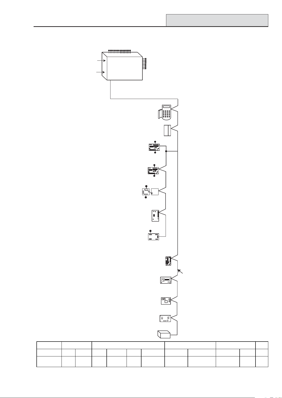
Section 2: System Architecture
16 zones on board
G3-48 Configuration
PSTN
(comm 1)
RS232
Serial Port
(comm 6)
NOTE:
RIOs, RF RIO's and
PSU's can be mixed on
the lines. The maximum
number of combined
modules is given in the
table below.
on board
telecom
area
Line
NOTE:
Valid addresses for the
*
keyprox are:
Line 1 (0, 1 & 2).
This sets the address for both
the keypad and card reader
parts of the keyprox.
*
Certain keypad and
max addresses can
be replaced by a
combined keyprox unit.
Galaxy 3-48
1
Power Unit (4) P025
or
Power RIO (4) P026
Smart PSU (4)
P015
4 outputs
8 zones
OR
RF RIO Module (4)
C076
8 outputs
on board
Cable run 1 km (max)
K
eypads (8)
*
CP027/
Keyprox (3)
CP028
Max (4)
*
MX03
4 outputs
RIO (4)
C072
8 zones
OR
4 outputs
8 zones
OR
Output Module (4) C078
NOTE: Each Output Module can simulate
up to 4 RIO's (outputs only) depending
on DIP switch setting.
Valid addresses for the Output Module are
the same as standard RIO's.
NOTE:
The Telecom, Printer Interface,
RS232, Ethernet and ISDN
modules can only be
connected to line 1.
If a Telecom module is attached,
keypad address E cannot be
connected to line 1(address E is
shown as 18 on the system).
If an RS232 module is attached,
keypad address D cannot be
connected to line 1 (address D is
shown as 17 on the system).
If an Ethernet module is attached,
keypad address B cannot be
connected to line 1 (address B is
shown as 15 on the system).
If an ISDN module is attached,
keypad address C cannot be
connected to line 1 (address C is
shown as 16 on the system).
On-board RIOs/ Smart PSUs/EN51 PSU Keypads Keyprox MAX
Galaxy Panel Zones Outputs Poss. Address Zones Outputs Poss. Address Poss. Address Poss.
3-48 (line 1) 16 8 4 2 - 5 32 16 8 0, 1 & 2, B, C, D,
4 - 16 outputs
Telecom Module (1)
E062 (comm 5)
RS232 Module (1)
E054 (comm 2)
ISDN Module (1)
E077 (comm 3)
Ethernet Module (1)
E080 (comm 4)
Printer Interface (1)
A134/A161
Twisted Pair
Screened Cable
W002
E, F
30, 1 & 24
Figure 2-1. Galaxy 3-48 System Configuration
2-1
Page 12
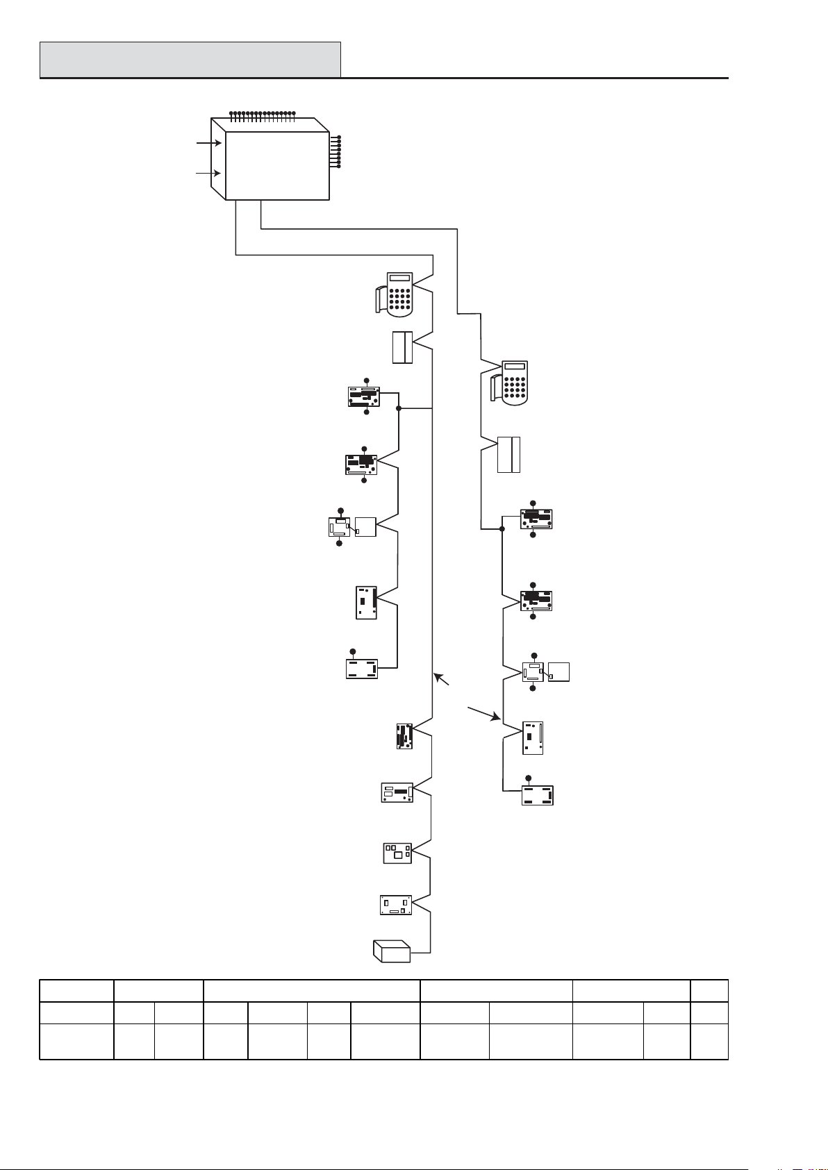
G3-144 Configuration
16 zones on board
Galaxy 3 Series Installation Manual
PSTN
(comm 1)
RS232
Serial Port
(comm 6)
NOTE:
RIOs, RF RIO's and
PSU's can be mixed on
the lines. The maximum
number of combined
modules is given in the
table below.
NOTE: Each Output Module can simulate
up to 4 RIO's (outputs only) depending
on DIP switch setting.
Valid addresses for the Output Module are
the same as standard RIO's.
NOTE:
The Telecom, Printer Interface,
RS232, Ethernet and ISDN
modules can only be
connected to line 1.
If a Telecom module is attached,
keypad address E cannot be
connected to line 1(address E is
shown as 18 on the system).
If an RS232 module is attached,
keypad address D cannot be
connected to line 1 (address D is
shown as 17 on the system).
If an Ethernet module is attached,
keypad address B cannot be
connected to line 1 (address B is
shown as 15 on the system).
If an ISDN module is attached,
keypad address C cannot be
connected to line 1 (address C is
shown as 16 on the system).
on board
telecom
Galaxy 3-144
area
Line
Line
12
NOTE:
Valid addresses for the
*
keyprox are:
Line 1 (0, 1 & 2).
Line 2 (0, 1, 2, & 3 ).
This sets the address for both
the keypad and card reader
parts of the keyprox.
*
Certain keypad and
max addresses can
be replaced by a
combined keyprox unit.
Smart PSU (8)
P015
Power Unit (8) P025
or
Power RIO (8) P026
Output Module (4) C078
8 outputs
on board
Cable run 1 km (max)
K
eypads (8)
*
CP027/
Keyprox (3)
CP028
Max (4)
*
MX03
4 outputs
RIO (8)
C072
8 zones
OR
4 outputs
8 zones
OR
4 outputs
8 zones
OR
RF RIO Module (8)
C076
4 - 16 outputs
Telecom Module (1)
E062 (comm 5)
RS232 Module (1)
E054 (comm 2)
ISDN Module (1)
E077 (comm 3)
Ethernet Module (1)
E080 (comm 4)
Printer Interface (1)
A134/A161
Twisted Pair
Screened Cable
W002
*
Max (4)
MX03
Keypads (8)
*
CP027/
Keyprox (4)
CP028
4 outputs
8 zones
4 outputs
8 zones
4 outputs
8 zones
RF RIO Module (8)
C076
4 - 16 outputs
RIO (8)
C072
OR
Smart PSU (8)
P015
OR
Power Unit (8) P025
or
Power RIO (8) P026
OR
Output Module (4)
C078
On-board RIOs/ Smart PSUs/EN51 PSU Keypads Keyprox MAX
Galaxy Panel Zones Outputs Poss. Address Zones Outputs Poss. Address Poss. Address Poss.
144 (line 1)
(line 2)
16 8 8
8
1 - 8
0 - 7
64
64
32
32
8
8
0 - 2, B, C, D, E, F
0 - 6, F
3
4
0-2
0-3
4
4
Figure 2-2. Galaxy 3-144 System Configuration
2-2
Page 13

Galaxy 3 Series Installation Manual
G3-520 Configuration
16 zones on board
NOTE:
Valid addresses for the
*
keyprox are:
Line 1 (0, 1 & 2).
Lines 2, 3 & 4 (0-6).
This sets the address for both
the keypad and card reader
parts of the keyprox.
Certain keypad and
*
max addresses can
be replaced by a
combined keyprox unit.
NOTE:
RIOs, RF RIO's and
PSU's can be mixed on
the lines. The maximum
number of combined
modules is given in the
table below.
NOTE: Each Output Module can simulate
up to 4 RIO's (outputs only) depending
on DIP switch setting.
Valid addresses for the Output Module are
the same as standard RIO's.
NOTE:
The Telecom, Printer Interface,
RS232, Ethernet and ISDN
modules can only be
connected to line 1.
If a Telecom module is attached,
keypad address E cannot be
connected to line 1(address E is
shown as 18 on the system).
If an RS232 module is attached,
keypad address D cannot be
connected to line 1 (address D is
shown as 17 on the system).
If an Ethernet module is attached,
keypad address B cannot be
connected to line 1 (address B is
shown as 15 on the system).
If an ISDN module is attached,
keypad address C cannot be
connected to line 1 (address C is
shown as 16 on the system).
Smart PSU (15)
P015
Power Unit (15) P025
or
Power RIO (15) P026
Output Module (4) C078
RF RIO Module (15)
C076
PSTN
RS232
Serial Port
Cable run 1 km (max)
K
eypads (8)
*
CP027/
Keyprox (3)
CP028
Max (8)
*
MX03
4 outputs
RIO (15)
C072
8 zones
OR
4 outputs
8 zones
OR
4 outputs
8 zones
OR
4 - 16 outputs
Telecom Module (1)
E062 (comm 5)
RS232 Module (1)
E054 (comm 2)
ISDN Module (1)
E077 (comm 3)
Ethernet Module (1)
E080 (comm 4)
Printer Interface (1)
A134/A161
on board
telecom
Galaxy 3-520
area
Line Line Line Line
1234
Lines 2, 3 and 4 have the same configuration
Cable run 1 km (max)
Max (8)
*
MX03
Twisted Pair
Screened Cable
W002
8 outputs
on board
Keypads (8)
*
CP027/
Keyprox (7)
CP028
4 outputs
8 zones
4 outputs
8 zones
4 outputs
8 zones
RF RIO Module (16)
C076
4 - 16 outputs
RIO (16)
C072
OR
Smart PSU (16)
P015
OR
Power Unit (16) P025
or
Power RIO (16) P026
OR
Output Module (4)
C078
On-board RIOs/ Smart PSUs/EN51 PSU Keypads Keyprox MAX
Galaxy Panel Zones Outputs Poss. Address Zones Outputs Poss. Address Poss. Address Poss.
520 (line 1)
(lines 2, 3, 4)
16 8 15
1 - 9, A - F
16
0 - 9, A - F
120
384
60
64
8
8
0 - 2, B, C, D, E, F
0 - 6, F
3
7
0-2
0-6
8
8
Figure 2-3. Galaxy 3-520 System Configuration
2-3
Page 14
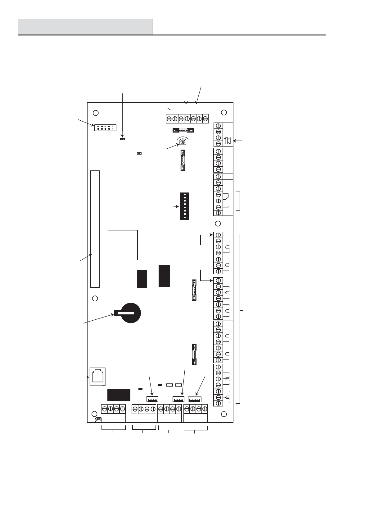
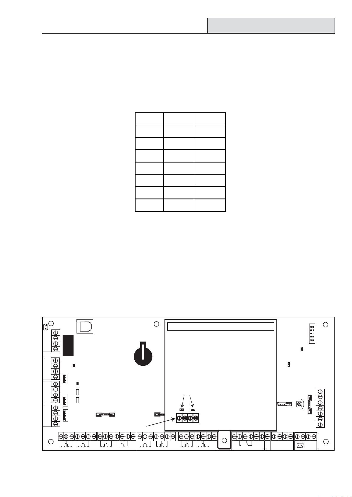
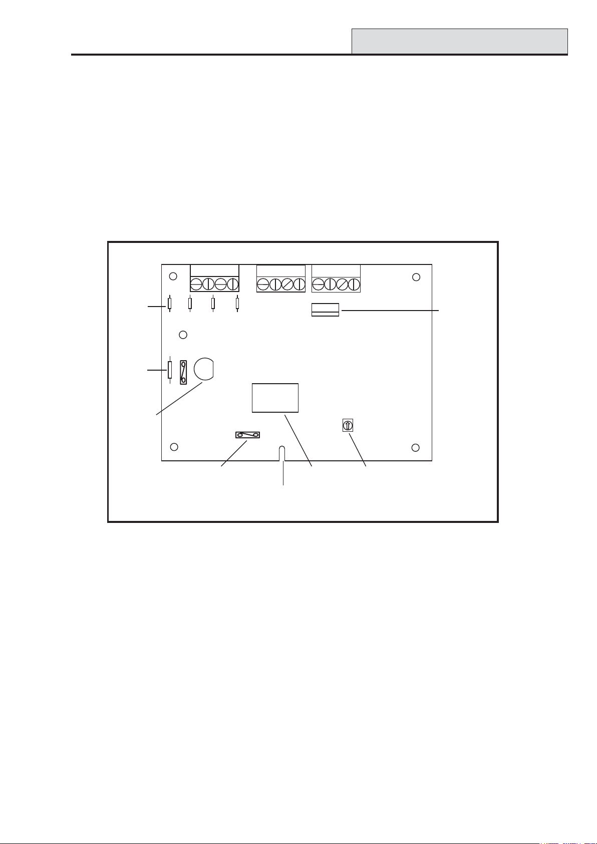
PCB Layout
ON
PCB Layout
SPI
Program
Header
Jumper Lead
for off-wall
tamper switch
TAMPER
OFF WALL
BATTERY
START UP
Galaxy 3 Series Installation Manual
Battery
TAMP
LID
-BAT
F2
SWITCH
7 8
6
4 5
2 3
1
SW3
terminals
14.5
+BAT
G
N
D
AUX
TAMP
External
loudspeaker
Relay
Output
N/C
C
N/O
4
2
RIO 1
13
+12V
4
3
RIO 0
2
1
BAT
Horn output
volume control
Pull-up switches
Leads for
lid tamper
AC
F1
BELL
RIO
ON
microswitch
Expansion card
interface
Memory
backup
battery
Telecom
Socket
LINE
ABAB
PHONE
MICRO
PROCESSOR
+12V
8
0V
7
6
+12V
+12V
8
7
6
5
+12V
0V
5
RIO 1
4
0V
3
2
0V
1
0V
0V
RIO 0
4
0V
3
2
0V
1
16 on-board zones
3-144/3-520 only
AUX2 (3-144/3-520 only)
FLASH
F3
SRAM
F4
Engineer socket
(RS485 Line 2)
LED2 (for RS232)
+12V
AUX1
RS232 Port socket
TX
CTS
RX
RTS
Engineer socket
(RS485 Line1)
LED1(for Telecoms)
GND
+12V
LK5
B2
A2
GND
LK3
A1
B1
OR
Zones 1-8 (RIO 1 line 1 (switch SW3-8 OFF))
Zones 1-8 (RIO 1 line 0 (switch SW3-8 ON))
NOTE: Zones 1-8 (RIO 0 line 1)
Fuse AUX2 controls
RS485 line 2, RIO 1 (zones 1-8)
NOTE: Fuse AUX1 controls
RS485 line 1, RIO 0 (zones 1-8)
Telecom
Connect
RS485
line 1
RS232 Port
RS485 line 2
(3-144/3-520 only)
Figure 2-4. PCB Layout
2-4
Page 15
Galaxy 3 Series Installation Manual
RS485 Expansion Module
The 7 transistorised outputs on the Galaxy 3 Series can be configured to open collectors by setting the dip
switch SW3 to the OFF position.
NOTE: Output 2 on RIO 0 (relay output) is not affected.
The following table shows which outputs are controlled by which switches.
(SW3) RIO Output
10 1
20 3
30 4
411
512
613
714
T able 2-1. SW3 T ransistorised Outputs Control
RS485 Expansion Module (G3-520 only)
The RS485 Expansion Module can be attached to the G3-520 to give 2 extra RS485 (AB) lines.
The Expansion module must be wired in a daisy-chain configuration. That is, the A line from the previous
module is connected to the A3 or A4 terminal of the Expansion Module.
The RS485 (AB) line must have a 680 ohm resistor fitted across the A and B terminals of the last module on
the line. If two lines are connected, both ends must be terminated with a 680 ohm resistor and the appropriate
link (LK1 or LK2) removed.
RS485
EXPANSION
MODULE
Jumpers
LK1
LK2
Twin
RS485
B3
A4
B4
lines
2
1
0V
+12V
4
3
0V
RIO 0
6
5
0V
+12V
8
7
0V
2
1
3
0V
A3
AUX
+12V
4
0V
RIO 1
6
5
0V
+12V
8
7
0V
1
4
3
2
RIO 0
+12V
4
2
13
RIO 1
TAMP
G
N
D
Figure 2-5. RS485 Expansion Module
2-5
Page 16
Installation Recommendations
Galaxy 3 Series Installation Manual
System Installation and Wiring
The installation and wiring must be performed by a competent engineer. For permanently connected equipment, a readily accessible disconnect device must be incorporated in the fixed wiring having contact separation
of at least 3 mm on each pole. The Galaxy 3 Series control panel must be connected to the a.c. mains supply
(230/240 Va.c. 50 Hz) via a fused connection outlet.
The fuse in the mains outlet must not exceed 3A.
WARNING: A means of isolation from the mains supply must be provided within 2 metres of
the control panel. Where live and neutral supplies can be identified, a fused spur
with a 3 amp fuse, must be fitted on the live circuit. Where live and neutral circuits
cannot be reliably identified, 3 amp fuses must be fitted to both circuits.
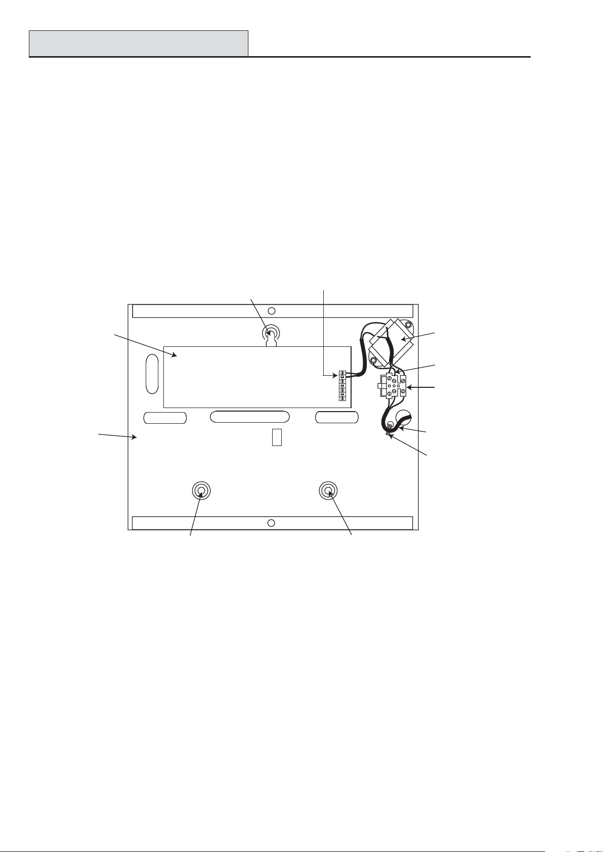
Route the mains cable through the hole on the right hand side of the enclosure base. Securely anchor the
cable to the box using the tie-wrap as shown in the following Figure:
Enclosure
base
AC connect
Attaching hole
PCB
Attaching hole
Keyhole
slot (top)
Figure 2-6. Securing the Mains Cable to the Enclosure Base
Mains
transformer
Earth wire
Terminal
block
Mains cable
Tie wrap
Secure the panel base to the wall using three 1.5" No. 8 round head steel screws through the holes provided.
The mains cable used must be a three core type (with green/yellow earth insulation) of adequate current
carrying capacity .
NOTE: The mains cable must satisfy the requirements stated in BS6500.
Connect the mains cable to the mains terminal block as follows:
• blue wire to the terminal marked N (Neutral)
• green/yellow wire to the terminal marked (Earth)
• brown wire to the terminal marked L (Live)
NOTE: No other connections to the mains connector are permitted.
All wiring must be in accordance with the latest edition of the IEE W iring Regulations, BS7671 (Requirements
for Electrical Installations).
2-6
Page 17

Galaxy 3 Series Installation Manual
System Wiring
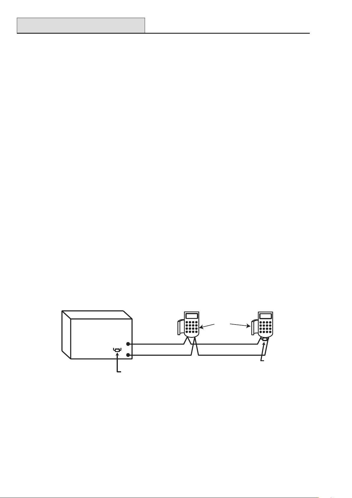
Connecting the Galaxy 3 Series to the PSTN
The T elecommunications Network V oltage (TNV) port (terminals A and B on PCB) must be permanently
connected (hard-wired) to the PSTN via a BT master socket, refer to Figure 2-7.
Note: If the BT master socket is the newer type (NTE5/CTE5), then the connection can be carried out by the
installation engineer . If the BT master socket is not an NTE5/CTE5, then the network operator must make the
connection.
Telecom
Socket
RJ45
Plug
PHONE
BT Master socket (
NTE5/CTE5
).
LINE
ABAB
BT Secondary socket (
NTE5/CTE5
).
Incoming
PSTN
Line
2
5
5
2
Figure 2-7. Connecting the Galaxy 3 Series to the PSTN
NOTES: 1. T erminals 2 and 5 on the BT Master Socket must be hard-wired to LINE A and B
terminals on the Galaxy 3 Series PCB. The connection is polarity independent.
2. It is strongly recommended that the Galaxy 3 Series panel is the only device on the line.
3. If another device is to be connected to the line, connect the PHONE terminals on the PCB
to terminals 2 and 5 on a second BT Master Socket.
There are two methods of connecting the on-board T elecom Module to the PSTN:
Method 1
Using cable suitable for connection to 2.8 mm diameter screw terminals, strip back approximately 20 mm of
the outer sheath and then remove approximately 4 mm of the insulation from the wires to be connected to the
Galaxy 3 Series PCB.
Connect terminals 2 and 5 on the BT Master socket across the LINE A and B terminals on the Galaxy 3
Series PCB, see Figure 2-7.
Method 2
Use a standard cable with RJ45 plug on one end and plug into the telecom socket on the Galaxy 3 Series
PCB. Connect the other end of the cable to the BT Master socket as described in Method 1.
2-7
Page 18

System Wiring (cont’d)
Galaxy 3 Series Installation Manual
Connecting Additional Telecom Apparatus
A BT secondary socket, allows additional telecom apparatus to be connected in series with the on-board
telecom module. Connect the PHONE terminals A and B on the PCB to the terminals on the BT secondary
socket. See Figure 2-7.
Line Monitoring
Under normal idle state conditions, the on-board T elecom Module monitors the RS485 line. The communication status is indicated by the state of the red LED (LED1) as shown in the following table:
ETATSDELNOITACIDNI
FFODELeludomotylppus.c.doN
s9.0-FFO,s10-NOnoitacinummoclamroN
llacfodnetaeslupelgniSnoita
llacmralafodnetagnihsalFnoitacinummoCdeliaF
yxalag,gnirotinommralagnirudnO
SMSdnadlog
,gnirotinommralagnirudgnirekcilF
SMSdnadlogyxalag
sehsalFgnigniReniL
langisgnignirhtiwemitni
dellaidsitigidhcaesasesluP
T able 2-2. Comms S tatus
cnummoclamroN
noitacinummoClamroN
noitacinummocrooP
nehwnoitacidnilamroN
llacgnikam
2-8
Page 19

Galaxy 3 Series Installation Manual
Stand-by Battery
St and-by Battery
The Galaxy 3 Series control panels can accommodate up to 2 x 17 Ahr batteries. Ensure that the battery
connector leads on the control panel Powers Supply Unit (PSU) are connected to the correct terminals on the
battery .
CAUTION: There is a risk of explosion if the battery is replaced by an incorrect type.
Dispose of used batteries according to the instructions.
lenaPlortnoCyrettaB
TAB-lanimretev-
TAB+lanimretev+
T able 2-3. Battery/Control Panel connections
Battery St art-up
The system can be powered up via the Battery Start-up jumper if there is no AC power . T o do this, short
out the Battery Start-up jumper for the duration of the configuration process only . Never leave the Battery
Start-up connected or else deep discharge of the Stand-by Battery will occur .
On-Board Power Supply Unit
The on-board Power Supply Unit (PSU) supplies and monitors power to the system and peripherals. The
following table shows the fuse name and value in amps.
G3-144/G3-520: The Galaxy 3 Series control panel contains four fuses. Details are given in the table below .
NOTE: The G3-48 does not require fuse AUX2.
FU S E NAME VALUE (AMPS ) MONIT OR S TYPE
AUX1 1.0 RS485 Line 1, RIO 0, Zones 1-8: +12V,
on-board comms
AUX2 1.0 RS485 Line 2, RIO 1, zones 1-8 +12V 20 mm, anti-surge
BATT 1.6 Battery 20 mm, anti-surge
BELL 1.0 Outputs RIO 0 1-4, RIO 1 1-4, Horn output 20 mm, anti-surge
T able 2-4. On-board PSU Fuses
Power Monitoring Characteristics: Low battery level: 1 1.2V
Deep discharge protection: 10.5V
Overvoltage protection: 14.7V
G3-48
The PSU total capacity is 1.5A. Internally the PSU
is split in two in order to ensure sufficient current is
always available for stand-by battery recharge.
The PSU capacity is broken down as follows:
G3-144/520
The PSU total capacity is 2.5A. Internally the PSU is
split in two in order to ensure sufficient current is always available for stand-by battery recharge.
The PSU capacity is broken down as follows:
20 mm, anti-surge
• Battery: 0.75A
• Control PCB: 0.25A
• AUX +12V : 0.5A
The PSU is available for zones/outputs and peripherals.
• Battery: 1.25A
• Control PCB: 0.25A
• AUX +12V : 1.00A
2-9
Page 20
Memory
Galaxy 3 Series Installation Manual
Memory
The Galaxy 3 Series control panel is fitted with a memory chip with its own battery backup on the main PCB.
This allows the panel to retain the system configuration, programming details and the event log for up to a year
when both the mains power and standby battery have been disconnected. The memory backup battery must
be kept in place to retain the memory during a mains failure. Re-apply power, this is known as a warm start.
T o completely erase the system memory and return to the default settings, place a piece of thin card between
the retaining clip and the memory backup battery then remove all power to the PCB for one minute. Re-apply
power and remove the card. This is known as a cold start.
The memory backup battery shoud be replaced every 5 years.
CAUTION: There is a risk of explosion if the battery is replaced by an incorrect type.
Dispose of used batteries according to the instructions.
CAUTION: Do not overstress the retaining clip when removing and installing the backup
battery. The clip must maintain a firm pressure on the backup battery at all times.
RS485 Data Communication Bus (AB Lines)
Communication between the Galaxy control panels and the modules attached to the system takes place on the
AB lines. The communication protocol is RS 485 format. The control panel constantly monitors the modules
attached to it. A break in the communication from any of the modules generates a module tamper alarm
RS485 Wiring Configurations
The system must be wired in a daisy-chain configuration. That is the A line from the previous module is
connected to the A terminal of the current module and then on to the A line of the next module.
The RS485 (AB) line must have a 680 Ω resistor fitted across the A and B terminals of the last module on the
line. If two lines are connected, both ends must be terminated with 680 Ω resistors and the appropriate link
(LK3 or LK5) removed.
Keypad/Keyprox
OR
Galaxy
Control
Panel
680 Ω
A
A
B
Fit LK3/LK5 on PCB
Module
B
AB
680 Ω EOL
Figure 2-8. Daisy Chain Configuration
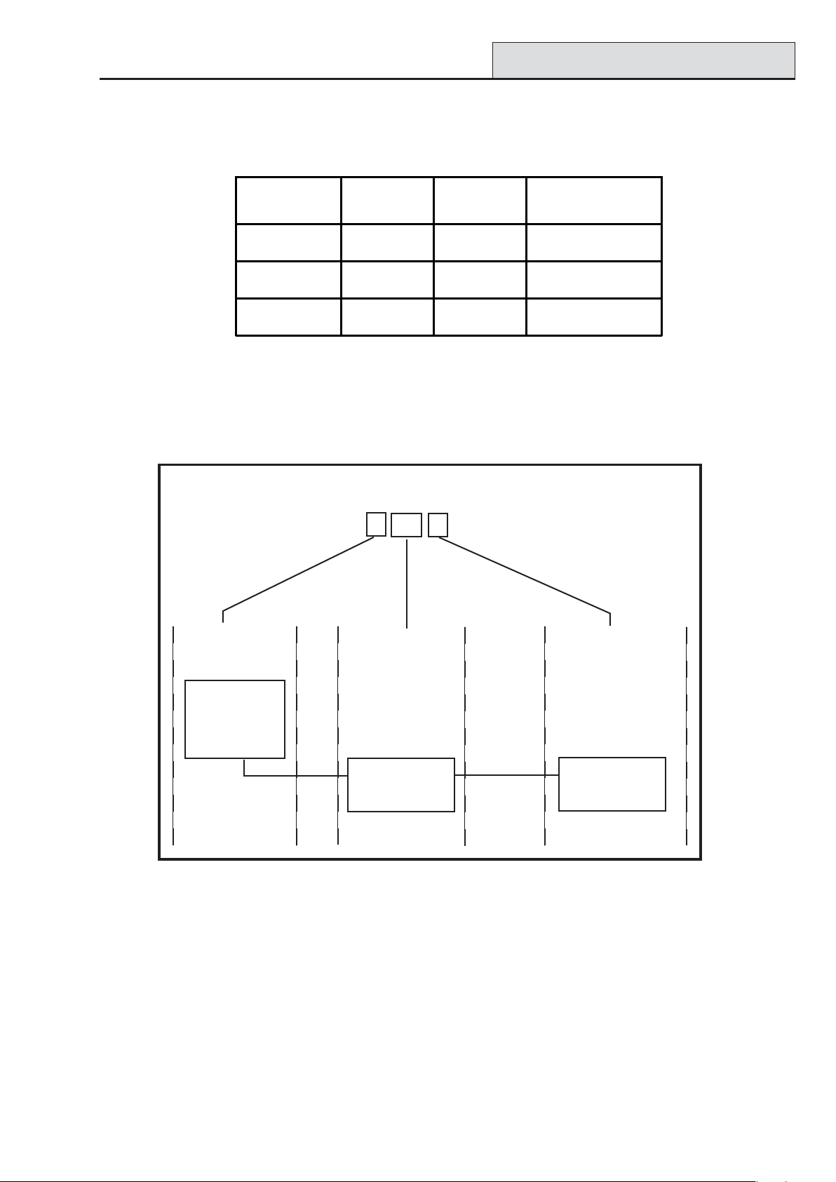
Each AB line can run in two directions from the control panel.
• Remove link LK3 (RS485 line1) or link LK5 (RS485 line2).
• Run two lines from the A and B terminals of the line.
• T erminate both Ends of Line (EOL) with a 680 ohm resistor .
NOTE: It is permissable to have different configurations on each line. For example, line 1 - Daisy chain;
line 2 - twin AB daisy chain.
2-10
Page 21

Galaxy 3 Series Installation Manual
RS485 Recommendations
Keypad/Keyprox
OR
Module
Keypad/Keyprox
OR
Module
Galaxy
Control
A
680 Ω EOL
B
Panel
A
B
Remove
LK3/LK5
B
A
680 Ω EOL
Figure 2-9. T win AB Line Daisy-Chain configuration
RS485 Wiring Recommendations
T o ensure that the system communicates at the maximum level of efficiency , the following recommendations
must be adhered to:
1. Each communication line can support 32 devices. The maximum number of devices on each line
are:
Keypads
Keyprox
RIO's/SPSU's
Output Mod ule
RF RIO
MAX
Galaxy 3-48
(Line 1 only)
8 8 per line 8 per line
3
4 8 per line
4 4 per line 4 per line
4 8 per line
4 4 per line 8 per line
Galaxy 3-144
(Lines 1-2)
3 (line 1)
4 (line 2)
Galaxy 3-520
(Lines 1-4)
3 (line 1)
7(lines 2, 3, 4)
15 (line1)
16 (lines 2, 3, 4)
15 (line 1)
16 (lines 2, 3, 4)
RS232
Telecoms
Printer
ISDN
Ethernet
1 1 (line 1 only) 1 (line 1 only)
1 1 (line 1 only) 1 (line 1 only)
1 1 (line 1 only) 1 (line 1 only)
1 1 (line 1 only) 1 (line 1 only)
1 1 (line 1 only) 1 (line 1 only)
T able 2-5. Communication Devices
2. The system must be wired in a daisy-chain configuration. Spur and star configurations must not
be used as they reduce the immunity to electrical interference.
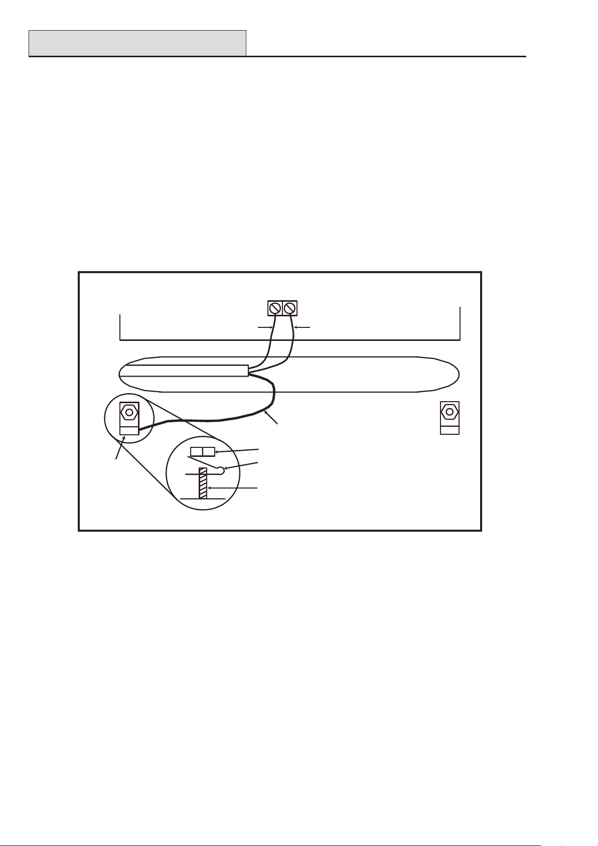
3. The cable used to connect the RS485 (AB) line must be screened twisted pair (Part No. W002) or
Belden 8723 equivalent.
4. Shielded twisted pair cable, where used, is connected to the earthing pillar on the Galaxy control
panel using the P-clip and nut supplied (refer to Figure 2-10).
5. The RS485 (AB) line must have a 680 Ω resistor fitted across the A and B terminals of the last
module on the line. If twin lines are connected, both ends must be terminated with 680 Ω resistors and
the appropriate link on the control panel PCB must be removed (refer to figure 2-9).
2-11
Page 22
RS485 Recommendations
Galaxy 3 Series Installation Manual
6. There must only be a single AB pair of wires in each of the cables.
7. The minimum voltage level is 10.5 Vd.c. with 12.5 Vd.c. being the recommended working minimum.
8. The power supply in the Galaxy control panel and remote power supplies must not be connected
in parallel.
9. The 0 V of all remote power supplies should be connected in common to the 0 V of the Galaxy
control panel.
10. Ensure that any extension loudspeakers are not wired in the same cable as an AB pair of wires.
11. Where possible, ensure that the AB cable is at least 30 centimetres away from any other cables.
12. Where possible, ensure that the AB cable does not run parallel to other cables for extended
distances (maximum 5 metres).
AB connectors
P-clip
A
data line
RS 485 cable
Nut
P-clip
Earthing pillar
(threaded)
B
data line
Cable screen
Figure 2-10. Connection of cable screen using P-Clip
2-12
Page 23
Galaxy 3 Series Installation Manual
Zone Addresses
Zones
The default setting for the zones on the Galaxy 3 Series are shown in the following table:
Galaxy
Panel
3-48 Final Exit Intruder
3-144 Final Exit Intruder
3-520 Final Exit Intruder
Zone 1001 Zone 1002
Remaining
Zones
T able 2-6. Default Zone Functions
Zone Addresses
Each zone has a four digit address; 1004, 4136. The address is made up of three reference numbers as shown
in the following figure:
Example: 3057
3
05 7
Represents Panel
Line No.
GALAXY
G3 PANEL
1 2 3 4
Represents
RIO Address
RIO
ADDRESS 05
Represents
Zone No. 1-8 on
RIO
Figure 2-1 1. Zone Addr esses
For example, zone 3057 is the detector connected to line 3, RIO 05, zone 7.
ZONE 7
2-13
Page 24
RIO Switch
Galaxy 3 Series Installation Manual
Zone Addressing with Onboard RIO Switch
The RIO switch (SW3, dipswitch 8) controls the ordering of the on-board RIO’ s. This dipswitch must be set
before powering up the panel.
NOTE: The RIO switch is not functional on the 3-48. It defaults to the Switch off configuration.
Switch off (default)
When the switch is set to this mode, the onboard RIO’s configure to the following addresses:
Onboard RIO0 Zone address range: 1001-1008 Outputs: 1001-1004
Onboard RIO1 Zone address range: 1011-1018 Outputs: 1011-1014
Switch on
When the switch is set to this mode, the onboard RIO’s configure to the following addresses:
Onboard RIO0 Zone address range: 1001-1008 Outputs: 1011-1014
Onboard RIO1 Zone address range: 0011-0018 Outputs: 0011-0014
PANEL ON-BOARD RIO RANGE TOTAL RIO's TOTAL
3-48 1001 - 1008, 1011 - 1018 16 Line 1 (4) 48
3-144 1001 - 1008, 1011 - 1018,
0011 - 0018 (switch on)
3-520 1001 - 1008, 1011 - 1018,
0011 - 0018 (switch on)
16 Line 1 (8)
Line 2 (8)
16 Line 1 (15)
Line 2 (16)
Line 3 (16)
Line 4 (16)
144
520
Table 2-7. Zone Address Ranges
Wiring Zones
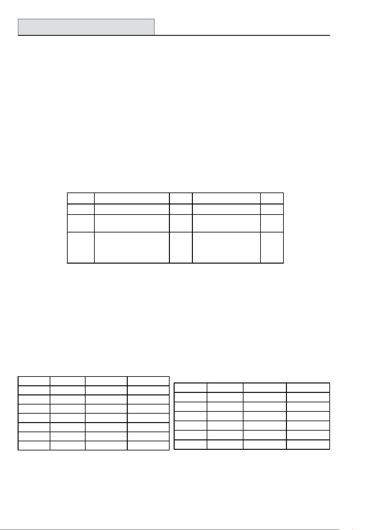
The zones on Galaxy 3 Series panels can be Double Balanced (default) or End of Line. Zones can be programmed with different resistance ranges for zone status activation (see Galaxy 3 Series Programming
Manual, IP1-0033, parameter 51.46 = Parameters.Zone Resistance). Refer to T able 2-8 (Double
Balanced) or T able 2-9 (End of Line) for details of the zone resistance and resulting conditions.
NOTE: The circuit debounce time (the period the zone must remain in a state to register a change in condi-
tion) is 300 milliseconds by default.
Preset 1 - 1k Preset 2 - 2k2 Preset 3 - 4k7
Tamper S/C 0 - 800 0 - 1800 0 - 3700
Low Res 800 - 900 1800 - 2000 3700 - 4200
Normal 900 - 1200 2000 - 2500 4200 - 5500
High Res 1200 - 1300 2500 - 2700 5500 - 6500
Open 1300 - 12000 2700 - 12000 6500 - 19000
Masked 12000 - 15000 12000 - 15000 19000 - 22000
Tamper O/C 15000 - infinity 150 00 - i nfi nity 220 0 0 - infini ty
Tamper S/C 0 - 800 0 - 1800 0 - 3700
Low Res 800 - 900 1800 - 2000 37 00 - 4200
Normal 900 - 1200 2000 - 2500 4200 - 5500
High Res 1200 - 1300 2500 - 2700 5500 - 6500
Masked 1300 - 12000 2700 - 12000 6500 - 19000
Open 12000 - infinity 12000 - infinity 19000 - infinity
Preset 1 - 1k Preset 2 - 2k2 Preset 3 - 4k7
T able 2-8. Double Balanced Zone
Resistance and Conditions
T able 2-9. End of Line Zone Resistance
and Conditions
2-14
Page 25
Galaxy 3 Series Installation Manual
Zone Wiring
Zone
Alarm
1k
1%
N/C
Tamper
N/C
500 m
Anti-mask
N/C
12k
1%
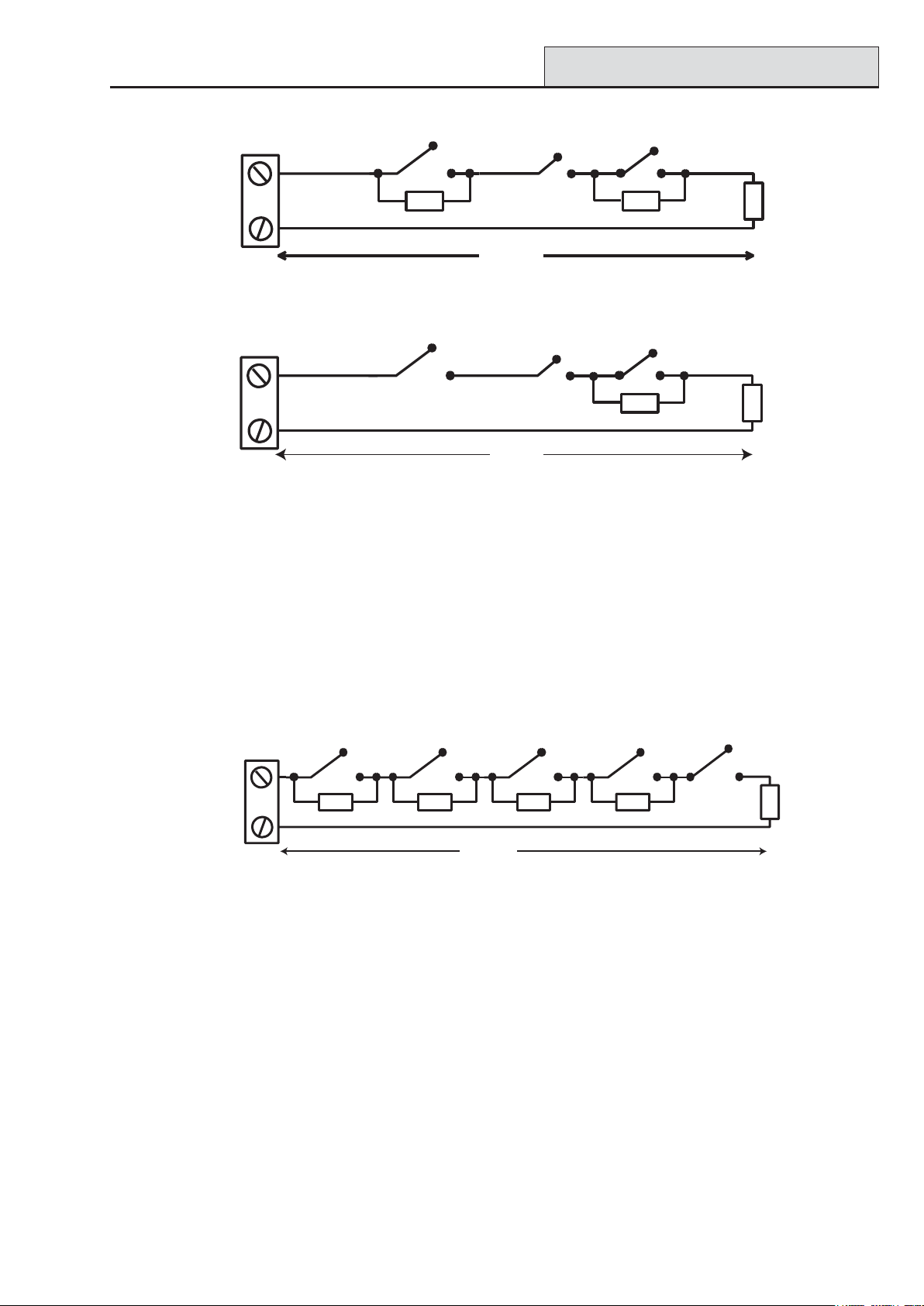
Figure 2-12. Preset 1 - Double balanced Zone/Detector wiring
Zone
Alarm
N/C
Tamper
N/C
500 m
Anti-mask
N/C
12k
1%
Figure 2-13. Preset 1 - End of Line Zone/Detector wiring
NOTE: N/C = Normally Closed
NOTE: The recommended maximum cable run from a zone to a detector is 500 metres.
1k
1k
1%
1%
Wiring Multiple Zones
Multiple detectors can be wired into a single zone as shown in the following Figure. The maximum number of
detectors that can be connected to a single zone is ten.
(10 max)
N/C TAMP
1k
1%
1k
Zone
N/C
Alarm
N/C
1k
1%
Alarm Alarm Alarm
N/C
1k
1%
500 m
N/C N/C
1k
1% 1%
Figure 2-14. Zone to Multiple Detector Wiring
Wiring Keyswitches
Latching or spring loaded keyswitches can be used to set and unset the Galaxy panels; option 52 = PROGRAM ZONES has provision to accommodate both types of transition.
If the keyswitch latches, the transition from 1 kΩ to 2 kΩ initiates the setting procedure of an unset system,
the transition from 2 kΩ to 1 kΩ instantly unsets a set system. If the system is already set, then the transition
from 1 kΩ to 2 kΩ has no effect. If the system is unset, the transition from 2 kΩ to 1 kΩ has no effect. This
is programmed as a Keyswitch in the PROGRAM ZONES option.
If the keyswitch is spring-loaded (returns to its normal position), the transition from 1 kΩ to 2 kΩ initiates the
setting procedure of an unset system and instantly unsets a set system, the transition from 2 kΩ to 1 kΩ - the
return to the normal position - has no effect. This is programmed as a Keyswitch in the PROGRAM
ZONES option.
2-15
Page 26
Terminator Zone Wiring
Galaxy 3 Series Installation Manual
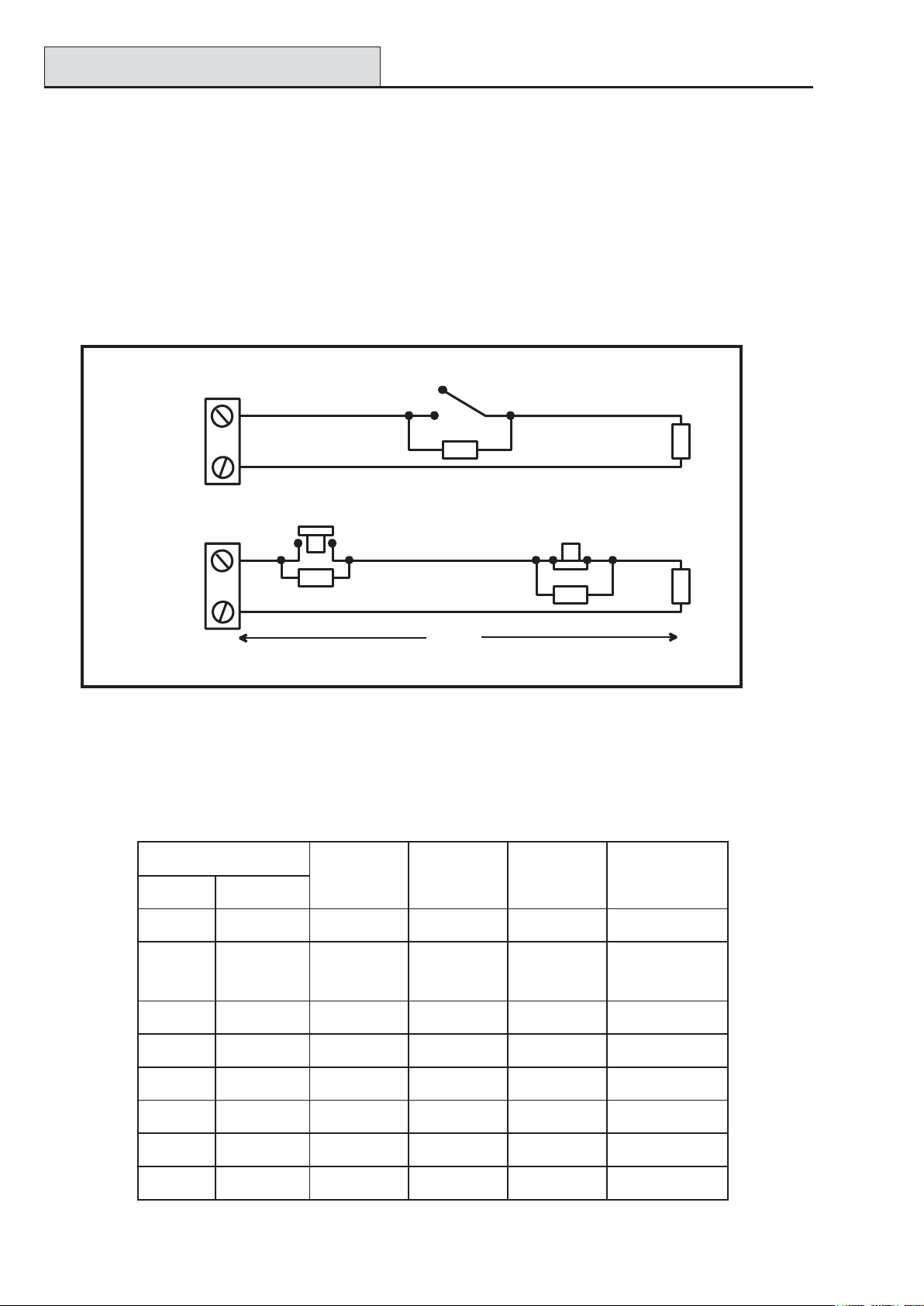
Wiring T erminator Buttons
Zones programmed as Push-Set (terminator) buttons can be open going closed (2 kΩ to 1 kΩ) or closed
going open (1 kΩ to 2 kΩ). The first activation of the terminator button initialises its status to the system.
NOTE: The first activation of a terminator may not set the system as this can be the initialisation routine. If
the system continues setting, push the button again. The system will set on the second push. This
initialisation only occurs on the first setting. All subsequent setting routines set on the first push of the
terminator.
The wiring of the terminator and keyswitch zone type is shown in the following figure:
Keyswitch
zone
Push-set
zone
Open - Closed
1k
1%
1k to unset, 2k to set
1k
1%
OR
500m
Closed - Open
1%
1k
Figure 2-15. T erminator and Keyswitch Zone Wiring
Outputs
The Galaxy 3 Series control panel on-board outputs are detailed in the following table:
sserddAtuptuO
tluafeDelbanE0eniL
tluafeD
noitcnuF
epyTgnitaR
1k
1k
1%
1%
etatSlamroN
)pu-llup3k3htiw(
10011001slleBdesirotsis
20012001ebortSeloPelgniS
30013001APdesirotsisnarTAm0
40014001teseRdesirotsisnarTAm004,V21evitisoP
11011100teSdesirotsisnarTAm004,V21evitisoP
21012100redurt
31013100mrifnoCdesirotsisnarTAm004,V21evitisoP
41014100teseRdesirotsisnarTAm004,V
nIdesirotsisnarTAm004,V21evitisoP
narTAm004,V21evitisoP
A1,V03desigrene-eD
revOegnahC
)OCPS(yaleR
04,V21evitisoP
21evitisoP
T able 2-10. Outputs
2-16
Page 27

Galaxy 3 Series Installation Manual
Output Applications
Output Applications
The outputs on the Galaxy panels, with the exception of the SPCO relay output, are transistorised outputs;
negative applied (positive removed) by default. These supply up to 400 mA and can be used to drive the
necessary output devices.
NOTE: The polarity of each output can be changed using option 53 = PROGRAM OUTPUTS
Transistorised Output
+12 V
3k3Ω
0 V
Cut 3k3Ω to give
open collector
A) LED
Output
B) Bell
Output
Output
C) Output used to trigger zone
Output
Output must be
open collector
Typical Applications
LED
1kΩ (typical)
Bell
1%
1kΩ
1%
1kΩ
Figure 2-16. Output Configuration and T ypical Applications
Note: For the appropriate 3k3Ω pull-up resistor refer to DIP switch SW3 (T able 2-1).
+12 V
+ 12 V
zone
The relay output is a single pole change over; this can be used to drive output devices that require a clean set
of contacts, isolated from the output voltage.
Horn
Normally
closed
+12 V
Single Pole
Change - 0ver
relay contacts
0 V
Normally open
Figure 2-17. Single Pole Change–Over Relay Output Configuration and T ypical application
2-17
Page 28

SPI Header
Galaxy 3 Series Installation Manual
SPI Header
The Serial Peripheral Interface (SPI) header on the Galaxy 3 Series PCB allows copying and overwriting of
programming information between panels using the SPI key .
The information is stored in a version independent format which allows panels of different versions to share
configuration information.
The panel software can also be updated using the SPI key using the menu structure, see Galaxy 3 Series
Programming Manual (IP1-0033), Option 71 = SPI Key .
2-18
Page 29

Galaxy 3 Series Installation Manual
RIOs
Section 3: Optional Modules and Facilities
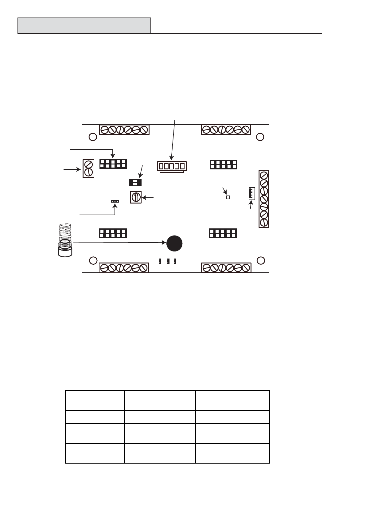
Remote Input Output (RIO) Modules – C072
Galaxy RIO’s can be added to the Galaxy 3-144 and 3-520 control panels. Each additional RIO expands the
system by eight zones and four outputs.
Outputs
1
23
4
RS 485
BA
-
Power
-
+
S
+
3k3Ω pull-up
resistors
Tamper
Switch
Addressing
SW2
R1
1
R3
LK1
R5
R7
IC2
LED
SW4
5
3
2
4
Zones
6
Figure 3-1. Galaxy RIO
LK4
IC1
78
LK3
LK2
E/E
SLAVE
SW1
IC4
Rotary
Address
Switch
IC3
Rev 0.3
The Galaxy RIO must be given a unique address before it is connected to a power supply . This
address is selected using the 16-way Rotary Address Switch (SW1). Refer to Figure 3-1.
Galaxy Panel No of RIO's (MAX) Valid Addresses
3-48 4 2, 3, 4, 5
3-144
3-520
8 (line 1)
8 (line 2)
15 (line 1)
16 (lines 2-4)
1-8 (line 1)
0-7 (line 2)
1-9, A-F (line 1)
0-9, A-F (lines 2, 3, 4)
Table 3-1. V alid RIO Addresses
3-1
Page 30

Configuring the RIO
Galaxy 3 Series Installation Manual
Connecting the RIO
The RIO can only be connected to the system while engineer mode is accessed. The RS485 (AB) line of the
Galaxy RIO must be wired in parallel (daisy-chain configuration) with the RS485 (AB) line of any keypads
connected to the system. The RIO requires 12 Vd.c. (range 10.5 to 16.0 V) and 40 mA. This can be supplied from the control panel power supply or from a remote power supply if the distance causes a large
voltage drop on the cable.
NOTE: A 3 Ampere Smart PSU (part no. P015) can be fitted in place of a RIO.
Connect the RIO terminals as follows:
+12 V (either control panel, keypad or remote power supply);
–0 V or ground (either control panel, keypad or remote power supply);
A to the A terminal of the previous module (or control panel if RIO is the first on the line);
B to the B terminal of the previous module (or control panel if RIO is the first on the line).
NOTE: If the RIO is the last module on the line, connect a 680 Ω EOL resistor across the A and B
terminals.
Configuring the RIO
The added RIO is configured into the system on exiting from engineer mode. If the message XX Mod Added
[<],[>] T o View is displayed, the system has recognised that a new module is present. Press the A or B keys
to confirm that the RIO has been added. If this message is not displayed or the RIO is not on the list of added
modules, then the RIO is not communicating with the control panel or has been set to the same address as the
RIO already connected to the system.
The flash rate of the red LED (LED1) on the RIO indicates the status of the communication with the control
panel - refer to the following Table:
etaRhsalFgninaeM
FFO9.0/NO1.0snoitacinummoclamroN
FFOylppus.c.doN
FFO5.1/NO5.1metsysotniderugifnocneebtonsah
FFO2.0/NO2.0metsyshtiwnoitacinummoctsolsahOIR
FFO1.0/NO9.0snoitacinummocroopyreV
OIR
Table 3-2. RIO LED Flash Rates
Zones
The Galaxy RIO has eight programmable zones. These default to INTRUDER. Each zone is Double
Balance monitored with a 1 kΩ resistor in series with the zone detector and a 1 kΩ (1%) resistor in parallel
across the detector switch. The change to 2 kΩ (1%) resistance registers the zone as open/alarm.
3-2
Page 31

Galaxy 3 Series Installation Manual
RIO Outputs
Outputs
The RIO has four transistorised outputs. Each output is connected to +12 V via a 3k3Ω pull-up resistor
(refer to T able 3-3). When an output is activated, the load is switched to the negative supply voltage (ground
or 0 V) of the RIO. The current available from each output is 400 mA.
The default functions and pull-up resistors of each RIO output, when connected to a Galaxy are shown in the
following T able:
.oNtuptuOnoitcnuFrotsiseRpu-lluP
1slleB1R
2ebortS3R
3AP5R
4teseR7R
T able 3-3. RIO Output Default Functions
There are several links on the RIO which, if altered when the module is powered down, modify the RIO
operation:
• LK1 - short circuit this to by-pass the RIO lid tamper switch SW2
• LK2 - cut this to configure the module as an Entry/Exit RIO
• LK4 - cut this to configure the module as a Slave or Shunt RIO (If LK2 is already cut this
modifies the exit time on the Entry/Exit RIO from 30 to 90 seconds).
For further information refer to Galaxy Remote Input Output (RIO) Installer’s Guide (Part Number:
L/051 supplied with the RIO).
Entry/Exit RIO
A RIO is configured as an Entry/Exit RIO if resistor LK2 is cut, this allows a further sub-system to be
added to the Galaxy . The Entry/Exit RIO can be armed while the main system is unset, allowing protection
of specific areas; or disarmed when the main system is set allowing access to particular areas without unsetting
a group (shunting of zones). If the main system is set and the Entry/Exit RIO is not shunted, an activation on
the RIO will cause a full alarm on the main system. The Entry/Exit RIO configuration is shown in the
following Table:
enoZnoitcnuFtluafeDnoitcnuFdemmargorPtuptuO)dexiF(noitcnuFtluafeD
1redurtnInoitcnufynA1ydaeR
2redurtnInoitcnufynA2n
roHtixE/yrtnE
3redurtnInoitcnufynA3teS
4redurtnInoitcnufynA4mralA
5redurtnInoitcnufynA
6tixEelbammargorP-noN
7laniFgoL
8hc
tiwsyeKgoL
T able 3-4. Entry/Exit RIO Configurations
3-3
Page 32

Entry/Exit RIO
Galaxy 3 Series Installation Manual
Entry/Exit RIO Zone Programming
Zones 1 – 5 operate as normal zones. If a zone is programmed as Security, any activation - whether the
Entry/Exit RIO is armed or disarmed and the Galaxy is set or unset - results in the appropriate alarm condi-
tion being generated on the control panel.
If zones 1 – 5 are programmed as Intruder, then an alarm condition can be generated on the Entry/Exit
RIO when it is armed and the Galaxy is unset.
Zones 6 and 7 behave as an Exit and Final zone respectively . The functioning of these zones is fixed and is
independent of the programming of the Galaxy . Zone 7 can be programmed as Log in order to report and
record its activation in the Galaxy event log.
The function of zone 8 is fixed as a Keyswitch. This should also be programmed as Log in order to report
and record its activation in the Galaxy event log.
Entry/Exit RIO Zone Operation
The Entry/Exit RIO is armed by the transition of zone 8 (the keyswitch zone) from 2 k Ω to 1 kΩ (reverse to
normal operation). This starts an exit/entry time of 30 seconds. Closing the contact on zone 7 (the Final
zone) or expiry of the exit time set the RIO. Any activation of zones 1 – 5 when the Entry/Exit RIO is
armed activates the Alarm output (output 4).
The Entry/Exit RIO is disarmed by the transition of the keyswitch zone (zone 8) from 1 kΩ to 2 kΩ. The
disarming procedure can be started by activating the final zone, (zone 7), and gaining access to the keyswitch
zone via the exit zone (zone 6). Activating zones 1–5 during the disarming period result in an alarm condition
being generated. If the Entry/Exit RIO is disarmed while the main Galaxy is set, then activation of any of its
zones programmed as Intruder does not generated an alarm condition on the RIO or the control panel; the
zones are shunted.
The exit/entry time can be changed from 30 seconds to 90 seconds by cutting resistor LK4.
Slave RIO
A RIO is configured as a Slave or Shunt RIO if resistor LK4 is cut, this allows a further sub-system to be
added to the Galaxy .
The programming and operation of the Slave RIO is identical to that of the Entry/Exit RIO except for zones
6 and 7, which are Intruder type zones by default. Slave RIOs do not have an Exit or Final zone, or an
exit time; they are instantly unset and reset by the transition from 1 to 2 kΩ of zone 8.
enoZtluafeD
noitcnuF
1redurtnInoitcnufynA1ydaeR
2redurtnInoitcnufy
nA2teSotliaF
demmargorP
noitcnuF
tuptuOnoitcnuFtluafeD
)dexiF(
3redurtnInoitcnufynA3teS
4redurtnInoitcnufynA4mralA
5redurtnInoitcnufynA
6redurtnInoitcnufynA
7redurtnInoitcn
8hctiwsyeKgoL
ufynA
T able 3-5. Slave RIO Configuration
3-4
Page 33
Galaxy 3 Series Installation Manual
RF RIO
RF RIO – C076
The Galaxy Radio Frequency (RF) RIO module is an optional add-on to the existing Galaxy product range.
The module acts as an RF receiver for the Ademco 868MHz transmitter range.
Features
The RF RIO contains the following features:
• Support for up to 32 RF zones (dependent upon panel type)
• Support for up to 30 RF keyfobs
• 4 transistorised outputs
Panel Keypad
Panel Keypad
Outputs
Outputs
Outputs
1
1
1
2
2
2
4
4
4
3
3
3
Panel Keypad
BA -+BA - +
BA -+BA - +
BA - + BA - +
Pull-up
Resistors
Tamper
link
Tamper
Switch
R7 R5 R3 R1
LED1
SW2
SW6
LK1
SW3
Programming
Switch
Processor
Retaining Slot
SW1
Rotary
Address
Switch
Figure 3-2. RF RIO PCB Layout
Compatibility
The RF RIO is compatible with Galaxy Control Panels 3-144 and 3-520.
Programming
Keypad
Socket
Rev 1.0
Connecting the RF RIO
The RS 485 (AB) line of the RF RIO must be wired in parallel (daisy chain configuration) with the RS 485
(AB) line of the keypad connected to it. The RF RIO requires 12 V d.c. (range 10.5 to 16.0 V) and 55 mA.
This can be supplied from the control panel power supply or from a remote power supply if the distance
causes a large voltage drop on the cable.
3-5
Page 34
RF RIO (cont’d)
Galaxy 3 Series Installation Manual
Connect the RF RIO terminals in accordance with the following Table:
lanimreTOIRFR...otdetcennoC
+)ylppusrewopetomerrodapyek,lenaplortnocta(V21+
- )ylppusrewopetomerrodapyek,l
A
B
enaplortnocta(dnuorgroV0
ehtsiOIRFRehtfilenap
iOIRFRehtfilenap
)enilehtnoeludomtsrif
)enilehtnoeludomtsrifehts
lortnocehtro(enilehtnoeludomsuoiverpehtfolanimretAehtoT
lortnocehtro(enilehtnoeludomsuoiverpehtfolanimretBehtoT
T able 3-6. RF RIO Connections
Note: If the RF RIO is the last Module on the line, connect a 680 Ω resistor across the A and B terminals.
Outputs
The RF RIO has four transistorised outputs. Each output is connected to +12 V via a 3k3Ω pull-up resistor
(refer to T able 3-6 RF RIO Connections). When an output is activated, the load is switched to the negative
supply voltage (ground or 0 V) of the RF RIO. Each output is capable of supplying 400 mA.
The default functions and pull-up resistors of each RF RIO output, when connected to a Galaxy are shown in
the following Table:
.oNtuptuOtluafeD
noitcnuF
1slleB34R
2ebortS73R
rotsiseRpu-lluP
3AP33R
4teseR32R
T able 3-7. Output Functions
NOTE: The number of pull-up resistors may vary with different hardware revisions.
RF RIO T amper
Switch SW2 on the RF RIO acts as a tamper if the T amper Link (LK1) is missing. Removing the lid from the
RF RIO enclosure activates the RF RIO tamper alarm if the system is not in Engineer Mode. The tamper
switch can be bypassed by fitting a 0 Ω link to LK1.
Addressing the RF RIO
The Galaxy RF RIO must be given unique addresses before it is connected to a power supply . This unique
address is selected using the 16-way Rotary Address Switch (SW1). The address selected will act as the
base address for the RF RIO. Subsequent addresses will be
base address + 1, base address + 2, base address + 3. For example:
Base address = 2 followed by 3, 4 and 5.
Address Ranges
This option allows the programming of the RIO addresses, which are to be simulated by the RF RIO.
For example, if the RF RIO being programmed supports 32 zones (4 RIO addresses), and the base address,
programmed at the hexi-decimal rotary switch is 02, the available addresses would be 02, 03, 04, 05. However, you may want to only respond as RIO addresses 02, 04. The remaining addresses should be disabled
and will not respond to commands from the control panel. The base address is enabled by default. All other
3-6
Page 35

Galaxy 3 Series Installation Manual
addresses are disabled by default.
Module status on the RF RIO such as lid tamper,will be reported to the panel using the address set on the
rotary switch.
RF RIO (cont’d)
RF RIO Programming
Programming of the RF RIO is achieved by connecting a Galaxy Mk7 keypad directly to the RF RIO at the
Programming Keypad Socket or the Keypad Connector Block. The Keypad is not part of the Galaxy network and must be addressed as 0.
Note: To program RF devices, please refer to RF RIO Module, Installation and Programming
Instructions, (II1-0076) supplied with the RF RIO.
Configuring the RF RIO
The RF RIO is configured into the system on exiting from engineer mode. If the message
XX Mod Added [<],[>] T o View is displayed, the system has recognised that a new module is present. Press
the A or B keys to confirm that the RF RIO has been added. If this message is not displayed or the RF RIO
is not on the list of added modules, then the RF RIO is not communicating with the control panel.
The flash rate of the red LED (LED1) on the RF RIO indicates the status of the communication with the
control panel — refer to T able 3-8.
ETARHSALFGNINAEM
FFO9.-/NO1.0snoitacinummoclamroN
FFOylppus.c.doN
FFO5.1/NO5.1metsysotniderugifnocneebtonsah
FFO1.0/NO2.0metsyshtiwnoitacinummoctsolsahOIRFR
FFO1.0/NO9.0snoitacinummocroopyreV
Table 3-8. RF RIO LED flash rates
OIRFR
3-7
Page 36
Output Module
O N
1 2
Galaxy 3 Series Installation Manual
Output Module – C078
Galaxy Output Modules can be added to the Galaxy 3 Series control panels. Each additional Output Module
expands the system up to 16 outputs by simulating the outputs of four RIO’ s
The following figure shows the main components of the Output Module.
Secondary Output
Connectors (RM1-4)
for Relay Module
Normally Open
relay output
Jumper
Tamper switch
and spring
Primary Outputs
12
+
CN3
RM3
BUZZER
ext
CN1
1
+
Primary Outputs
11
int
2
10 9
1 2
3
4
Connector for
firmware upgrade
-
DIP
Switch
O N
ISP
Rotary
Address
Switch
MODE
-
Configuration
Jumpers
TEST
TAMPER
Bypass
{
Primary Outputs
16
15
+
+
Primary Outputs
5
RM4
LED
RM2RM1
67
14 13
Engineer
Socket
(RS485 line)
8
-
CN4
B
RS485 line
}
B
A
-
+
A
- (0V)
+ (12V)
- (0V)
Module
power
supply
}
+ (12V)
S (screen cable
connect)
CN2
-
Figure 3.3. Galaxy Output Module
Addressing
The Galaxy Output Module must be given a unique address before it is connected to a power supply . This
base address is selected using the Rotary Address Switch. V alid addresses are shown in the following table.
NOTE: The zones represented by the Output Module addresses can be viewed on the panel, however they
are not used.
Gala xy Panel
No of Output Modules
(Maximum)
3-48 4 2, 3, 4, 5
3-144
3-520
8 (line 1)
8 (line 2)
15 (line 1)
16 (lines 2-4)
T able 3-9. Valid Output Module Addr esses
Valid Addresses
1-8 (line 1)
0-7 (line 2)
1-9, A-F (li ne 1)
0-9, A-F (lines 2, 3, 4)
3-8
Page 37

Galaxy 3 Series Installation Manual
Output Module (cont’d)
Connecting the Output Module
The Output Module can only be connected to the system while engineer mode is accessed. The RS485 (AB)
line of the Output Module must be wired in parallel (daisy-chain configuration) with the RS485 (AB) line of
any keypads connected to the system. The Output Module requires 12 Vd.c. (range 10.5 to 15.0 V) and
250 mA. This can be supplied from the control panel power supply or from a remote power supply if the
distance causes a large voltage drop on the cable.
Connect the Output Module terminals as follows:
+ (12 V) - either control panel, keypad or remote power supply;
– (0 V) - either control panel, keypad or remote power supply;
S (Screen cable connect) - to control panel
A to the A terminal of the previous module (or control panel if Output module is the first on the line);
B to the B terminal of the previous module (or control panel if Output Module is the first on the line).
NOTE: If the Output Module is the last module on the line, connect a 680 Ω EOL resistor across the A and
B terminals.
Configuring the Output Module
The Output Module is configured into the system on exiting from engineering mode. The procedure is identical
to that for Galaxy RIO’ s (see Configuring the RIO).
Outputs
Connecting Outputs
The Output Module has two types of outputs:
Primary outputs are taken out on contacts CN1 to CN4. The maximum current load of outputs is
400 mA. The outputs are in open collector mode.
Secondary outputs are designed for connection of up to four external Relay Modules at connectors RM1-4
(see figure 3.4). This ensures that the maximum current load will increase up to 4 A/230 V ac per output. The
Relay Module does not require an external power supply .
NOTE: When connecting external comms devices, the secondary outputs must be used. The Relay Module
has to be used in the NC mode with a pull-up link from the +12V line to one of the relay contacts.
Number of Outputs
The number of active primary outputs are determined by setting the DIP switch. Each Output Module can
simulate up to four RIO’s depending on the DIP switch setting. It is therefore possible to program one Output
Module to have 16 active primary outputs. The following table shows the DIP switch settings.
DIP Switch Settings Number of active
Switch 1 Switch 2
OFF OFF 4
ON OFF 8
OFF ON 12
ON ON 16
outputs
T able 3-10. Output Module DIP Switch Settings
3-9
Page 38
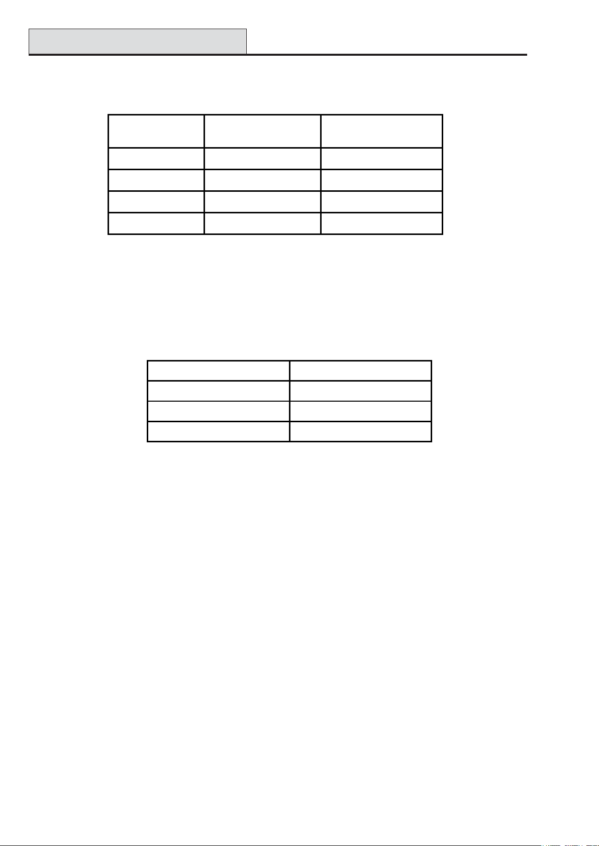
Output Module (cont’d)
Galaxy 3 Series Installation Manual
Assigning Outputs
Outputs are specified as follows: Example base address = 2.
Output Module
Address
Base = 2 CN1 1, 2, 3, 4
Base + 1 = 3 CN2 5, 6, 7, 8
Base + 2 = 4 CN3 9, 10, 11, 12
Base + 3 = 5 CN4 13, 14, 15, 16
Connector Outputs
T able 3.1 1 Output Assigning
Output Signal Change
The Output Module has one output which is used for warning about a change of state of any output. This is
controlled by the BUZZER jumper. The following table shows the possible settings.
Jumper Setting Output Function
1 - 2 (int setting) Active internal buzzer
2 - 3 (ext setting) Active relay output
Disconne cted (no jumper) OFF
T able 3-12. BUZZER Jumper Settings
Configuration Jumpers
The Output Module has three configuration jumpers, MODE, TEST and T AMPER Bypass.
MODE
By disconnecting (removing) the MODE jumper, the Output Module is switched to a mode that reflects output
types 17=Horn and 18=E/E Horn. This mode is not recommended when the Output Module is fitted with
Relay Modules as the relay contacts wear faster .
TEST
By connecting the TEST jumper all outputs become activated. Performing this test is recommended to verify
correct function of the Output Module and LED’s that are connected to outputs.
TAMPER Bypass
Connecting the T AMPER Bypass jumper deactivates the tamper function.
3-10
Page 39

Galaxy 3 Series Installation Manual
Output Module (cont’d)
Relay Module
Up to four Relay Modules can be connected to the Output Module at connectors RM1 to RM4. The Relay
Module increases the maximum current load of one output up to 4 A.
Jumpers JP1 to JP4 are used for setting up the output mode. These can either be set to NO (Normally Open)
when the jumper is on the left and middle pin, or NC (Normally Closed).
Relay Module
4
}
}
NO
NO
NO
NO
Relay4
Relay3
JP4
JP3
1
23
}
}
NO
NCNCNCNC
NO
NO
NO
Relay2
JP2
JP1
connected here
4 positions
(RM1 - RM4)
Relay1
CN3
RM3
Output Module
Figure 3.4. Location of Relay Module
T echnical Specification - Output Module
Output Module (boxed)
Dimensions: Breadth: 162 mm
Length: 150 mm
Height: 39 mm
Operating temperature: -10 deg. C to +40 deg. C
Operating voltage: 10.5V dc to 15V dc
Current consumption: Quiescent: 45mA
Maximum: 250mA (with LED’ s and relay modules)
Maximum current load: 400mA
T echnical Specification - Relay Module
Dimensions: Breadth: 50 mm
Length: 30 mm
Height: 20 mm
Power supply: Through Output Module (12V)
Operating temperature: -40 deg. C to +85 deg. C
Current consumption: 15mA
Output load: 4A/230Vac
3-11
Page 40
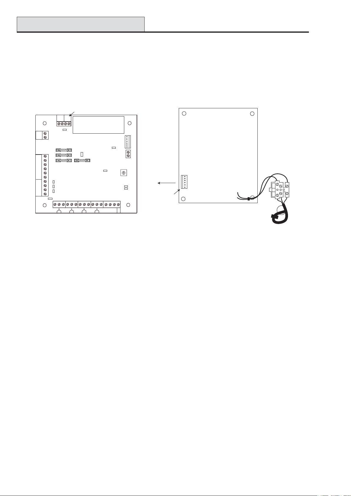
Power Supply Unit
Galaxy 3 Series Installation Manual
Power Supply Unit
The Galaxy 3 Series Power Supply Unit is available in 2 variants.
The Galaxy Power Unit is a 3 ampere power supply . The Galaxy Power RIO is a Power Unit plus an on-
board Remote Input Output (RIO) module. Each variant can be integrated with all Galaxy control panels, with
the exception of the Galaxy 8. The number of Power Units or Power RIO’ s that can be used on a system is
limited by the number of RIO’s that can be added to each panel.
Off-wall
Tamper
OW
LID
TAM P
Bell-Box
connection
Comms
Line
Outputs
+14.5
0V
+12V2
+12V1
A(DO)
B(DI)
OP3
OP2
OP1
TAM P
LK5
F1
F4
0V
F3
0V
OP4
LK4
LK3
LK2
LK1
1 1/2 2
3
HEATSINK
LK10
F2
Control Unit
5/6
3/4
5
6
4
Zones 1-8
7
13.8
From
0V
14.5
Powe r
0V
BT
LED2
AC/F
LED1
(comms)
(AC)
Rotary
Address
Switch
SLAVE
E/E
+BAT
-BAT
Block
To Control
Unit
13.8V
14.5V
Powe r
Header
BAT
AC
PWR
0V
FAULT OP
8
7/8
0V
0V
BT
AC/F
Power Block
NEUTRAL
LIVE
WARNING: The Power Block PCB
is connected to mains voltage. Always
disconnect mains supply for at least
1 minute before removing the box lid.
Mains
Terminal
Block
Figure 3-5. Power Supply Unit
Configuration
The Galaxy Power Supply Unit (PSU) consists of 2 modules, the Power Block and the Control Unit. The
PSU can be connected to the Galaxy 3 Series control panel via the RS485 (AB) line. The PSU can be used in
place of a standard RIO to overcome power problems that arise when the additional RIO is fitted distant to
the control panel.
A 6-way jumper lead connects the Power Block to the Control Unit.
The PSU has 8 zones and 4 outputs. Each PSU takes one of the 4 RIO address (2 - 5). Addressing is identical to that described for RIO Modules.
The 4 outputs are switched 0V (0V active). W ithout the jumper links (LK1-4) fitted, the outputs will float in
the OFF state. They can apply a +12V signal, if required, by fitting the appropriate pull-up jumper supplied.
LK5 will short out the off-wall tamper if it is not used.
The SLA VE and E/E links must be in place for normal operation.
F AUL T OP AC: This is an open collector transistor which is normally off. The output is activated by an AC
failure.
F AUL T OP BA T :This is an open collector transistor which is normally off. The output is activated by a
Battery Low or Battery Fail condition.
F AUL T OP POWER: This is an open collector transistor which is normally off. The output is activated by
low voltage present in +12V1, +12V2 or +14.5V.
3-12
Page 41

Galaxy 3 Series Installation Manual
Power Supply Unit (cont’d)
Installation Instructions
The installation and wiring must be performed by a competent engineer. The Galaxy 3 Series Power Supply
Unit must be connected to the a.c. mains supply (230/240 V a.c. 50Hz) via a fused connection outlet. The fuse
in the mains outlet must not exceed 3A.
The Galaxy 3 Series Power Supply Unit comes installed in the metal enclosure base. The installation procedure of the panel base is as follows:
1. Route the mains cable through the hole on the right hand side of the enclosure base. Securely anchor
the cable to the box using the tie-wrap as shown in the following Figure:
Enclosure
base
Lid Tamper
Microswitch
Control
Unit
Attaching hole
Figure 3-6. Enclosure Base
6-way jumper lead
from power block
to control unit
Keyhole
slot (top)
Powe r
Block
Off-Wall
Tamper
Micro-switch
Terminal
block
Mains cable
Tie wrap
Attaching hole
2. Secure the panel base to the wall using three 1.5" No. 8 round head steel screws through the holes
provided.
The mains cable used must be a three core type (with green/yellow earth insulation) of adequate current
carrying capacity .
NOTE: The mains cable must satisfy the requirements stated in BS6500.
3. Connect the mains cable to the mains terminal block as follows:
• blue wire to the terminal marked N (Neutral)
• green/yellow wire to the terminal marked (Earth)
• brown wire to the terminal marked L (Live)
NOTE: No other connections to the mains connector are permitted.
All wiring must be in accordance with the latest edition of the IEE W iring Regulations, BS7671 (Requirements
for Electrical Installations).
4. Power up by applying mains first. This unit can be powered up from the battery by momentarily shorting
LK10. Never leave LK10 connected, as deep discharge of the battery will occur . LK10 is for start-up
only .
3-13
Page 42

Power Supply Unit (cont’d)
Galaxy 3 Series Installation Manual
Battery
The minimum capacity battery to supply the PSU is 1x 7Ah. The maximum capacity battery to supply the
PSU is 2 x 17Ah.
Battery T est
A battery test on full load is automatically performed once an hour and during the Engineer Mode exiting
procedure. If the battery voltage falls to 10 V while the Power Supply Unit is running on the battery , then it is
automatically disconnected to prevent deep discharge of the battery .
Specifications
Electrical (based on 34 Ah battery and UK grade 3 compliance)
Input voltage: 230V a.c. (+10%/-15%) @50Hz
Output voltage (nominal): 13.8V & 14.5V
Output current (max): 3.0A
Operating temperature: -10 deg C to +40 deg C
Aux1 & Aux2
Output voltage (nominal): 13.8V
Output current (max): 0.75A each
14.5V Output (not for EN50131: grade 3 use)
Output voltage (nominal): 14.5V
Output current (max): 0.15A (when using this current, the AUX1 & AUX2 currents will
be reduced by an equivalent amount).
Battery charge current (max): 1.4A
Maximum ripple voltage: less than 100mV
Fuses
F1 (14.5V) 500mA - 20mm anti-surge
F2 (Battery) 1.6A - 20mm anti-surge
F3 ( 12V Aux1) 1.0A - 20mm anti-surge
F4 (12V Aux2) 1.0A - 20mm anti-surge
EN50131 Compliance
This product is suitable for use in systems designed to comply with EN50131-1:2004/PD6662:2004.
Security Grade - 3
Environmental Class - II
Power Supply T ype - A
3-14
Page 43

Galaxy 3 Series Installation Manual
Printer Interface
Printer Interface Module-A134/A161
The Printer Interface module allows the Galaxy to be connected to a serial printer and the contents of the
event log and the programming details of the system to be printed out. The module is available with either a:
• 25 way sub D type RS232 serial connector (part number A161)
OR
• 6 pin DIN plug (part number A134)
The printer must have a serial interface port. The printer protocol must be set to:
Protocol Setting
Star t Bit ON
Stop Bit ON
Word Length 8 Data Bits
Parity None
Baud Rate 1200
T able 3-13. Printer Protocol Settings
3-15
Page 44

Telecom Module
Galaxy 3 Series Installation Manual
Telecom Module – E062
The Galaxy T elecom module is an optional add-on to the existing Galaxy product range. It is a highly intelligent
and compact module, combining both digital communication capabilities and remote servicing facilities.
The T elecom Module is connected to the RS485 communication line 1 (AB line) on the Galaxy control panels.
This can be connected in addition to the on-board T elecom module.
As a digital communicator (digicom), the T elecom Module transmits alarm signals using the selected format;
the factory default setting is DTMF (Dual T one Multiple Frequency). As a remote servicer the T elecom
Module can be used, in conjunction with remote servicing software, to remotely access the Galaxy control
panel, allowing copying and overwriting of the program and on-line servicing.
RS485 Line
-
AB
+12V
To BT
Master
Socket
C
PHONE
D
BC A
LINE
B
JP7
JP8
Relay
Line
Transformer
R14
Engineer
Socket
680Ω EOL
LED
Telecom
connector
LINE
RJ11
Micro
Processor
Programming
Por t
TAMPER
Rev 1.0
Figure 3-7. Telecom PCB Layout
Connection to the PSTN
The T elecommunicationsNetwork Voltage (TNV) port (Line A and B, JP8) on the Module must be permanently connected (hardwired) to the Public Switched T elephone Network (PSTN) via a BT Master Socket.
Note: If the BT Master Socket is the newer type (NTE5), then the connection can be carried out by an
installation engineer. If the BT Master Socket is not an NTE5, then the connection must be made by
a network operator.
Programming the T elecom Module
The T elecom Module is programmed from the Galaxy control panel using menu option
56 - Communucations.
For further information regarding the Galaxy T elecom Module refer to TELECOM MODULE - INST ALLA TION AND OPERA TION INSTRUCTIONS (II1-0079).
3-16
Page 45

Galaxy 3 Series Installation Manual
RS232 Interface Module
RS232 Interface Module - E054
The Galaxy RS232 module provides full duplex serial communication between Galaxy control panels and PCs
or printers.
For further information regarding the Galaxy RS232 Interface Module refer to RS232 Module, Operating
Instructions (IO1-0054)
SW2
PROM1
TAMPER
LK1
S1
BA - +
B
LINE
A
12V
+
SW1
S
JP1
LD1
DIP
ON
MEM BK
8
7
6
5
4
3
2
1
Figure 3-8. RS232 Interface Module
LD3
COPY
JP2
SW3
COPY
SW4
LD4
LD2
25 Way
RS232
Interface
OVERWRITE
Rev 1.11
NOTE: The position of components on the RS232 PCB may vary with different hardware revisions.
NOTE: This module cannot be used to copy or overwrite programming from the Galaxy 3-144 or 3-520
panels.
Interface with a PC
The panel can be directly linked to a PC via the RS232 module allowing remote servicing via Galaxy Gold or
system supervision via Alarm Monitoring or SIA protocol.
3-17
Page 46

Printer Interface
Galaxy 3 Series Installation Manual
Serial Printer Interface
The module can also operate as an interface to a serial printer. Refer to the following T ables for printer
protocol settings.
DIP Switch Function Setting
1 Pr inter/P C interfa c e ON – Printer
2 Stop Bits OFF – 1
3 Word Length OFF – 8
4 Even/Odd Parity N/A
5 Parity ON/OFF OFF – No Parity
6 B AUD Ra te Must match pri nter Baud Ra te
7
8
T able 3-14. RS232 Module Printer Interface Protocol
Ba ud Ra te D IP Switch Setting
678
300 Off Off Off
600 Off Off On
1200 Off On Off
2400 Off On On
4800 On Off Off
9600 On Off On
19200 On On On
38400 On On On
T able 3-15. Baud rate DIP Switch Settings
3-18
Page 47

Galaxy 3 Series Installation Manual
ISDN Module
ISDN Module – E077
The ISDN Module is an optional add-on to the existing Galaxy product range. It connects directly to the
Galaxy RS485 communication bus, allowing signalling and remote servicing over an ISDN network. The
ISDN Module is housed inside the Galaxy enclosure in the same way as the existing T elecom Module.
The ISDN Module supports the following features:
• Full existing Galaxy T elecom Module functionality
• Analogue/digital/X.25 communication
• Support for existing DTMF , SIA, Contact ID and Microtech signalling formats in addition to two
receiver specific X.25 protocols
• Hardware and software line snatch
• Comprehensive line fail detection and rteporting
• T wo-way communication using B-Channel and D-Channel.
The ISDN Module is allocated keypad address C on line 1 of the panel, and reports itself as Comm Mod 3.
As a result of the addition of the ISDN Module, keypad address C is not available on line 1. If this keypad is
required, the ISDN Module should be removed.
ISDN IN ISDN OUT
Jumper
Links
JP2 JP1
PROCESSOR
PROM
JP3
D22
LED's
D23
12V GND RS485
IMOD 1 Rev 4
Figure 3-9. ISDN PCB Layout
The position of components on the ISDN PCB may vary with different hardware revisions.
Programming the ISDN Module
The ISDN module is programmed from the Galaxy 3 Series control panel using menu option
56 - Communications. The menu is allocated as option 3 after the Int. T elecom and Ext. RS232 Modules.
3-19
Page 48

Ethernet Module
Galaxy 3 Series Installation Manual
Ethernet Module - E080
The Ethernet Module is an optional add-on to the Galaxy 3-144 and 3-520 panels. It is a highly intelligent and
compact module, combining alarm signalling, remote servicing and integrated facilities over Ethernet LAN and/
or WAN. The Ethernet Module connects to 10 Base T Ethernet networks both supporting UDP/IP and TCP/
IP protocols.
The Ethernet module supports the following features:
• Full alarm signalling on SIA
• Microtech protocol signalling with Alarm Monitoring Software V3.1/3.2
• Remote servicing via remote servicing software
LED3
Programming
Header
Processor
Engineer
Socket
+
S
-
AB
Line
LED1
SKT1
Processor
LED2
SKT2
Rev. 1.0
Figure 3-10. Ethernet PCB Layout
NOTE: The position of components on the Ethernet PCB may vary with different hardware revisions
Configuring the Ethernet Module
The added Ethernet Module is configured into the system on exiting from engineer mode and is allocated
keypad address 15 (B). If the message XX Mod Added [<],[>] T o V iew is displayed, the system has
recognised that a new module is present. Press the A or B keys to confirm that com 4 has been added. If
this message is not displayed or the Ethernet Module is not on the list of added modules, then the Ethernet
Module is not communicating with the control panel.
The flash rate of the red LED (LED3) on the Ethernet Module indicates the status of the communication with
the control.
Ethernet Communication
The green LED (LED1) is illuminated when the Ethernet Module is connected to Ethernet.
The amber LED (LED2) flashes when the Ethernet Module is sending or receiving data.
For further information regarding the Ethernet Module, refer to Ethernet Module, Installation Instructions
(II1-0080).
3-20
Page 49

Galaxy 3 Series Installation Manual
Optional Software Packages
Remote Servicing Suite
The Remote Servicing Suite contains two main applications:
• Event Monitoring Software.
• Galaxy Gold Remote Servicing Software.
Event Monitoring
Alarm Monitoring is an advanced, high performance software program that allows a PC to receive and store
detailed event and alarm information from Galaxy control panels.
Galaxy Gold
Galaxy Gold is an advanced, high performance software program that allows a PC to communicate and
control the Galaxy control panels. The software program can also upload, store and download the control
panel programming.
NOTE: This software program is only available to registered Galaxy Gold users.
User Management Suite
User Management Suite is a software program designed specifically for in-house security managers, and
allows access to key features of the Remote Servicing program in order to facilitate:
• Event log copying
• Holiday period changes
• Summer time date change
• User code amendment
METSYSEDOCREDRO
tiKgnicneciLetiuSgnicivreSetomeRTIK030R
edargpUetiuSgnicivreSetomeRDC-030R
iLetiuSgnicivreSetomeRTIK-10-130R
UTIK-10-230R
tiKecneciLetiuStnemeganaMres
edargpUetiuStnemeganaMresUDC-230R
)elgnoD(tiKecnec
)elgnoD(edargpUetiuSgnicivreSetomeRDC-130R
)elgnoD(tiKecneciLetiuStnemeganaMresUTIK-10-330R
rgpUetiuStnemeganaMresUDC-330R
)elgnoD(eda
T able 3-16. Galaxy PC Products and Order Codes
3-21
Page 50

Galaxy 3 Series Installation Manual
3-22
Page 51
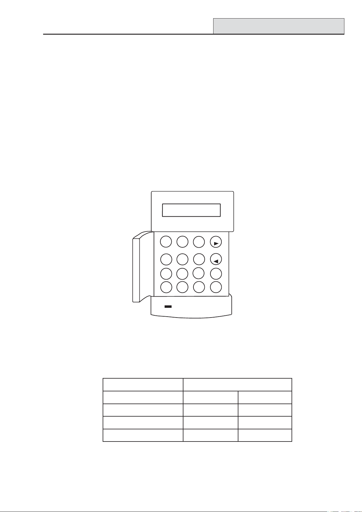
Galaxy 3 Series Installation Manual
Mk7 Keypad/KeyProx
Section 4: The Galaxy Mk7 Keypad/KeyProx
NOTE: References in the text to the Mk7 keypad also includes the KeyProx in this section.
General
The Galaxy Mk7 keypad/keyProx has the following features:
• a 2 x 16 alphanumeric character backlit display
• 16 backlit push buttons as shown in figure 4-1
• internal horn
• power indicator LED
• Lid tamper
• Off-wall tamper
• Address switch
• RS485 serial connector
GALAXY 144 V5.00
08:58 TUE 22 NOV
1
2
4
5
8
7
0
A
3
B
6
ent
9
esc
#
*
Figure 4-1. Galaxy Mk7 Keypad/KeyProx
Power Consumption
The Galaxy Mk 7 keypad/keyProx requires a 12 Vd.c. supply – from the control panel or a remote power
supply . The current consumption of the keypad/keyProx is:
edoMdapyeK7kMxorpyeK7kM
)FFOthgilkcab(lanimoNAm53Am57
NOthgilkcaBAm55Am59
tnerruCmralAmumixaMAm09Am03
T able 4-1. Keypad/KeyProx Current draw
4-1
warDtnerruC
1
Page 52
Keypad Installation
Galaxy 3 Series Installation Manual
Wiring the Keypad/KeyProx
A 16-way rotary address switch is used to address Galaxy LCD keypads. The address switch assigns a
hexadecimal address value to the keypad.
NOTE: Any change to the keypad address must be made when the power is disconnected from the
keypad.
Addressing
The valid addresses of the keypad on each of the Galaxy panels are shown on the following Table:
Control Panel Addresses Line Valid Keypad Valid Keyprox
Galaxy 3-48 1 0 - 2, B, C, D, E, F 0, 1, 2
Galaxy 3-144 1
Galaxy 3-520
2, 3, 4
0 - 2, B, C, D, E, F
2
0 - 6, F
1
0 - 2, B, C, D, E, F
0 - 6, F
0, 1, 2
0, 1, 2, 3
0, 1, 2
0, 1, 2, 3, 4, 5, 6
T able 4-2. Valid Keypad/KeyProx Addresses
It is possible to add additional keypads at any unused comms module addresses (B, C, D and E) as detailed
in the following NOTE. These must be standard keypads. An engineer keypad can also be used at address F .
NOTE: On Line 1, keypad addresses B, C, D and E are not available if the Ethernet,
ISDN, RS232 or T elecom modules respectively are fitted.
Keypad/KeyProx Installation Procedure
1. T o attach the keypad to the wall, the back plate must first be removed from the front plate. T o do this,
insert a suitable tool into both openings at the bottom of the keypad and turn the tool gently .
CAUTION: When the keypad is separated make sure that the anti-static precautions are taken
with the keypad pcb to avoid damage from esd (electro static discharge).
Connections to the terminals are:
rotcennoC
slanimreT
A lenapotenilA
B lenapotenilB
+ tupni.c.dV21
– V0
sdapyeKyxalaG
T able 4-3. Keypad/keyProx T erminal Connections
2. Use the backplate as a template, then mark the locations for the three attachment screws in the
required position.
3. If it is a new installation, use the keyhole slot at the top of the backplate and the two elongated
holes at the bottom. If replacing an existing Mk3 keypad with a Mk7 keypad, use the keyhole
slot at the top of the backplate and the two knockout holes at the bottom. This means that you
can use the existing holes in the wall, whist keeping the backplate in the same position.
4-2
Page 53

Galaxy 3 Series Installation Manual
Keypad Installation (cont’d)
4. If you are using a wall-run cable for the keypad (A, B, +12V, 0V) position the cable behind the
back plate in the cable channels provided. The cable can be run in from either the top or the
bottom of the back plate. Use a sharp tool to remove the plastic from the top or the bottom of the
cable guides on the back plate skirting.
CAUTION: Use of any screws other than No. 6 Pan-head can damage the keypad
mouldings.
5. Make sure that the keypad wiring is fed through the large opening on the keypad backplate, then
position the keypad base on the wall and attach it securely with the three No. 6 Pan-head screws.
6. If an off the wall tamper is required, using a No. 6 Pan-head screw , secure the sacrificial wall
tamper, indicated in Figure 4-2, to the wall. Make sure that the tamper knockout is still
connected to the backplate moulding.
7. Connect the A, B and power wires to the correct terminals of the removable, four-way connector
block.
cable
channel
cable
stowage
area
elongated
hole
aperture
keyhole slot
+
B
A
4-way
connector
aperture
sacrificial
wall
tamper
knockout
-
hole
Figure 4-2. Galaxy Mk7 Keypad/KeyProx Backplate Installation
8. Make sure that the power is disconnected then set the keypad to the required address using the 16
way rotary switch on the PCB.
9. To re-assemble the keypad, connect the four-way connector block onto the pins on the keypad
PCB. Attach the keypad front plate to the back plate by inserting the two clips on the top of the
keypad front plate into the two apertures at the top of the keypad back plate, then gently push the
bottom of the keypad front plate into the back plate until it snaps securely into place. Ensure the front
and back sections of the keypad are securely fixed at all points of the keypad perimeter.
Note: The keypad door can be re-orientated to allow opening from either the left or right-hand
sides. However, fitting or removal of the door must only be done when the front plate is
detached from the back plate. Attempting to remove or install the door , when the keypad is
assembled, may cause damage to the keypad mouldings.
4-3
Page 54

Adding/Removing Keypads
Galaxy 3 Series Installation Manual
V olume Control
Where fitted, the Mk7 keypad/keyprox has a volume control switch marked VOL at the bottom right-hand
corner of the pcb. Make sure the keypad/keyprox is powered up and adjust to the desired volume (+ or -)
for buzzer functions. Refer to Appendix F for keypad/keyprox part numbers with volume control function.
Adding a Keypad/KeyProx to the System
When adding a keypad to an existing system, the following points must be considered:
1. Ensure that the keypad to be added has a unique address from the other keypads on the system.
2. Ensure that the keypad has a valid address.
3. Connect the keypad to the system - refer to the Keypad Installation Procedure.
Note: A new keypad can only be configured into an existing Galaxy system from engineer mode.
4. Access engineer mode.
5. Connect the RS485 (AB) line of the keypad in parallel with the RS485 (AB) line of the
existing keypads.
6. Connect + and – terminals of the keypad to a power supply.
7. Exit engineer mode - engineer code + esc:
8. The Mk7 keypad displays the message 1 MOD. ADDED — esc=CONTINUE. Press the esc
key; the keypad returns to the unset banner.
NOTE: If this message is not displayed, the keypad is not communicating with the control panel and has not
been configured into the system. In this case all connections and addresses should be rechecked.
NOTE: If adding a keyProx to the system, the message 2 MOD ADDED will be displayed to indicate that
both a keypad and MAX have been added to the system.
9. The keypad is now configured into the system.
Removing a Keypad/KeyProx from the System
A keypad can only be removed from an existing Galaxy system from engineer mode
1. Access engineer mode.
2. Disconnect the keypad.
3. Exit engineer mode. The message 1 MOD. MISSING — [<],[>] to V iew is displayed
4. Press the A or B key. The message KEYP AD XX —
5. Press the
returns to the unset banner.
NOTE: If removing a keyProx from the system the message 2 MOD MISSING is displayed to indicate
both a keypad and MAX have been removed from the system. Each should be removed separately
by pressing the * key twice.
key to acknowledge and accept that the keypad has been removed. The keypad
4-4
=REMOVE MODULE is displayed.
Page 55

Galaxy 3 Series Installation Manual
Keypad Operation
Self Diagnostics
The keypad has a self diagnostic feature that is used to test the operational status of the inputs and outputs of
the keypad.
The test is started by disconnecting the power from the keypad, then reapplying the power while pressing the
ent key. The test routine commences immediately. Each test last approximately four seconds. The test is
terminated by removing the power.
• Keypad address is displayed
• Keypad buzzer is activated and a bell symbol is displayed.
• Power LED is illuminated and an a.c. ( ) and LED ( ) symbol is displayed.
• Keypad keys are displayed. Each key press is confirmed by the buzzer sounding and the key display
being highlighted.
• To return keypad to operational mode remove and reapply power .
Keypad/KeyProx Operation
Number Keys
The number keys are used to enter the Personal Identification Number
(PIN) which identifies users to the Galaxy and permits access to the system
options. The PIN Code is a 5 or 6 digit number .
edoCtluafeD
reenignE332211
resUetomeR012345
reganaMretsaM54321
noitasirohtuA12345
Table 4-4. Default Codes
5
8
2
3
6
9
1
4
7
0
The number keys are also used, once access to the system has been gained, to select and modify options.
View Keys
These keys are used to initiate the setting of the Galaxy
A
B
Pressing the A or B key immediately after a valid PIN has been entered starts
one of the routines for setting the system. The A key initiates the full setting of
the Galaxy . The B key starts the part setting routine.
Once the system has been successfully accessed the A key can be used to
step forward through the Galaxy menu options and the B key to step backwards.
The A and B keys can also be re-programmed for different functions.
Enter Key
ent
The ent key is used to:
• Access the menu options
• Confirm the programming selections
4-5
Page 56

Keypad Operation (cont’d)
Escape Key
The esc key cancels any modification made to the current option and returns
esc
to the previous option level. Successive pressing of this key returns the user
to the banner display .
The esc key also aborts the setting routine if pressed during the exit time.
Hash Key
The # key is used :
• as a toggle key , which enables or disables the programming features of
the Galaxy options, for example, enabling the OMIT attribute of a zone,
#
• to give additional information on the programming options, for example
pressing the # key while in option 22=DISPLA Y LOG shows details of the
user number, descriptor and keypad used to cancel alarms or unset the
system.
• to activate the Duress and PA outputs; enter a valid user code followed by two
presses of the # key , then the ent key to activate the duress alarm.
Galaxy 3 Series Installation Manual
Star Key
*
The º key is used:
• to correct or erase PINs in the CODES option and alpha-numeric
descriptors in the TEXT option,
• to start printing from the current event when viewing option
22=DISPLA Y LOG.
• to display the set status of the groups. When Show Status (refer to option
58.6=KEYP ADS.Show Status) is enabled, pressing the º and # keys simultaneously
when the normal banner is displayed indicates the group set status.
R = Ready to Set (all active zones in group closed)
F= Faulted (at least one of the active zones in the group is open)
S = Set
P = Part Set
L = Locked Out
- = Group not assigned to keypad
Note: The Show Status indicates the set conditions of groups when the system is set
(keypad blank) or unset (normal banner). Show Status does not operate while
engineer mode is accessed.
Pressing the º and # keys again toggles the display to show the status of the groups
individually . T o move between each groups, press the º and A or the º and B keys
simultaneously .
Pressing the º and # again returns the keypad to the banner display .
4-6
Page 57

Galaxy 3 Series Installation Manual
Keypad Operation (cont’d)
Galaxy 3-520
The Galaxy 3-520 has more than eight groups; these are displayed on the keypad in blocks of eight groups.
Press the A or B key to display each of the group blocks.
Power LED
The green power LED indicates the status of the a.c. power supply and the stand-by battery .
DELrewoPsutatS.c.asutatSyrettaBsutatSesuF
NOKO.c.aKOyrettaBKOsesuF
hsalfwolSliaF.c.aKOyrettaBKOsesuF
hsalFkciuQKO/
liaF.c.awoLyrettaBnwolbesuF
T able 4-5. a.c./Battery S tatus Indicator
NOTE: It is advised that a suitably rated stand-by battery is fitted to the system in order to provide
continued protection in the event of a mains failure. The battery is not included.
Display
The Galaxy Keypad/KeyProx have a 2 x 16 character backlit display used to display programming information and system status.
GALAXY 520 V5.00GALAXY 520 V5.00
GALAXY 520 V5.00
GALAXY 520 V5.00GALAXY 520 V5.00
08:58 TUE 22 NOV08:58 TUE 22 NOV
08:58 TUE 22 NOV
08:58 TUE 22 NOV08:58 TUE 22 NOV
4-7
Page 58

Keyprox
Galaxy 3 Series Installation Manual
The Galaxy KeyProx
General
The KeyProx is a standard Mk7 keypad with a proximity card reader built in to the lower right corner. This
allows users to set and unset the system, using proximity cards, rather than a pin.
NOTE: The keyProx is not intended for use as a door control unit. Installation and wiring of the KeyProx is
identical to the Mk7 keypad.
Addressing
Both the KeyProx and reader share a common address, set by the rotary address switch.
An address must be chosen which will be valid for both the keypad and MAX.
Please note that in order for the reader to operate, MAX mode must be enabled in the panel programming,
(option 63.2.1 = Options.MAX.MAX Mode). The MAX addressing function in option 63.2.2 = MAX
Address, is not required for keyprox units.
Operation
The operation of the KeyProx is identical to the Mk7 keypad. The proximity reader is seen by the panel as an
on-line MAX reader. It is programmed in exactly the same way with the exception that it does not require to
be addressed (this being set already by the rotary switch).
Card T ypes
The KeyProx can read standard ASK (Amplitude Shift Keying) type cards up to 34 bit. A self learn feature is
incorporared into the KeyProx to aid in card programming.
For further details on how to set up user cards, to set and unset the system, refer to Galaxy 3 Series Pro-
gramming Manual (IP1-0033), Option 42 - Codes.
4-8
Page 59

Galaxy 3 Series Installation Manual
MAX
3
Section 5: Door Control Module - MAX
3
Introduction
The MAX3 is a proximity reader access control device for a single door, which can also be used for setting
and unsetting of your alarm control panel. The MAX3 can be configured in one of two ways:
Standalone
In this configuration the MAX3 can be used for either door control or alarm system set/unset control, by either
connecting the internal relay output to a door lock, external relay or into the keyswitch zone of the alarm
system. When in standalone mode the MAX3 is programmed and operated using the MAX3 proximity cards
or tags.The proximity cards and tags each have unique ID numbers and must be identified to the MAX
before being used to operate the system. The MAX3 memory can store up to 999 ID numbers, including at
least three reserved for Masters. Once programmed, the ID number of the tags and cards are stored indefinitely in the MAX3 memory until voided (removed) or erased. Removing power from the MAX3 does not
erase the programming memory .
Note : The MAX3 defaults to standalone mode. It can be configured to on-line mode directly from and of the
Galaxy 3 Series control panels.
On-line
3
The MAX3 can operate in on-line mode, with the Galaxy 3 Series control panel range, as a completely integrated module on the system. In this configuration the MAX3 can be used for both door control and alarm
system set/unset control with complete user traceability stored within the Galaxy control panel.
For detailed instructions on how to programme the MAX3 onto the system in on-line mode refer to Galaxy 3
Series Programming Manual IP1-0033, Option 63.2=MAX.
Installing the MAX
MAX3 Pack
Y our Max3 pack contains the following:
• Max3 proximity reader *
• Max3 drilling template
• Max3 installation instructions
• Surge suppressor
* The MAX3 is supplied with 3 metres of 12
wire E11 1235 AWG cable which is fixed and
sealed through a keyhole opening on the rear
surface of the MAX3 .
3
Mounting the MAX
T o mount the MAX3 use the step by step
diagrams provided with the drilling template.
The drilling template should be used as an aid
to locate the holes required to secure the
MAX3 and insert the connection cable.
The MAX3 comes with an infra red lid tamper.
The tamper is activated when the lid is removed from the MAX3 unit.
3
5-1
Page 60

Installation (cont’d)
Galaxy 3 Series Installation Manual
Wiring the MAX
3
The MAX3 unit can be connected to the control panel in one of two ways depending upon whether it is being
used in an on-line or standalone configuration. The diagrams below provides details for both configurations.
The MAX3 relay is configured in either the NC or NO configuration depending upon the variant purchased
(MX03 - Normally Closed, MX03-NO - Normally Open).
NOTE: Fitting of an external relay may be required when using AC powered locks.
! -!
./.
(
+
'
%&&
()*#
!
&
,
,$
()*#
#!
#!
!
"!!
!
!
! $
$
! $
%&&
$
$
$
()*#
(#
Figure 5-1. Online Connection diagram
#!
#!
#!
!
"!!
!
()*#
! $
$
! $ /+0
$
! $
%&&
$
$
$
! 3!
454
(
2
(#
'
%&&
()*#
+
+$
)- $.
)- $.
()*#
-&
1
+ &
&
,%
!
5-2
Figure 5-2. Standalone Connection diagram
Page 61

Galaxy 3 Series Installation Manual
Configuring MAX
3
Configuring a MAX3 Reader into the System
MAX3 readers can only be configured into the Galaxy system from engineer mode.
Access engineer mode.Wire the MAX3 as per the instructions given in Figures 5-1 or 5-2
The MAX3 reader must be assigned as either an On-Line or a Stand-Alone module using option 63.2.2 =
OPTIONS.MAX.MAX Address:
0 = On-Line: The MAX3 is fully integrated with the Galaxy system and communicates via the AB line,
sharing system resources and facilities.
1 = Standalone (default): The MAX operates as an entirely independent unit. The Galaxy does not
monitor the MAX3 for alarms, tampers or power failure.
Configuring as On-Line MAX
1. Connect power to the MAX3 as per Figure 5-1.
2. Ensure that the MAX mode is enabled (option 63.2.1 = OPTIONS.MAX.MAX Mode).
3. Select option 63.2.2 = OPTIONS.MAX.MAX Address and press the ent key; the Galaxy panel
may prompt (depending on model) for the AB line (1 – 4)) that is to be searched; select the line and
press the ent key . The Galaxy searches for the MAX3 with the highest address. New MAX3 readers
are addressed as 8 (standalone) by default.
4. Only if adding a new MAX3 reader: On locating the MAX3 address, the keypad prompts for the
OPERA TING MODE of MAX3 to be assigned: select 0 = On-Line and press the ent key .
NOTE: If reprogramming an existing stand-alone reader, the system automatically selects the On-
Line operating mode.
The MAX3 can then be readdressed. The keypad displays the current address of the MAX3 and the range of
valid addresses. Enter the new MAX3 address and press the ent key; the Galaxy then reprograms the address of the MAX3. The keypad indicates the old and new MAX3 addresses and the status of the reprogramming.
All new MAX3 readers default to address 7.
NOTE: It is recommended that when adding a reader, it is addressed as the lowest available number on the
line.
3
When the reprogramming is complete the MAX3 bleeps, the LEDs on the MAX3 switch off and the keypad
display returns to 2 = MAX Address.
5. Exit engineer mode - engineer code + esc: the keypad displays the message 1 MOD. ADDED esc=CONTINUE. LED 2 on the MAX3 reader switches on. Press the esc key; the keypad
returns to the unset banner.
If this message is not displayed, the MAX3 reader is not communicating with the control panel
and has not been configured into the system (LED 2 does not switch on).
NOTES:
1. The MAX3 reader will not operate until engineer mode is exited and the reader is configured into the
system.
2. All MAX3 doors must be closed, otherwise engineer mode cannot be exited.
6. The on-line MAX3 reader is now configured into the system.
5-3
Page 62

Configuring MAX3 (cont’d)
Galaxy 3 Series Installation Manual
Configuring as a Stand-Alone MAX
1. Ensure that the MAX3 is connected to the Galaxy (RS485 AB line) and the MAX mode is enabled
(option 63.2.1 = OPTIONS.MAX.MAX Mode).
2. Select option 63.2.2 = OPTIONS.MAX.MAX Address and press the ent key; the Galaxy
searches for the MAX3 with the highest address (the new MAX3 reader). The Galaxy panel may prompt
(depending on model) for the AB line (1 – 4) that is to be searched; select the line and press the ent key.
On locating the MAX address, the keypad prompts for the OPERA TING MODE of MAX to be assigned:
select 1 = Standalone and press the ent key . The MAX3 reader is readdressed as 32.
When the reprogramming is complete the MAX3 bleeps, LED 3-7 on the MAX3 switches on and the keypad
display returns to 2 = MAX Address.
3. Disconnect the AB line from the MAX3 reader. Ensure that all other modules (keypads, RIOs and on-line
MAX3 readers) are still daisy-chained into the Galaxy panel. If the MAX3 reader is the last module on the
AB line, remove the 680Ω end of line resistor and put it into the last module on the line.
4. The MAX3 reader is now programmed as a stand-alone module in sleep mode (LEDs 3–7 on) and can
be programmed using the MAX3 cards (refer to Programming Stand-Alone MAX3 Readers).
3
1 = Read (Amber)
MAX
2 = Open (Green)
x
P
3
3 = Closed (Red)
4 = Nightlock (Red)
5 = Add (Red)
6 = Void (Red)
7 = Program (Red)
Figure 5-3. MAX3 LED’s
5-4
Page 63

Galaxy 3 Series Installation Manual
Removing MAX3 Readers
Removing a MAX3 Reader from the System
On-Line Mode
1. Access engineer mode.
2. Disconnect the MAX3 reader (AB line and power).
3. Exit engineer mode.
4. The message 1 MOD. MISSING — [<],[>] to View is displayed.
5. Press the A or B key.
6. The message MAX XX —º =REMOVE MODULE is displayed.
7. Press the º key to acknowledge and accept that the MAX3 reader has been removed. The keypad
returns to the unset banner.
Operating Instructions
The MAX3 must be presented with a valid user card to allow access. Opening the door without presenting a
valid card activates a door forced alarm at the panel; the buzzer sounds and LED 2 flashes until the door is
closed.
Activating the egress switch allows the door to be opened without activating an alarm when no card
has been presented to the MAX3.
1. Ensure that LED 3 is on and all other LEDs are off.
2. Swipe the MAX with a standard user or nightlock access user card. LED 3 switches off and LED 2
switches on for the programmed Open Timeout.
3. Open the door while the LED 2 is on and access the area.
4. Close the door; LED 2 switches off and LED 3 switches on. The door must be closed within the
programmed Close Timeout; if the door remains open longer than this, an alarm is activated.
Card-Held Function
The MAX3 card can be assigned a single menu option (refer to option 42.1.8 = CODES.User Codes.MAX
Function). T o activate the function assigned to the MAX3 card, hold the card in front of the reader for three
seconds; all of the LEDs switch on. If a keypad has been assigned to the MAX function then it displays the
details of this option. If no keypad is assigned, pressing a key on any of the keypads assigned to a common
group to the user displays the card-held function.
Card-Held System Setting
If the MAX3 card is assigned one of the setting options (option 12, 13, 14 & 16 – 19), the card-held functions starts the setting procedure for the groups assigned to the card.
NOTE: If Group Restriction is assigned, then only the groups that are common to both the MAX3 reader
and the MAX3 user are set/unset
T o unset the system using the MAX3, swipe the reader with a valid MAX3 card. The MAX3 reader beeps.
All of the groups assigned to the card are instantly unset.
All new MAX3 readers default to address 7.
5-5
Page 64
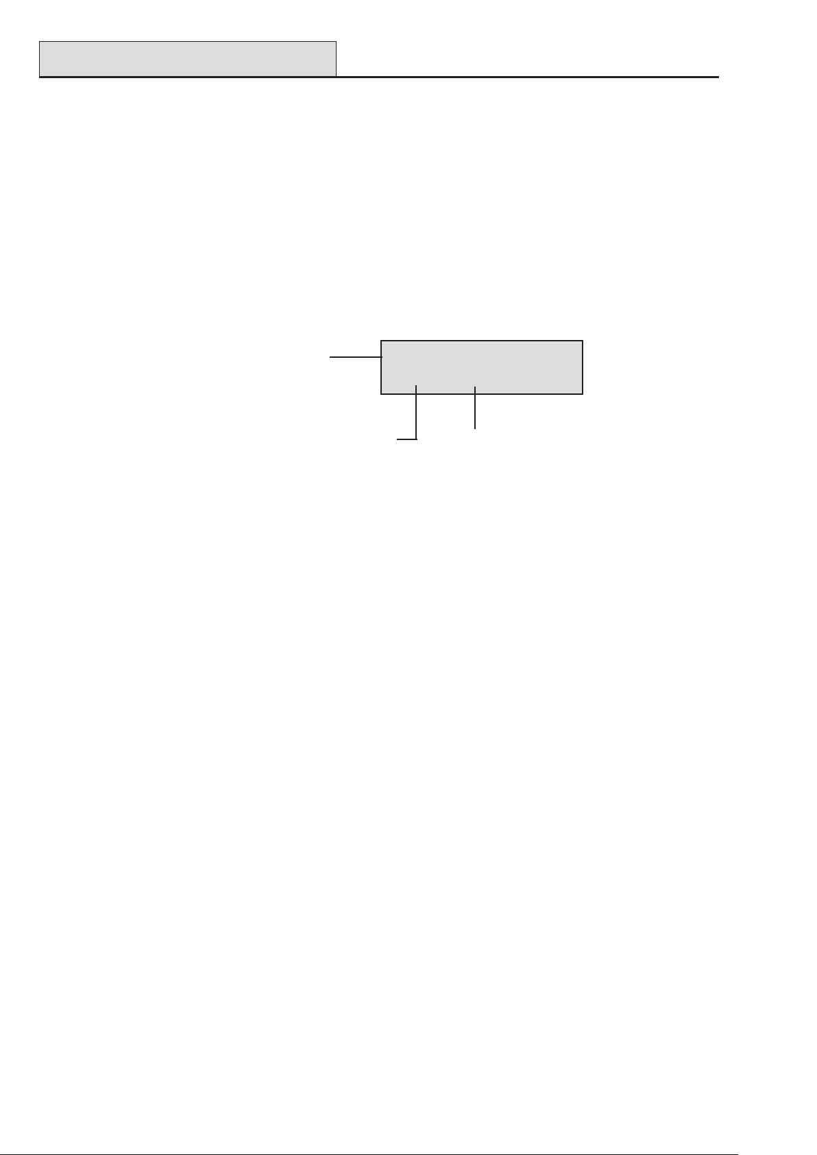
Viewing MAX3 Events
Galaxy 3 Series Installation Manual
MAX3 Log
The Galaxy system has a panel dependent event log for recording the MAX3 activations. This log is shared by
all readers on the system and operates on a first-in-first-out basis for overwriting events when the log is filled.
T o display the events in the MAX3 log select option 25 = ACCESS DOORS; use the A or B keys to select
the required MAX3 address then press the ent key . The first event that occurred on the selected MAX3 is
displayed along with details of the time, date and MAX3 number.
To view the log press the A key to move forward in time through the events or the B key to move
backwards. Press the esc key to return to the MicroMAX address display . T o view the log of another
MAX3, use the A or B key to select the required address. T o escape from the Access Doors option press
the esc key.
Time and date
of event
MAX3 user number Event type
MAX3 Events Print-Out
The MAX3 events can be printed out as they occur to an on-line printer. T o print the MAX3 events ensure
that option 51.27 = P ARAMETERS.On-Line Print is enabled. Select option 51.28 =
P ARAMETERS.On-Line Level and enter 2 to print out all system events including the MAX3 events or 3
to print out only the MAX3 events.
NOTE: A serial printer must be connected to line one of the Galaxy panel and the printer must remain on-line
(ready to print) at all times.
02:25 SUN 22 OCT02:25 SUN 22 OCT
02:25 SUN 22 OCT
02:25 SUN 22 OCT02:25 SUN 22 OCT
USR032 ValidUSR032 Valid
USR032 Valid
USR032 ValidUSR032 Valid
Downloading the MAX3 Log
The MAX3 event log can be downloaded to Galaxy Gold by using the MAX Log copy option in Galaxy
Gold.
5-6
Page 65

Galaxy 3 Series Installation Manual
Dual Card Access/Focus
Dual Access Cards
If a user’s card number is assigned a *, then the card becomes Dual access. This means that it will not open
the door on its own; it needs another PIN or card as well. If the PIN belonging to the same user has a #
assigned, then that PIN must be entered first before access will be granted to that card.
If the PIN has no # assigned, then the card will work only in conjunction with any other Dual Access card that
shares one or more groups (see option 42 = Codes for programming).
Dual Focus (Card Held)
If a card has a # assigned to the number, then any card-held function will only work in conjunction
with the PIN from the same user, provided that the PIN has a # assigned also. The Dual Focus function
will work in either order, but if the card is presented first, it will simply enable the PIN to gain access
to the normal menu (see option 42 = Codes for programming).
Timed Anti-Passback
When the Timed Anti-Passback feature is enabled, it will prevent more than one use of any particular card at a
particular reader within a given time period. See option
63.2.3.6 = Options.MAX.Max Parameters.Anti-Passback for programming details.
A forgiveness function is available to clear all or particular antipassback restrictions in force. There are
set Anti-Passback users as defined in the following Table. If a card belonging to one of these users is
swiped at a reader, all anti-passback restriction at that reader are cleared. A manager code can authorise
a forgive function on a particular user in option 42.1 = Codes.User Codes. An engineer code can
authorise a forgive function on a particular reader in option 63.2.3.6 = Options.MAX.Max
Parameters.Anti-Passback.
5-7
Page 66

Galaxy 3 Series Installation Manual
5-8
Page 67

Galaxy 3 Series Installation Manual
Installation Instructions
Appendix A : Door Control - MAX (MX01)
Installation Instructions
The MAX box contains the following:
• MAX reader (P/N MX01),
• MAX facia label (P/N 21_1627),
• 10-way connector block.
The MAX installation sequence is as follows:
1. Wiring the MAX
2. Mounting the MAX
3. Attaching the facia label
Wiring the MAX
N/O
COM
N/C
Horn
Egress
Contact
B
A
-VE
+VE
Connected to the Door
}
Strike as per manufacturer's
requirements and instructions
Horn
MAX by-pass
Door contact
AB bus of Galaxy
0V
+12V
12V
0V
0V
Figure A-1 MAX Wiring Details
1. Connect the A and B lines of the Galaxy communication bus to the A and B terminals. This
configuration must be a daisy-chain (parallel) connection. If the MAX is the last module in the
line, then the End of Line (EOL) resistor must be connected across the A and B terminals.
2. Connect the door strike in accordance with the manufacturer’s recommendations, via the relay.
3. The Horn output is an open collector. This is connected to the output device via a relay.
NOTE: With MAX software version 1.23 the horn output does not function when the reader is
programmed as on-line operating mode.
4. The Egress switch is used to activate the door strike, allowing the door to be opened without
activating the horn (the egress switch is normally open).
5. The Contact switch is used to connect the access door to an alarm contact, giving alarm indication
when the door is opened without the door strike being activated (either by a MAX card or the
egress switch).
6. Connect a 12 Vd.c. power supply to the MAX terminals marked –VE and +VE.
A-1
Page 68

Installation Instructions (cont’d)
)
Galaxy 3 Series Installation Manual
Mounting the MAX
Attach the wired-up 10-way connector block to the pins on the rear of the MAX reader.
Surface Mounting the MAX
1. If the wiring is not wall recessed, remove the appropriate knock-out (from the sides, top or bottom
of the MAX).
2. Using the MAX reader as a template locate the two mounting screws in the required positions.
NOTE: The MAX is positioned with the 2 LEDs at the top of the module.
3. Securely attach the module to the wall with 2 No.8 roundhead 2 inch screws.
Flush Mounting the MAX
1. Using the template on the lid of the MAX flush mounting kit box (P/N MX02), locate the position
of the screws and mark and cut-out the recess area required.
NOTE: Ensure that there is sufficient wall surface to securely fix the screws.
2. Fit the MAX reader into the flush mounting kit; push the reader in from the rear ensuring that the
four retaining arms on the flush mounting kit click into place
3. Securely attach the module to the wall with 2 No.8 roundhead 1½ inch screws.
NOTE: The MAX is positioned with the 2 LEDs at the top of the module.
Remove the backing from the facia label, line up the label images with the 6 LEDs and place it on the
face of the MAX.
LED 1 (green)
door strike open
LED 3 (red)
add mode
LED 2 (red)
door closed
LED 6 (red)
programming mode
LED 4 (red)
void mode
Figure A-2 MAX LED’s
MAX
LED 5 (red)
Nightlock mode
A-2
Page 69

Galaxy 3 Series Installation Manual
Configuring a MAX Reader
Configuring a MAX Reader into the System
MAX readers can only be configured into the Galaxy system from engineer mode.
NOTE: When adding a MAX reader to a Galaxy panel ensure that there are no more than eight MAX
readers connected to the RS485 (AB) line.
Wire the MAX as per the instructions given with figure 5-1 then access engineer mode.
The MAX reader must be assigned as either an On-Line or a Stand-Alone module using option 63.2.2
= OPTIONS.MAX.MAX Address:
0 = On-Line: The MAX is fully integrated with the Galaxy system and communicates via the AB
line, sharing system resources and facilities.
1 = Standalone: The MAX operates as an entirely independent unit. The Galaxy does not monitor
the MAX for alarms, tampers or power failure.
NOTE: Early versions of MAX readers cannot convert between the stand-alone and on-line operating
modes:
• MX01S (software V1.23) is a dedicated stand-alone reader. This cannot be converted to
on-line mode and must not be connected to the Galaxy AB line. The horn output is fully
functional.
• MX01 (software V1.23) is programmed as an on-line reader. The horn output is non-
functioning. The reader can be reprogrammed, via the Galaxy system, into stand-alone
mode, however, once programmed as stand-alone it cannot be converted to on-line mode.
In stand-alone mode the horn output is fully functional.
• MX01 (software V1.32) can be reprogrammed as stand-alone or on-line as often as
required. In on-line mode, the horn output is non-functioning; in stand-alone mode the horn
output is fully functional.
Configuring as a Stand-Alone MAX
1. Ensure that the MAX is connected to the Galaxy (RS485 AB line) and the MAX mode is enabled
(option 63.2.1 = OPTIONS.MAX.MAX Mode).
2. Select option 63.2.2 = OPTIONS.MAX.MAX Address and press the ent key; the Galaxy
searches for the MAX with the highest address (the new MAX reader). The Galaxy 500 and 512
prompt for the AB line (1 – 4) that is to be searched; select the line and press the ent key. On
locating the MAX address, the keypad prompts for the OPERATING MODE of MAX to be assigned:
select 1 = Standalone and press the ent key. The MAX reader is readdressed as 32.
When the reprogramming is complete the MAX bleeps, LED 2 on the MAX switches on and the
keypad display returns to 2 = MAX Address.
3. (MAX software versions 1.23 and 1.32) Disconnect the AB line from the MAX reader. Ensure
that all other modules (keypads, RIOs and on-line MAX readers) are still daisy-chained into the
Galaxy panel. If the MAX reader is the last module on the AB line, remove the 680Ω end of line
resistor and put it into the last module on the line.
NOTE: The Galaxy cannot operate if the AB line is connected to stand-alone MAX readers with
software V1.23 or V1.32.
4. The MAX reader is now programmed as a stand-alone module in sleep mode (LEDs 2 – 5 on) and
can be programmed using the MAX cards (refer to Programming Stand-Alone MAX Readers).
A-3
Page 70

Configuring On-Line MAX
Galaxy 3 Series Installation Manual
Configuring as On-Line MAX
1. Only if reprogramming an existing stand-alone MAX reader:
• Put the MAX reader into the sleep mode (present the Void Master card then swipe twice with
the Program Master card — LEDs 2 – 5 switch on. Refer to the MAX Installation and
Operations Guide (L120).).
• Remove the power from the MAX reader.
2. Connect the AB line of the MAX reader to the AB line from the control panel (ensuring that a
daisy-chain connection is maintained and that the 680Ω resistor is located in the last module on the
line). Connect 12 Vd.c. to the +VE and –VE terminal of the MAX reader.
3. Ensure that the MAX mode is enabled (option 63.2.1 = OPTIONS.MAX.MAX Mode).
4. Select option 63.2.2 = OPTIONS.MAX.MAX Address and press the ent key; the Galaxy
searches for the MAX with the highest address (the new MAX reader). The Galaxy 500 and 512
prompt for the AB line (1 – 4) that is to be searched; select the line and press the ent key.
Only if adding a new MAX reader: On locating the MAX address, the keypad prompts for the
OPERATING MODE of MAX to be assigned: select 0 = On-Line and press the ent key.
NOTE: If reprogramming an existing stand-alone reader, the system automatically selects the On-
Line operating mode
The MAX can then be readdressed. The keypad displays the current address of the MAX and the
range of valid addresses. Enter the new MAX address and press the ent key; the Galaxy then
reprograms the address of the MAX. The keypad indicates the old and new MAX addresses and
the status of the reprogramming.
NOTE: All new MAX readers default to address 7. It is recommended that when adding a reader,
it is addressed as the lowest available number on the line.
When the reprogramming is complete the MAX bleeps, the LEDs on the MAX switch off and the
keypad display returns to 2 = MAX Address.
NOTE: If the Galaxy has been warm-started with the MAX connected and the reader is re-
programmed with its existing address, then the LED does not switch off and engineering
mode does not have to be exited to configure the MAX into the system.
5. Program the MAX Parameters. This option defines the operational features of the MAX reader.
1 = Descriptor: This option is used to assign a name of up to 12 characters to each of the MAX
modules.
2 = Open Timeout: This is the period, following the user card swipe, that the MAX relay is
activated allowing a door strike to be unlocked and the door to be opened without creating an
alarm. The MAX relay de-activates as soon as the door is closed or the Close Timeout occurs.
3 = Close Timeout: This is the period following the user card swipe that the door can remain open
when gaining access. If the door remains open longer than the period assigned to the Close
Timeout, then an alarm occurs.
4 = Groups: Each MAX module can be assigned to selected groups; the MAX then responds only
to cards that have a group common to it.
A-4
Page 71

Galaxy 3 Series Installation Manual
Keypad Group Restriction: To restrict the operation of the function only to groups that are
common to both the card and the MAX, press the key when assigning groups to the MAX.
This means that when a card with access to groups 1, 2 and 3 activates the MAX card function
on a MAX module assigned to groups 2, 3 and 4, the function only operates on the common
groups (groups 2 and 3).
6. Exit engineer mode — engineer code + esc: the keypad displays the message 1 MOD. ADDED —
esc=CONTINUE. LED 2 on the MAX reader switches on. Press the esc key; the keypad returns to the
unset banner .
If this message is not displayed, the MAX reader is not communicating with the control panel and has not
been configured into the system (LED 2 does not switch on).
NOTES:
1. The MAX reader will not operate until engineer mode is exited and the reader is configured into the
system.
2. All MAX doors must be closed, otherwise engineer mode cannot be exited.
Removing MAX Readers
7. The on-line MAX reader is now configured into the system
Removing a MAX Reader from the System
Stand Alone Mode
The stand-alone MAX reader is not connected to the AB line, therefore it can be removed simply by
disconnecting the power to the reader. There is no requirement to access engineer mode.
On-Line Mode
1. Access engineer mode.
2. Disconnect the MAX reader (AB line and power).
3. Exit engineer mode.
The message 1 MOD. MISSING — [<],[>] to View is displayed.
4. Press the A or B key.
The message MAX X —
5. Press the key to acknowledge and accept that the MAX reader has been removed. The keypad
returns to the unset banner.
=REMOVE MODULE is displayed.
Programming Instructions for On-Line Readers
Refer to Section 6: System Operation, menu option 63 = OPTIONS for details on programming the
Open Timeout, Close Timeout and Group parameters for the MAX reader.
NOTE: These programming instructions refer only to on-line MAX readers (modules that are
connected to a host Galaxy panel via the RS485 data bus). For details on stand-alone MAX
installation refer to the MAX Installation and Operations Guide (L120).
For details on the programming of the MAX user cards and functions refer to Section 6: System
Operation, menu option 42 = CODES.
A-5
Page 72

Operating Instructions
Galaxy 3 Series Installation Manual
Operating Instructions (On-Line Modes)
The MAX must be presented with a valid user card to allow access. Opening the door while LED 2 is
on activates an alarm; the buzzer sounds and LED 1 flashes until the door is closed.
Activating the egress switch allows the door to be opened without activating an alarm when no card
has been presented to the MAX.
Gaining Access
1. Ensure that LED 2 is on and all other LEDs are off.
2. Swipe the MAX with a standard user or nightlock access user card. LED 2 switches off and LED 1
switches on for the programmed Open Timeout.
3. Open the door while the LED 1 is on and access the area.
4. Close the door; LED 1 switches off and LED 2 switches on. The door must be closed within the
programmed Close Timeout; if the door remains open longer than this, an alarm is activated.
Nightlock Access (Stand-Alone Only)
Only cards programmed as nightlock access users can gain access when the MAX is nightlocked. The
operation is identical to the standard user card.
NOTE: Access cannot be gained using a standard user card.
Card-Held Function
The MAX card can be assigned a single menu option (refer to option 42.2.8 = CODES.User
Codes.MAX Function). To activate the function assigned to the MAX card, hold the card in front of
the reader for three seconds; all of the LEDs switch on. If a keypad has been assigned to the MAX
function then it displays the details of this option. If no keypad is assigned, pressing a key on any of
the keypads assigned to a common group to the user displays the card-held function.
Card-Held System Setting
If the MAX card is assigned one of the setting options (option 12, 13, 14 & 16 – 19), the card-held
functions starts the setting procedure for the groups assigned to the card.
NOTE: If Group Restriction is assigned, then only the groups that are common to both the MAX
reader and the MAX user are set.
If all of the groups that are assigned to the MAX are set (either by the card-held function or by any
other setting means) all of the LEDs switch off.
To unset the system using the MAX, swipe the reader with a valid MAX card. The MAX reader beeps
and LED 2 switches on. All of the groups assigned to the MAX are instantly unset.
A-6
Page 73

Galaxy 3 Series Installation Manual
Viewing Max Events
Max Log
The Galaxy system has a 1000 event log (500 for 3-48) for the recording the MAX activations. This log is
shared by all readers on the system and operates on a first-in-first-out basis for overwriting events when the
log is filled.
T o display the events in the MAX log select option 25 = ACCESS DOORS; use the A or B keys to select
the required MAX address then press the ent key . The first event that occurred on the selected MAX is
displayed along with details of the time, date and MAX number .
To view the log press the A key to move forward in time through the events or the B key to move
backwards. Press the esc key to return to the MAX address display. To view the log of another MAX,
use the A or B key to select the required address. To escape from the Access Doors option press the
esc key.
Time and date
of event
Max user number
02:25 SUN 22 OCT02:25 SUN 22 OCT
02:25 SUN 22 OCT
02:25 SUN 22 OCT02:25 SUN 22 OCT
USR032 ValidUSR032 Valid
USR032 Valid
USR032 ValidUSR032 Valid
Event type
Max Events Print-Out
The MAX events can be printed out as they occur to an on-line printer. To print the MAX events
ensure that option 51.27 = PARAMETERS.On-Line Print is enabled. Select option 51.28 =
PARAMETERS.On-Line Level and enter 2 to print out all system events including the MAX events
or 3 to print out only the MAX events.
NOTE: A serial printer must be connected to line one of the Galaxy panel and the printer must remain
on-line (ready to print) at all times.
A-7
Page 74

Galaxy 3 Series Installation Manual
A-8
Page 75

Galaxy 3 Series Installation Manual
Smart PSU
Appendix B: 3 Ampere Smart PSU - P015
The Galaxy Smart PSU can be connected to the Galaxy control panels. The Smart PSU integrates a three
ampere power supply with an eight zone Galaxy RIO. This can be used in place of a standard RIO to overcome power problems that arise when the additional RIO is fitted distant to the control panel.
The connection, addressing, zones and outputs information is identical to that described in the previous Re-
mote Input Output (RIO) Modules sub-section.
Comms
+
-
Socket
Comms
Line
Tamper
Outputs
12V2
12V1
O/P
A
S1
B
A
B
T
-
+
-
+
4
3
21
F4 (1.6 A)
R23
R33
R37
R43
HEATSINK
F3 (1.6 A)
LED
PROCESSOR
3k3Ω pull-up
resistors
Rotary
Address
Switch
AC
Connector
LK3
Batt F2
LK2
(2.5 A)
-
+
3
1
1/2
2
3/4
4
Zones 1-8
5/6
5
8
7/8
6
7
Rev 0.8
Figure B-1. Galaxy 3A Smart PSU
NOTE: The number of pull-up resistors may vary with different hardware revisions.
Grounding
The 0V on the Galaxy system is connected to earth via mounting screws on the Smart PSU. The 0V must be
connected to earth at the main control panel only . If a smart PSU is being used remotely , an insulating washer
should be fitted behind the head of the top left mounting screw .
The integrated RIO has eight programmable zones and four programmable outputs. It is programmed and
operates in exactly the same way as the standard Galaxy RIO. The Smart PSU has two separately fused
regulated 12 Vd.c. outputs, each capable of supplying one ampere to additional modules and devices. A
fused regulated voltage is also supplied to charge a 12 volt lead-acid stand-by battery .
For further information refer to Galaxy Smart Power Supply Unit Installation Instructions (II1-0101).
The default functions and pull-up resistors of each Smart PSU output, when connected to a Galaxy are shown
in the following T able:
.oNtuptuOnoitcnuFrotsiseRpu-lluP
1slleB34R
2ebortS73R
3AP33R
4teseR32R
T able B-1. Smart PSU Output Default Functions
NOTE: The number of pull-up resistors may vary with different hardware revisions.
B-1
Page 76

Galaxy 3 Series Installation Manual
B-2
Page 77

Galaxy 3 Series Installation Manual
Appendix C: Panel Comparisons
Gala xy G3 P a nel
3-48 3-144 3-520*
Panel Comparisons
Zones (on board to max)
Zone types
Outputs (on board to max)
Output Ty pes
User Codes
Groups
Muti-Users
Event Log
MAX Log
Links
7-Day Timers
Autoset
Timed Lockout
Pre-Check
Part Set
16 to 48 (16 on board) 16 to 144 (16 on board) 16 to 520 (16 on board)
49 49 49
8 to 24 8 to 72 8 to 260
76 76 76
100 250 999
4832
4816
1000 1500 1500
500 1000 1000
64 128 256
22 2
20 On/Off (per group) 20 On/Off (per group) 20 On/Off (per group)
Yes Yes Yes
Yes Yes Yes
Yes Yes Yes
Library (Words)
RS485 Lines
RIO's
Output Module
Keypads
Keyprox
MAX's
RS232 Module Support
Printer Module Support
Telecom Module Support
Remote Servic ing
Ethernet Module Support
ISDN Module Support
RF RIO
538 538 538
12 4*
4 8 per line
4 4 per line 4 per line
8 8 per line 8 per line
3
4 4 per line 8 per line
on-board + 1 optional on-board + 1 optional on-board + 1 optional
on-board + 1 optional on-board + 1 optional on-board + 1 optional
on-board + 1 optional on-board + 1 optional on-board + 1 optional
Yes Yes Yes
Optional Optional Optional
Optional Optional Optional
Optional Optional Optional
7 (3 line 1)
(4 line 2)
63 (15 line 1)
(16 lines 2, 3, 4)
24 (3 line 1)
(7 lines 2, 3, 4)
* The Galaxy 520 requires an additional plug-on module in order to provide two additional RS485 lines.
C-1
Page 78

Galaxy 3 Series Installation Manual
C-2
Page 79

Galaxy 3 Series Installation Manual
Approvals
Appendix D: Declaration of Conformity
Compliance and Approvals
The Galaxy 3 Series control panels are compatible with the relevant parts of the following standards:
• PD6662:2003 Scheme for the application of European Standards for intruder alarm
systems.
• EN50131-1:2003 Draft 9d Alarm systems - Intrusion systems - General requirements (grade 3).
• TS50131-3 Alarm systems - Intrusion systems: Part 3 Control and indicating
equipment (grade 3).
• prEN50131-5-3 Alarm systems - Intrusion systems: Part 5-3 systems using wire-free
interconnections (grade 2).
• EN50131-6:1998 Alarm systems - Intrusion systems - Power supplies (grade 3).
• EN50136-1-1:1998 Alarm systems - Alarm transmission systems and equipment - General
requirements for alarm transmission systems.
• EN50136-1-3:1998 Alarm systems - Alarm transmission systems and equipment -
Requirementsfor systems with digital communicators using the public
switched telephone network.
• EN50136-2-1:1998 Alarm systems - Alarm transmission systems and equipment - General
requirements for alarm transmission equipment.
• EN50136-2-3:1998 Alarm systems - Alarm transmission systems and equipment -
Requirementsfor equipment used in systems with digital communicators
using the public switched telephone network.
• CE Standards, including all EN safety and EMC standards.
• R&TTE 99/5/EC
• BS6799:1986 Code of practice for wire-free intruder alarm systems.
• DD243:2002 Installation and configuration of intruder alarm systems designed to
generate confirmed alarm conditions - code of practice.
• BSIA Guidelines for Remote Maintenance to systems installed to EN50131-1
D-1
Page 80

Approvals (cont’d)
Galaxy 3 Series Installation Manual
EN50131 Compliance
This product is suitable for use in systems designed to comply with PD6662:2004 and prEN50131-1: 2004/6
Security Grade: 3
Environmental Class: II
Power Supply T ype: A
The built-in T elecom module is for Remote Servicing use only on Grade 3 systems. An external Grade 3
communicator or Ethernet module must be used for alarm signalling.
The built-in T elecom module can be used for alarm signalling on Grade 2 systems:
Alarm Transmission System: 2 (options A, B, C & X)
This product is suitable for use in systems designed to comply with EN50131-1: 1997
Security Grade: 2
Environmental Class: II
Alarm Transmission System: 2 (options D2, T2, A2, S0, I0)
Power Supply T ype: A
PD6662 Compliance
This product is suitable for use in systems designed to comply with PD 6662:2004 at grade 3 and environmental class II.
Public Switched Telephone Network (PSTN) approval
The equipment has been approved to Council Decision 98/482/EC for Pan -European single terminal connection to the Public Switched T elephone Network (PSTN). However due to differences between the individual
PSTNs provided in different countries the approval does not, of itself, give an unconditional assurance of
successful operation on every PSTN network termination point.
In the event of problems contact the equipment supplier in the first instance.
The Galaxy is designed to interwork with the following networks:
Austria France Italy Norway Switzerland
Belgium Greece Liechtenstein Portugal United Kingdom
Denmark Iceland Luxembourg Spain * Germany
Finland Ireland The Netherlands Sweden
* May have interworking difficulties.
NOTE: Contact the equipment supplier before using the Galaxy on any network not listed.
D-2
Page 81

Galaxy 3 Series Installation Manual
Specifications
Appendix E: Specifications
Panel Specifications
Mechanical (all variants)
Enclosure (with PCB and transformer) W idth: 440 mm
Height: 352 mm
Depth: 88 mm
W eight: 6.4 kg
Physical space for batteries 2 x 17Ah Max (not suitable for 12Ah batteries)
PCB only Width: 265 mm
Height: 120 mm
Depth: 47 mm
W eight: 0.3kg
Operating temperature: -10 deg.C to + 55 deg.C
Electrical
Mains input: 230V ac (+10%/-15%) @ 50 Hz
Power supply: T ype A
(G3-48) T otal capacity 1.5A (0.75A dedicated to battery)
Operating temperature: -10 deg.C to +40 deg.C
Power supply: T ype A
(G3-144/520) Total capacity 2.5A (1.25A dedicated to battery)
Operating temperature: -10 deg.C to +40 deg.C
Auxiliary +12V outputs: 12V nominal
(G3-48) 0.5A in total
50.0 mV maximum ripple
Auxiliary +12V outputs: 12V nominal
(G3-144/520) 1.0A in total
50.0 mV maximum ripple
Fuses
AUX1 1.0A - 20 mm anti-surge
AUX2 1.0A - 20 mm anti-surge
BELL 1.0A - 20 mm anti-surge
BA TT (G3-48) 1.0A - 20 mm anti-surge
B AT T (G3-144/520) 1.6A - 20 mm anti-surge
NOTE: Fuse AUX2 is not required on the G3-48.
PSTN V.22 Modem 1200 Baud
RS232 300 - 56k programmable
RS485 9600 Baud, Full Duplex, Asynchronous
E-1
Page 82

Specifications (cont’d)
Modules Weight Order Code
Galaxy Keypad (Mark VII)......................................................................190 g CP027
Size: …………………………………................. 149 x 91 x 31 mm (L x B x H)
Galaxy Keyprox (Mark VII).....................................................................190 g CP028
Size........................................................................149 x 91 x 31mm (L x B x H)
Keypads Material ................................................................................... PC + ABS
Keypad Colour....................................................................................... Neutral
Galaxy RIO (Boxed) .................................................................................300 g C072
Size: ......................................................................150 x 162 x 39 mm (L x B x H)
Galaxy RF RIO (Boxed) ................................................................... 270 g C076
Size ............................................................. 150 x 162 x 39 mm (L x B x H)
Galaxy Output Module (Boxed)....................................................... 270g C078
Size ............................................................. 150 x 162 x 39 mm (L x B x H)
Galaxy Relay Module ....................................................................... 22 g A237
Size ....................................................................... 31 x 50 x 20 (L x B x H )
Galaxy 3 Series Installation Manual
RS232 Module (Boxed) .......................................................................... 823 g E054
Size: .....................................................................180 x 155 x 35 mm (L x B x H)
Doorguard ................................................................................................ 995g C075
Size: .....................................................................150 x 185 x 40 mm (L x B x H)
Printer Interface (6-W ay DIN Plug) ......................................................120 g A134
Printer Interface (25-W ay D Plug) ........................................................ 130 g A161
Box Size: .............................................................. 75 x 52 x 2 8 mm (L x B x H)
Cable Size: ............ 2m for 4-W ay IDC, and 0.3m for 6-W ay/25-W ay plug.
PCBs Weight Order Code
2-75A Power Block ................................................................................. 163 g A270
Size: .....................................................................115 x 102 x 33 mm (L x B x H)
Galaxy Power RIO Control......................................................................118 g A250
Size: .....................................................................120 x 120 x 43 mm (L x B x H)
Galaxy Power Unit Control..................................................................... 118 g A251
Size: .....................................................................120 x 120 x 43 mm (L x B x H)
PSU Control..............................................................................................118 g A252
Size: .....................................................................120 x 120 x 43 mm(L x B x H)
Galaxy 3-144C........................................................................................... 320 g A3045-01
Size:......................................................................265 x 120 x 50 mm (L x B x H)
Galaxy 3-520C (with Expander) ............................................................. 378 g A307-01
Size:.....................................................................265 x 120 x 50 mm (L x B x H)
Galaxy 3-144 ..................................................................................... 320 g A304-01
Size:......................................................................265 x 120 x 50 mm (L x B x H)
Galaxy 3-520 (with Expander)................................................................ .378 g A306-01
Size:......................................................................265 x 120 x 50 mm (L x B x H)
E-2
Page 83

Galaxy 3 Series Installation Manual
Specifications (cont’d)
PCBs Weight Order Code
Galaxy RIO ............................................................................... ....... 92 g A158
Size: .............................................................................. 121 x 90 x 15 mm (L x B x H)
Galaxy RF RIO .......................................................................... ....... 63 g A215
Size: ............................................................................. 121 x 97 x 12 mm (L x B x H)
RS232 ...................................................................................................... 124 g A169
Size: .............................................................................. 135 x 90 x 17 mm (L x B x H)
T elecom.................................................................................... ....... 90 g E062
Size: .............................................................................. 121 x 90 x 20 mm (L x B x H)
Ethernet.................................................................................... ....... 56 g E080
Size: .............................................................................. 121 x 90 x 15mm (L x B x H)
ISDN ........................................................................................ ..... 114 g A211
Size: .............................................................................. 121 x 90 x 15 mm (L x B x H)
Note: The above weights and order codes are from the populated Printed Circuit Board (PCB) only .
Device Quiescent Current
(mA)
Galaxy 3-48C 150 RS232 Module (E054,
E055)
Galaxy 3 -14 4 150 4-Way R elay Inter f ace
(C037)
Galaxy 3-144C 150 General Purpose
Relay Interface (A060)
Galaxy 3 -52 0 150 Galaxy M k 7 (LCD)
Keypad
Galaxy 3-520C 150 Key Prox 90
Galaxy RIO (Note 1) 40 P rinter Interface
(A134/A161)
RF RIO 55 D o o rg uard (C07 5 ) 10
Output Module 45 Max Reader 35
Device Quiescent Current
(mA)
50
160
40
55
100
3 A Smart PSU (Note 1) 100 MicroMAX 25
Smart PSU G3
Standalone
Telecom Module (E062)
(Note 2)
T able E-1 Current Consumption
Note 1: Measured with no load on zone input
Note 2: Not communicating
ISDN Modu le 40
45 Ethernet 155
E-3
Page 84

Galaxy 3 Series Installation Manual
E-4
Page 85

Galaxy 3 Series Installation Manual
Appendix F: Parts List Index
Parts List Index
Produ ct N am e UK Part No Comments
Replacement PC B,s
Galaxy 3-48C PCB A348-01
Galaxy 3-144 PC B A30 4-01
Galaxy 3-144C PCB A30 5-01
Galaxy 3-520 PC B A30 6-01 With expander
Galaxy 3-520C PC B A307-01 With expander
Accessories
Doorguard C075 Door isolation
Doorguard c om mon ke y C07 5C All use sam e
Engineer keypad cable A136
Twisted pair 4-core c able W 002
Serial Peripheral interface
Key
PSU ’s
Upgrade Kits
G3-144 to G3-52 0
upgrade
Flash programmer P 02 5
Galaxy Power Unit P025
Galaxy Power RIO P026
EN G 3 P S U Stand-alone P027
2-75A Power Block A270 Spare PCB
Galaxy Power RIO
Control PCB
Galaxy Power Unit
Control
PSU Control A252 Spare PCB
Keypad /Key Pro x
Galaxy Mk 7 Keyp ad CP03 7 W ith volume
Galaxy Mk7 KeyProx CP038 ASK f ormat with
Galaxy KeyProx HID C P028-01-H-B ASK/HID format
ASK p rox card clamsh ell YX 0-00 05 C redit card
HID prox c ard YX0- 0006 C r edit card
ASK Keytag YX0-00 04 Tear drop
ASK G r ey F ob YX0-0020
Remote M odu les
RIO (PC B) A158-B
RIO (box ed ) C072
Telecom M odu le E 062-01
RS232 Module E055
RS232 Module (boxed) E054
Printer Interface A134 6 pin DIN
Printer Inte rf ace A161 25 w a y su b D
ISDN M odu le E07 7
Ethernet Module E080-2
RF RIO (b ox ed) C07 6
RF RIO (PCB) A215
Output Mod ule (boxed) C07 8
Ou tp ut Mo d ule K it (PCB ) A 2 3 8
Relay m od ule A 23 7
Access Control
MA X Read er M X 01
MA X Flush m ounting kit M X02
MA X3 P ro xim ity Reader MX03
MAX3 vandal resistant
cover
MA X3 extension read
head
MA X3 hand-h eld
programm er
MA X3 M ounting plate M X 03-MP
MAX card with m agn etic
stripe
A227
A240
A250 Spare PCB
A251 Spare PCB
MX03-VRC
MX03-ERH
MX03-HP
YX0-0001
Unit
key
control
volume c ontr ol
connector
connector
Product Name UK Part N o Comments
MA X c ard YX0-00 02
MA X keytag YX0-0004
MA X program m ing
modu le
Software Packages:
Remote Servicing Suite
Licencing Kit R030 K IT
Upgrade R030-CD
Licence Kit (Don gle) R 03 1-01-KIT
Upgrade (Dongle) R 03 1-C D
User Management Suite
Licence Kit R 03 2-0 1-KIT
Upgrade R032-CD
Licence Kit (Don gle) R 03 3-01-KIT
Upgrade (Dongle) R 03 3-C D
Litera tur e
Galaxy 3 Series
Inst a lla ti o n m a nu a l
Galaxy 3 Series
Programming manual
Galaxy 3 Series User
Guide
Galaxy 3 Series Quick
Guide
YX0-0007
II1-0033
IP1-0033
IU1-0033
IG1-0033
F-1
Page 86

Galaxy 3 Series Installation Manual
F-2
Page 87

Galaxy 3 Series Installation Manual
Index
Index
A
Adding a Keypad/Keyprox
to the System 4-4
Addressing 4-2
Addressing the RF RIO 3 -6
Appendix A: Door Control
(MAX ) A-1
Appendix B: 3 Ampere
Smart PSU B- 1
Appendix C: Panel
Comparisons C - 1
Appendix D: Declaration
of Conformity D- 1
Appendix E:
Specifications E -1
Appendix F: Parts List
Index F-1
B
C
Configuring a MAX
Reader into the System 5-3
Configuring the RIO 3- 2
Connecting Additional
Telecoms apparatus 2-8
Connecting the Galaxy 3
Series to the PSTN 2- 7
Connecting the RIO 3 - 2
Connecting the RF RIO 3-5
Configuring the RF RIO 3-7
D
Dual Access Cards 5-7
Dual Focus (Card Held) 5 - 7
E
Entry/Exit RIO 3-3
Ethernet Module 3-21
Event Monitoring 3-17
F
Fuses 2-7
G
Galaxy Gold 3-21
Galaxy Keypad 4-1
Galaxy Keyprox 4-8
H
3
I
Installing the MAX
Introduction 1-1
ISDN Module 3-19
3
5-1
J
K
Keypad/Keyprox Installation
Procedure 4-2
Keypad/Keyprox Operation4- 5
L
Line Monitoring 2- 8
M
3
MAX
Memory 2-10
5-1
N
O
On-board Power Supply
Unit 2-9
Optional Modules and
Facilities 3-1
Output Module 3-8
P
PCB Layout 2- 4
Power Supply Unit 3-12
Power Consumption 4- 1
Printer Interface Module 3-15
Q
Quick Setup 1 - 3
R
RF RIO 3-5
RS232 Interface Module 3-17
RS 485 Data Communication
Bus (AB Lines) 2-10
RS485 Expansion module 2-3
RS485 Wiring
Configurations 2-10
RS485 Wiring
Recommendations 2-11
Remote Input Output (RIO)
Module 3-1
Remote Servicing Suite 3-21
Removing a Keypad/Keyprox
from the System 4-4
Removing a MAX
Reader from the System 5- 5
3
S
Self Diagnostics 4- 5
Serial Printer Interface 3-18
SPI Header 2-18
Stand-by Battery 2-9
System Architecture 2-1
System Installation
and Wiring 2- 6
T
T elecom Module 3-16
Timed Anti-Passback5 -7
U
User Management Suite 3-21
V
W
Wiring Keypad/Keyprox 4- 2
Wiring Keyswitches 2-15
Wiring T erminator Buttons 2-16
Wiring the MAX
Wiring Multiple Zones 2-15
Wiring Zones 2-14
3
5-2
X
Y
Z
Zones 2-13
Zone addresses 2-13
1-1
Page 88

Galaxy 3 Series Installation Manual
1-2
Page 89

Galaxy 3 Series Installation Manual
1-3
Page 90

Galaxy 3 Series Installation Manual
Honeywell Security (UK 64)
Newhouse Industrial Estate
Motherwell
Lanarkshire
ML1 5SB
UK
II1-0033 Rev 2.0
© Copyright Honeywell Security
1-4
 Loading...