

Page 1

Galaxy 2 Series
Installation Manual
Honeywell Security
Page 2

Page 3

Galaxy 2 Series Installation Manual
Table of Contents
Contents
SECTION 1: INTRODUCTION .................................................................... 1
Optional Peripherals ............................................................................................. 1
Features.................................................................................................................. 2
RF ........................................................................................................................................... 2
Groups................................................................................................................................... 2
Dialler ..................................................................................................................................... 2
SMS Text Messaging............................................................................................................ 2
ProxKeypads ........................................................................................................................ 2
Remote Servicing ................................................................................................................. 2
SECTION 2: QUICK GUIDE ........................................................................ 3
How to Boot up ...................................................................................................... 3
Default Codes......................................................................................................... 3
Menu Access Operation/Navigation .................................................................... 3
How to get in and out of Engineer Mode ............................................................ 3
How to Set/Unset.................................................................................................... 3
How to Restore an Alarm ...................................................................................... 4
SECTION 3: SYSTEM ARCHITECTURE .................................................... 5
SECTION 4: SYSTEM WIRING................................................................... 6
General Information .............................................................................................. 6
Siting ...................................................................................................................................... 6
Ventilation.............................................................................................................................. 6
Cabling .................................................................................................................................. 6
Mains Cable Type ................................................................................................................. 6
Zone and Data Cable Type.................................................................................................. 7
Mains Supply Connection................................................................................................... 7
Equipment Electrical Rating................................................................................. 8
Batteries ................................................................................................................................ 8
Fuses ..................................................................................................................................... 8
i
Page 4

Table of Contents
Galaxy 2 Series Installation Manual
Connecting the Galaxy 2 Series to the PSTN ..................................................... 9
Private Branch Exchange (PBX) Approval........................................................................ 9
REN and SEN Numbers...................................................................................................... 10
SECTION 5: HARDWARE ......................................................................... 11
PCB Layout (2–44+) ............................................................................................. 11
PCB Layout (2–20) ............................................................................................... 12
Zones................................................................................................................................... 13
Zone Links .................................................................................................................................................13
Wiring Zones ............................................................................................................................................. 14
Wiring Keyswitches ................................................................................................................................... 14
Wiring Push-Set Buttons ............................................................................................................................ 14
Zone Addresses ................................................................................................................. 15
Zone Numbering System ..........................................................................................................................15
Outputs................................................................................................................................16
Trigger Header .................................................................................................................... 16
Trig 1-8 .......................................................................................................................................................16
Inputs ......................................................................................................................................................... 17
Supply .......................................................................................................................................................17
Data Buses .......................................................................................................................... 17
RS485 Wiring Configurations .....................................................................................................................17
RS485 Wiring Recommendations .............................................................................................................18
ECP Bus (2–44+ Only) .............................................................................................................................. 19
Built-in Dialler/Modem........................................................................................................ 19
LED’S.................................................................................................................................... 19
Audio Header (2–44+ Only) ...............................................................................................19
GSM Interface (2–44+ Only)............................................................................................... 19
Panel Mounting (Plastic Box)............................................................................. 20
Installation Kit ..................................................................................................................... 20
Removing the Enclosure Lid ............................................................................................ 20
Installing the Enclosure Lid .............................................................................................. 20
Removing and Replacing the Galaxy 2 Series PCB ...................................................... 20
Remove the PCB ......................................................................................................................................21
Replace the PCB.......................................................................................................................................21
Mounting the Plastic Enclosure Base ............................................................................. 21
Fitting the Tamper Spring ................................................................................................. 21
Panel Mounting (Metal Box) ............................................................................... 22
Installation Kit ..................................................................................................................... 22
Removing and Installing the Enclosure Lid ................................................................... 22
Removing and Replacing the Galaxy 2 Series PCB ...................................................... 23
Mounting the Metal Enclosure Base................................................................................ 23
ii
Page 5

Galaxy 2 Series Installation Manual
Table of Contents
Peripherals - Installation, Wiring & Addressing............................................... 24
Configuring ......................................................................................................................... 24
General ................................................................................................................................24
Mk7 LCD Keypad/Keyprox ................................................................................................ 25
Keypad/Keyprox Installation ..................................................................................................................... 25
Mk7 Keypad/Keyprox Addressing ........................................................................................................... 26
Adding a Mk7 Keypad/Keyprox to the System ........................................................................................ 26
Remote Input Output (RIO)................................................................................................ 27
Addressing the RIO ................................................................................................................................... 27
Connecting the RIO ................................................................................................................................... 27
Configuring the RIO ................................................................................................................................... 28
Zones.........................................................................................................................................................28
Outputs ...................................................................................................................................................... 28
Power Supply Unit.............................................................................................................. 29
Configuration .............................................................................................................................................. 29
Installation Instructions ............................................................................................................................... 30
Battery........................................................................................................................................................31
Battery Test ................................................................................................................................................ 31
Specifications ............................................................................................................................................31
EN50131 Compliance ................................................................................................................................ 31
ECP Zone Expander (2–44+ Only).................................................................................... 32
Zone Expander Outputs ............................................................................................................................ 32
Addressing the ECP Zone Expander .......................................................................................................33
5800H RF Receiver (2–44+ Only) ...................................................................................... 33
Installation .................................................................................................................................................. 33
Wiring......................................................................................................................................................... 33
Addressing ................................................................................................................................................ 33
G2 RF Portal ........................................................................................................................ 34
Mounting the Plastic Base ......................................................................................................................... 34
Attaching the PCB......................................................................................................................................35
Addressing the RF Portal .......................................................................................................................... 35
Connecting the RF Portal ..........................................................................................................................36
Configuring the RF Portal ..........................................................................................................................36
Attaching the Plastic Box Lid.....................................................................................................................36
Specifications ............................................................................................................................................36
EN50131 Compliance ................................................................................................................................ 36
6160 Keypad/Keyprox/RFH (2–44+ Only)........................................................................ 37
Installation and Wiring ................................................................................................................................ 37
Addressing the 6160 Keypad ................................................................................................................... 38
Addressing the 6160 Keyprox .................................................................................................................. 38
Addressing the 6160 RFH .........................................................................................................................38
2-Way Audio (2–44+ Only) ................................................................................................. 39
Operation of 2-Way Audio ......................................................................................................................... 40
GSM Module (2–44+ Only) ................................................................................................. 41
Characteristics ........................................................................................................................................... 42
Compliance ............................................................................................................................................... 42
iii
Page 6

Table of Contents
Galaxy 2 Series Installation Manual
SECTION 6: GENERAL OPERATION ...................................................... 43
Galaxy 2 Series Users ......................................................................................... 43
Users.................................................................................................................................... 43
Engineers ............................................................................................................................ 43
General Menu Operation..................................................................................... 43
Full Setting .......................................................................................................................... 44
Part Setting.......................................................................................................................... 44
Night Setting ....................................................................................................................... 45
Cancelling the Setting ....................................................................................................... 45
Unsetting the System ........................................................................................................ 45
Cancelling Alarms and Alerts ........................................................................................... 45
Alert Indication ................................................................................................................... 45
Restoring alarms ................................................................................................................46
Overriding of Faults and Tampers................................................................................... 46
Setting and Unsetting with Keyfobs ................................................................................47
Setting and Unsetting with Keytags or Cards ................................................................ 48
Text Programming.............................................................................................................. 49
Additional Functions ......................................................................................................... 50
Code Tampers ...........................................................................................................................................50
Hot Keys .................................................................................................................................................... 50
SECTION 7: MENU OPTIONS .................................................................. 51
Menu 10 - Setting Options................................................................................................. 51
Option 11 - Omit Zones.............................................................................................................................. 51
Option 12 - Timed Set ............................................................................................................................... 51
Option 13 - Part Set ...................................................................................................................................51
Option 14 - Night Set ................................................................................................................................. 51
Option 15 - Chime...................................................................................................................................... 51
Menu 20 - Display Options ................................................................................................ 52
Option 21 - Zone Status ............................................................................................................................. 52
Option 22 - View Log.................................................................................................................................52
Option 23 - System Version ......................................................................................................................53
Option 24 - Print ......................................................................................................................................... 53
Menu 30 - Test Options...................................................................................................... 54
Option 31 - Walk Test ................................................................................................................................ 54
Option 32 - Output Test .............................................................................................................................. 54
Menu 40 - Modify Options ................................................................................................. 55
Option 41 - Time/Date................................................................................................................................ 55
Option 42 - Users ......................................................................................................................................55
Adding Keyfobs (ECP) .......................................................................................................................................... 57
Adding Keyfobs (RS485) ...................................................................................................................................... 57
Removing Keyfobs ............................................................................................................................................... 57
Adding Keytags or Cards - Mk7 485 Keyprox only ............................................................................................... 58
Adding Keytags or Cards - 6160 Keyprox only ..................................................................................................... 58
iv
Page 7

Galaxy 2 Series Installation Manual
Removing Keytags or Cards - Mk7 485 Keyprox only ......................................................................................... 58
Removing Keytags or Cards - ECP 6160 Tags only ............................................................................................ 58
Option 44 - Mobile Nos ............................................................................................................................. 59
Option 47 - Remote Access ...................................................................................................................... 60
Option 48 - Level 3 Access ....................................................................................................................... 60
Table of Contents
Menu 50 - Engineer 1 Options .......................................................................................... 61
Option 51 - Parameters ............................................................................................................................. 61
Option 52 - Zones ...................................................................................................................................... 73
Option 53 - Outputs....................................................................................................................................79
Option 56 - Comms ................................................................................................................................... 82
Option 57 - System Print ........................................................................................................................... 94
Menu 60 - Engineer 2 Options .......................................................................................... 95
Option 61 - Diagnostics .............................................................................................................................95
Option 62 - Full Test ................................................................................................................................... 96
Option 63 - Options ................................................................................................................................... 97
SECTION 8: RF HINTS AND TIPS............................................................ 99
How to Install RF................................................................................................................. 99
RF Zones ............................................................................................................................. 99
RF Stop Set ......................................................................................................................... 99
RF Diagnostics ................................................................................................................... 99
SECTION 9: FINAL COMMISSIONING ................................................... 100
Final system Test ............................................................................................................. 100
User Information............................................................................................................... 100
SECTION 10: REMOTE SERVICING ...................................................... 101
Telephone Line Set-Up .................................................................................................... 101
Direct Wire Set-Up ............................................................................................................101
Remote Programming ..................................................................................................... 101
SECTION 11: FLASH UPGRADE ........................................................... 102
SECTION 12: PRINTER CONNECTION ................................................. 103
SECTION 13: BELL-BOX CONNECTIONS ............................................ 104
SECTION 14: EVENT LOG LIST ............................................................ 105
v
Page 8

Table of Contents
Galaxy 2 Series Installation Manual
SECTION 15: SPECIFICATIONS ............................................................ 108
SECTION 16: COMPLIANCE AND APPROVALS................................... 110
EN50131 Compliance....................................................................................................... 110
Public Switched Telephone Network (PSTN) Approval ............................................... 110
HONEYWELL SECURITY LIMITED WARRANTY ....................................111
Appendix A: Point ID Comms Triggers................................................ A-1
vi
Page 9

Galaxy 2 Series Installation Manual
Introduction
SECTION 1: INTRODUCTION
The Galaxy 2 Series is a 12-zone intruder alarm control panel. There are 2 variants. The 2-44+ is the full
function version which is expandable to 44 zones. The 2-20 is an entry level version which is expandable to
20 zones. This manual covers both versions. However, certain features are not available on the 2-20 variant.
The following table gives the general specification for both variants.
Specification Feature
Galaxy 2-20 Galaxy 2-44+
Zones 12 expandable to 20 12 expandable 44
Outputs 4+8 expandable to 16 4+8 expandable to 28
Databuses RS485 Only RS485 and ECP
PSU 1A (0.6A @ Grade 2) 1.4A (1A @ Grade 2)
Alphanumeric LCD Keypads/
Alphanumeric LCD KeyProx
RIO (8 zones/4 outputs) 1 4
RF Receiver 2 2
User Codes (PIN and Card) 23 23
Groups 3+1 common group 3+1 common group
Part Set 2 Part Sets 2 Part Sets
Silent Night Set Yes Yes
Zone Types 18 18
O/P Types 23 23
Event Log 384 384
Multi-Users 4 4
Printer Module Optional Optional
PSTN Communicator/Modem On-Board On-Board
GSM Comunicator/Modem - Plug on Option
Serial Port 1 on-board 1 on-board
2-way Voice - Optional
4
4
Table 1. General Specifications
The Galaxy 2 Series requires at least one external keypad for programming and general operation. There are
two main types of keypad available.
Galaxy Mk7 LCD Keypad: This keypad has a 2 x 16 character display and operates on the RS485 data
bus. Optionally, a keyprox version is available. This is a standard Mk7 keypad with a proximity card reader
built in to the lower right-hand corner. The keyprox is for set/unset only.
6160 Full Text Keypad: This keypad has a 2 x 16 character display and operates on the ECP data bus.
Optionally versions are available with built-in prox reader and wireless receiver.
Optional Peripherals
Zone Expander: This gives eight extra hardwire zones and four programmable outputs. Alternatively four
extra hardwire zones and no outputs.
1
Page 10

Introduction (cont’d)
RF Radio Receiver: This allows the control panel to receive signals from wire-free detectors and radio
keyfobs. One radio receiver will allow the panel to assign wire-free detectors to any or all of the 44 detection
zones. However, two receivers can be used to increase coverage.
Proximity Card Reader: This allows users to set/unset simply by swiping a card or tag in front of the reader.
The proximity card readers are built into the housing of the keypads.
RIO/ PSU Control: Up to four RIO’s or PSU’s can be added to the RS485 Bus. Each RIO/ PSU Control
expands the system by eight zones and four outputs.
GSM Module: This module provides mobile telecommunications between the panel and the Alarm Receiving
Center (ARC).
Galaxy 2 Series Installation Manual
Features
RF
The system operates with the 5800 receivers on ECP and/or the RF Portal on RS485. A maximum of two RF
receivers can be fitted to the system (two on the ECP bus, two on the RS485 bus or one on each bus), to
support up to 44 zones. The RF receivers are in addition to the prox keypads on RS485 but in place of ECP
prox keypads.
Groups
Group functionality allows the system to be split into three individual sub-systems that can be set and unset
independently. Additionally there is a fourth common group which will set automatically when all the other
groups have set. It is unset as soon as any one group has been unset by a user. Zones are assigned users to a
single group only. Users are assigned to one or more groups.
Dialler
The system can have two active comms devices configured, chosen from:
• On-board PSTN/Modem
• Plug-on GSM Module
These are used for Dial-up primary and secondary signalling, as well as remote servicing and two-way audio.
SMS Text Messaging
This is a secondary alarm notification to keyholders. Text messages are sent to GSM mobile phones, giving
information on panel events.
ProxKeypads
These are standard keypads with an added proximity card reader, combined into one housing. This allows
dual function setting/unsetting ability from the one station without the need for a separate card reader. They
are primarily intended for use in situations where a PIN card is needed to set and unset the intruder alarm
system.
Remote Servicing
The Galaxy 2 series control panel can be remotely and/or locally serviced by a Personal computer (PC). This
is accomplished when the Remote Servicing Software is installed on the PC.
2
Page 11

Galaxy 2 Series Installation Manual
Quick Guide
SECTION 2: QUICK GUIDE
How to Boot up
Wire up the keypads, address them (see Peripherals - Installation, Wiring and Addressing), then apply power
to the system. The keypads will configure and show the default banner display.
GalaxyGalaxy
Galaxy
GalaxyGalaxy
09:51 SAT 01 JAN09:51 SAT 01 JAN
09:51 SAT 01 JAN
09:51 SAT 01 JAN09:51 SAT 01 JAN
44 V1.0 44 V1.0
44 V1.0
44 V1.0 44 V1.0
Default Codes
Default User Code: 1234
Default Engineer code: 112233
Menu Access Operation/Navigation
Only valid codes can access the Galaxy 2 Series menu options.
Type the code then press ent to access the menu.
Data entry, on both ECP and RS485 keypads, is via the 0-9 function keys and the *, # on the keypad.
The A> and <B keys are curser or scroll keys and are used to scroll through options in menus.
The ent key is used to enter a PIN code and to accept screen information.
The esc key is used to cancel or exit from the current operation.
NOTE: Users cannot view or access options for which they are not authorised.
How to get in and out of Engineer Mode
Entry to engineer mode is authorised by a user in menu option 48 = Level 3 Access. Following this the
engineer will have five minutes in which to enter his code. When the engineer code is entered four things
happen:
• All system tampers become isolated.
• All fault signalling is suppressed, and indications are silent.
• The engineer is given access to the full menu.
• The banner message is changed to indicate engineer mode.
To bring the system back out of engineer access mode and reinstate all the tampers from the banner, the
engineer enters his code but presses the esc key rather than the ent key.
How to Set/Unset
To Full Set the system, the user types their code then presses the A key.
To Part Set the system, the user types their code, presses the B key then presses the [1] key.
To Night Set the system, the user types their code, presses the B key then presses the [2] key.
To Unset the system, the user types their code then presses ent.
3
Page 12

Quick Guide (cont’d)
Galaxy 2 Series Installation Manual
How to Restore an Alarm
Alarms, faults and tampers will be restored provided:
1. The cause has cleared
2. An authorised user PIN code or anti-code has been entered.
3. The conditions have been viewed on the keypad display after steps 1 and 2 above.
If a user cannot restore all the conditions, a temporary banner is displayed to indicate that a manager or
engineer is required to restore the system. This lasts for 30 seconds before the normal banner is displayed.
4
Page 13
Galaxy 2 Series Installation Manual
12 on-board zones
Galaxy 2-44
PCB
Trigger
Header
12-way ribbon cable
External
Communicator
ECP BUS (2 44+ only)
4 outputs
Phone line
Serial Port to PC
Maximum cable length
from panel to last module
on line is 100m
6160 keypad (4)
(optionally with
built-in
receiver/keyprox)
Note: maximum of
2 receivers/keyproxes
ECP zone expander
8 zone, 4 output (3)
5800 RF
receiver (2)
Standard 4-core cable
spurred or T wired
Note: A maximum of 4 keypads
(including keyprox) can be
connected to the RS485 line.
GALAXY 44 V1.0
09:51 01/08/04
1
2
3
A
4
5
6
B
7
8
9
ent
*
0
#
esc
Mk7 LCD
Keypad/Keyprox
(4)
RF Portal (2)
8 zones
4 outputs
8 zones
4 outputs
Power Unit (4) P025
or
Power RIO (4) P026
RIO (4)
C072
OR
RS485 BUS
Twisted pair screened cable
Belden 8723 equivalent.
Daisy chain configuration only.
Maximum cable length
from panel to last module
on line is 1km
Architecture
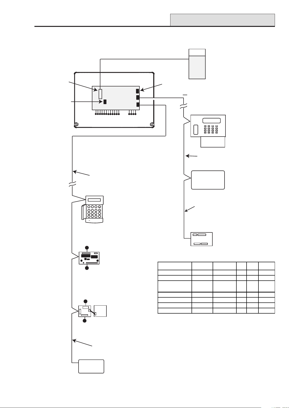
SECTION 3: SYSTEM ARCHITECTURE
Figure 1. Galaxy 2 Series System Configuration
MODULE
Keypads 4 0,1, 2, 3 4 4
Keyprox 4 0,1, 2, 3 2 2
Expanders* 4 on RS485
RF Receivers 2 4, 5 2 2
PSU Control/RIO 4 2, 3, 4, 5 - 4
GSM (2-44+ only) 1
2-way Voice (2-44+ only 1
* Only the first expander can be used on the 2-20
TOTAL
QTY
3 on ECP
ADDRESSES
AVA ILA B LE
2, 3, 4, 5 3 4
or
ECP RS485 PLUG-ON
---1
---1
5
Page 14

System Wiring
Galaxy 2 Series Installation Manual
SECTION 4: SYSTEM WIRING
General Information
It is essential that this product is installed correctly, in particular with respect to a person’s safety and connection to the mains electricity supply. This product is not suitable for installation, maintenance or connection by
the user. A competent, qualified engineer, with for example NACOSS approval, must carry out installation and
maintenance.
Siting
The control panel enclosure (plastic box or metal box), must be sited indoors in a secure area where it cannot
be readily interfered with. There must be adequate ventilation, ample light and easy access for servicing and
maintenance. It is not suitable for siting externally or in harsh environments where it could be subject to high
humidity, extremes of temperature, chemical atmospheres, high dust levels, or in a position where it may be
subject to being dripped on, or splashed by, water or other fluids.
The enclosure base must be securely fixed to a vertical, smooth, solid surface that is a part of the fabric of the
building. The position chosen must allow the cabinet lid to be removed and allow unhindered access for
installation and maintenance.
Ventilation
While the control panel has been designed so that no part attains an unsafe temperature it is important that
adequate ventilation is provided around the cabinet, therefore the cabinet must not be positioned close to
heat-radiating equipment or other sources of heat.
Cabling
The panel has high voltage barriers between the a.c. mains supply and the alarm wiring terminals. It is essential
that these barriers be maintained in the way the cables enter the cabinet, are routed inside the cabinet, and are
routed externally.
Additional holes must not be cut in the enclosure, rear entry points are provided for cables. Alarm system
cables must be neatly trimmed and not allowed to loop inside the cabinet.
Cables external to the cabinet must be either firmly affixed to the fabric of the building using suitable clips or
saddles, or mechanically protected in conduit or trunking. It must not be possible to put strain on the wiring
within the control cabinet by pulling on cabling external to the cabinet.
It must not be possible to push a finger or similar size object or instrument into any hole or cable entry point.
Mains Cable Type
The conductors of the mains supply cable must have a minimum cross-sectional area of 0.75 mm and the
insulating material on each conductor must be a minimum of 0.4 mm thick Polyvinyl Chloride (pvc). Flexible
cables must conform to the requirements of BS6500 and IEC Publication 227. Non-flexible electrical installation cables must conform to BS6004.
6
Page 15
Galaxy 2 Series Installation Manual
System Wiring (cont’d)
Zone and Data Cable Type
Zone cables and all cables between the panel, keypads and expansion modules must be as follows:
RS485 Bus: Twisted pair screen cable Belden 8723 equivalent. For systems with less than 100m cable run
in total, standard 4-core alarm cable may be used in most normal environments.
ECP Bus and Zone Cables: Standard 4-core alarm cable.
Zones: Standard 4-core alarm cable.
Mains Supply Connection
The connection to the a.c. mains supply must be made by a competent, qualified person, for example NICEIC
approved, in accordance with the current IEE and local supply regulations.
Warning: A means of isolation from the mains supply must be provided within two metres of the
control panel. Where live and neutral supplies can be identified, a fused spur with a 3A
fuse, must be fitted on the live circuit. Where live and neutral circuits cannot be reliably
identified, 3A fuses must be fitted to both circuits.
Where a flexible cable is connected to the control having cores coloured brown and blue it is important to
connect the wires to the mains terminal block as follows:
• Blue (Neutral) – connect to terminal N
• Green/Yellow (Earth) – connect to terminal E
• Brown (Live) – connect to terminal L
AC Power
From a.c. mains input
(entering next to terminal block)
200 mA
mains fuse
Brown Wire
Blue Wire
Batt+ Batt-
Mains Transformer
Secondary Side
Mains Transformer
Primary Side
Galaxy 2 Series PCB
TB2
Figure 2. Mains Connection to the Galaxy 2 Series
NOTE: Connections shown as dashed lines
are factory made. The metal box
must be earthed.
The outer covering insulation must be clamped under the cable clamp. It is important that this cable enters the
control panel enclosure through the mains entry hole next to the mains terminal block, is not looped within the
control panel enclosure and does not run close to other system cables inside or external to the enclosure.
WARNING: The control panel enclosure must not be opened before isolating the mains supply.
Illumination of the green power LED 2 indicates the presence of a.c. mains supply. The
cover of the Galaxy 2 Series enclosure must be replaced whenever any connection to the
BT master socket is completed to prevent exposure to potentially lethal voltages from the
PSTN.
7
Page 16

System Wiring (cont’d)
Galaxy 2 Series Installation Manual
Equipment Electrical Rating
The control equipment is designed to operate on a mains supply of 230 Volts a.c. (230 V +10% -15%) at a
frequency of 50 Hz. It is not suitable for other types of supply. The maximum current consumption in normal
use is 200 mA.
Batteries
The battery used with the control panel must be a 12 V sealed lead-acid rechargeable battery of up to 7 Ahr
(plastic box) or 17 Ahr (metal box) capacity on the 2-44+ and 12 Ahr on the 2-20. The battery must be
positioned on the battery shelf. Wire in battery leads to panel terminals (red lead to Batt+, black lead to
Batt-). The battery leads must be connected to the battery observing terminal polarity and not left hanging
near the mains terminal block.
Fuses
The mains supply must be disconnected before opening the cabinet and changing the fuse. Replace the mains
fuse with the same type and rating. Refer to SECTION 15: SPECIFICATIONS.
8
Page 17
Galaxy 2 Series Installation Manual
System Wiring (cont’d)
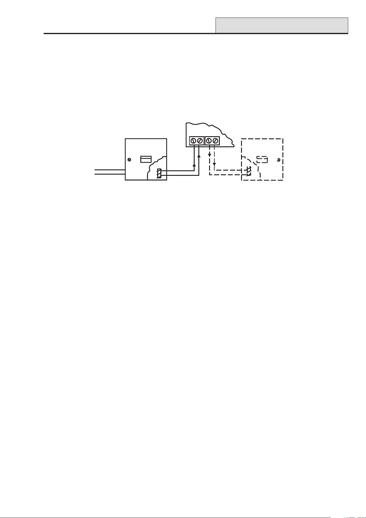
Connecting the Galaxy 2 Series to the PSTN
The Telecommunications Network Voltage (TNV) port (terminals A and B on TB1) must be permanently
connected (hard-wired) to the PSTN via a BT master socket, refer to Figure 3.
Note: If the BT master socket is the newer type (NTE5/CTE5), then the connection can be carried out by the
installation engineer. If the BT master socket is not an NTE5/CTE5, then the network operator must make the
connection.
Galaxy 2 Series PCB
Incoming
PSTN
Line
BT Master socket (
NTE5/CTE5
2
5
A B
).
PHONE
BT Master socket (
TB5
2
5
NTE5/CTE5
).
Figure 3. Connecting the Galaxy 2 Series to the PSTN
NOTES: 1. Terminals 2 and 5 on the BT Master Socket must be hard-wired to the A and B terminals
(TB1)on the Galaxy 2 Series PCB. The connection is polarity independent.
2. It is strongly recommended that the Galaxy 2 Series panel is the only device on the line.
3. If another device is to be connected to the line, connect the PHONE terminals on the PCB
to terminals 2 and 5 on a second BT Master Socket and connect the additional devices to
the second socket.
Using cable suitable for connection to 2.8 mm diameter screw terminals, strip back approximately 20 mm of
the outer sheath and then remove approximately 4 mm of the insulation from the wires to be connected to the
Galaxy 2 Series.
Connect terminals 2 and 5 on the BT Master socket across the A and B terminals (TB1) on the Galaxy 2
Series, see Figure 3.
Private Branch Exchange (PBX) Approval
The Galaxy 2 Series may be used with some analogue PBX exchanges. The correct operation of the Galaxy
2 Series cannot be guaranteed under all possible conditions of connection to compatible PBXs.
9
Page 18

System Wiring (cont’d)
Galaxy 2 Series Installation Manual
REN and SEN Numbers
It is possible to simultaneously connect a number of items to one line of the PSTN. The limit is determined by
summing the Ringer Equivalence Number (REN) shown on each item of apparatus, ensuring that the sum of
RENs is not more than four.
The REN of the Galaxy 2 Series is one (1).
Assume that all British Telecom equipment has a REN of one unless otherwise marked.
More than one item of series apparatus may be connected to the Galaxy 2 Series ports marked phone. This is
limited by summing the Series Equivalence Number (SEN) shown on each item of series connected apparatus,
ensuring that the sum of the SENs is not more than one (1). The total series resistance, including cabling, must
not exceed 50 Ohms.
• The SEN of the Galaxy 2 Series is 0.3.
• Nominal series resistance is 90 milli-ohms.
• Nominal insertion loss is 0.1 dB.
It is recommended that the PSTN should have the following facilities:
• Outgoing calls only (when used as dialler only).
• Direct exchange.
• Tone dialling.
10
Page 19
Galaxy 2 Series Installation Manual
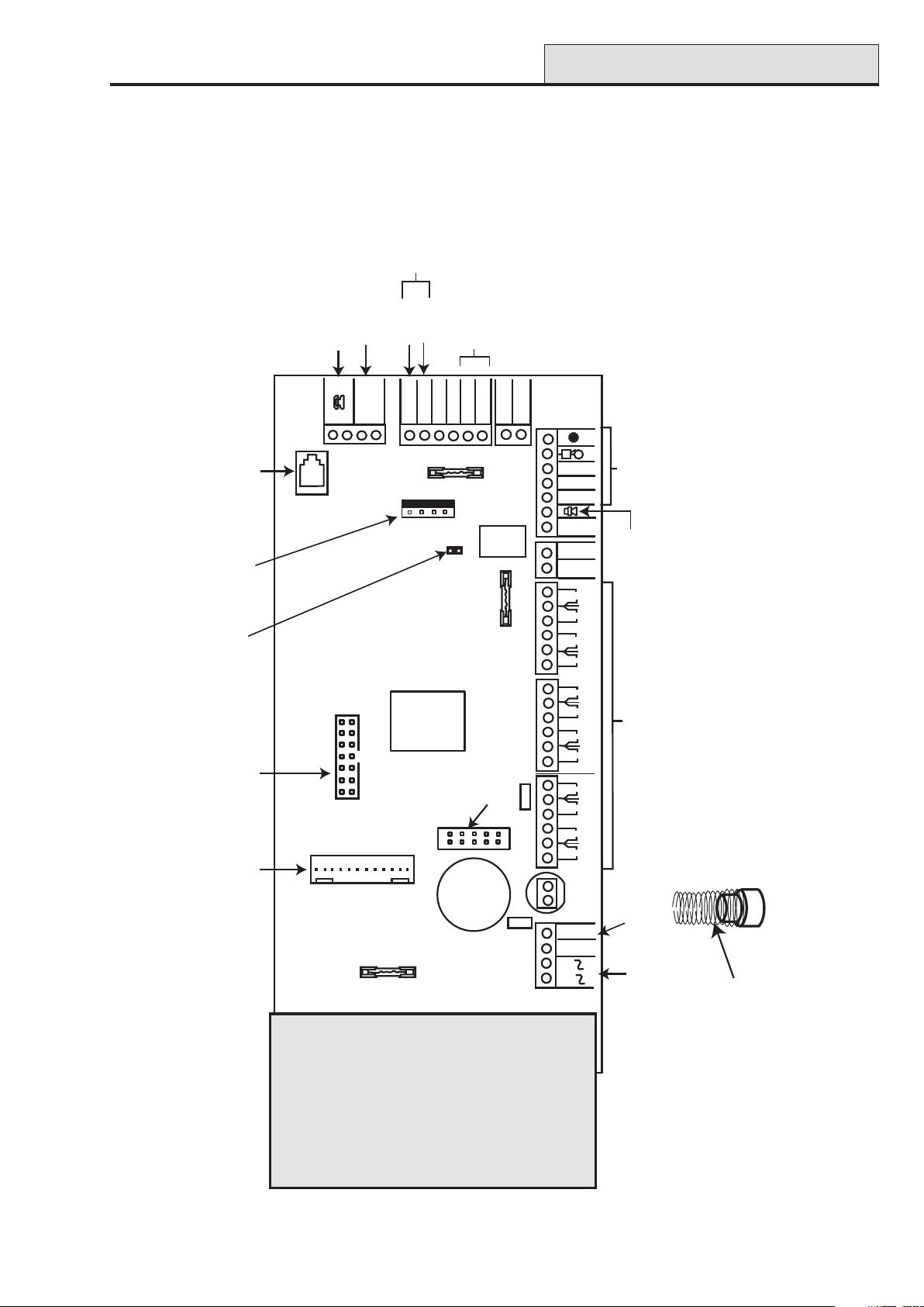
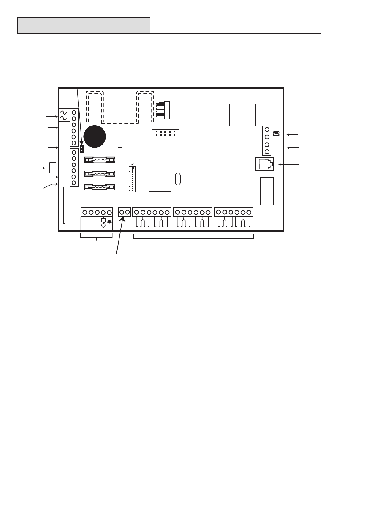
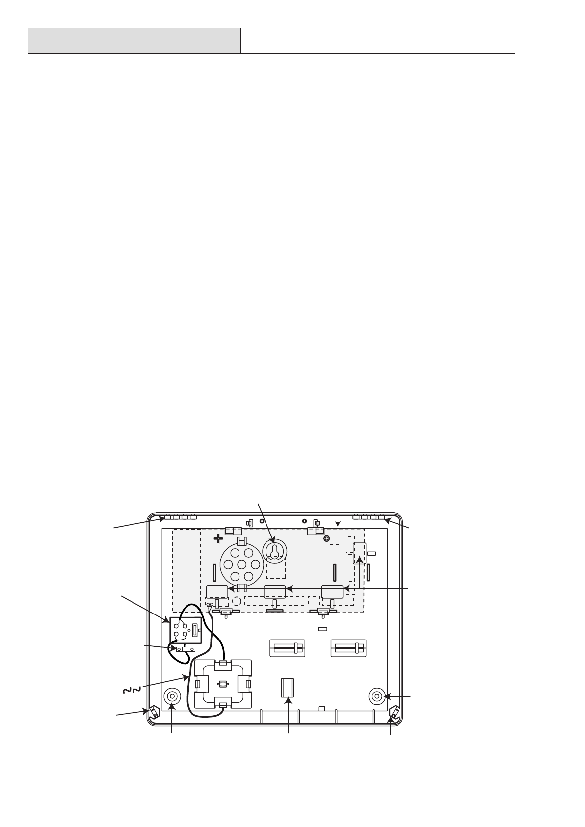
SECTION 5: HARDWARE
PCB Layout (2–44+)
For ECP
peripherals
PCB Layout
Alternative
Phone
Socket
Engineer
Header
2-way header
RS485 termination
Audio
Connector
Extension
Phone Line
Phone Output
B
A
B
LINE IN
Input
A
Data in
Data out
DO
DI
Processor
RS 485 peripherals
A
AUX+
AUX-
AUX FUSE
F2
LK1
B
F3
Program
Output
12V Aux
AUX+
AUX+
see Note
RELAY
BELL FUSE
Telecoms
Header
LED 1
T
0v
BELL
TRIG
N/O
COM
+12v
N/C
12
11
10
9
8
7
6
5
4
3
2
1
0v
0v
RIO 1
0v
0v
0v
RIO 0
0v
SAB
Connections
Loudspeaker
Note: If Relay is fitted the TRIG terminal
Zone Terminals
is used as N/C for Relay.
If Relay is not fitted the COM & N/O terminals
are not fitted. The TRIG N/C terminal is
the transistorised output.
Note: Switch SW1 and the
tamper spring are for the
plastic box only.
The metal box has a 2-way
terminal for connection to
the lid tamper microswitch.
Trigger
Header
TAMPER
LED2
BATTERY FUSE
BATT
-
BATT
+
F1
HEATSINK
Figure 4. Galaxy 2–44+ PCB Layout
11
Battery
Terminals
AC power
Tamper Spring
and switch SW1
(plastic box only)
Page 20
PCB Layout (cont’d)
PCB Layout (2–20)
2-way header
RS485 termination
AC Power
Input
Battery
Terminals
12 Volt
Auxilliary
Output
RS 485
lines
Loudspeaker
Negative
Trigger
Output
BATT +
BATT -
-
-
AUX
+
A
B
LS
TRIG
(N/C)
+
F1 (1 amp)
F2 (0.5 amp)
F3 (0.5 amp)
BATT
AUX
BELL
Power
LED
Trigger
Header
Galaxy 2 Series Installation Manual
PROG HEADER
B
A
B
LINE IN
A
X1
Extension
Phone
Output
Phone
Line
Input
Alternate
Phone
Socket
COM N/O BELL
+12v
Connections
0V T
SAB
6
2
1
3
5
4
7
Zone Terminals
2-way
connector
Note: Switch SW1 and the
tamper spring are for the
plastic box only.
The metal box has a 2-way
terminal for connection to
the lid tamper microswitch.
Note: If Relay is fitted the TRIG terminal
is used as N/C for Relay.
If Relay is not fitted the COM & N/O terminals
are not fitted. The TRIG N/C terminal is
the transistorised output.
Figure 5. Galaxy 2–20 PCB Layout
10
9
8
12
11
12
Page 21
Galaxy 2 Series Installation Manual
1K
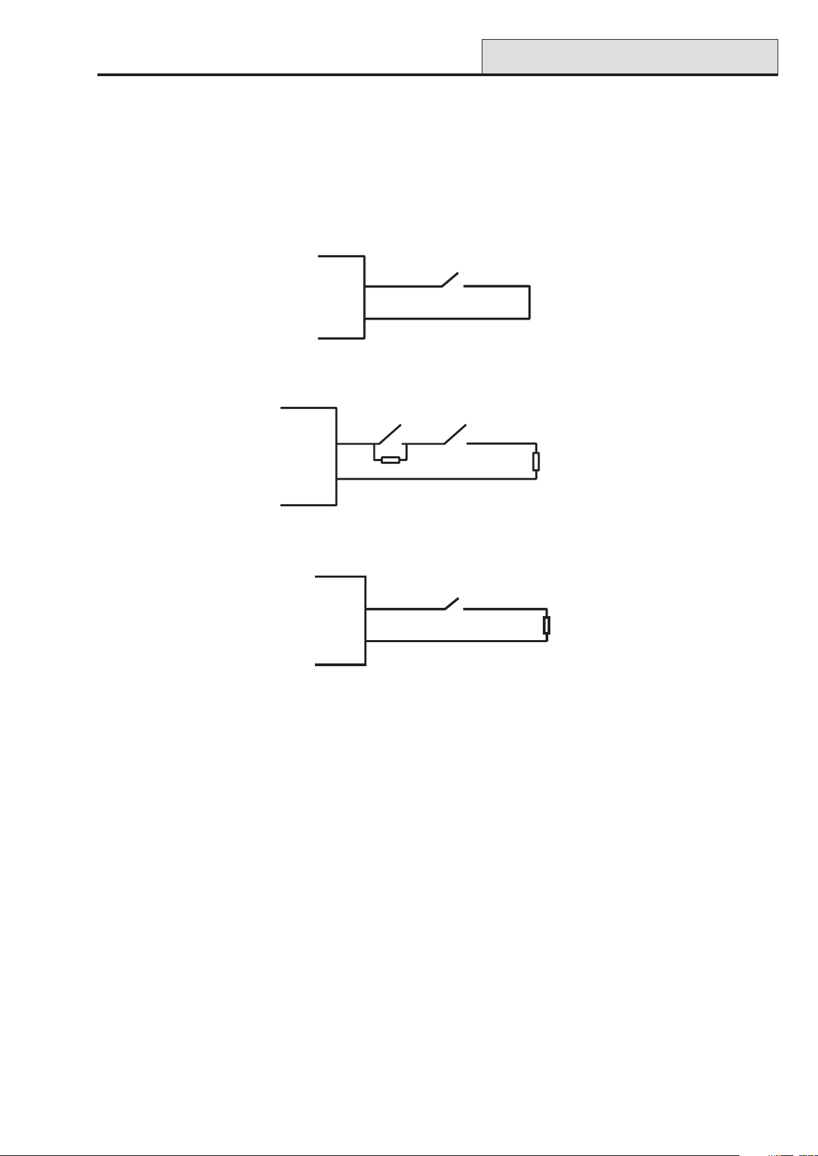
Zones
Zones
The Galaxy 2–20 has 12 on-board zones expandable to 20 (RS485 bus).
The Galaxy 2–44+ has 12 on-board zones expandable to 44 (RS485 bus) or 36 (ECP bus).
The zones on the Galaxy 2 Series can function in one of three modes; Normal Closed, Double Balanced and
U.S. End of line. Zone wiring for the three modes are illustrated in the following three Figures:
Figure 6. Zone wiring for Normal Closed Zones
ALARM TAMP
1K
1K
Figure 7. Zone wiring for Double Balanced Zones
1K
Figure 8. Zone wiring for US EOL Zones
The mode of operation for the zones is programmed from menu option 51.46 = Parameters. Zone Resistance. The default zone resistors are 1k ohm. However this can be changed in option 51.46. It is strongly
recommended that the maximum cable run on each zone is 100 m.
Zone Links
The bell tamper circuit can be shorted using the Links provided in the installation kit. If the zones are programmed as Double Balanced or U.S. End of Line, fit a 1k resistor across the zone and not the zone link. It is
strongly recommended that this be done if any of the circuits are not to be used.
13
Page 22
Wiring Zones
Galaxy 2 Series Installation Manual
Wiring Zones
The zones on Galaxy 2 Series panels are defaulted as double balanced. Each zone is 1 kΩ closed and 2 kΩ
open. The transition from 1 to 2 kΩ generates an alarm condition. Refer to Table 2 for details of the zone
resistance and resulting conditions.
NOTE: The circuit debounce time (the period the zone must remain open to register a change in condition) is
300 milliseconds by default.
Zone Resistance (ohms) Condition
0-700 Tamper Short Circuit (TAMP S/C)
700-1500 Normal (CLOSED)
1500-11000 Alarm (Open) (OPEN)
11000-infinity Tamper Open Circuit (TAMP O/C)
Table 2. Zone Resistance
Multiple detectors can be wired into a single zone. The maximum number of detectors that can be connected
to a single zone is 10.
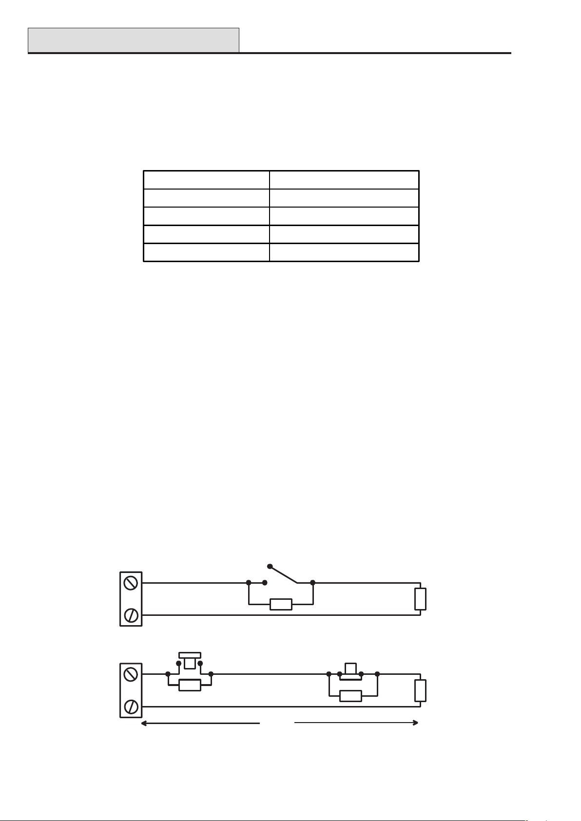
Wiring Keyswitches
The transition from 1 kΩ to 2 kΩ initiates the setting procedure of an unset system, the transition from 2 kΩ to
1 kΩ instantly unsets a set system. If the system is already set, then the transition from 1 kΩ to 2 kΩ has no
effect. If the system is unset, the transition from 2 kΩ to 1 kΩ has no effect.
The wiring of the keyswitch is shown in Figure 9.
Wiring Push-Set Buttons
Zones programmed as Push-Set (terminator) buttons can be open going closed (2 kΩ to 1 kΩ) or closed
going open (1 kΩ to 2 kΩ). The first activation of the terminator button initialises its status to the system.
NOTE: For push-set zones to operate, parameter 51.08, Exit Terminate, must be set up.
The wiring of the terminator is shown in the following Figure .
1k to unset, 2k to set
(only for a * keyswitch zone)
Keyswitch
zone
1k
1%
1k
1%
Push-set
zone
Open - Closed
1k
1%
OR
100m
Closed - Open
1%
1k
Figure 9. Keyswitch/Push-Set Zone wiring
14
1k
1%
Page 23
Galaxy 2 Series Installation Manual
Zone Addresses
Zone Addresses
Each zone on the Galaxy 2 Series has a 4-digit address. For example: 1004, 1058. The address is made up of
three reference numbers as shown in the following figure:
Example: 1004
1
00 4
Represents Panel
Line No.
GALAXY
2 Series
PANEL
1
Represents
RIO Address
RIO
ADDRESS 00
Represents
Zone No. 1-8 on
RIO/Expander
ZONE 4
Figure 10. Zone Addresses
The example above, 1004, is the detector connected to line 1, RIO 00, zone 4.
Zone Numbering System
The numbering system is as follows:
1. The first number is the Galaxy 2 Series Panel line that the RIO/Expander is connected to. This will
always be 1.
2. The next two numbers refer to the address of the RIO/Expander that the zone is on.
00 = On board RIO
01 = On board RIO
02 = RIO/Expander 1
03 = RIO/Expander 2
04 = RIO/Expander 3
05 = RIO 4
3. The last number is the actual zone on the RIO/Expander 1-8. Therefore the valid zone numbers are:
1001 - 1004
1011 - 1018
1021 - 1028
1031 - 1038
1041 - 1048
1051 - 1058
This gives a total of 44 zones.
15
Page 24

Output Addresses
Galaxy 2 Series Installation Manual
Outputs
The Galaxy 2 Series has four on-board outputs; Bells, Strobe, Speaker and Set. The format of the addressing of the outputs is similar to zones. The addresses of these outputs are as follows:
Output
Address
1001 Set 100 Off 0V
1002
*
1003 Bell 100 Off 0V
1004 Strobe 100 Off 0V
*NOTE: Output 1002 - This output is configured as a 16 Ohm speaker driver (AC signal). The speaker
should be connected between this output and +12V. The speaker Entry/Exit volume is controlled
by parameter 51.10. It is possible to reprogram the output to operate as a normal switched
negative output by programming parameter 51.15 to 0=Switch DC. However, when it is
reprogrammed to operate as Switch DC, a loudspeaker should never be connected directly to
this terminal otherwise damage may result. Always ensure that this parameter is set to 1=SPK
Driver, before connecting a loudspeaker.
Default
function
SPK Driver - - -
Current (mA) Normal State Active State
Table 3. Output Addresses
Trigger Header
The Trigger Header on the Galaxy 2 Series is a set of pins, which consists of programmable outputs for an
external communication module. The connection is via an optional ribbon cable (Part No. A229).
Trig 1-8
There are eight trigger outputs, which are intended as communication triggers, but can be used for any pur-
pose. By default these outputs are programmed as positive. They are designed to sink current (to 0V) not
source current (from 12V). The addresses of these outputs are as follows:
Output
Address
0001 Fire 100
0002 Panic 100
0003 Intruder 100
0004 Set 100
0005 Omit 100
0006 Not Used 100
0007 Confirm 100
0008 Not Used 100
Default
function
Current (mA)
Table 4. Trigger Output Addresses
The function of the trigger outputs can be programmed in menu 53=Outputs.
16
Page 25
Galaxy 2 Series Installation Manual
Reset
Line Fault
GND
+12V
Trig 1
Trig 2
Trig 3
Trig 4
Trig 5
Trig 6
Trig 7
Trig 8
Trigger Header
Inputs
Line Fault: This input tells the panel that the communicator has a telephone line fault (active low).
Reset: This input from the communicator resets the panel on a low to high signal (negative removed).
Supply
A 100 mA, 12V output is also provided. The output is fused by the on-board AUX FUSE (F2).
Figure 11. Trigger Header
Data Buses
Two separate data buses are available to connect the Galaxy 2–44+ panel to its peripherals.
Communication between the Galaxy 2–44+ control panel and the peripherals attached to it (see Figure 1),
takes place on the data bus. The control panel constantly monitors the peripherals attached to it. A break in
the communication from any of the peripherals generates a tamper alarm.
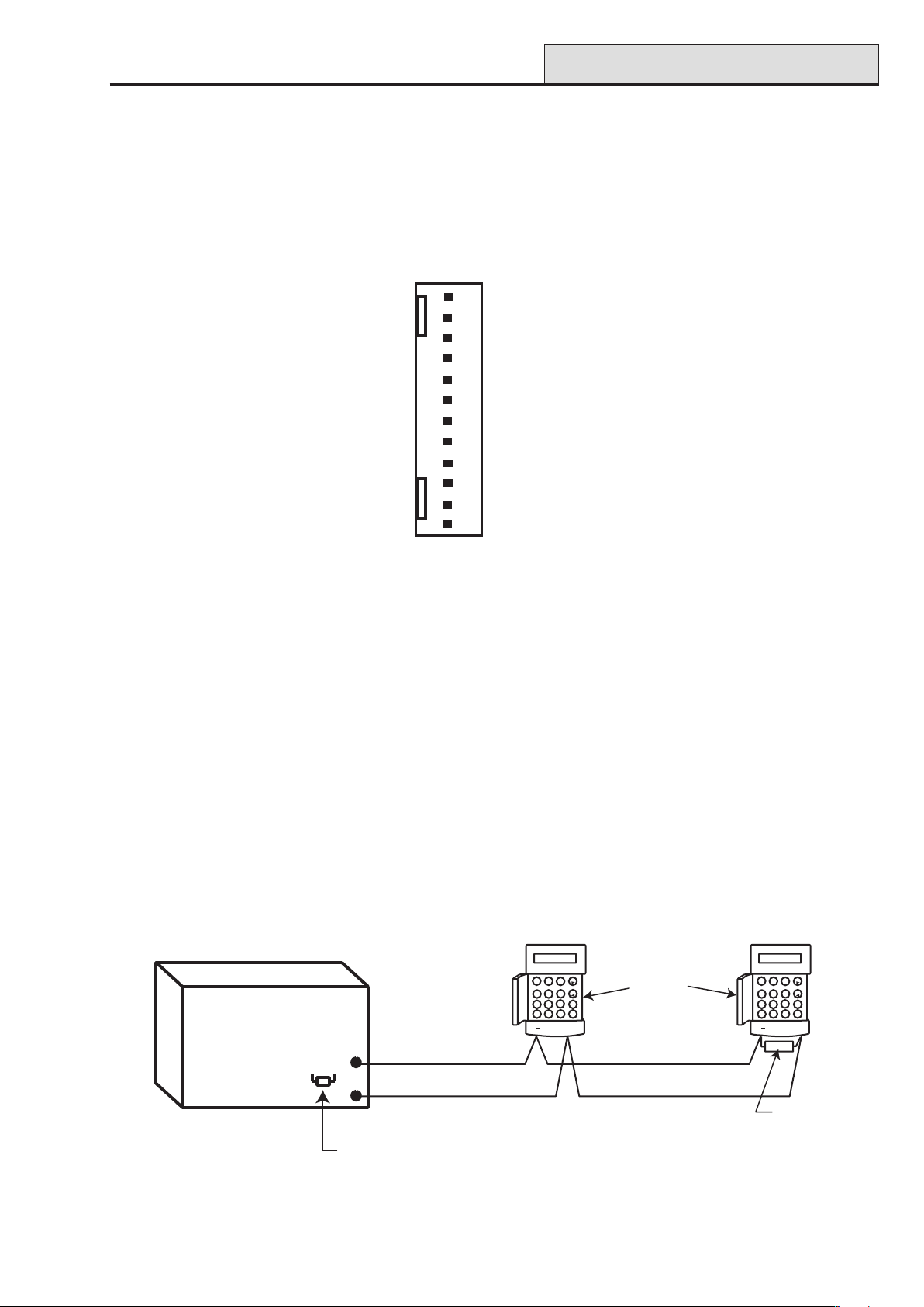
RS485 Wiring Configurations
The system must be wired in a daisy-chain configuration. That is the A line from the previous peripheral is
connected to the A terminal of the current peripheral and then on to the A line of the next peripheral.
The RS485 (AB) line must have a 680 Ω resistor fitted across the A and B terminals of the last peripheral on
the line.
Galaxy 2-44
Control Panel
680 Ω
GALAXY 44 V1.0
09:51 01/08/04
A
1
2
3
B
4
5
6
ent
9
8
7
esc
0
#
*
A
B
A
B
Factory fitted on PCB
Figure 12. Daisy-chain Configuration
17
Keypad
OR
Peripheral
A
GALAXY 44 V1.0
09:51 01/08/04
1
2
3
4
5
6
9
8
7
0
#
*
680 Ω EOL
A
B
ent
esc
B
Page 26
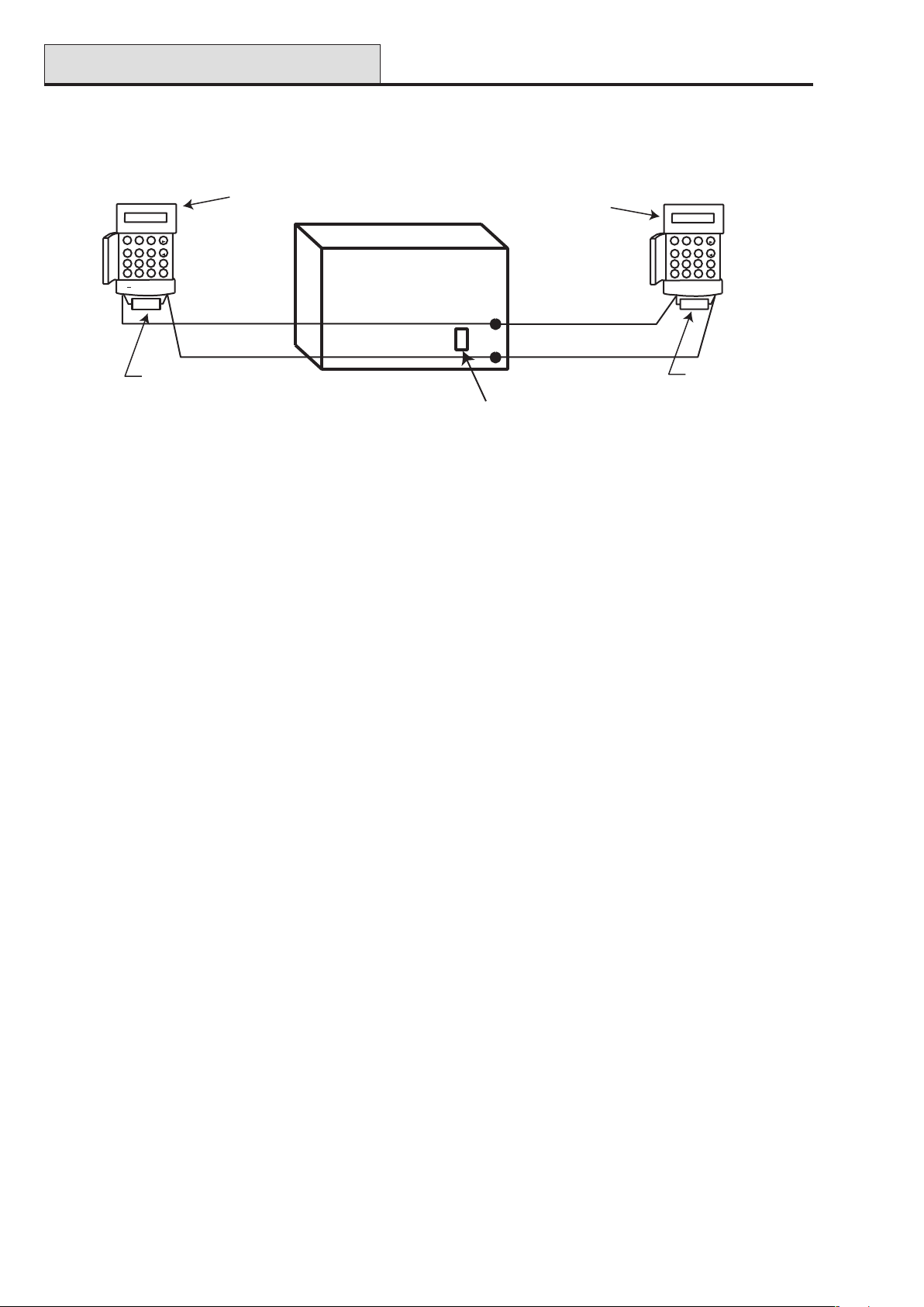
RS485 Wiring
Galaxy 2 Series Installation Manual
If two lines are connected, both ends must be terminated with 680 Ω resistors and the appropriate End OF
Line (EOL) resistor on the control panel PCB must be disconnected by removal of link LK1.
Keypad
OR
Peripheral
1
4
7
*
GALAXY 2-44 V1.0
09:51 01/08/04
2
5
8
0
A
3
B
6
ent
9
esc
#
AB
Galaxy 2-44
Control Panel
A
Keypad
OR
Peripheral
GALAXY 2-44 V1.0
09:51 01/08/04
A
1
2
3
B
4
5
6
ent
9
8
7
esc
0
#
*
A
B
B
680 Ω EOL
Remove link LK1
680 Ω EOL
Figure 13. Twin AB Line Daisy-Chain Configuration
RS485 Wiring Recommendations
1. The system must be wired in a daisy-chain configuration. Spur and star configurations must not be used.
2. The recommended cable used to connect the RS485 (AB) line is twisted pair screened cable (Belden
8723 equivalent). However, for cable runs of less than 100m in normal environments, standard 4-core
cable can normally be used.
3. There must only be a single AB pair of wires in each of the cables.
4. The power supply in the Galaxy 2 Series control panel and remote power supplies must not be connected
in parallel.
5. The 0V of all remote power supplies must be connected in common to the 0V of the Galaxy 2 Series
control panel.
6. Ensure that any extension loudspeakers are not wired in the same cable as an AB pair of wires.
7. Where possible, ensure that the AB cable is at least 30 centimetres away from any other cables.
8. Where possible, ensure that the AB cable does not run parallel to other cables for extended
distances (maximum five metres).
9. The maximum length of cable run is one kilometre.
18
Page 27
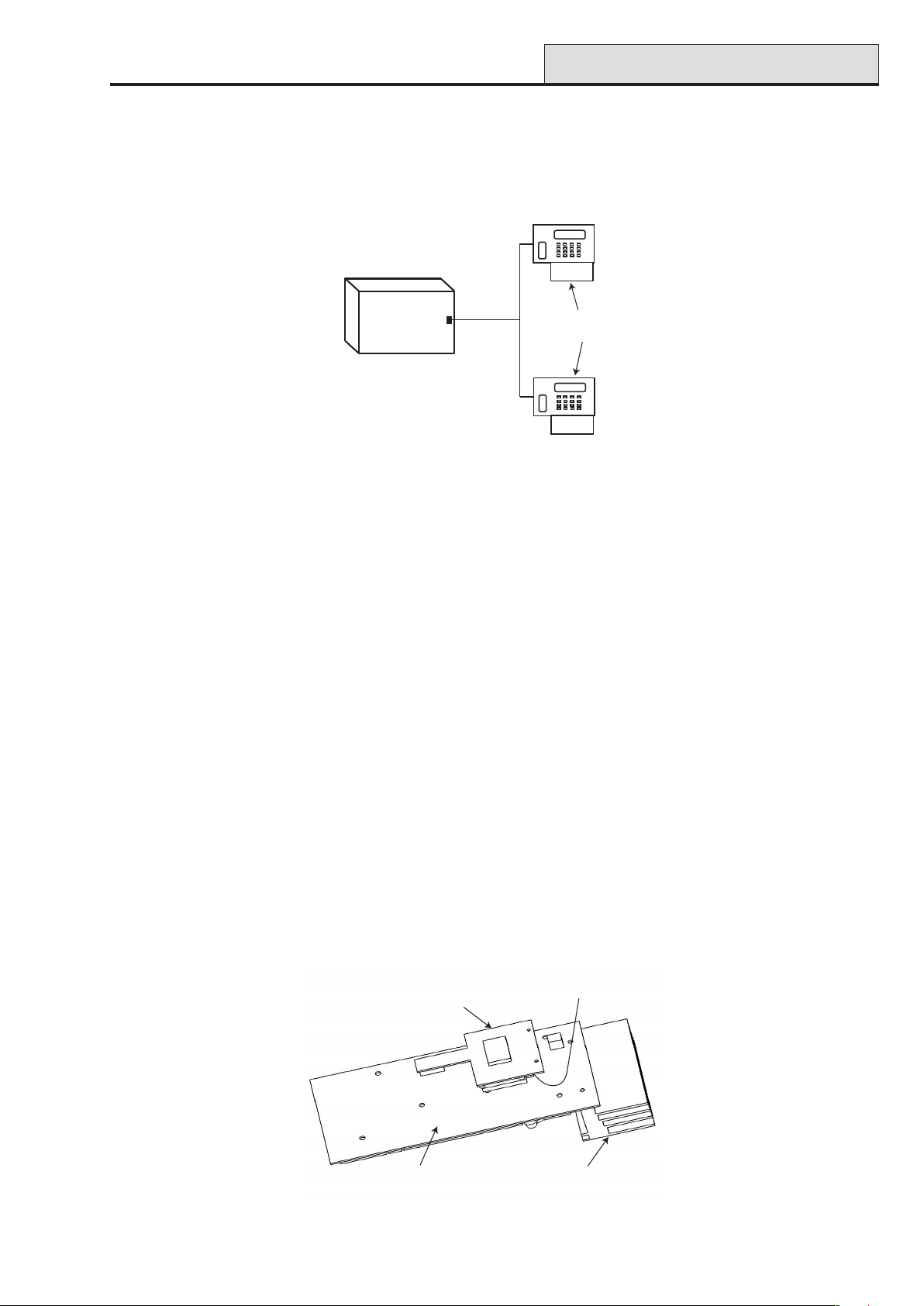
Galaxy 2 Series Installation Manual
ECP Bus
ECP Bus (2–44+ Only)
The ECP bus can operate at the same time as the RS485 bus. The cable can be standard 4-core and can be
spurred or T wired.
The maximum length of cable run is 100 metres.
Galaxy 2-44
Control Panel
ECP Bus
Keypad
OR
Peripheral
Figure 14. ECP Line - T Wire Configuration
Built-in Dialler/Modem
The built-in dialler allows signalling to an Alarm Receiving Centre (ARC), SMS signalling and remote servicing
from a PC.
LED’S
There are two LED’s on the Galaxy 2–44+ PCB. Pulsing of the red LED1 indicates an active telecommunications. Illumination of the green LED2 indicates the presence of AC mains supply.
There is one LED on the Galaxy 2–20 PCB. Pulsing of this LED indicates an active telecommunications.
Audio Header (2–44+ Only)
This is a 14-way shrouded header for audio connection. When an alarm is received at the ARC, the ARC can
communicate through a loudspeaker at the premises, and ask for a password before authenticating the alarm.
GSM Interface (2–44+ Only)
This module provides a mobile telecommunications interface to provide an alternative to the land line. The
GSM interface provides the same functionality as the built-in dialler/modem. The module attaches to the
underside of the PCB and also connects to the antenna on the edge of the enclosure box.
to antenna on
enclosure box
Heatsink
Galaxy
2-44 PCB
(underside)
GSM
Module
Figure 15. GSM Module fitted to underside of Galaxy 2-44 PCB
19
Page 28
Panel Mounting
Galaxy 2 Series Installation Manual
Panel Mounting (Plastic Box)
Installation Kit
The Galaxy 2 Series plastic box comes with an installation kit. It contains 13 zone links, a cable clamp with
two self tapping screws, two M4 x 20mm lid screws, a tamper spring, battery connector leads and 24, 1K
resistors.
WARNING: The lid of the plastic box must not be removed before isolating the mains supply.
Illumination of the keypad power LED indicates the presence of a.c. mains supply.
Removing the Enclosure Lid
1. Remove the two M4 x 20 mm pan head screws from the bottom corner of the lid.
2. Pull the lid away from the lid hinge recesses (two menus of four) on the top of the enclosure base .
3. Remove the lid.
Installing the Enclosure Lid
1. Hold the lid at an angle of 90 deg. to the enclosure base.
2. Place the eight (two menus of four) lid hinges into the recesses on the top of the enclosure base.
3. Swing the lid down making sure that the hinges fit into the holes in the top of the enclosure rim.
4. Attach the lid in place with the two M4 x 20 mm pan head screws provided.
Removing and Replacing the Galaxy 2 Series PCB
NOTE: The plastic box comes with the PCB installed. The PCB must be removed to enable access to the
keyhole mounting slot (see Figure 16).
Lid Hinge
Recess
Mains Terminal Block
with 200mA fuse
Secure Mains
Cable After Feeding
Through Entry Point
Keyhole
Mounting
Slot
PCB Clip
PCB
Lid Hinge
Recess
Keyhole
Mounting
Slot
Cable Entry
Points
PCB Clip
Transformer Output
Lead to PCB
Terminal Marked
Lid Screw
Mounting
Hole
User Instruction
retaining Clip
Figure 16. Galaxy 2 Series Plastic Box Layout
20
Mounting
Hole
Lid Screw
Page 29

Galaxy 2 Series Installation Manual
Panel Mounting (cont’d)
Remove the PCB
1. Gently pull back the PCB mounting clips to free the PCB.
2. Lift the PCB free of the PCB mounting pillars.
Replace the PCB
1. Insert the PCB into the PCB mounting slots.
2. Ensure that any cabling is clear of the PCB support pillars.
3. Gently pull back the PCB mounting clips and place the PCB on top of the PCB support pillars.
4. Release the PCB mouting clips ensuring that they spring back into place and that the PCB is held firmly in
place.
Mounting the Plastic Enclosure Base
Use the keyhole slot in the plastic box base to position the base. Three mounting screws (not provided) are
required to mount the plastic box. Fix one of the screws into the mounting surface, this will be used for the
top, keyhole mounting hole. Hang the enclosure base onto the mounting screw ensuring that the screw sits in
the narrow portion of the keyhole.
All cables must be brought into the enclosure base via the cable entry points shown in Figure 16. There are six
cable entry holes for the entry of alarm cables. There is one a.c. mains cable entry point located below the
mains terminal block.
Fitting the Tamper Spring
The Galaxy 2 Series plastic box enclosure is supplied without the tamper spring in place. The panel will not
function without a Tamper. It is therefore the engineer’s responsibility to correctly attach the tamper spring.
The spring is supplied in the Installation Kit. The engineer must ensure the spring is securely attached to the
Tamper Post (SW1). Refer to Figure 4.
21
Page 30
Panel Mounting (cont’d)
Galaxy 2 Series Installation Manual
Panel Mounting (Metal Box)
Installation Kit
The Galaxy 2 Series metal box comes with an installation kit. It contains two No.8 x 12 mm self-tapping lid
screws, 6160 Text Programming Overlay, two battery leads (one red and one black), 10 mm cable staple and
24, 1K resistors.
WARNING: The lid of the metal box must not be removed before isolating the mains supply.
Illumination of the keypad power LED indicated the presence of a.c. mains supply.
Removing and Installing the Enclosure Lid
1. Remove the two self-tapping screws that secures the lid to the enclosure base.
2. Slide the lid forward on the locating slots then lift clear.
3. To install the lid, simply reverse the process.
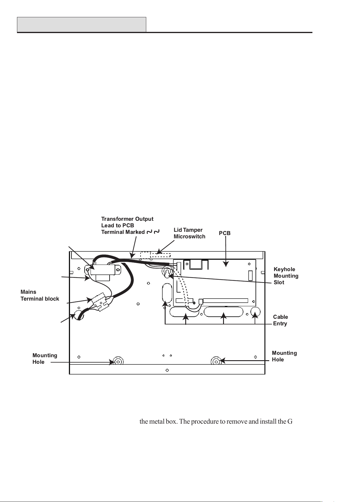
NOTE: The top self-tapping screw activates the Lid Tamper Microswitch.
Transformer
Enclosure
Earth
Connection
Mains
Terminal block
with 200mA Fuse
Mains Cable
Entry Hole
Lid Tamper
Microswitch
Figure 17. Galaxy 2-20 Series Metal Box Layout
NOTE: Figure 17 shows the Galaxy 2-20 in the metal box. The procedure to remove and install the Galaxy
2-44+ is identical to the 2-20.
22
Page 31

Galaxy 2 Series Installation Manual
Panel Mounting (cont’d)
Removing and Replacing the Galaxy 2 Series PCB
NOTE: The metal box comes with the PCB installed. The PCB does not have to be removed to enable
access to the keyhole mounting slot (see Figure 17).
Mounting the Metal Enclosure Base
Use the keyhole slot in the metal box to position the base. Three mounting screws (not provided) are required
to mount the metal base. Fix one of the screws into the mounting surface, this will be used for the top, keyhole
mounting hole. Hang the enclosure base onto the mounting screw ensuring that the screw sits in the narrow
portion of the keyhole.
All cables must be brought into the enclosure base via the cable entry points shown in Figure 17. There are
four cable entry holes for the entry of alarm cables. There is one a.c. mains cable entry point located below
the mains terminal block.
NOTE: There are three knockouts at the top of the metal enclosure base and three at the bottom for cable
entry if required.
23
Page 32

Peripherals
Galaxy 2 Series Installation Manual
Peripherals - Installation, Wiring & Addressing
Configuring
New peripherals will be configured onto the system at system power up or on learning programming mode.
Changes to peripheral addresses will only take effect when the peripheral is re-powered.
General
The following peripherals can be connected to the Galaxy 2 Series:
RS485 Bus: Mk7 LCD Keypad/Keyprox; RIO; PSU; RF Portal.
NOTE: Up to four keypads (including keyprox) can be fitted to this line. Keypads/keyproxes must be wired
in daisy chain configuration (see RS485 Wiring Configuration). The maximum length of cable for
all peripherals on this line is one km.
PANEL PERIPHERAL
AUX+
AUX-
A
B
+
A
B
Table 5. RS485 Peripheral Wiring
ECP Bus (2–44+ only): 6160 Keypad/Keyprox; 5800 RF receiver; ECP zone expander.
NOTE: Up to four keypads can be fitted to this line. Keypads can be wired to the control panel indepen-
dently, in series or in star configuration. The maximum cable length for all peripherals connected to
this line is 100m.
LENAP
+XUA
-XUA
OD
ID
0616
DAPYEK
+)der(+P/IV21+
-)kcalb(--
Y∇ )wolley(ODOD
G∆ )neerg(IDID
0085
REVIECER
ENOZ8+4
REDNAPXE
Table 6. ECP Peripheral Wiring
The following table identifies the peripheral addresses:
LAREHPIREPSSERDDA
xorpyek/dapyeK7kM3-0
OIR5-2
USP5-2
revieceRsseleriW5-4
dapyeK06163-0
xorpyeK06165-4
55-4
revieceRFR008
rednapxEenoZPCE4-2
Table 7. Peripheral Addresses
NOTE: No two peripherals connected can share an address, regardless of the data bus to which they are
connected.
24
Page 33

Galaxy 2 Series Installation Manual
Peripherals (cont’d)
Mk7 LCD Keypad/Keyprox
The Mk7 keypad is a 16 character alpha-numeric keypad used to program and set the Galaxy 2 Series. The
window display is spread over two lines.
The Mk7 keyprox is a standard keypad with a proximity card reader combined into one housing. This allows
dual function setting/unsetting ability from one station without the need for a separate card reader.
Keypad/Keyprox Installation
1. Remove the keypad from its packaging.
2. To attach the keypad to the wall, the back plate must first be removed from the front plate. To do this,
insert a suitable tool into both openings at the bottom of the keypad and turn the tool gently.
CAUTION: When the keypad is separated make sure that the anti-static precautions are taken
with the keypad pcb to avoid damage from esd (electro static discharge).
3. Use the backplate as a template, then mark the locations for the three attachment screws in the
required position. Use the keyhole slot at the top of the backplate and the two elongated
holes at the bottom.
cable
channel
cable
stowage
area
elongated
hole
aperture
keyhole slot
aperture
sacrificial
wall
tamper
Figure 18. Galaxy Mk7 Keypad Backplate Installation
25
knockout
hole
Page 34

Peripherals (cont’d)
4. If you are using a wall-run cable for the keypad (A, B, +, -) position the cable behind the back plate in
the cable channels provided. The cable can be run in from either the top or the bottom of the back plate.
Use a sharp tool to remove the plastic from the top or the bottom of the cable guides on the back plate
skirting.
CAUTION: Use of any screws other than No. 6 Pan-head can damage the keypad
mouldings.
5. Make sure that the keypad wiring is fed through the large opening on the keypad backplate, then
position the keypad base on the wall and attach it securely with the three No. 6 Pan-head screws.
6. If an off the wall tamper is required, using a No. 6 Pan-head screw, secure the sacrificial wall
tamper, indicated in Figure 18, to the wall. Make sure that the tamper knockout is still
connected to the backplate moulding.
7. Connect the A, B and power wires to the correct terminals of the removable, four-way connector
block.
Galaxy 2 Series Installation Manual
Mk7 Keypad/Keyprox Addressing
The valid keypad/keyprox addresses are: 0, 1, 2, and 3. A 16-way Rotary Address Switch is used to address the Keypad/keyprox. The address switch assigns a hexadecimal address value to the keypad/keyprox.
NOTE: Any change to the keypad address must be made when the power is disconnected from the keypad.
Adding a Mk7 Keypad/Keyprox to the System
When adding a keypad to an existing system, the following points must be considered:
1. Ensure that the keypad to be added has a unique address from the other keypads on the system.
2. Ensure that the keypad has a valid address.
3. Connect the keypad to the system - refer to the Keypad Installation Procedure.
4. Access engineer mode.
5. Connect the RS485 (AB) line of the keypad in parallel with the RS485 (AB) line of the
existing keypads.
6. Connect + and – terminals of the keypad to a power supply.
7. Exit engineer mode - engineer code + esc.
8. The Mk7 keypad displays the message 1 MOD. ADDED — esc=CONTINUE. Press the esc
key; the keypad returns to the unset banner. If this message is not displayed, the keypad is not
communicating with the control panel and has not been configured into the system.
9. The keypad is now configured into the system.
26
Page 35

Galaxy 2 Series Installation Manual
RIO
Remote Input Output (RIO)
Galaxy RIO’s can be added to the RS485 Bus on the Galaxy 2 Series control panel. Each additional RIO
expands the system by eight zones and four outputs.
3k3Ω pull-up
resistors
Tamper
Switch
SW2
Addressing the RIO
Outputs
1
R3
R1
1
RS 485
R7
Zones
5
BA
IC2
6
23
LK1
2
4
SW4
3
R5
LED
4
Figure 19. Galaxy RIO
Power
-
+
IC1
78
-
LK4
LK3
LK2
+
E/E
S
SLAVE
SW1
IC4
IC3
Rotary
Address
Switch
Rev 0.3
The Galaxy RIO must be given a unique address before it is connected to a power supply (see Table 8. RIO
Addresses).The address is selected using the 16-way Rotary Address Switch (SW1).
sserddAdetacollAsenoZ
28201-12014201-1201
38301-13014301-1301
48401-14014401-1401
58501-15014501-1
501
stuptuO
detacollA
Table 8. RIO Addresses
Connecting the RIO
The RS485 (AB) line of the Galaxy RIO must be wired in parallel (daisy-chain configuration) with the RS485
(AB) line of any keypads connected to the system. The RIO requires 12 Vd.c. (range 10.5 to 16.0 V) and
40 mA. This can be supplied from the control panel power supply or from a remote power supply if the
distance causes a large voltage drop on the cable.
NOTE: A 3 Ampere Smart PSU can be fitted in place of a RIO.
27
Page 36

RIO (cont’d)
Galaxy 2 Series Installation Manual
Configuring the RIO
The added RIO is configured into the system on exiting from engineer mode. If the message XX Mod Added
[<],[>] To View is displayed, the system has recognised that a new module is present. Press the A or B keys
to confirm that the RIO has been added. If this message is not displayed or the RIO is not on the list of added
modules, then the RIO is not communicating with the control panel or has been set to the same address as the
RIO already connected to the system.
The flash rate of the red LED (LED1) on the RIO indicates the status of the communication with the control
panel - refer to the following Table:
etaRhsalFgninaeM
FFO9.0/NO1.0snoitacinummoclamroN
FFOylppus.c.doN
OIR
FFO5.1/NO5.1metsysotniderugifnocneebtonsah
FFO2.0/NO2.0metsyshtiwnoitacinummoctsolsahOIR
FFO1.0/NO9.0snoitacinummocroopyreV
Table 9. RIO LED Flash Rates
Zones
The Galaxy RIO has eight programmable zones. These default to INTRUDER. Each zone is Double
Balance monitored with a 1 kΩ resistor in series with the zone detector and a 1 kΩ (1%) resistor in parallel
across the detector switch. The change to 2 kΩ (1%) resistance registers the zone as open/alarm.
Outputs
The RIO has four transistorised outputs. Each output is connected to +12 V via a 3k3Ω pull-up resistor
(refer to Table 10). When an output is activated, the load is switched to the negative supply voltage (ground
or 0 V) of the RIO. The current available through each output is 400 mA.
The default functions and pull-up resistors of each RIO output, when connected to a Galaxy 2 Series are
shown in the following Table:
Output No. Function Pull-up Resistor
1 Not Used R1
2 Not Used R3
3 Not Used R5
4 Not Used R7
Table 10. RIO Output Default Functions
Link LK1 on the RIO, if altered when the module is powered down, modifies the RIO operation:
• LK1 - short circuit this to by-pass the RIO lid tamper switch SW2
28
Page 37

Galaxy 2 Series Installation Manual
PSU
Power Supply Unit
The Galaxy 2 Series Power Supply Unit (PSU) is available in two variants.
The Galaxy Power Unit is a 3-ampere power supply. The Galaxy Power RIO is a Power Unit plus an on-
board Remote Input Output (RIO) module. Both variants are configured in the same way.
Off-wall
Tamper
OW
LID
TAMP
Bell-Box
connection
Comms
Line
Outputs
+14.5
0V
+12V2
+12V1
A(DO)
B(DI)
OP4
OP3
OP2
OP1
TAMP
LK5
F1
F4
0V
F3
0V
LK4
LK3
LK2
LK1
3
1 1/2 2
HEATSINK
LK10
F2
Control Unit
5/6
3/4
5
6
4
Zones 1-8
7
13.8
From
0V
14.5
Powe r
0V
BT
LED2
AC/F
Rotary
Address
Switch
SLAVE
E/E
+BAT
-BAT
Block
To Control
Unit
Powe r
Header
13.8V
0V
14.5V
0V
BT
AC/F
Power Block
NEUTRAL
LIVE
WARNING: The Power Block PCB
is connected to mains voltage. Always
disconnect mains supply for at least
1 minute before removing the box lid.
Mains
Terminal
Block
(AC)
LED1
(comms)
BAT
AC
PWR
0V
FAULT OP
8
7/8
Figure 20. Power Supply Unit
Configuration
The Galaxy Power Supply Unit (PSU) consists of two modules, the Power Block and the Control Unit. The
PSU can be connected to the Galaxy 2 Series control panel via the RS485 (AB) line. The PSU can be used in
place of a standard RIO to overcome power problems that arise when the additional RIO is fitted distant to
the control panel.
A 6-way jumper lead connects the Power Block to the Control Unit.
The PSU (Power RIO variant) has eight zones and four outputs. Each variant of the PSU takes one of the
four RIO address (2 - 5). Addressing is identical to that described for RIO Modules.
The four outputs are switched 0V (0V active). Without the jumper links (LK1-4) fitted, the outputs will float in
the OFF state. They can apply a +12V signal, if required, by fitting the appropriate pull-up jumper supplied.
LK5 will short out the off-wall tamper if it is not used.
The SLAVE and E/E links must be in place for normal operation.
FAULT OP AC: This is an open collector transistor which is normally off. The output is activated by an AC
failure.
FAULT OP BAT:This is an open collector transistor which is normally off. The output is activated by a
Battery Low or Battery Fail condition.
FAULT OP POWER: This is an open collector transistor which is normally off. The output is activated by
low voltage present in +12V1 or +12V2 .
29
Page 38

PSU (cont’d)
Galaxy 2 Series Installation Manual
Installation Instructions
The installation and wiring must be performed by a competent engineer. The Galaxy Power Supply Unit must
be connected to the a.c. mains supply (230/240 Va.c. 50Hz) via a fused connection outlet. The fuse in the
mains outlet must not exceed 3A.
The Galaxy Power Supply Unit comes installed in the metal enclosure base. The installation procedure of the
panel base is as follows:
1. Route the mains cable through the hole on the right hand side of the enclosure base. Securely anchor
the cable to the box using the tie-wrap as shown in the following Figure:
Enclosure
base
Lid Tamper
Microswitch
6-w
ay jum
from
to control unit
pow
per lead
Control
Unit
Attaching hole
er block
Figure 21. Enclosure Base
Keyhole
slot (top)
Power
Block
Off-Wall
Tamper
Micro-switch
Terminal
block
Mains cable
Tie wrap
Attaching hole
2. Secure the panel base to the wall using three 1.5" No. 8 round head steel screws through the holes
provided.
The mains cable used must be a three core type (with green/yellow earth insulation) of adequate current
carrying capacity.
NOTE: The mains cable must satisfy the requirements stated in BS6500.
3. Connect the mains cable to the mains terminal block as follows:
• blue wire to the terminal marked N (Neutral)
• green/yellow wire to the terminal marked (Earth)
• brown wire to the terminal marked L (Live)
NOTE: No other connections to the mains connector are permitted.
All wiring must be in accordance with the latest edition of the IEE Wiring Regulations, BS7671 (Requirements
for Electrical Installations).
4. Power up by applying mains first. This unit can be powered up from the battery by momentarily shorting
LK10. Never leave LK10 connected, as deep discharge of the battery will occur. LK10 is for start-up
only.
30
Page 39

Galaxy 2 Series Installation Manual
PSU (cont’d)
Battery
The minimum capacity battery to supply the PSU is 1x 7Ah. The maximum capacity battery to supply the
PSU is 2 x 17Ah.
Battery Test
A battery test on full load is automatically performed once an hour and during the Engineer Mode exiting
procedure. If the battery voltage falls to 10 V while the Power Supply Unit is running on the battery, then it is
automatically disconnected to prevent deep discharge of the battery.
Specifications
Electrical (based on 34 Ah battery and UK grade 2 compliance)
Input voltage: 230V a.c. (+10%/-15%) @50Hz
Output voltage (nominal): 13.8V & 14.5V
Output current (max): 3.0A
Operating temperature: -10 deg C to +40 deg C
Aux1 & Aux2
Output voltage (nominal): 13.8V
Output current (max): 0.75A each
14.5V Output (not for EN50131: grade 2 use)
Output voltage (nominal): 14.5V
Output current (max): 0.15A (when using this current, the AUX1 & AUX2 currents will
be reduced by an equivalent amount).
Battery charge current (max): 1.4A
Maximum ripple voltage: less than 100mV
Fuses
F1 (14.5V) 500mA - 20mm anti-surge
F2 (Battery) 1.6A - 20mm anti-surge
F3 ( 12V Aux1) 1.0A - 20mm anti-surge
F4 (12V Aux2) 1.0A - 20mm anti-surge
EN50131 Compliance
This product is suitable for use in systems designed to comply with EN50131-1:2004/PD6662:2004.
Security Grade - 2
Environmental Class - II
Power Supply Type - A
31
Page 40

ECP Zone Expander
Galaxy 2 Series Installation Manual
ECP Zone Expander (2–44+ Only)
This is an expander for use on panels that use the ECP communication Bus. Up to three zone expanders can
be fitted to the Galaxy 2–44+ panel. Each expander gives 8 extra hardwired zones and four programmable
outputs. An alternative expander gives four extra hardwired zones and no outputs.
12V Pull-up
Jumpers
Tamper
Switch
Tamper
By-pass
Switch
SW 1
Outputs
2
1
34
(not fitted in 4-zone version)
Figure 22. Zone Expander Outputs
1
Data Input/
Data Output
A
B
DI
DO
Engineer
Socket
2
3
12V
12V
Input
-
+12V
I/P
4
Zone Terminals
(zones 5-8 not fitted in 4-zone version)
Output
-
+12V
O/P
Data LED
6
5
S
LK8
LK9
ZD1-0130
8
7
Address
Select
Zone Expander Outputs
The four outputs are switched 0V (0V active). Without the jumper they will float in the ‘OFF’ state (see
Figure 23). They can apply a +12V signal, if required, by fitting the appropriate pull-up jumper supplied (see
Figure 24). (This is typically required for activating comms devices). All devices wired to the outputs must
have their negative terminals wired to the switched output, and their positive terminals wired to the + 12V
output.
3k3Ω
Jumper
not
required
+12 V
+12 V
+
Siren
-
Output
terminal
0 V
3k3Ω
Jumper
fitted
+12 V
0 V
Output
terminal
Input to
dialler/Redcare
Figure 23. Output without jumper Figure 24. Output with jumper
32
Page 41

Galaxy 2 Series Installation Manual
ECP Zone Expander (cont’d)
Addressing the ECP Zone Expander
Select jumper addresses before powering up the zone expander. Available addresses are 2, 3, and 4. Refer to
Table 11 for jumper settings.
8-Zone Expander 4-Zone Expander
Address LK8 LK9 Zones Allocated
2 Off Off 1021 - 1028 1021 - 1024 1021 - 1024 0
3 Off On 1031 - 1038 1031 - 1034 1031 - 1034 0
4 On Off 1041 - 1048 1041 - 1044 1041 - 1044 0
Outputs
Allocated
Zones Allocated
Outputs
Allocated
Table 11. Zone Expander Addresses
5800H RF Receiver (2–44+ Only)
The 5800H is a remote, stand-alone radio receiver. An additional standard 6160 keypad needs to be connected to the Galaxy 2–44+ control panel when using the 5800H receiver.
Installation
Always mount the receiver where the survey receiver showed the best reception. Make sure other equipment
such as panels or power supplies are not mounted immediately next to it. As a guide, try to keep other equipment at least half a meter away. Ensure that anyone fitting any other site equipment, knows not to locate
anything close by the receiver.
Wiring
The receiver comes with a five way flying lead, which should first be plugged into the RF receiver PCB. The
coloured cables are wired direct to the Galaxy 2–44+ control panel as shown in Table 6. ECP Peripheral
Wiring. The blue wire is not used and may be cut off.
All wiring must be routed into the receiver via the holes and knockouts provided. Always make sure the wiring
runs on the side of the PCB away from the antennas.
Addressing
Set all DIP switches to OFF before powering up the 5800H RF receiver, which must be addressed as either
4 or 5. Refer to Table 12 for DIP switch settings. No other settings are required on this unit.
SSERDDAHCTIWSPID
345
4NOFFOFFO
5NOFFONO
Table 12. DIP Switch Settings
33
Page 42

RF Portal
Galaxy 2 Series Installation Manual
G2 RF Portal
The G2 RF Portal is a wireless receiver for the Honeywell V2 Domonial transmitter range. The G2 RF Portal
allows the control panel to receive signals from wire-free detectors and radio keyfobs. One RF Portal will
allow the control panel to assign wire-free detectors to any or all detection zones. However, two RF Portals
can be used to increase coverage.
A maximum of two RF Portals can be connected to the RS485 (AB) line to support up to 44 zones.
LED's
RF Circuit
Area
RF
PWR
BA
-
PANEL
RS485
line
Antenna
Engineer
Header
+
Processor
Address
Setup
Jumper
Tamper
switch
Tamper
By-pass
link
Program
Header
ADDR
LK2
SW1
SW2
LK1
Figure 25. G2 RF Portal PCB
Program Header
The Program Header allows field upgrades of flash software on the processor.
Tamper By-pass Link
The Tamper By-pass Link (LK1) must be removed to allow the lid tamper to function through the operation
of switch SW2.
LED’s
The RF LED will blink upon reception of decodeable signals. If a jam condition occurs (continuous interfer-
ence), the LED will come on constantly. It will switch off again only when the jam condition clears.
The PWR LED gives power and communication status of the RF Portal (see Table 9 - RIO LED Flash
Rates for information on the meaning of the various flash rates).
Mounting the Plastic Base
Before mounting the base it is recommended that a survey is carried out to determine the suitability of the site
for RF installation. Refer to Galaxy RF Survey Kit, Operation Instructions (II1-0011).
NOTES:
• The plastic base must be mounted so that when the PCB is installed, the antenna will point vertically
(see Figure 26, Plastic Base with PCB Installed)
• The plastic base is mounted using three screws that are not provided with the installation kit.
• The plastic base must be mounted before attaching the PCB or else access to the top left-hand
mounting hole will be severely restricted.
34
Page 43

Galaxy 2 Series Installation Manual
RF Portal (cont’d)
1. Either remove one of the knockouts in the side of the plastic base or, if fitting into an electrical box,
remove the knockout in the centre of the base (see Enclosure knockout Removal Procedure, II1-
0220).
2. Fit the two plastic supports for the PCB from the underside of the plastic base.
3. Using three screws, attach the plastic base loosely to a wall or electrical mounting box.
4. Bring in the cable from the control panel through the relevant knockout hole.
5. Firmly secure the plastic base with the three mounting hole screws.
Antenna
PCB installed
in base
Mounting hole
(partially covered
when PCB installed)
Pillar (2 off)
Clip
(pointing vertically)
Side knockout (2 off)
Mounting
Hole
Knockout
(if using an
Mounting
hole
Plastic support (2 off)
Plastic Base
electrical
mounting box)
Figure 26. Plastic Base with PCB Installed
Attaching the PCB
1. Place the PCB over the two plastic supports and the two pillars.
2. Pull back the clip then press the PCB firmly into place.
3. To allow the lid tamper switch (SW2) to function, remove the by-pass link (LK1).
4. Attach the lid tamper spring over the lid tamper switch (SW2).
Addressing the RF Portal
The RF Portal must be given a unique address before it is connected to the power supply. This address is
selected via the Address Setup Jumper and can be 4 or 5.
To set the address as 4, fit the jumper to one pin only (open) of Address Setup Jumper LK2.
To set the address as 5, fit the jumper across the two pins (shorted) of Address Setup Jumper LK2.
35
Page 44

RF Portal (cont’d)
Galaxy 2 Series Installation Manual
Connecting the RF Portal
The RS485 (AB) line of the RF Portal must be wired in parallel (daisy-chain configuration) with the RS485
(AB) line of any keypads connected to the system. The RF Portal requires 12 Vd.c. (range 9.0 V to 14.0 V)
and 55 mA. This can be supplied from the control panel power supply or from a remote power supply if the
distance causes a large voltage drop on the cable.
Configuring the RF Portal
The added RF Portal is configured into the system on exiting from engineer mode. If the message XX Mod
Added [<],[>] To View is displayed, the system has recognised that a new module is present. Press the A or
B keys to confirm that the Receiver has been added. If this message is not displayed or the Receiver is not on
the list of added modules, then the Receiver is not communicating with the control panel or has been set to the
same address as the Receiver already connected to the system.
Attaching the Plastic Box Lid
Place the lid over the plastic base then firmly attach with the four self-tapping screws provided.
Specifications
Physical
PCB Width: 104.5 mm
Height: 68 mm
Weight: 42 g
PCB with antenna Width: 125 mm
Height: 76 mm
PCB in Plastic Box Weight: 245 g
Electrical
Quiescent Current 55.0 mA
Operating Voltage 12.0 V nominal, +16%/-25% (9 V to 14 V)
Operating Temperature -10 deg.C to +40 deg.C
EN50131 Compliance
This product is suitable for use in systems designed to comply with prEN50131-1:2004.
Security Grade – 2
Environmental Class – II
36
Page 45

Galaxy 2 Series Installation Manual
6160 Keypad
6160 Keypad/Keyprox/RFH (2–44+ Only)
The 6160 keypad is an addressible, alphanumeric remote keypad for setting/unsetting the Galaxy 2–44+
control panel. It is also available as a combined keypad/keyprox unit (keypad with built-in proximity card
reader). The keyprox version allows the system to be set and unset with keytags and cards. (see Section 6:
General Operation).
A
B
ent
esc
1
4
7
*
23
56
8
0
9
#
Figure 27. 6160 Keyprox
Installation and Wiring
The keypad can be surface mounted directly to a wall or electrical box. The keypad has a built in tamper
switch to detect separation of the back case from its mounting surface. An additional mounting screw must be
inserted in the tamper tab in the back case.
1. Press down the two base clips located at the rear edge of the keypad while gently pulling the two halves
of the case apart.
2. Route the wiring from the control panel through the cable entry hole in the back case. Use the knockout
holes if alternative routes are necessary.
3. Securely mount the back case to a wall or electrical box via the mounting holes. Ensure the tamper tab is
securely screwed down.
4. The keypad PCB must be wired to the control panel PCB as shown in Table 6. ECP Peripheral
Wiring.
5. Reattach the keypad to the back case.
Figure 28. Wiring Entry (Back case)
37
Page 46

6160 Keypad (cont’d)
Galaxy 2 Series Installation Manual
Addressing the 6160 Keypad
Keypad address (CON ADDR) needs to be from 0 to 3.
To set the address:
1. Either repower the keypad or activate the keypad tamper switch.
2. Within 60 seconds of step 1, press and hold buttons 1 and 3 for five seconds.
NOTE: If 10 seconds pass without a key entry, the keypad exits address mode. You must power down,
power up and start the procedure again.
3. The current keypad address will be displayed.
4. Type address of keypad (00, 01, 02, 03) then press ¸ to save address and exit menu.
5. Remove then re-apply power to the system, including the keypad, to allow the new address to configure.
Addressing the 6160 Keyprox
The reader module shares the ECP Bus terminals with the keypad. The system will see the reader as an RF
receiver (address 4 or 5). The addressing can be achieved by using the address Jumper Link that is located
above the ECP terminals. These jumpers must be set before powering up the unit.
Jumper Link not fitted: Address = 4
Jumper Link fitted: Address = 5
NOTE: A keyprox unit cannot be fitted if that address is already used by any wireless receiver.
The keypad section of the keyprox should be addressed as per the keypad instructions above.
Addressing the 6160 RFH
1. Enter the program mode by pressing the 1 and 3 keys simultaneously for a few seconds, within 60 seconds after applying power. The display shows CON ADDR = XX.
2. Enter the 2-digit keypad address (00 - 03).The display shows CON ADDR = YY. Press the * key to
continue.
3. To enable the receiver - enter 1 to enable or 0 to disable. Enable the receiver if RF transmitters or wireless keypads are programmed into the control and no other receivers are enabled. The display shows
REC ON. Press the * key to continue.
4. If receiver is enabled, enter the 2-digit receiver address (04 or 05). The display shows
REC ADDRESS = XX. Press the * key to continue.
5. Enable High Security Mode by pressing the 1 key. The display shows HIGH SECURITY ON.
Press the * key to continue.
NOTE: If this mode is enabled, the 6160RFH will only recognise encrypted fobs. If this mode is
disabled, the 6160RFH will recognise both encrypted and non-encrypted fobs.
6. Press the * key. This exits program mode.
7. Remove then re-apply power to the system, including the keypad, to allow the new addresses to configure.
38
Page 47

Galaxy 2 Series Installation Manual
2-Way Audio
2-Way Audio (2–44+ Only)
The system can support up to three TP800 speaker-mic devices via the audio header. To allow connection via
the Audio Header, an Audio Terminal Board must be fitted (part no. A233—2-way Audio Terminal Board).
Alternatively, a 14-way socket can connect directly on to the Audio Header on the main PCB.
The Galaxy 2 Series Audio Terminal Board is a connector that allows 2-way audio communication (speak and
listen) between the panel PCB and the Alarm Receiving Centre. The Audio Terminal Board is connected to a
TP800 speaker mic which allows audio communication via the on-board PSTN/Modem or the plug-on GSM
module. The Audio Terminal Board is fitted to the main PCB at the location shown in the diagram below.
Audio Terminal Board
fitted to Audio Header
on main PCB
1
2
0v
NOTE: Audio Terminal Board must be fitted in
orientation shown in diagram.
RML
N/C
ECT CMD
Connections for
TP800 Speaker Mic
LED 1
3
4
0v
VS-
VS+
11
10
9
8
7
5
6
0v
0v
RIO 1
0v
0v
Figure 29. Audio Terminal Board fitted to PCB
12
The TP800 modules can be adjusted for audio levels. Refer to the instructions supplied with the modules for
further information.
The wires between the TP800 units must be no longer than 30 metres in total. The wires are connected to the
terminal board as shown in the following table:
Audio Header TP800
ECT ECOUT
RML RML
CMD CMD
N/C NOT USED
VS+ VS+
VS- VS-
Table 13. Audio Header to TP500/800 Wiring
39
Page 48

2-Way Audio (cont’d)
Galaxy 2 Series Installation Manual
Operation of 2-Way Audio
Two types of audio communication are possible;
Listen-in
In this mode, the panel will stay on-line for 30 seconds after sending an alarm signal to the ARC to allow the
operator to listen to the audio on site. The operation is controlled by the remote DTMF telephone and is as
follows:
1. Press the * then 6 keys to start listen-in.
2. Use the 0 and 1 keys to toggle between listen and talk modes (0 = listen, 1 = talk).
3. To end the call, press the * then # keys.
4. The call ends with three beeps.
Dial-in
In this mode, a user can dial into the alarm system from a DTMF telephone and type in a special PIN code
(controlled in Menu 42, User 99). This will allow the user to listen to the audio on site, and talk to the site. The
operation is controlled by the remote telephone and is as follows:
1. Dial in to either the PSTN number or the GSM audio number.
2. The panel answers after the number of rings set up in Menu 56.1.09.
3. Wait for a long tone then enter the PIN code to start listening.
4. Use the 0 and 1 keys to toggle between listen and talk modes (0 = listen, 1 = talk).
5. To end the call, press the * then # keys.
6. The call ends with three beeps.
In both modes, if no commands are detected within two minutes the call will be timed out and hung up. If the
remote user hangs up without using * and # then it can take up to two minutes before the call times out at the
panel end.
40
Page 49

Galaxy 2 Series Installation Manual
GSM Module
GSM Module (2–44+ Only)
A Dedicated GSM telecommunication interface can be connected to the Galaxy 2 series control panel to
allow an alternative communication path to the PSTN telephone line. The GSM module is installed as follows.
CAUTION: Install the control panel with the GSM Module at least 1.5 m from any wireless
peripheral device. This will avoid interference generated by the GSM. Do not
install the module in the immediate proximity of a sound source (loudspeaker, TV
set, Hi-fi chain etc.)
1. Remove all power from the control panel and remove the control panel PCB from the enclosure.
2. With the control panel PCB still removed, remove the knock-out in the top-centre of the enclosure using
broad-nose pliers, gripping the full length of the knock-out tab and bending it sharply downwards.
3. Slide the GSM antenna into the slot in the top of the enclosure and lock into place with the locking tab
provided.
4. Fit the co-axial antenna lead to the GSM module.
5. Remove the two-way jumper fitted to two of the four audio pins on the rear of the PCB.
6. Using the three stand-offs supplied with the GSM module, fit the module to the rear of the control panel
PCB, taking care to route the two power leads to the GSM power terminals on the corner of the control
panel PCB.
10-way Connector
on Control Panel PCB
for GSM Module
Underside of Control
Panel PCB
Figure 30. Location of GSM Module on Control Panel PCB
Short Stand-off
fitted to underside
of GSM Module
Outline of position
of GSM Module
Audio Pins
SIM card
slotted into
holder (note
orientation)
Power Terminals
GSM
PWR
GSM
0V
Long Stand-offs (2)
fitted to underside
of Control Panel PCB
Heatsink
WARNING: Do not screw the power leads into the AUX power terminals on the control panel
PCB.
7. Screw the power leads into the two GSM power terminals observing polarity (Red lead is GSM PWR,
black lead is GSM 0V).
8. Fit a suitable SIM card into the holder on the GSM Module (see Note on SIM cards).
9. Refit the control panel PCB into the enclosure, connecting the co-axial antenna lead to the antenna.
10. All programming of the GSM module is performed in menu 56.5 of the panel programming.
41
Page 50

GSM Module (cont’d)
Galaxy 2 Series Installation Manual
Note on SIM cards: Any valid GSM sim card can be used. Both contract and Pre-pay types will work,
although contract SIMs are better for systems with alarm signalling as there is no chance of credit running out
when an alarm activation needs to be signalled. If the GSM module is to be used for remote servicing, then a
Data-enabled SIM card must be used. Most service provider can supply this service on contract SIMs and
will issue a separate data number. This data number should be used for remote servicing when dialling into the
panel.
All GSM programming is performed through menu 56.5.
Antenna lead
to panel enclosure
10-way header
Power leads to
GSM power terminals
on panel PCB.
Ribbon cable
Figure 31. GSM Module - Top side
Characteristics
The following table shows the technical characteristics of the GSM Module:
GSM Fault Detection Dedicated internal "GSM fault code" is triggered by lack of network
Service Temperature 0 deg to 40 deg C
Storage Temperature -20 deg C to + 70 deg C
Dual Band GSM 900 MHz and DCS 1800 MHz
Power 2 W (GSM)/ 1 W (DCS)
Antenna Supplied
SIMcard Micro
4-way
Audio
Header
Table 14 - GSM Module Technical Data
Compliance
The GSM Module is suitable for use in systems designed to comply with EN50131-1 and PD6662:2004.
Security Grade - 2
Environmental Class - II
Alarm Transmission System - 2.
42
Page 51

Galaxy 2 Series Installation Manual
Galaxy 2 Series Users
SECTION 6: GENERAL OPERATION
Galaxy 2 Series Users
Users are split into two main access levels under EN50131.
Level 2: Normal users who operate the system
Level 3: Engineers and master users who can alter PIN codes and system settings.
NOTE: Engineers can only alter their own PIN code
NOTE: Level 1 is considered to be the system in standby mode, where no users are currently accessing the
system.
Users
For a user to gain access, a valid PIN must be entered first. After entry of the PIN, the enter key must be
pressed and the user will be ‘logged on’. At this point any alarms and alerts are silenced. The set status of the
system (or each group that the user is assigned to) is displayed for five seconds. Pressing the ent or the scroll
keys during this five seconds, ends this time and the first event or first menu option is displayed on the keypad.
Engineers
Entry to engineer mode is authorised by a user in menu option 48 = Level 3 Access. Following this the
engineer will have five minutes in which to enter his code. When the engineer code is entered four things
happen:
• All system tampers become isolated.
• All fault signalling is suppressed, and indications are silent.
• The engineer is given access to the full menu.
• The banner message is changed to indicate engineer mode.
To bring the system back out of engineer access mode and reinstate all the tampers from the banner, the
engineer enters his code but presses the esc key rather than the ent key.
When exiting engineer’s mode, there is a 30 minute window where the engineer’s code can access the menu
again. After this time, user authorisation will be required.
General Menu Operation
The Galaxy 2 Series provides various menu options for operating and modifying the functional performance of
the system.
To access any of the functions, a user must first log-in by typing a valid pin code. See SECTION 2, QUICK
GUIDE, for details.
gnitteS=01yalpsiD=02tseT=03yfidoM=041reenignE=052reenignE=06
senoZtimO=11sutatsenoZ=12tseTklaW=13etaD/emiT=14sr
teSdemiT=21goLweiV=22tseTtuptuO=23sresU=24senoZ=25tseTlluF=26
teStraP=31noisreVmetsy
teSthgiN=41tnirP=42sseccAetomeR=74smmoC=65
emihC=51 sseccA3leveL=84tnirPm
S=32.soNeliboM=44stuptuO=35snoitpO=36
etemaraP=15scitsongaiD=16
etsyS=75
Table 15. Menu Options
43
Page 52

Setting Options
To navigate around the menu and enter data, the keys are used as follows:
0-9: numeric data entry.
ent: accepts current display or enters selected option.
esc: escapes out of selected option.
A> B<: scroll forward and backward in menu or selected option. Many of the menu options shown
above will have one or more sub-menus below them. A user will be timed out of the menu structure if no keys
are pressed for two minutes. The engineer is not subject to timing out.
Galaxy 2 Series Installation Manual
Full Setting
Before setting the system:
• Ensure all doors and windows are secure.
• Ensure movement detectors are not obstructed.
Enter: User code and press A.
If groups are enabled and a user has group choice, then the group status is displayed on screen. Each group
has a letter under it to display the status of the group as follows:
R = Ready
S (steady) = Set
S (flashing) = Selected for setting
U = Unset
Pressing the group number will allow the status of the group to be toggled. The current state is shown steady.
The new state is shown as flashing.
Once the required groups have been enabled press the ent key to begin the setting procedure.
If groups are not enabled and the user does not have group choice, entering the user code followed by A
immediately starts the setting procedure.
The keypad displays the exit time countdown. At the end of the exit time, or when the setting procedure is
terminated by a FINAL or PUSH-SET zone closing, the ENTRY/EXIT HORN outputs and keypad buzzers become silent for four seconds, then emit two long tones to confirm that the system is set. The message
SYSTEM IS NOW SET appears for five seconds on the keypad that the user has logged into only. All other
keypads remain at the banner.
SETSET
SET
SETSET
GROUPS SSRGROUPS SSR
GROUPS SSR
GROUPS SSRGROUPS SSR
FULL SET 030FULL SET 030
FULL SET 030
FULL SET 030FULL SET 030
123123
123
123123
Part Setting
PART SET 030PART SET 030
PART SET 030
Enter: User code and press B.
Press 1 = Part Set
This is identical to the Full Setting procedure, except the keypad display indicates that the system is being
Part Set. Only the zones which have the Part attribute enabled (refer to option 52.1.2 =
ZONES.Function.Part Set), are included.
PART SET 030PART SET 030
44
Page 53

Galaxy 2 Series Installation Manual
Setting Options (cont’d)
Night Setting
NIGHT SET 030NIGHT SET 030
NIGHT SET 030
Enter: User code and press B.
Press 2 = Night Set
This is identical to the Part Setting procedure, except the keypad display indicates that the system is being
Night Set. Only the zones which have the Night attribute enabled (refer to option 52.1.3 =
ZONES.Function.Night Set), are included. By default, the exit time will be silent.
NIGHT SET 030NIGHT SET 030
Cancelling the Setting
The Full, Part and Night setting routines can be cancelled, before the system sets, by pressing the esc key on
the keypad used to begin the setting. To cancel the setting on another keypad, type in a user code and press
A> or ent.
Unsetting the System
To unset, the user can either:
1. Type their code & press ent.
2. Present a valid prox tag to a prox reader.
3. Press the OFF button on a valid RF fob.
A successful unset is accompanied by a double beep. If there are no alarms, the words “System Unset”
appear on the display for five seconds.
If the system has been in alarm, then entering a code to unset logs the user in, so that the alarms can be displayed.
Cancelling Alarms and Alerts
Following each alarm activation, the alarm must be cancelled and the system reset. The alarm is cancelled by
entry of any valid user code (level 2 and above) assigned to the group that has alarmed or by presentation of a
valid proximity card to a reader or keyprox. The alarm sounders, Bell and Strobe outputs are silenced and
the keypad displays information on the zones that have been activated during the alarm.
If the user code entered is not of a sufficient level to reset the Galaxy, the keypad displays the message
MANAGER RESET REQUIRED or ENGINEER RESET REQUIRED depending on the type of
alarm and level of reset required.
Alert Indication
Tampers and faults cause an alert condition in the unset state. At access level 1 (no users logged on) in the
unset state, no indication can be given except for an alert indication. This can be audible (0.5 seconds beep
every 30 seconds), and/or by the display shown below, until a user logs on.
Alert! Alert!
Alert!
Alert! Alert!
Enter Code Enter Code
Enter Code
Enter Code Enter Code
Whether or not the audible and/or visible elements of alerts are given is governed by Option 51, Parameter
23 = Alert Indication.
If a fault, tamper or alarm condition occurs while a user is logged on, the user is put back to the banner and
the alert/alarm indication given as appropriate.
45
Page 54

Alarm Restore
Galaxy 2 Series Installation Manual
Restoring alarms
Alarms, faults and tampers will be restored provided:
1. The cause has cleared
2. An authorised user PIN code or anti-code has been entered.
3. The conditions have been viewed on the keypad display after steps 1 and 2 above.
If a user cannot restore all the conditions, a temporary banner is displayed to indicate that a manager or
engineer is required to restore the system. This lasts for 30 seconds before the normal banner is displayed.
Engineer ResetEngineer Reset
Engineer Reset
Engineer ResetEngineer Reset
RequiredRequired
Required
RequiredRequired
When systems have been set up for Technistore reset, a Technistore anti-code must be entered at the keypad
to complete the restore process. If a Technistore reset is required, the restore banners shown above will be
replaced by the following:
Call ARCCall ARC
Call ARC
Call ARCCall ARC
Quote XXXXXQuote XXXXX
Quote XXXXX
Quote XXXXXQuote XXXXX
Master ResetMaster Reset
Master Reset
Master ResetMaster Reset
RequiredRequired
Required
RequiredRequired
Where XXXXX is the quote code generated by the internal Technistore algorithm. While this is on display, the
system accepts both User PIN codes and the valid anti-code. Typing the anti-code cancels the technistore,
and gives an opportunity to view alarms. If viewed, the system restores all the outstanding alarms, tampers and
faults, provided the conditions have cleared. The display returns to the Standard Access level 1 banner.
Overriding of Faults and Tampers
Whenever a user logs in, the display shows any unrestored faults and tampers. If the condition cannot be
cleared and restored, then to enable the system to be set, a facility to override the condition is included.
When a user tries to set the system, the system displays any conditions and allow the user to scroll through
multiple conditions. If the user has the authority to override the condition, the following display accompanies
the condition;
AC FailAC Fail
AC Fail
AC FailAC Fail
ENT to Continue>ENT to Continue>
ENT to Continue>
ENT to Continue>ENT to Continue>
If the user cannot override the condition, the ENT to Continue will not be displayed.
The user can override each authorized condition, by pressing the ent key while the condition is displayed on
the keypad. Each and every condition is individually displayed and overriden.
Pressing enter omits the condition for one set period only. Pressing escape returns to the previous banner.
When setting the system with an overriden fault or tamper condition, the display indicates the overriden function in place of the set mode by showing the omit message as detailed in the omit menu function. The Override
condition is logged, and will last for one set period only. When all the groups that are affected by the override
condition become unset, the override status is cleared. An override restore is logged at unset.
If, during a setting attempt, there are conditions that haven’t restored and cannot be overriden, then the system
will not set. If the user presses escape or two minutes without button presses elapses, the display shows the
Reset required banner, as detailed above, then returns to the main banner.
46
Page 55

Galaxy 2 Series Installation Manual
Setting with Keyfobs
Setting and Unsetting with Keyfobs
The following information applies when a radio receiver is connected to the system.
To Full Set the system (5804 Keyfob):
Press the ON button on the keyfob (Full
setting will commence as per keypad
procedure).
NOTE: To cancel the setting during the
exit time, press the OFF button.
To Unset the system:
Press the OFF button on the keyfob. (The
system unsets with a double beep).
To Full Set the system (KTC805 Keyfob):
Press button 1 on the keyfob (Full setting will
commence as per keypad procedure).
NOTE: To cancel the setting during the exit
time, press button 2.
To Unset the system:
Begin Part
Set Procedure
Begin Full
Set Procedure
(Button 1)
Unset/Cancel
(Button 2)
Begin Part
Set Procedure
(Button 3)
Begin Night
Set Procedure
(Button 4)
Begin Full
Set Procedure
5804 Keyfob
Unset/Cancel
Begin Night
Set Procedure
SOS
SOS
Press button 2 on the keyfob. (The system
unsets with a double beep).
KTC805 Keyfob
47
Page 56

Setting with Keytags/Cards
Galaxy 2 Series Installation Manual
Setting and Unsetting with Keytags or Cards
The following information applies to systems fitted with a keyprox.
To Full Set the system (6160 keyprox):
Hold keytag or card in front of prox symbol for
three seconds. (Full setting will commence ).
NOTE: To cancel the setting during the exit
time, hold keytag briefly in front of
prox symbol.
To Unset the system (6160 keyprox):
Hold keytag briefly in front of prox symbol.
(The system unsets with a double beep).
To Full Set the system (Mk 7 keyprox):
Hold keytag or card in front of prox symbol
for three seconds. (Full setting will commence as per keypad procedure).
NOTE: To cancel the setting during the exit
time, hold keytag briefly in front of
prox symbol.
To Unset the system (Mk 7 keyprox):
ARMED
READY
*
Keytag
Keytag or card presented to
prox reader to set and/or
unset the system
1
2
4
5
8
7
0
A
3
B
6
ent
9
esc
#
Hold keytag briefly in front of prox symbol.
(The system unsets with a double beep).
48
Page 57

Galaxy 2 Series Installation Manual
Text Programming
Text Programming
Certain functions on the Galaxy 2 Series can be set up with text descriptors or names. When one of these is
edited the keypad will initially show the name that is currently programmed. The A and B keys can be used to
move the edit cursor right and left in the name. Pressing the * key will delete the character to the left of the
cursor and move the cursor one position to the left (Left Delete). Pressing the # key will delete the character
at the cursor (Right Delete).
Pressing any of the numeric digit keys will enter character input mode, allowing a new character to be entered
at the cursor position. If there is any space to the right of the name, a new character will be inserted. If there
is no more space, new characters will overwrite existing characters.
There is a list of characters associated with each digit key, as shown in the following table. Pressing the same
key multiple times scrolls through the list until the correct character appears on the keypad. So, for example,
to insert the letter R the 7 key would be pressed three times. The behaviour of the B key changes while
character input mode is active. Instead of moving the cursor to the left, it displays the previous character in
the list. If a digit key is pressed too often by mistake this feature can be used to avoid having to cycle round
the list to get back to the correct character.
Character input mode can finish in a number of ways:
· After two seconds without a key press the text entry will finish automatically and the cursor will move to
the next position.
· A different digit key can be pressed. This will finish the first character input and begin character input at
the next position.
· The A key can be pressed. This is useful to avoid waiting for two seconds for the current character
entry to expire when the same digit key is to be used for the next character.
When the edit is complete, pressing the ent key will save the new name. Pressing the esc key cancels the edit
without saving any changes to the name.
Key Output
1 & - 1 @ ' / ( ) full stop, comma, # * +
2 A, B, C, Ä, Å, Æ 2, a, b, cä, å, æ
3 D, E, F, 3, d, e, f
4 G, H, I, 4, g,h, i
5 J, K, L, 5, j, k, l
6 M, N, O, 6, m, n, o
7 P, Q, R, S, 7, p, q, r, s
8 T, U, V, 8, t, u, v
9 W, X, Y, Z, 9, w, x, y, z
0 <space> or 0
ent Save string entry and exit
esc Cancels the edit without saving changes
* Delete character to left of cursor
# Delete character at the cursor
Table 16. Zone Text Characters
49
Page 58

Additional Functions
Galaxy 2 Series Installation Manual
Additional Functions
Code Tampers
When enabled (see Option 51, Parameter 14 = Lockouts), when 10 wrong codes are entered in succession, the keypad is locked. The lockout lasts for two minutes. After a further 10 wrong code entries, a tamper
is logged and a signal is given. The keypad is again locked out for two minutes.
NOTE: RF fobs can still operate.
Conversely, if a wrong tag is presented to a keyprox or an invalid RF fob is activated for a similar number of
attempts, the prox and receiver devices are locked out, but the keypads still operate.
If five wrong codes are entered from a keypad, followed by five wrong codes on a keyprox, both devices are
locked for two minutes.
After a further 10 wrong code entries, a tamper condition is logged and a signal is given. Both devices will be
locked out for two minutes.
Hot Keys
Three hot key functions are available on the keypads, by pressing a combination of two buttons. These functions mimic the Panic, Fire and Assistance zone types.
On the RS485 keypads the following combination is used:
Fire: * & 8
Panic: * & 2
Assistance: * & 5
On the ECP keypads the following combination is used:
Fire: 3 & #
Panic: * & #
Assistance: 1 & *
50
Page 59

Galaxy 2 Series Installation Manual
Setting Options
SECTION 7: MENU OPTIONS
Menu 10 - Setting Options
Option 11 - Omit Zones
This option allows zones to be temporarily removed (omitted) from the system. Once a zone has been omitted
it does not generate an alarm condition. The omit status of the zone can be toggled on and off using the # key.
The omitted zones are reinstated automatically when the system is unset or manually when the zone omit
option is disabled.
Option 12 - Timed Set
This option, when entered, initiates a timed full set.
Option 13 - Part Set
This option, when entered, initiates a timed part set.
Option 14 - Night Set
This option, when entered, initiates a timed night set.
Option 15 - Chime
The Chime option allows the user to switch the chime facility on or off. Any zones that have the chime attribute
enabled momentarily operate Entry/Exit Horns when opened; two short tones are emitted.
1 = Chime Mode
This option turns the chime function on or off.
2 = Chime Zones
Selecting this option allows the user with appropriate access to scroll through all the zones that the user has
access to, and toggle the Chime status on or off, by pressing the # key.
51
Page 60

Display Options
Galaxy 2 Series Installation Manual
Menu 20 - Display Options
Option 21 - Zone Status
This option shows the status of each zone on the system one at a time. The scroll keys scroll along the zone
list. For each zone, the zone type and its open/close/tamper status are displayed. If the # key is pressed, the
resistance reading for that zone is displayed, if hard-wired, or the last recorded signal strength if it is RF (from
RF Portal on RS485 line only). There are two readings, one from each receiver, eg. 10/10.
NOTE: 5800 series detectors will not show signal strength.
Option 22 - View Log
The log is a 384 event capacity log which stores all the mandatory and optional events as required by
EN50131-1.
If group mode is enabled (refer to option 63 = OPTIONS), users are given group choice of group in View
Log. The available groups are displayed for selection. Press the number of the groups to be displayed, the N
below the selected group changes to a flashing Y. Press * to enable all groups simultaneously. When all the
required groups are selected press the ent key to access the log; only the events in the selected groups are
displayed.
The most recent event is displayed first. The user can scroll through events with single presses of the scroll
buttons. Holding the buttons down will scroll the log by one full day. While this is happening, the date is displayed and scrolls at one-second intervals.
The typical display for each event is as follows;
Event time
Event
Source
09:51 SAT 01 JAN09:51 SAT 01 JAN
09:51 SAT 01 JAN
09:51 SAT 01 JAN09:51 SAT 01 JAN
1021+1021+
1021+
1021+1021+
IntruderIntruder
Intruder
IntruderIntruder
Date
Event
Type
09:51 SAT 01 JAN09:51 SAT 01 JAN
09:51 SAT 01 JAN
09:51 SAT 01 JAN09:51 SAT 01 JAN
LOUNGELOUNGE
LOUNGE
LOUNGELOUNGE
09:04 SAT 01 JAN09:04 SAT 01 JAN
09:04 SAT 01 JAN
09:04 SAT 01 JAN09:04 SAT 01 JAN
Full Set usr 04Full Set usr 04
Full Set usr 04
Full Set usr 04Full Set usr 04
Standard Display
NOTE: During any set period, if a particular event constantly repeats, only the first three occurences are
logged. The counter is reset when the panel rearms or is unset.
52
09:04:06 200509:04:06 2005
09:04:06 2005
09:04:06 200509:04:06 2005
Full Set G12--Full Set G12--
Full Set G12--
Full Set G12--Full Set G12--
Additional Info with # Key
Page 61

Galaxy 2 Series Installation Manual
Display Options (cont’d)
Option 23 - System Version
This option shows the panel type and software version.
Option 24 - Print
NOTE: A serial printer must be connected to the program header on the Galaxy 2 Series PCB.
This option allows the user to print out the event log.
NOTE: The system programming can only be printed by an engineer in menu option 57.
A master code can also print out the users. There are four sub-menus:
1 = Codes
Only Master codes and engineers can print the information contained in this option. Information printed consists of: user number and name, level and group assigned.
2 = Zones
This sub-option prints out information for all zones on the system.
3 = Event Log
This option prints all events in the log.
4 = All
This option prints all information contained in options 1,2 and 3.
Pressing ent on each of the selected items will begin printing the required information. Pressing esc during this
display will cancel the print function.
53
Page 62

Test Options
Galaxy 2 Series Installation Manual
Menu 30 - Test Options
Option 31 - Walk Test
Menu option 31 allows a selection of zones or a single zone to be put on walk test.
NOTE: Zones programmed with the following functions remain active during the walk test:
24 hours, PA, PA silent, Fire, Tamper, Batt Fail, AC Fail, Assistance, Bell Fail.
Menu Option 31 has two settings:
1 = Test All Zones
This option initiates a walk test that includes all zones that have the omit attribute enabled (refer to option 52 =
PROGRAM ZONES). When selected, the walk test starts immediately. The message NO ENTRIES is
displayed if all zones are non-omittable when selecting All Zones. Non-omittable zones are not included in this
test and remain active throughout the test.
2 = Selected Zones
This test option allows the user to select any zones, irrespective of function type, for walk testing. As many
zones as necessary may be added to the list before starting the test. Press the
the Walk Test. On entering this option the details of the first zone are displayed. Each zone required for test
can be selected using the A or B keys or by entering the zone number. Press the # to toggle the test status of
each zone in the Walk Test: the test status of the zone changes to TEST if it is included in the test and
# = TEST if it is not. When all the required zones have been selected, press the ent key to start the Walk
Test.
Once the Walk Test has started, opening a zone activates outputs programmed as Entry/Exit Horn. If a
single zone is open, the keypad displays the address and function of the zone. If multiple zones are open, then
the keypad indicates how many zones are open; the open zones can be viewed by pressing the A or B keys.
While the walk test is active the message WALK TEST ACTIVE / ESC to abort is displayed; press the #
key to view all zones that have been walk tested so far. To return to the Walk Test press the # key again.
NOTE: RF zones will also record the signal strength in reduced gain mode.
Ending the Walk Test
To terminate the walk test, press the esc key. The test will terminate automatically if no zones are activated for
20 minutes.
77
7 key to include all groups in
77
The results of the test can be viewed by accessing the event log (refer to option 22 = DISPLAY LOG).
Option 32 - Output Test
Menu option 32 allows each of the output function types to be scrolled through and toggled on/off by pressing
the ent key. If a user has activated the output test, they can only turn on the bells and strobe. No other output
types can be selected by the user. Refer to 53 = Outputs for a full description of each output function.
54
Page 63

Galaxy 2 Series Installation Manual
Modify Options
Menu 40 - Modify Options
Option 41 - Time/Date
This option has two sub-options:
A = Time
Selection of this sub-option allows a new time to be entered. The time must be a valid four-digit number in the
24 hour format (HH:MM). When setting the time, on pressing the last digit, the seconds will be set to 00.
B = Date
Selection of this sub-option allows a new date to be entered. The date must be a valid six-digit number in the
day/month/year format (DD/MM/YY).
Option 42 - Users
This option has one sub-option:
1 = Users
Option 1 allows scrolling through all the system users. Pressing the ent key at any point will enter into a list of
sub options for that user. The engineer code cannot access the options for user codes. Similarly, user codes
cannot access the options for the engineer code.
1 = PIN 4-6 digits
2 = Type Template 0-3
3 = Groups On/Off for each group * Modifier gives the user group choice
4 = Name 6 characters Entered in SMS text format
5 = RF Fob Self learn
6 = Prox Tag Self learn
7 = Duress 0 = Off, 1 = On
Table 17. User Attributes
1 = Pin
The PIN identifies each user to the Galaxy 2 Series panel and permits the user to operate the system. This
option allows a PIN to be assigned to a user or an existing PIN to be modified. The PIN must be a four, five
or six digit number that is unique to the system. If a duplicate PIN is assigned, the message DUPLICATE
ENTRY is displayed; the PIN is not assigned to the user. As each digit is entered it appears on the lower line
of the display. Pressing the * key erases the last digit displayed. When the correct PIN has been assigned,
press the ent key to accept the programming.
If the engineer PIN code has a # assigned, then the engineer can gain access by entering his PIN code twice,
without requiring user authorisation via menu 48. The first entry of the PIN code will generate a tamper alarm
on the keypad.
55
Page 64

Modify Options (cont’d)
Galaxy 2 Series Installation Manual
2 = Type
This attribute shows the type of user and the level of access for each. There are four sub-options:
0 = Cleaner (L2)
1 = Users (L2)
2 = Manager (L2)
3 = Master (L3)
User Types
A user type is assigned to every user on the system. The type dictates what functions a user can access.
Each user has the following selectable attributes:
Attribute Option Assigned Attributes
Template N ame Cleaner (L2) User (L2) Manager (L2) Master (L3) Installer
Restore Alarms Yes/No No Yes Yes Yes Yes
Restore Faults Yes/No No No Yes Yes Yes
Restore Tampers Yes/No No No No Yes Yes
S e t A cc e s s Ye s /N o Ye s Ye s Yes Ye s Yes
Unset Access Yes/No Yes Yes Yes Yes Yes*
Enable Level 3 Yes/No No Yes Yes Yes Yes
Change own Code Yes/No No Yes Yes Yes Yes
Change other Codes Yes/No No No No Yes No
Change SMS numbers Yes/No No No No Yes Yes
Chime Access 0, 1, 2* 0 1 2 2 2
Omit Zones Yes/No No Yes Yes Yes Yes
Override Prevent Set Yes/No No No Yes Yes Yes
Time & D ate Yes/No No No Yes Yes Yes
Table 18. User Types
* 0 = No Access
1 = Access sub-menu 1 only
2 = Access sub-menu 1 & 2
Yes* Only if set by engineer
The engineer always has access to all menu options. However, in the codes menu the engineer can only edit
the engineer’s PIN code.
56
Page 65

Galaxy 2 Series Installation Manual
3 = Groups
Modify Options (cont’d)
This attribute determines the system groups that the user has access to and operational control over. This
attribute is only available when the groups option is enabled, see Option 63.1.
Access to the common group is not required as this arms and disarms automatically.
A modifier can be assigned to the groups. If the * is selected and displayed , then the user will have a choice
at the point of setting and unsetting, of which groups of their assigned groups are to be affected.
4 = Name
This attribute allows a six-character user name to be entered in SMS text format.
5 = RF Fob
This parameter allows users to be assigned to RF fobs. See Adding Keyfobs.
6 = Prox Tag
This parameter allows users to be assigned to prox tags/cards. See Adding Keytags or Cards.
7 = Duress
This parameter allows the current user code to be assigned to a Duress code. There is no limit to the number
of codes that can be assigned as Duress Codes.
Adding Keyfobs (ECP)
1. Enter menu 42.1 = Users.Users.
2. Select a user.
3. Select option 5 = RF Fobs.
4. Press * (AUTO) to self-learn the keyfob on to system.
5. Display says awaiting fob.
6. Press the four buttons on the keyfob simultaneously on the keyfob (receiver may give a triple beep at this
point).
7. Press and release any single button on the keyfob when prompted.
8. The keyfob is now learned on to the system.
Adding Keyfobs (RS485)
1. Enter menu 42.1 = Users.Users.
2. Select a user.
3. Select option 5 = RF Fobs.
4. Press * (AUTO) to self-learn the keyfob on to system.
5. Display says awaiting fob.
6. Press one button on the keyfob.
7. The keyfob is now learned on to the system.
Removing Keyfobs
1. Enter menu 42.1 = Users.Users.
2. Select a user.
3. Select option 5 = RF Fobs.
4. To delete a keyfob for a user press the <B key for each digit on the fob.
57
Page 66

Modify Options (cont’d)
Adding Keytags or Cards - Mk7 485 Keyprox only
1. Enter menu 42.1 = Users.Users.
2. Select a user.
3. Select option 6 = Prox Tags.
4. Press A & 1 together to self-learn keytag/card on to system.
NOTE: When pressing A & 1, make sure keytag or card is kept away from prox symbol or else the number
will be misread.
5. Hold card/keytag in front of prox symbol to add it in.
6. The number should be displayed.
7. Wait for double beep then remove keytag/card.
8. Press enter to save and exit.
NOTE: If at any time a triple beep is heard, the learn procedure has failed.
Adding Keytags or Cards - 6160 Keyprox only
Galaxy 2 Series Installation Manual
1. Enter menu 42.1 = Users.Users.
2. Select a user.
3. Select option 5 = RF Fobs.
4. Press * (AUTO) to self-learn keytag/card on to system.
5. Display says awaiting fob.
6. Hold card/keytag in front of LED’s to add it in.
7. Ignore request to press a button (this is for RF fobs).
8. The keytag/card has been successfully added.
NOTE: If at any time a triple beep is heard, the learn procedure has failed.
Removing Keytags or Cards - Mk7 485 Keyprox only
1. Enter menu 42.1 = Users.Users.
2. Select a user.
3. Select option 6 = Prox Tags.
4. The Serial number is displayed.
5. Press the B key until all digits are deleted from screen.
6. Press enter to save and exit.
Removing Keytags or Cards - ECP 6160 Tags only
1. Enter menu 42.1 = Users.Users.
2. Select a user.
3. Select option 5 = RF Fobs.
4. The Serial number is displayed.
5. Press the B key until all digits are deleted from screen.
6. Press enter to save and exit.
58
Page 67

Galaxy 2 Series Installation Manual
44 - Mobile Nos
Option 44 - Mobile Nos
The Galaxy 2 Series can send SMS messages to users on up to three separate phone numbers to alert them of
system events.
This option allows users to set up or alter the mobile phone numbers and the types of messages sent. There
are three sub-options, one for each phone:
1 = Call 1
2 = Call 2
3 = Call 3
Each of these options has a further sub-menu as follows:
1 = Mobile Number
The mobile number can be up to 20 digits long.
2 = Message Type
This menu allows the types of events that are sent via SMS to be selected. There are four options as follows:
1 = Alarm Events
2 = Alarm & Set
3 = Alarm & Fault
4 = All Events
These selections can be different for each mobile.
59
Page 68

47 - Remote Access
Galaxy 2 Series Installation Manual
Option 47 - Remote Access
1 = Service
This option allows a user to initiate a call to the remote service centre or authorise a call in from the remote
servicing centre. On entering the menu, the user can select which communication device is used.
1 = Telecoms
5 = GSM (2–44+ only)
Upon selecting the device, the user can select which communication mode is used.
0 = Direct Access
This enables a five minute window where the panel will accept an incoming call for the remote servicing
software.
1 = Start Call Out
This immediately initiates an outgoing call to the number pre-programmed in menu 56.1.12 or 56.5.12.
4 = Auto Service (engineer access only)
This option allows an automatically initiated remote servicing call to the remote servicing centre.
1 = Mode
This selects the mode of automatic remote servicing connections.
0 = Off
In this mode the panel will not automatically initiate a remote servicing call. This is the default
setting.
1 = PSTN
In this mode the panel automatically initiates a remote servicing call via the on-board modem to the
telephone number programmed in menu 561.12 on the date and time programmed in menu 56.7.11.
2 = GSM
In this mode the panel automatically initiates a remote servicing call via the GSM module to the
telephone number programmed in menu 561.12 on the date and time programmed in menu 56.7.11.
Option 48 - Level 3 Access
This option is a command which allows a normal user to authorize access for an engineer/master. This is
always required for an engineer code. It is also required to authorize access for a Master code, if the system is
set up this way by parameter 16. Authorization will be granted for five minutes. The engineer code must be
entered within this time. Two sub-options are available:
0 = Disabled
This is always the option shown first.
1 = Enabled
Authorization is granted for five minutes.
Upon leaving engineering mode, the engineer’s code can regain access for up to 30 minutes, before manual
authorisation is required again via menu 48.
NOTE: During the 30 minute window, a user cannot disable engineer access.
If the engineer PIN code has a # assigned, then the engineer can gain access by entering his PIN code twice.
The first entry of the PIN code will generate a tamper alarm on the keypad.
60
Page 69

Galaxy 2 Series Installation Manual
51 - Parameters
Menu 50 - Engineer 1 Options
Option 51 - Parameters
This option allows the engineer to modify the settings for the system functions. Options can be selected using
the A or B keys or by entering the two digit parameter number and pressing the ent key. The selected options
can then be programmed by typing the new value directly or by using the A key to increase or the B key to
decrease the values assigned to the parameter; pressing the ent key accepts the new value and returns to the
previous menu level.
NOTE: If the system is split into groups, certain parameters will have a different setting for each group.
The following table lists the System Parameters.
61
Page 70

51 - Parameters (cont’d)
Parameter Values Defaults
01=Bell Time 01-30 minutes 15 minutes
02=Bell Delay 0=Off. 1=On - 10 min. 0 = Off
04=Exit Time 00 - 99 Seconds. 00=Infinite time/final contact. 30
05=Entry Time 00 - 99 seconds. 30
06=Part set exit 0=Silent 1=Keypad only 2=Keypad & Speaker 1 = Keypad
07=Intruder Resets 0=User 1=Remote 1 = Remote
08=Exit Terminate 0=No 1=Full set only 2=Full and part set only 3=All set modes 0 = No
09=Zone lockout Alarms per set period, 0-9 Events 0 = No Lockout
10=Horn Volume 00-31 10
11=Audible power fault 0=No 1=Yes (AC fail after 1 hour, Batt low immediate) 1 = Yes
1=Top Line
12=Banner
13=Hot keys
14=Lockouts 0=Off 1=Keypad 2=Fob and Tag 3=All 3 = All
15=SPK Mode LS Output 0 = Switch DC 1 = Speaker Driver 1 = SPK Driver
16=Master Code
17=Restart
18=Stop Set
19=Part Bells 0=No 1=Yes 1 = Yes
20=Night Bells 0=No 1=Yes 1 = Yes
21=Reset Manager Enter to reset manager code to default, after warning -
22=Technistore
23=Alerts 1=Audible and visible 2=Audible only 3=Visible only 1 = Aud & Vis
24=Entry Deviation 0=No 1=Yes (Default for EN50131-1) 1 = Yes
25=Easy set 0=No 1=Yes 0 = No
26=Sup. Entry 0=No 1=Yes 0 = No
46=Zone resistance
47=Set confirm 0=Off 1=Strobe (for 2 seconds). 2=Strobe and Bell (for 2 seconds when set terminates). 0 = Off
2=Bottom Line programmed as for SMS
3=Show on Set 0=Off (Blank display when set)
1=On (Display normal banner when set)
1=Mode (0=Off, 1=On, 2=On+ Keyfob panic)
2=Audible Panic (0=No, 1=Yes)
Selects access authorization required
1=Always authorized 2=Temp authorized (via menu 48)
1=Enter performs a reboot, After warning.
2=Enter loads the factory default programming.
Sub options selectable. Each is stop set on/off
1=AC Fail, 2=Batt fault, 3=RF Jam, 4=Tel Line fault
1=Mode: 0=Off, 1=On (In parallel to other resets)
2=Version (000-255)
3 Sub options:
1=Zone config, 0=NC, 1=Double Balance, 2=EOL
2=EOL resistor, (1 - 99) X 100 Ohms, 100 ohm intervals
3=Contact Res, (1 - 99) X 100 Ohms, 100 ohm intervals
Galaxy 2 Series Installation Manual
Blank
Blank
1 = On
0 = Off
0 = No
1 = Always
-
1 = AC Fail
0 = Off
1 = Doub Bal
10 (1000)
10 (1000)
50=RF Options 1=RF Fob unset: 0=Disable fobs, 1=Unset anytime, 2=After Entry.
2=Supervision (0=2.0 hrs, 1=3.6 hrs, 2=8.4 hrs)
3=Audible Jam
4=Audible Supervision
5=Audible RF Low Bat
For 3, 4, 5 0=No
1=Yes
6 = RF Check 0=No 1=Yes
55=DD243 1=Confirm Time (00-60) minutes, 0=Full set period
2=Confirm Mode 0=Disabled
1=Before Entry (No portable ACE)
2=Except Entry (With portable ACE)
3=Always Confirm (Non DD243)
3=Restrict Keypad 0=No
1=During Entry
2=Never Unset
4=Restart Time 0=No
1=If first Zn Repeats
5=Reduced Resets. 0=Off
1=On Unconfirmed
6=Re-arm mode 0=On Confirm
1=On Bell Timeout
7=Entry T/O Conf. 0=No
1=Yes
8=Exit ZN conf. 0=Before Entry
1=Except entry
9=Entry clears conf. 0=Reset Count
1=Keep Count
1 = Anytime
0 = 2 hrs
0 = No
1 = Yes
30
2 = Except Entry
1 = During Entry
0 = No
1 = On Unconfirmed
0 = On Conf.
0 = No
0 = Before Entry
1 = Ke ep C ount
Table 19. System Parameters
62
Page 71

Galaxy 2 Series Installation Manual
51 - Parameters (cont’d)
01 = Bell Time
This is the amount of time that the sounders/bells activate after an alarm condition has occured. The duration
of the output is programmable within the range 01-30 minutes; the default is 15.
02 = Bell Delay
This parameter, when set to On, delays the operation of the bell for 10 minutes following an intruder alarm.
04 = Exit time
This is the amount of time that the user has to exit the premises after initiating a Full Set procedure. The Exit
Time is programmable within the range 00 - 99 seconds. If Final Contact is required then enter 00. The
system will only set when a final exit zone is activated after the exit timer has started (infinite exit time).
This parameter can be assigned a different value for each group, when groups are enabled.
05 = Entry Time
This is the amount of time that the user has to enter the premises and Unset the system. The Entry Time is
programmable within the range 00 - 99 seconds. The Entry Time is initiated by opening a zone programmed as
Final Exit.
This parameter can be assigned a different value for each group, when groups are enabled.
06 = Part Set Exit
This parameter allows the Part Set exit timer to be silent, audible through the keypad, or, audible through the
keypad and internal sounder. Night Set will always have a silent exit timer but this option will affect the Night
Set comfort tone (confirmation of set) and fault warnings given at the end of the Exit Time. All possible options
are shown in the following three tables.
PART SET EXIT WARNING – 51 06 0 SILENT
EXIT TONE FAULT TONE
Part Set None None Keypad only Keypad only
Night Set None None Keypad only Keypad only
Table 20. Part Set Exit Warning - Silent
PART SET EXIT WARNING – 51 06 1 KEYPAD BUZZER ONLY
EXIT TONE FAULT TONE
Part Set Keypad only Keypad only Keypad only Keypad only
Night Set None None Keypad only Keypad only
Table 21. Part Set Exit Warning – Buzzer Only
PART SET EXIT WARNING – 51 06 2 KEYPAD BUZZER AND INTERNAL SOUNDER
EXIT TONE FAULT TONE
Part Set Both Both Both Both
Night Set None None Both Both
Table 22. Part Set Exit Warning – Buzzer & Internal sounder
FAULT TONE
AT END OF
EXIT TIME
FAULT TONE
AT END OF
EXIT TIME
FAULT TONE
AT END OF
EXIT TIME
COMFORT
TONE
COMFORT
TONE
COMFORT
TONE
63
Page 72

51 - Parameters (cont’d)
07 = Intruder Resets
This parameter dictates what type of reset is required for a signalled intruder alarm. There are two settings:
0. User
This setting allows any user programmed with the following user types: user, manager, master, to reset a full
intruder alarm.
1. Remote (default)
This setting requires an engineer or remote reset for a signalled intruder alarm. If this option is selected on a
system where confirmed alarms are used, then the reset level required for an unconfirmed alarm can be reduced to user, if required, in parameter 51.55.5. This is the default setting for DD243 compliant systems.
08 = Exit Terminate
If Exit Terminate is enabled for Full, Part or Night Set, exit times for the selected mode will be set to infinity.
For Full Set this overrides the value programmed in the Exit Time option (Option 04=Exit Time).
Setting of the system is terminated when a Push Set zone is opened during the exit time. There is a five second
delay between the closing of the Push Set zone and the setting of the system to allow entry route detectors to
settle.
Galaxy 2 Series Installation Manual
NOTE: The operation (opening and closing) of Push Set zones has no effect on the system except
during the setting procedure.
The settings for Exit Terminate are:
0. No
1. Full set only
2. Full and part set only
3. All set modes
09 = Zone Lockout
This parameter determines the number of times a zone can activate during a set period before it is omitted
from the system. The counter is reset when the panel is unset.
0 (0 - 9) Events.
0 = No lockout (default)
10 = Horn Volume
This parameter sets the volume of the entry/exit horn via the loudspeaker. The range is 00-31. Setting the
volume to 00 makes it silent. Alarm tones are not affected by the volume control.
11 = Audible Power Fault
This parameter has two settings:
0.No
1. Yes (AC fail, Batt low).
When set to 1 (Yes) an alert indication is given immediately at the keypad (see parameter 23). Visual indication is always given on keypads. These indications are signalled to the ARC after the time programmed in
menu 56.7.04=Comms.Parameters.Power Delay. No audible indication is given when the system is set.
NOTE: When set to 0 (No) no audible indication is given. It is only visible on keypad.
64
Page 73

Galaxy 2 Series Installation Manual
12 = Banner
This parameter has three settings:
1. Top Line
2. Bottom Line
3. Show on Set
0 = Off (Blank display when Set)
1 = On (Display normal banner when set)
The Day Mode Banner display on keypads can be altered. The top and bottom row can be edited separately
with descriptors of up to 16 characters. Each number key on the keypad is assigned several characters that
are accessed by pressing the key repeatedly until the desired character appears on the screen.
For a full description of how to use the text function, refer to Text Programming.
13 = Hot Keys
This parameter has two settings:
1. Mode
51 - Parameters (cont’d)
0 = Off
1 = On
2 = On + Keyfob panic
2. Audible panic
0 = NO
1 = Yes
When the mode is set to On this option permits Assistance, Fire and Panic facilities to operate via a doublepush on the keypad buttons. The button combinations vary depending on keypad type and are detailed in
General Menu Operation, Hot Keys.
When set to On + Keyfob panic, the panic function is extended to the keyfob.
5804 keyfob: the lower two buttons are pressed simultaneously.
TC805HF keyfob: the first and third buttons (marked SOS) are pressed simultaneously.
Assistance:Keypad displays assistance message with fast pulse tone, and assistance outputs/comms trig. are
activated.
Fire: Keypad displays fire message with slow pulse tone and fire output/comms trig are activated.
Panic: PA is indicated and a constant tone emits and PA/outputs/comms trig are activated.
NOTE: When groups are enabled, hotkey operation occurs in the common group (group four).
14 = Lockouts
This parameter has four settings:
0. Off
1. Keypad
2. Fob and Tag
3. All
When option 1 is selected, the keypad is locked out if 10 PIN codes are entered simultaneously without a
valid PIN code being entered, this does not include the # key. The keypad, and any keypads that have been
used for invalid PIN code entry, are by-passed from the system for two minutes.
65
Page 74

51 - Parameters (cont’d)
Keypad tamper lockout is indicated on the keypad display. After 20 attempts, a tamper is logged and an event
is signalled. When option 2 or 3 are selected the same rules apply to wireless fobs and prox tags.
15 = SPK Mode
This function selects whether the LS (loudspeaker) terminal acts as a speaker driver or a normal switched
output. There are two settings.
0. Switch DC
1. SPK Driver
NOTE: Never connect a speaker to this terminal when the mode is set to Switch DC.
16 = Master Code
This parameter selects if access authorization is required. There are two settings:
1. Always authorized
2. Temp authorized
This setting operates via Option 48 = Level 3 access.
Galaxy 2 Series Installation Manual
17 = Restart
This parameter has two sub-options:
1. Restart
The Restart option configures any modules that have been added to the system but gives an alarm if there are
any tampers open or if any modules are reported as missing. The message WARNING!!! ent = RESTART
SYS. is displayed. Press the ent key to restart the system.
2. Load Defaults
This parameter re-configures the system without the need to remove and reconnect the power. The system
displays a WARNING!!! ent=DEFAULT, press the ent key to reconfigure the system. The keypad display
becomes blank for a few seconds, then displays the message Loading Defaults. When configuration is
complete the banner returns to the normal display (day mode).
NOTE: After restart, there is a 30 minute window when the engineer’s code can still access the menu. After
this time, user authorisation will be required.
NOTE: Outputs are momentarily reset during the restart. If the system has a communications requirement,
put it on test before using the restart.
18 = Stop Set
This parameter has four sub-options. Each is stop set Yes/No
0 = No – System can be set with condition present.
1 = Yes – Condition must be cleared before setting.
1. AC Fail
This option prevents setting of the system if there is a mains fail condition.
2. Batt Fault
This option prevents setting of the system if there is a low battery condition.
66
Page 75

Galaxy 2 Series Installation Manual
3. RF Jam
This option selects whether or not the system can be set while there is an RF Jam (interference condition)
present.
4. TEL Line Fault
When set to on a line fault can be detected by the panel.
A line fail prevents setting.
19 = Part Bells
This option determines whether the External Bell and Strobe outputs activate during an alarm condition when
the system is Part Set.
0.No
1. Yes (default)
NOTE: Internal sounders always sound.
20 = Night Bells
51 - Parameters (cont’d)
This option determines whether the External Bell and Strobe outputs activate during an alarm condition when
the system is Night Set.
0.No
1. Yes (default)
Note: Internal sounders always sound.
21 = Reset Manager
This parameter must only be used if the Master Manager code is lost or must be replaced. On selecting the
Reset MGR parameter, a warning message is displayed: WARNING!!! ENT=Code Change; press the
ent key to erase current code and reset it to the default of 1234.
22 = Technistore
A user code can cancel an alarm activation but a Technistore reset number must be entered to restore the
system. This parameter has two options:
1. Mode
0 = Off
1 = On (in parallel to other resets)
2. Version 000 (0-255)
The engineer can program the Technistore Version number with a valid range of 000 - 255.
23 = Alerts
This parameter has three settings and dictates how alert indications are presented to the user.
1. Audible and Visible
2. Audible Only
3. Visible Only
Alert indications are given in the unset state only. Audible alerts are given on keypad buzzers and internal
speakers.
Visible alerts are given on the keypad display only.
67
Page 76

51 - Parameters (cont’d)
24 = Entry Deviation
This parameter has two settings:
0.No
1. Yes (default)
If set to 0 (Entry Deviation not permitted), deviation from an entry route during entry or supplementary entry
periods will result in a Full Alarm Condition.
An entry route is defined as zones programmed as 01 (final) and 02 (exit).
Entry Deviation permitted (1) means that external bells/communications/triggers will be withheld until the entry
time expires. Entering a valid code before a full alarm condition prevents communication and triggers from
activating.
This option defaults to 1 - required by DD243, EN50131-1
25 = Easy Set
This parameter has two settings:
0. No (default)
Galaxy 2 Series Installation Manual
1.Yes
When set to Yes (enabled), this option allows users to (Full, Part or Night) set the system without entering a
user code. Instead, users set the system by pressing the A> or <B Keys. A valid user code is still required to
unset the system.
When set to No (disabled), a user code must be entered before setting.
NOTE: Easy Set can only be used when there are no faults controlled by the Stop Set override parameter.
26 = Supplementary Entry
This parameter has two settings:
0. No
1.Yes
When set to No (disabled) an alarm condition occurs if the system has not been unset at the end of the entry
time.
When set to Yes (enabled) an internal only alarm occurs if the system has not been unset at the end of the
entry time (Trigger, External Bell and Strobe do not activate). The internal alarm will run for 30 seconds. A full
alarm will occur if the system has not been unset at the end of this time.
46 = Zone Resistance
This parameter has 3 options:
1. Zone Config
The zones on the Galaxy 2 Series function as Normally Closed, Double Balanced, End of Line. This sets the
configuration for all hardwire zones on the system, including expanders. See Section 5: Hardware—Zones,
for wiring instructions for each configuration. This option defaults to (1) Double Balanced.
0. Normally Closed
1. Double Balanced
2. End of Line
68
Page 77

Galaxy 2 Series Installation Manual
2. EOL Resistor
This selects the resistor value for the end of line (EOL) resistor used in EOL double balance zone configura-
tions. Normally this should be 1000 ohms. The value entered is in hundreds of ohms, 01 = 100 ohms,
99 = 9900 ohms.
3. Contact Res
As for EOL Resistor but for Contact resistor.
47 = Set confirm
This parameter gives an external indication when the system has set. There are three options:
0. Off
1. Strobe (flashes for two seconds)
2. Strobe & Bell (indication for two seconds when set terminates)
50 = RF Options
This parameter has six options:
51 - Parameters (cont’d)
1. RF Fob Unset
This option assigns the operation of the keyfobs.
0 = Disable fobs
1 = Unset anytime (default)
2 = After Entry
2. Supervision
If no signal is received from each RF detector within this time window, a supervision alarm is generated.
0 = 2.0 hours (default)
1 = 3.6 hours
2 = 8.4 hours
3. Audible Jam
This parameter suppresses alert indications for audible jam faults and has two settings:
0 = No (always silent). This is the default.
1 = Yes (follows alert programming in parameter 23)
4. Audible Supervision
This parameter assigns the indication for supervision loss and has two options:
0 = No (always silent).This is the default
1 = Yes (follows alert programming in parameter 23)
5. Audible RF Low Bat
This parameter assigns the indication for RF low bat faults and has two options:
0 = No (always silent). This is the default.
1 = Yes (follows alert programming in parameter 23)
69
Page 78

51 - Parameters (cont’d)
6. RF Check
The RF Check is a means of warning the user that the system is unable to determine the status of the detector.
There are two options:
0 = No
This option disables the checking of the RF Stop Set (see Section 8, RF Stop Set).
1 = Yes
This option enables the checking of the RF stop set.
55 = DD243
The options of this parameter allow the confirmed alarm reporting operation to be modified to tailor the
system to requirements of DD243: 2002, depending on the type of installation. The default options should be
used in all installations where portable fobs are used to unset.
1. Confirm time
0 - 60 minutes, 0 = Full set period
2. Confirm Mode
Galaxy 2 Series Installation Manual
This dictates if and when a sequentially confirmed alarm report can be generated. A sequentially confirmed
alarm means that two separate alarm zones must be activated during the set period within the confirmed alarm
time window. The option has four settings:
0 = Disabled
No confirmed alarm signals will be generated
1 = Before Entry (No Portable ACE)
This option means that confirmed alarms can occur during the set state until a Final Exit type zone is
activated and the entry timer started. From that point on, no confirmed alarms can be generated until a
user unsets then sets the system again.
2 = Except Entry (With Portable ACE). This is the default.
This option means that confirmed alarms can be generated during the set state except during the entry
delay period. If a Final Exit type zone starts the entry timer, and then an Entry timeout occurs, the confirmed alarm functionality will come back into operation after the timeout has occurred.
3 = Always Confirm (Non DD243)
This option means that confirmed alarms can be generated by alarms activated at any time during the set
state.
3. Restrict keypad
This option can be used to prevent keypads from unsetting the system under normal conditions. This can be
used to force users to always unset by keyfobs (portable ACE), to comply with DD243:2002.
This option has three settings:
0 = No
Keypads can always unset the system.
1 = During Entry (default)
The keypad can unset the system at any time, except during the normal entry time. This option could be
used to ensure users are always using their keyfobs but does not lock them out completely when a keyfob
is lost or damaged.
70
Page 79

Galaxy 2 Series Installation Manual
2 = Never Unset
The keypad can never unset the system. Unsetting can only be performed by a keyfob, proximity tag or
card.
NOTE: If the panel becomes locked by accidental selection of this option, the panel can be force
unset by the following procedure:
(a) Remove all power from the system.
(b) Open the panel lid tamper.
(c) Re-apply power.
The system will power up unset in a tamper condition.
4. Restart time
This option has two settings:
0 = No (default)
1 = If 1st Zn Rpt.
When this option is set to 1 (If 1st Zn Rpt.), the confirm timer will be restarted whenever the first to alarm zone
is opened again within the confirm time window. When set to 0 (No), the confirm timer will continue running as
before and will not restart.
51 - Parameters (cont’d)
5. Reduced Resets
This option allows users to reset the system if there has not been a confirmed alarm signalled.There are two
settings:
0 = Off
This setting makes any alarm follow the reset level in parameter 51.7.
1 = On Unconfirmed (default)
This setting allows the user to reset an unconfirmed alarm, even if parameter 51.7 is set to require a
remote reset.
6. Re-arm mode
This option dictates at what point the re-arm occurs when activated zones are being by-passed and signalled
to the monitoring station. There are two settings:
0 = On Confirm (default)
By-passed zones will send a by-pass signal at the end of the confirm time window.
1 = On Bell Timeout
By-passed zones will send a by-pass signal at the end of the bell time.
7. Entry T/O Confirm
This option determines whether an Entry Timeout alarm will contribute to a confirmed alarm. There are two
settings:
0 = No (default)
1 = Yes
When set to 1 (Yes), a timeout alarm will contribute to a confirmed alarm. When set to 0 (No), a timeout
alarm will only cause an unconfirmed alarm. It will not be counted as either the first or second contribution
to a confirmed alarm.
This must be set to 0, for DD243:2002 compliance.
71
Page 80

51 - Parameters (cont’d)
8. Exit ZN conf.
0 = Before Entry (default)
1 = Except Entry
9. Entry clears conf.
This options selects whether a single (unconfirmed) alarm activation is remembered for the purposes of confirmation, after an entry door is open. This option has two settings:
0 = Reset Count
In this case, the confirmed alarm counter is reset to 0 as soon as an entry door is opened.
1 = Keep Count (default)
In this case, the confirmed alarm counter is maintained. If there is one alarm activation before the entry
door is opened, and then another activation after the entry delay expires, a confirmed alarm condition will
be generated, provided that both activations occur within the confirm time window.
Galaxy 2 Series Installation Manual
72
Page 81

Galaxy 2 Series Installation Manual
52 - Zones
Option 52 - Zones
Zones are programmed in menu 52. Each zone has a set of attributes as shown in the following table:
Attributes Description
1 Function Assigns Zone Type
2 Descriptor SMS text - 16 characters max. alpha-numeric description
3 Soak Test Zone monitored for 14 days max.
4 Omit enable When enabled zone can be by-passed by authorized user
5 RF options Zone set up with a wireless detector
6 Groups Assigns a zone to a single group on the system
Note: Groups only appear if the Groups option is enabled (refer to option 63.1)
Table 23. Zone attributes
Selecting Zones
On entering the option, the first zone on the system is displayed; the zone address, function and group assigned are displayed on the top line, the descriptor is displayed on the bottom line.
From the display of the first zone, any zone on the system can be displayed by pressing the A or B keys or by
entering the address of a specific zone.
The zone is selected for programming by pressing the ent key; the first zone programming attribute 1=Func-
tion is displayed.
Attributes
The attributes can be stepped through by pressing the A or B keys or directly selected by pressing the attribute number (1–6). Once the required attribute is on display, press the ent key to gain access for modification.
Once the attribute has been assigned press the ent key to save the programming and return to the attribute
selection level.
Zone Function Description
0 Not Active For use in Part set. Zone is not active in alarms but tampers are monitored.
1Final
2 Exit Intruder zone which is inactive during the setting and timed unsetting procedures.
3 Intruder Causes an instant intruder alarm when set.
4 24 Hours As an intruder zone but permanently active.
8 Push Set Terminates a setting procedure.
9 Keyswitch Transition to open initiates setting. Transition to closed causes unset. Si mulates level 2 user.
13 PA Activates a PA alarm.
14 PA Silent Activates a silent PA alarm.
17 Link Has no alarm function but can be used to activate li nks.
18 Spare Renders all function of a particular zone inactive, including tampers, RF supervision and RF Low battery.
19 Fire Activates a fire alarm.
20 Tamper
23 Batt Fail Causes an AP S fault condi tion.
25 AC Fail Causes a PPS fault.
53 Secondary Entry
54 Assistance Activates an Assistance alarm.
55 Bell Fail Causes a bell fault condi tion
Activation whilst set initiates the timed entry procedure. Activation during setting may terminate setting
depending on programming.
Activates a tamper condition (both the physical alarm state and physical tamper state of the zone result in
the same tamper activation).
As Exit function but changes to entry upon the force omitting of a Final zone, as per the requirements of
DD243.
Table 24. Zone Functions and Descriptions
73
Page 82

52 - Zones (cont’d)
1 = Function
This option allows the function of the zone to be selected. The zone can be assigned a different function for
each set mode (full, part and night set) to allow maximum flexibility. For instance, the zone can be programmed with the ‘Intruder’ function in Full and Part Set, but programmed as ‘Not Active’ in Night Set.
On selecting this option, the main zone function is selectable using the cursor keys, or by direct entry of the
code number for the zone type.
Galaxy 2 Series Installation Manual
10081008
1008
10081008
03=Intruder03=Intruder
03=Intruder
03=Intruder03=Intruder
Pressing the ent key will apply the selected function to all set modes and then give the option of selecting a
different function for the Part Set mode. Pressing the # key instead, will only save the function for the Full Set
mode, and then display the Part Set function. Again, the function is selected using the cursor keys or direct
code entry.
10081008
1008
10081008
01=Final01=Final
01=Final
01=Final01=Final
If no change is required for Part or Night Set modes, the esc key can be pressed to exit the zone function
option. Pressing the ent key will save the function and then give the option of selecting a different function for
the Night Set mode.
10081008
1008
10081008
00=Not Active00=Not Active
00=Not Active
00=Not Active00=Not Active
Full SetFull Set
Full Set
Full SetFull Set
Part SetPart Set
Part Set
Part SetPart Set
Night SetNight Set
Night Set
Night SetNight Set
Select the night set function and press the ent key or the esc key to cancel.
NOTES:
1. If the main function is a 24hr function (panic, fire, tamper or keyswitch etc) then the part set and night
set function cannot be altered separately. The zone must maintain the same function throughout.
2. In the unset mode, the zone function will be the same as that set for Full set.
3. The # key can be used to view each of the modes without reprogramming.
74
Page 83

Galaxy 2 Series Installation Manual
2 = Descriptor
Each zone can be assigned with an alpha-numeric description of up to 16 characters (see Table 16, Zone
Text Characters). The descriptor is assembled from the character set in this table. On selecting the
Descriptor attribute, the currently assigned descriptor (blank by default) is displayed on the top line. Each of
the keys on the keypad, when pressed, offers a choice of character on the bottom line. Press the key repeatedly to choose a character. A two-second delay accepts the character and the flashing cursor moves on. Press
and hold down the * key to delete all the characters to the left or highlight a character and press the # key to
delete a single character.
For a full description of how to use this function, refer to Text Programming.
3 = Soak Test
Soak test. This option allows the zone to be placed in a test mode for the programmed number of days (maximum 14). If the zone is activated when it would normally have caused an alarm, then a soak event is recorded
in the log and no alarm is generated. The soak test days will be reset to the start. If no activations occur each
day, then the number of days are decreased by one, each day at midnight. If the counter reaches 0 days, then
the zone is reinstated fully into the system and normal alarm operation is resumed.
52 - Zones (cont’d)
4 = Omit Enable
If the omit attribute is set to 1 = Enabled, a user with the appropriate authorization can manually omit a zone
from the system. It has no bearing on the force omit for re-arm/re-instatement. Manually omitted zones are
omitted for one set period only.
5 = RF Options
These options allow the zone to be set up with a wireless detector.
There are six options selectable with this attribute:
1. Serial number
This allows the detector’s unique serial number to be entered by typing the number or by using the auto-learn
function. To use the auto-learn, press * and when prompted, activate the detector’s tamper switch. On learning, the signal strength is displayed.
2. Loop number
On 5800 series detectors, this selects the loop input to be used on this zone.
3. Supervision
This enables or disables supervision of the wireless detector.
4. Auto reset
The Auto reset function can be enabled to force the zone to automatically close after five seconds, if no close
signal is received from the transmitter. This will be useful on certain installations.
5. Last signal
This shows the strength of the last signal received from this detector for V2 peripherals; 5800 series detectors
will not show that signal strength.
6. Lowest signal
Lowest Signal will show the lowest signal strength received from that device since records were reset in menu
61. This is for V2 peripherals only; 5800 series detectors will not show this signal strength.
NOTE: If two receivers are fitted, both signals will be shown. If only one receiver is fitted, the reading for
that receiver only will be shown. The receiver not fitted will show a reading of 0, eg. 9/0.
75
Page 84

52 - Zones (cont’d)
6 = Groups
This option selects the group that a zone belongs to. The zone will always default to group 1, but can be set to
work under any group.
Galaxy 2 Series Installation Manual
Zone Functions and Descriptions
00 Not Active
The zone is not active in alarms but tampers are monitored
01 Final
Zones programmed as Final initiate the unsetting procedure and terminate the setting procedure.
NOTE: The setting procedure can only terminate if the Exit Time (Parameter 51.04) is set to zero.
Opening the Final zone when the system or group is set starts the entry timer; opening and then closing the
Final zone during the exit procedure sets the system or assigned groups, providing all the zones are closed.
The opening (+) and closing (–) of Final zones during the setting and unsetting procedures are recorded in the
event log.
Opening a Final zone during the set procedure is only reported during settling.
02 Exit
Zones that protect the entry and exit routes are programmed as Exit. During the setting and unsetting procedures Exit zones have a non-alarm operation. If the Exit zone is activated while the system is set - without the
unsetting of the group being initiated - an Intruder alarm condition is activated.
Opening a Exit zone during the set procedure is only reported during settling.
03 Intruder
The Intruder function is inactive when the system is unset. When the system is set, activation of an Intruder
zone causes a full alarm activation that requires to be reset with an authorized code.
04 24 Hours
As an intruder zone but permanently active.
NOTE: In the unset state, a 24 hour alarm is signalled. In the set state, an intruder alarm is signalled.
08 Push Set
This zone function is used to terminate the setting routine. The system sets when the Push Set zone, usually a
push button, is activated. The Entry/Exit Horn stops immediately the button is pressed; the system sets after
five seconds, allowing the doors to settle to the closed state. The Push Set zone remains inactive until the next
setting routine.
Only a Push Set zone in the common area will cause all setting areas to set, otherwise it will only set in the
area it is in. This will leave the other setting areas to continue setting until a Push Set zone in their area
activates.
The Push Set zone can be either 1kΩ going to 2kΩ or 2kΩ to 1kΩ - refer to Figure 9
(Keyswitch/Push-Set Zone Wiring) for wiring details.
Activating a Push Set zone during the set procedure is only reported during settling.
NOTE: For this type of zone function to operate, Parameter 51.08, Exit Terminate, has to be set.
76
Page 85

Galaxy 2 Series Installation Manual
09 Keyswitch
52 - Zones (cont’d)
The Keyswitch function allows a zone to be used as an on/off switch for the system or assigned groups.
Operating a Keyswitch zone when the system is unset starts the timed full setting routine, therefore the exit
time is applicable. The system sets when the exit time expires or a Final or Push Set is activated.
If the system is set, operating a Keyswitch immediately unsets the assigned groups; there is no entry time
countdown.
The Keyswitch operation is as follows: 1kΩ to 2kΩ sets the system; 2kΩ to 1kΩ unsets the system.
NOTE: The activated zones are not displayed on the keypad when a Keyswitch is used to reset the alarm.
Keyswitch operation with groups enabled
When groups are enabled, a keyswitch zone will set and unset only the group that it is programmed to.
However, if the keyswitch is programmed to the common group (group four), then it will set and unset
the groups in the common group map (see Option 63.1.2).
13 PA
The PA (Personal Attack) function is continuously operational. Activation of this zone type overrides the Bell
Delay parameter and causes an instant full alarm condition that requires to be reset with an authorised user
code.
14 PA Silent
The PA Silent function is identical to the PA function, with the exception that there is no audible or visual
indication of the activation; that is, no bells or strobes are activated. Only the PA output (normally channel 2
on the digital communicator) signals the alarm. The activation (+) and restoral (–) of PA Silent zones is
recorded in the event log.
17 Link
This has no alarm function but can be used to activate links.
18 Spare
The Spare function allows any zones that are not being used to be ignored by the system; the resistance
readings from the circuit - including the tamper conditions - do not activate an alarm condition.
NOTE: It is recommended that all unused zones are programmed as Spare and that a 1kΩ 1% resistor is
connected across each of these zones.
19 Fire
The Fire function is continuously operational. When activated, a FIRE zone overrides the Bell Delay pa-
rameter and activates an instant alarm (Bell, Strobe and Fire). The keypad buzzer and control panel horn
output, if fitted, emit an interrupted tone (one second on, 0.5 seconds OFF), easily distinguishable from all
other alarm conditions. Any valid code entry cancels the Fire activation.
77
Page 86

52 - Zones (cont’d)
20 Tamper
Galaxy 2 Series Installation Manual
The Tamper function is continuously operational. When a Tamper zone is activated (1kΩ to 2kΩ), a tamper
alarm is generated; this requires to be reset by an authorised user code. If a tamper condition (open or short
circuit) occurs, a tamper alarm is also generated.
23 Batt Fail
This function is used to monitor the voltage of a back-up battery connected to a power supply. It causes an
Aux. Power Supply fault condition.
25 AC Fail
This function is used to monitor a remote power supply. In the event of a power failure the AC Fail zone is
activated; the activation (+) and de-activation (–) of the zone is recorded in the event log.
53 Secondary Entry
As exit function but changes to entry upon the force omitting of a final zone.
54 Assistance
This function activates a “personal assistance required” alarm in both set and unset conditions. Bells and
sounders are activated and an assistance message is signalled.
55 Bell Fail
This function causes a bell fault condition.
78
Page 87

Galaxy 2 Series Installation Manual
53 - Outputs
Option 53 - Outputs
This option allows the operation of all the system outputs to be programmed. Outputs numbered 0001 to
0008 are the outputs from the trigger header. Outputs numbered 1001 to 1004 are the standard outputs on
the main PCB. Outputs on expansion modules are shown if fitted. Each output has a sub menu containing
attributes as shown:
1. Function
Assigns the output function that activates the output.
2. Polarity
This selects if the output is normally off (positive) or normally on (negative). Positive means that the output
is 12V going to 0V when activated. Negative means that the output is 0V going to 12V when activated.
3. Groups
For output types where groups are programmable, this selects the groups that an output responds to. An
output can respond to 1, 2, 3 or 4 groups.
NOTE: Reflex means that the output stays on until the condition clears.
Latch means that the output stays on until a valid user logs on (PIN or card).
Latch* means that these outputs are latched but can be forced off by bell delay, bell time or confirm
timeouts.
Pulse means that the output stays on for five seconds and then switches off again.
4. RF Options
Option not available at present.
Selecting Outputs
On entering the option, the first output on the system is displayed; the output address, function and mode are
displayed on the top line, the polarity and assigned groups are displayed on the bottom line.
From the display of the first output, any output on the system can be displayed by pressing the A or B keys or
by entering the address of a specific output.
The output is selected for programming by pressing the ent key; the first output programming attribute
1= Function is displayed.
00=Not Used
This function is used to designate outputs that are not being used on the system.
01=Bell (Latch)
The Bells output is activated on a full alarm event when the system is set. This output is subject to the Bell
Time and Bell Delay parameters.
02=Strobe (Latch)
The Strobe output is activated on a full alarm event during the set state. This output is subject to the Bell
Delay. The Strobe output follows the Bell Time, but latches on after the last rearm.
03=Panic (Latch)
The PA output is activated whenever any of the PA zone types activate. It latches on and remains active until a
valid code, with the appropriate reset level, is entered.
79
Page 88

53 - Outputs (cont’d)
04=Intruder (Latch)
The Intruder output is activated on a full alarm event during the set state.
05=Tamper (Latch)
The Tamper output is activated whenever a circuit tamper or lid tamper occurs. The output is not subject to
rearm: it latches on and remains active until a valid code, with the appropriate System Reset level, is entered.
06=24 Hour
The 24 Hour output is activated whenever a 24 Hour zone is activated. The output is not subject to rearm: it
latches on and remains active until a valid code, with the appropriate System Reset level, is entered.
08=0V Detector Reset (Pulse)
This output is always on (0V) but pulses for five seconds upon setting or system reset to reset any latching
detectors.
09=Set (Reflex)
Galaxy 2 Series Installation Manual
The Set output is activated when the assigned groups on the system are set. This output is a Reflex output
and follows the set and unset status of the groups.
11=Comms Test (Pulse)
This output activates any time a test signal is sent to the Alarm Receiving Centre.
14=AC Fail (Reflex)
The AC Fail output indicates the status of the a.c. (mains) power supply. The output activates when the a.c.
supply fails or an AC Fail zone is activated. The output is reset when the a.c. supply is restored or the AC
Fail zone is closed. This output is subject to Parameter 56.7.4=Comms.Parameters.Power Delay.
15=Low Batt (Reflex)
The Low Batt output activates whenever the control unit stand-by battery falls below 10.5V or a Low Batt
zone is activated. The output is restored when the voltage rises above 10.5V or the Low Batt zone is closed.
16=Fire (Latch)
The Fire output is activated whenever a Fire zone is activated. It latches on and remains active until a valid
code (level 2 or above) is entered.
20=Confirm (Latch)
The Confirm output is activated when there have been activations on two separate zones: the second activa-
tion must occur within the Confirm Time Window. The zones do not have to be in the same group. Confirm
outputs will switch off when all groups which have been in alarm are unset.
NOTE: The Confirm output is used to give positive identification that a genuine intruder alarm condition has
occurred and to minimise the possibility of false alarm activations.
32=Omit (Reflex)
The Omit output is activated as soon as a zone is omitted from the system. The activation can be initiated
manually by omitting a zone at 11 = OMIT ZONES or by force omit at rearm. Response to either is control-
led by Option 56.7.06 = Comms.Parameters.Omit Sig.
80
Page 89

Galaxy 2 Series Installation Manual
44=Abort (Pulse)
The Abort output is activated when a valid code is entered to unset the system following an intruder alarm.
The output stays on for one minute and then switches off.
45=Unset (Pulse)
The Unset output is activated each time the system (or group) is unset.
51=Link (Reflex)
Activates when link zone is activated see 52.1
66=RF Jam (Reflex)
The RF Jam output is activated whenever any of the RF RIO’s configured onto the system detect a significant
level of interference to cause radio jamming.
67=RF Supervision Fail (Reflex)
The RF Supervision Fail output is activated whenever there is a supervision failure from any one of the
supervised RF detectors configured onto the system. That is, when the system has received no signals (including periodic check-in signals) whatsoever, from a particular detector within the programmed supervision
period.
53 - Outputs (cont’d)
68=Assistance (Latch)
Keypad assistance hot key activation or assistance zone.
70=Any Set (Reflex)
Activated when system is Full Set, Part Set or Night Set.
71=Bell Fail (Reflex)
Activates when bell fail zone is activated see Option 52.1
72=RF TX Low Battery (Reflex)
The RF TX Low Battery output is activated whenever an RF detector sends a low battery condition to an
RF receiver.
76=Fault (Reflex)
This output will activate any time there is a fault condition present on the panel and will clear when all the fault
conditions have cleared.
The following fault types will activate the fault output:
Line fail (any module), ARC comms fail (any module), RF jam, RF low battery, RF supervision failure, Bell fail
(from a bell fail zone), AC fail (panel, AC zone or power supply), Battery fail (panel, battery zone or power
supply).
SMS signalling faults will not activate the fault outputs.
81
Page 90

56 - Comms
Galaxy 2 Series Installation Manual
Option 56 - Comms
The Communications option is used to control the Galaxy 2 Series system signalling and has five submenus
broken down as follows:
1 = Telecoms; 5 = GSM; 6 = HW Priority; 7 = Parameters, 8 = 2-Way Voice
Telecom/GSM
These sub-sections set up the parameters for the built-in dialler modem and the GSM Module. Most of the
programming options are shared between both sections and can be modified from either one, except where
noted.
1 = Telecom, 5 = GSM
01 = Format
1 = DTMF
(Default)
1 = Channels 1-8
2 = Fixed Reports
1 = Function
2 = Not used
3 = Not used
4 = Groups
1 = Low Bat Ch9
2 = Invert Open/Close
3 = Send Restores
0 = No
1 = Yes (Default)
0 = No (Default)
1 = Yes
0 = On Unset (Default)
2 = Sys Restore
2 = SIA
3 = Contact ID
02 = Telephone No. 1
03 = Account No. 6 digits Max.
04 = Receiver
05 = Telephone No. 2
06 = Dial Type
(PSTN only)
07 = Autotest
08 = Engineer Test
09 = No. of Rings
10 = Line Fail
11 = Fail to Comm 0 - 244 seconds (Default = 120)
12 = Remote Access
17 = SMS Paging
20 digits Max
1 = Alternate (Default)
2 = Dual
20 digits Max
1 = Tone (Default)
2 = Pulse
1 = Intervals
00-15 (Default = 15) 15 = Ans Mach defeat
0 = No
1 = Yes
1 = Access Period
2 = Access Mode
3 = Callback No.
4 = Downloader ID (8 digit password)
1 = Mobile Nos.
SIA Level 0 (0-3)
1 = Triggers (see Trigger Events table)
0 - 99 hours (Default = 24 Hrs)
1 = Debounce Time (Default = 60 seconds)
0 = Full (Default)
1 = When Unset
2 = No Unsetting
1 = Direct Access
2 = Manager Authorise
Telephone No.
1 = Mobile 1
1 = Triggers (see Trigger Events table)
1 = Mobile No.
2 = Event Type (see SMS Event Type table )
3 = Group Map
2 = Mobile 2
3 = Mobile 3
2 = Centre No. (separate for GSM and PSTN)
3 = Format
4 = Site ID (16 character text)
5 = UCP Operation
1 = TAP (Default)
2 = UCP (SMS)
3 = UCP (Numeric)
1 = Call Input
2 = Call Input Sup
3 = SMS Message
As per Mobile 1
As per Mobile 1
Figure 32. Telecom/GSM Programming Structure
82
Page 91

Galaxy 2 Series Installation Manual
56 - Comms (cont’d)
01 Format
The communicator provides three signalling formats:
• DTMF
• SIA
• Contact ID
Once the format has been selected, the alarm and event triggers that the panel will transmit to the ARCs, may
be programmed.
1 = DTMF (Dual tone Multiple Frequency)
DTMF is the fast format. When DTMF format is selected, the operation of the dialler is similar to that of a
hardwired 8-channel communicator.
Programming Channels
On selecting DTMF, the keypad displays 1 = Channels 1 – 8. All eight channels can be individually programmed. To access the Channels option press the ent key; the programming details of the first channel are
displayed. Select the required channel using the A and B keys or by entering the channel number directly and
press the ent key.
Channel Output Function
CH3 INTRUDER LCH3 INTRUDER L
Channel
Polarity
1 = Channels 1-8
Each channel can be programmed with the following attributes:
1 = Function
Any of the system output functions (see option 53 = Outputs) can be assigned to each of the channels
1 – 8. Channel 3 defaults to output function 04 = INTRUDER. Channel 5 defaults to 32=OMIT.
Channel 7 defaults to 20 = CONFIRM. All other channels default to 0 = NOT USED. Select the
required output function using the A and B keys or by entering the function number directly. Once the
required function is displayed, press the ent key to assign the function to the selected channel. For
example, a PA function programmed on channel 2 results in a PA code to be transmitted on channel 2 to
the ARC when there is a PA alarm activation.
2 = Not used
3 = Not used
.
CH3 INTRUDER L
CH3 INTRUDER LCH3 INTRUDER L
POSPOS
POS
POSPOS
12341234
1234
12341234
Mode (Latch)
Groups assigned
83
Page 92

56 - Comms (cont’d)
4 = Groups
Galaxy 2 Series Installation Manual
NOTE: The Groups attribute is only available if groups have been enabled on the system (refer to
Option 63 = OPTIONS) and is also dependent upon the programmed output function for
the channel.
The Group attribute allows the channel to be assigned to the groups on the system; a channel can be
assigned to more than one group. The channel will only trigger when an event occurs on one of the
groups assigned to the channel. All channels default to all groups on the system.
On selecting the Groups attribute, the groups that the channel is currently assigned to are displayed.
Press the relevant number keys to toggle the status of the group and press the ent key: if the group
number is displayed on the top line, then the group is assigned to the channel; if a dash (–) appears in
place of the group number, the group has been removed from the channel.
2 = Fixed Reports
1 = Low Bat Ch9
This option enables panel low bat condition signalling. In high speed format, this is transmitted as
a code 8 in channel 9
2 = Invert Open/Close
When enabled, set signals report a code 4 signal on channel 4. If disabled, unset signals report a
code 2 signal on channel 4 (DTMF only).
3 = Send Restores
This option determines when intruder restore signals are transmitted to the monitoring station (fast
format only).
0 = on unset
1 = syst restore
If set to 0, the restore signal is sent, after an alarm condition during a set state, when a user code
is entered to unset the system, or at the end of the confirm time window if an unconfirmed alarm
has occured.
If set to 1, the restore signal is sent after an alarm condition during a set state, when the system is
fully reset.
This option affects high speed format only.
This option defaults to 0 and is required by DD243.
84
Page 93

Galaxy 2 Series Installation Manual
56 - Comms (cont’d)
2 = SIA (Security Industry Association)
The SIA format provides a highly detailed protocol that transmits detailed information including zone descriptions to a PC loaded with suitable software or to a SIA compatible receiver. The SIA format is capable of
transmitting over 70 different Galaxy 2 Series events (refer to Appendix A for further details).
On selecting the SIA format, the keypad prompts for the required SIA level to be entered, there are 4 SIA
levels available:
• 0 (default) - Basic event information with 4-digit account number.
• 1 - as level 0 plus 6 digit accounts
• 2 - as level 1 but with event modifiers
• 3 - as level 2 but with text descriptions
1 = Triggers
When the SIA level has been selected press the ent key. The keypad displays the first trigger event and it’s
On/Off status (see the following table for the list of available triggers, and Appendix A for the events which are
controlled by each trigger). The triggers control the events, which are transmitted. If the trigger is set to On,
any events logged, which are controlled by the trigger will be transmitted. If the trigger is set to Off, the events
controlled by the trigger will not be transmitted. Step through the trigger events using the A and B keys.
oNtnevEreggirToNtnevEreggirT
1cinaP11lecnaC/teseR
2redurtnI31sutatScelE
3sruoH4241sutatSmetsyS
6eriF51stluaFmetsyS
8timO91st
9repmaT02ecnatsissA
01tesnU/teS
luaFFR
Table 25. Trigger Events
3 = Contact ID
Contact ID format is a protocol which transmits point identification information to an Alarm Receiving Centre
that is capable of receiving the Galaxy 2 Series variant of contact ID.
The menu structure and programming of the options are identical to the SIA format. Refer to 2 = SIA for
programming details.
85
Page 94

56 - Comms (cont’d)
Galaxy 2 Series Installation Manual
02 Telephone No.1
Telephone number 1 must be entered. This is the main telephone number that the alarms are signalled to. Up
to 20 digits may be entered, including control modifiers.
Note on dial Attempts
After a dialling sequence the panel waits 25 seconds from the last digit dialled, for a kiss-on tone. If nothing is
received in that time, the call will be considered a fault call and that attempt terminated. Between redial attempts, the panel will go back on hook for a minimum of five seconds and a maximum of 10. The system will
attempt to send the alarm signal calls for two minutes before generating a comms fail fault condition. The panel
will continue to send a message for a total of four minutes before giving up.
The B key is used to erase an existing telephone number. Each press deletes the last digit displayed.
03 Account No.
This is the site identifier. A unique account number must be entered, this can be up to a maximum of 6 digits
although 4 digits is the standard.
The B key is used to erase an existing number. Each press deletes the last digit displayed.
04 Receiver
The transmission destination can be set to one of two modes:
1 = Alternate
If alternate mode has been enabled using two phone numbers, then each call attempt will alternate between
Telephone Number 1 and Telephone Number 2. A comms fail condition will still occur 2 minutes after the
initial dial attempt, regardless of how many attempts have been made to each number.
2 = Dual
Reports to both numbers programmed in Telephone Number 1 and Telephone Number 2. The alarm must
be transmitted to both numbers.
05 Telephone No.2
A second telephone number is available to support Dual and Alternate dialling to a second destination
receiver. The programming is identical to Telephone Number 1.
The B key is used to erase an existing number. Each press deletes the last digit displayed.
86
Page 95

Galaxy 2 Series Installation Manual
56 - Comms (cont’d)
06 Dial Type
NOTE: This is a PSTN option only.
The transmission mode can be selected from two types:
1. Tone (also known as “DTMF Dial”) this is much quicker at dialling than the Pulse option.
2. Pulse (also known as “Rotary” or “Loop Disconnect”) is universal, however, an increasing number of
exchanges now provide the Tone (DTMF Dial) option.
NOTE: If unsure of the type of exchange that the panel is connected to, leave as Pulse dialling.
07 Autotest
An engineer test can be automatically transmitted to the Monitoring Station at programmed intervals, in order
to indicate alarm transmission path integrity.
1 = Intervals
This option determines the period between engineer test transmissions. The programmable range is 0 – 99
hours. The default is 24 hours.
NOTES:
1. If the Test Interval is 0 the Autotest is disabled.
2. The first test will happen at a time equal to half the programmed interval from when the option was
programmed, or whenever there is a cold power-up of the panel.
08 Engineer Test
An engineer test can be sent to the alarm destination once the Account Number and the Telephone Number
1 have been entered, to ensure that the station is receiving transmissions sent from the Telecom module.
On selecting this option a warning message is displayed on the keypad, WARNING!!! ENT = SEND
TEST. Press the ent key to send the engineer test.
The test attempts to transmit for two minutes. If the transmission is unsuccessful a COMM FAIL event is
logged.
NOTE: Activation of an engineer test will send a test signal via all Galaxy 2 Series communication modules.
09 No. of Rings
This option determines the number of rings before the dialler modem answers an incoming call; the programmable range is 00 – 15. The following table shows the panel operation.
sgnirfooNnoitarepOlenaP
00sllacgnimocnisrewsnarevenlenaP
41-10srewsnalenapehterofebsgnirforebmunehtslauqey
51edomtaefedenihcamrewsnA
rtnE
Table 26. Panel Operation
If set to answer machine defeat (15), the Galaxy 2 Series only picks up the line if the download PC dials in,
hanging up after one ring, then redials within 30 seconds.
87
Page 96

56 - Comms (cont’d)
Galaxy 2 Series Installation Manual
10 = Line Fail
This option has two settings:
0 = No
When set to No there is no internal alarm or indication in the event of a telephone line fail condition.
1 = Yes
If this option is set to Ye s , a line fail condition will cause a fault condition. An alert indication is given in the
unset state. A Line Fail condition does not exist until 30 seconds after loss of line voltage. A line fault indication
will then be given within 10 seconds if the debounce time is set to zero. However, this delay can be increased
to between 1 and 60 minutes by altering the debounce time. This is to cope with expected performance levels
of different telephone networks.
On selecting 1 = Yes a further sub-option becomes available:
1 = Debounce Time
The debounce time determines the response time before a line fail condition registers. It can be set from 0-60
minutes.
The audible indication of the line fail is cancelled by the entry of a valid user code but the Line Fail display
remains until 30 seconds after the Line Fail condition is restored.
The communicator still attempts to dial out in the event of an alarm, even if a Line Fail condition has been
detected.
11 = Fail to Comm
This option sets the comms fail time window. This is defaulted to 120 seconds. If the panel does not receive a
valid kiss-off signal from the Alarm receiver in this time, a Comms fail condition will occur, to indicate that the
message did not get through to the receiver. The panel will continue to attempt to send the signal for a further
period equal to the programmed window before giving up on that signal altogether.
The programmable range for Fail to Comm is 0 to 244 seconds.
12 Remote Access
This option defines when and how remote servicing will operate. The options are described as follows.
1 = Access Period
This option determines under what conditions the remote site can be accessed by the remote operator. There
are three modes:
0 = Full
Access available at any time.
1 = When Unset
Access only when all the groups are unset.
2 = No Unsetting
Remote servicing software can gain access to system when set but cannot unset the system remotely.
88
Page 97

Galaxy 2 Series Installation Manual
56 - Comms (cont’d)
2 = Access Mode
This option determines what authorisation is required for remote service connection. There are two options:
1 = Direct Access
This permits access anytime. The remote centre can dial directly to the panel and gain access. If a call-back
number is programmed in option 3, then connection must be made by the call back procedure.
2 = Manager Authorise
This requires the user to authorise the remote servicing call via menu 47. The panel will not answer an incoming call without authorisation.
3 = Callback No.
Remote servicing software requests the Galaxy 2 Series to call back the programmed telephone number.
4 = Downloader ID
This option specifies an eight-digit ID number for panels communicating via the remote servicing software.
This option defaults to 99999999. This is a security number and cannot be viewed at the keypad.
17 = SMS Paging
As a secondary alarm notification to keyholders, facility for sending SMS messages to a maximum of 3 mobile
phones, is incorporated. This comms format will only transmit once any Primary signalling programmed, has
successfully completed or has finished all redial attempts.
The panel dials the message centre number and leaves a message for each of the mobile phone numbers
programmed, according to the selected event type groups.
If a call is being made to an SMS centre number and a new event occurs which needs to be sent to the main
alarm reporting station, the call to the SMS centre number will be completed normally before the primary
number is dialled.
The following table lists the event types for this option:
epyTstnevE
1stnevemralA
2teSdnamralA
3tluaFdnamralA
4stnevEllA
Table 27. Event Types
For each of the above events, the full text event log entry for each event, including the additional info display, is
sent as an SMS message. Note that for alarm activations, only the first two alarm activations in each set
period will be sent. This will be reset at rearm.
If a kiss-off is not received, the system redials for two minutes. These redials are within 5-10 seconds of the
previous call. There is no comms fail fault condition generated if the calls are not successful, but an SMS fail
event is logged.
Where SMS has been programmed to send via both the PSTN and GSM modules, the panel will always try
and send using the GSM module. The PSTN module will be backup only.
89
Page 98

56 - Comms (cont’d)
Galaxy 2 Series Installation Manual
1 = Mobile Nos
1 = Mobile 1
This selects the first mobile user.
1 = Mobile Number
This is a 20 digit telephone number and is the mobile phone number of the recipient of the message.
2 = Event Type
Refer to Table 27. Event types.
3 = Group Map
This option selects the system group or area from which messages will be sent.
2 = Mobile 2
As per mobile 1.
3 = Mobile 3
As per mobile 1.
2 = Centre No
This is a 20 digit telephone number and is the phone number of the SMS centre. This number is provided by
the SMS service provider and will be different for the PSTN line and GSM Module.
3 = Format (PSTN only)
This option allows message formats to be tailored for the message centre being used. The information should
be obtained from the SMS service provider. The following formats are used:
1 = TAP
This is the standard format for the UK. It sends the event log message in full for each event.
2 = UCP (SMS)
This is the format for alpha pagers. It sends the event log message in full for each event.
3 = UCP (Numeric)
This is the format for numeric pagers. It sends the contact ID format message for each event. The layout is as
follows:
ssss/r/ccc/gggg/dd?
ssss = Account number in numeric format.
r = Event activation or restoral. 0 = activation, 1 = restoral.
ccc = Contact ID code.
gggg = Group map showing group numbers 1234. Any missing group replaced with 0, eg 1034 (group 2
missing).
dd? = This is the data accompanying the event. For example, user, zone, peripheral etc. This can vary in
length.
4 = Site ID
This is a 16 character alphanumeric string and is used to identify the panel/site sending the message. If the
format is UCP (numeric), then the site ID is numeric. Only the first four characters are sent out.
90
Page 99

Galaxy 2 Series Installation Manual
5 = UCP Operation
This option specifies the coding of UCP SMS operation both from the panel and the replies from the SMS
message centre.
1 = Call Input
This option sets part of the SMS operation message from the panel to the SMS message centre to be 01
(default value).
2 = Call Input sup
This option sets part of the SMS operation message from the panel to the SMS message centre to be 03.
3 = SMS Message
This option sets part of the SMS operation message from the panel to the SMS message centre to be 30.
56 - Comms (cont’d)
6 = HW Priority
This option has three sub-options:
1 = Telecoms (Default Setting = 1)
5 = GSM (Default Setting = 0)
6 = STU (Default Setting = 0)
Upon selecting any of these sub options, the engineer is able to select a priority level for that particular device
of 0-2. The priority settings has the following meaning:
0 = This module does not send alarm information. It can only be used for remote servicing.
1 = This module always send alarm signals, dependant on the alarm reporting programming set up in the
modules own menu.
2 = This module will only signal if there is a fault condition on all modules with priority 1.
In this way, you can set up both modules with Priority 1 which means that they all signal all events. More
likely, you set up the Telecom module with priority 1, and the GSM with Priority 2 (or vice versa). That way
the GSM module does not dial unless there is a fault on the Telecom module.
The hardware in use will switch as soon as there is a fault condition on the main hardware path. It will also
switch after all redial attempts have failed on the main path.
7 = Parameters
This menu option has 12 sub-options as follows:
01 = Abort Delay
This is the time that the bells must sound, after an entry timeout alarm, before alarm signalling can occur. The
time is programmable within the range 00-99 seconds. The default is 30 seconds.
02 = PA Delay
This parameter determines the delay between the activation of a full alarm and signalling to the ARC. The PA
Delay is programmable within the range 00-60 seconds. The default is 00 seconds.
91
Page 100

56 - Comms (cont’d)
03 = Fire Delay
This parameter determines the delay between the activation of a fire alarm and the signalling to an ARC. The
Fire Delay is programmable within the range 00-60 seconds. The default is 00 seconds.
04 = Power Delay
This parameter determines the delay between the activation of AC Fail outputs following a mains failure to
allow the power to return before signalling the fault. The Power Delay is programmable within the range
00-60 minutes. The default is 60 minutes.
05 = Part Intruder
This parameter determines under which set conditions the panel communicates following Alarm, Abort, Verified Alarm, Tamper and Set/Unset. There are four sub-options:
0. Full
1. Full & Part
2. Full & Night
3. All (Full, Part and Night) (Default)
Galaxy 2 Series Installation Manual
This parameter does not affect any other signals.
NOTE: Set outputs only respond to Full Set conditions.The Any Set output will respond to Full, Part or
Night Set conditions.
06 = Omit Sig.
This parameter has two options:
0. Force Omit (default)
When set to 0 this option only signals automatic force omits.
1. All Zn Omit
When set to 1 this option signals all omits to the ARC including manual omits.
07 = CS Handshake
This parameter signals handshake tones from the ARC and has three options:
0. UK (default)
1. Belgian
2. Paris
08 = Pre-Dial Flash
This parameter flashes the line to clear it before dialling the ARC and has two options:
0 = No
1 = Yes
09 = STU Return
This parameter determines the return path signalling function of the STU header and has two options:
0 = Off
1 = Intruder Restore
92
 Loading...