

Page 1
TECHNICAL HANDBOOK
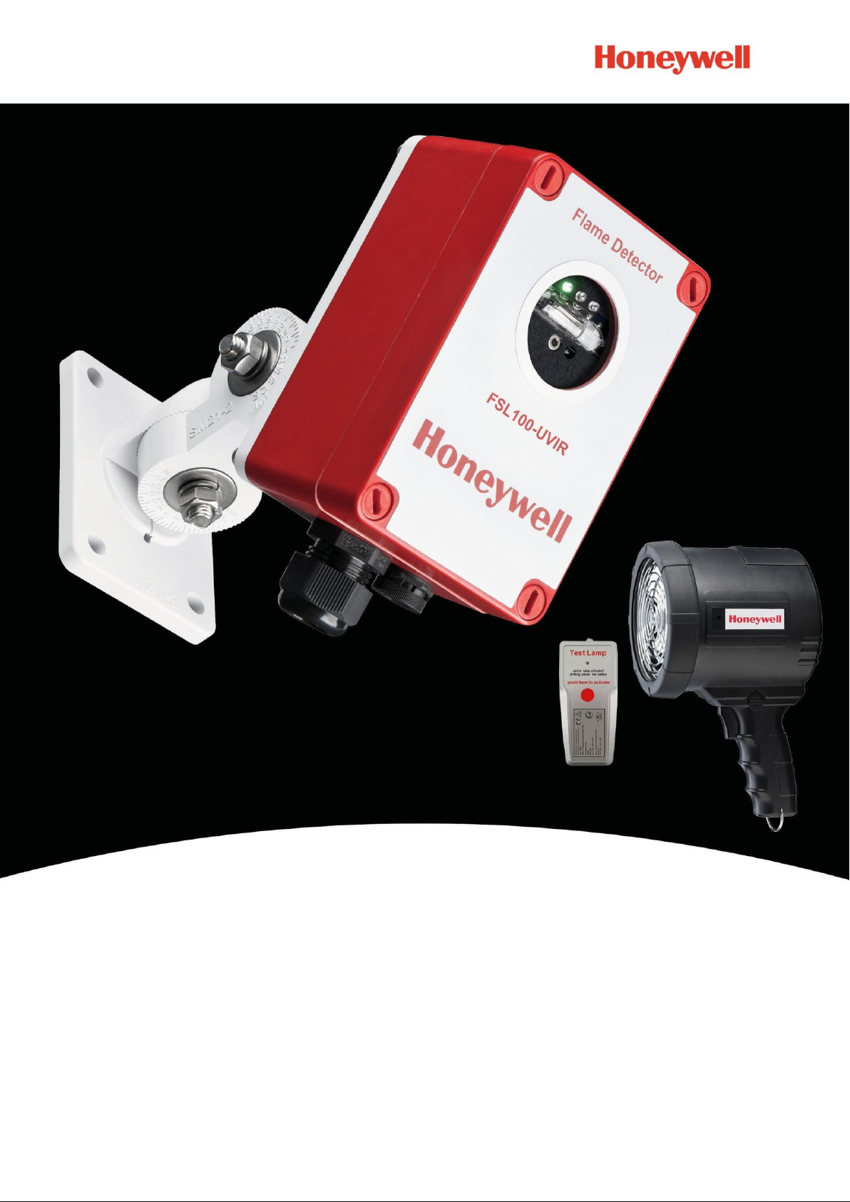
FSL100 SERIES FLAME DETECTORS
AND ACCESSORIES
Page 2

Revision History
ii
Revision
Comment
Date
Issue 01
First Issue
29/07/2015
Issue 02
First Revision
02/09/2016
Issue 03
Page 3

Disclaimer
iii
In no event shall Honeywell be liable for any damages or injury of any nature or kind, no matter how caused, that arise from the
use of the equipment referred to in this manual.
Strict compliance with the safety procedures set out and referred to in this manual, and extreme care in the use of the
equipment, are essential to avoid or minimise the chance of personal injury or damage to the equipment.
The information, figures, illustrations, tables, specifications, and schematics contained in this manual are believed to be correct
and accurate as at the date of publication or revision. However, no representation or warranty with respect to such correctness
or accuracy is given or implied and Honeywell will not, under any circumstances, be liable to any person or corporation for any
loss or damages incurred in connection with the use of this manual.
The information, figures, illustrations, tables, specifications, and schematics contained in this manual are subject to change
without notice.
Unauthorised modifications to the detection system or its installation are not permitted, as these may give rise to unacceptable
health and safety hazards.
In no event shall Honeywell be liable for any equipment malfunction or damages whatsoever, including (without limitation)
incidental, direct, indirect, special, and consequential damages, damages for loss of business profits, business interruption, loss
of business information, or other pecuniary loss, resulting from any violation of the above prohibitions.
Warranty
Honeywell Analytics warrants the FSL100 Series Flame Detection system and accessories against defective parts and
workmanship, and will repair or (at its discretion) replace any components that are or may become defective under proper
usage within 24 months from the date of commissioning by a Honeywell Analytics approved representative* or 30 months from
shipment from Honeywell Analytics, whichever is sooner.
This warranty does not cover consumable, batteries, fuses, normal wear and tear, or damage caused by accident, abuse,
improper installation, unauthorized use, modification or repair, ambient environment, poisons, contaminants or abnormal
operating conditions.
This warranty does not apply to sensors or components that are covered under separate warranties, or to any 3rd-party cables
and components
Any claim under the Honeywell Analytics Product Warranty must be made within the warranty period and as soon as reasonably
practicable after a defect is discovered. Please contact your local Honeywell Analytics Service representative to register your
claim.
This is a summary. For full warranty terms please refer to the Honeywell Analytics’ General Statement of Limited Product
Warranty, which is available on request.
* A Honeywell Analytics approved representative is a qualified person trained or employed by Honeywell Analytics, or a qualified
person trained in accordance with this manual.
Copyright Notice
Honeywell is the registered trademark of Honeywell Safety and Productivity Solutions (SPS).
FSL100 is a registered trademark of Honeywell Analytics (HA).
Other brand and product names mentioned in this manual may be trademarks or registered trademarks of their respective
companies and are the sole property of their respective holders.
Find out more at www.honeywellanalytics.com
Page 4

iv
This page deliberately left blank.
Page 5

CONTENTS
MAN0987_Iss 2_09/16
1
FSL100 Series Flame Detectors
Technical Handbook
Contents
1 Introduction ............................................................................................................................................................................ 3
1.1 Intended Readers ............................................................................................................................................................. 3
2 Safety Hazards, Warnings and Cautions ............................................................................................................................. 5
2.1 General Warnings and Cautions ....................................................................................................................................... 5
2.2 Important Information ........................................................................................................................................................ 5
2.3 FSL100 Safety Features ................................................................................................................................................... 6
3 Overview ................................................................................................................................................................................. 7
4 Mechanical Installation .......................................................................................................................................................... 9
4.1 Siting ................................................................................................................................................................................. 9
4.2 Mounting and Orientation .................................................................................................................................................. 9
4.3 Installing the FSL100 Flame Detectors ............................................................................................................................. 9
4.4 Cone of Vision ................................................................................................................................................................ 10
4.5 Shadow Effect ................................................................................................................................................................. 10
4.6 Mounting Below a Ceiling ............................................................................................................................................... 11
4.7 Vote Count ...................................................................................................................................................................... 12
4.8 Weather Protection ......................................................................................................................................................... 13
4.9 Hot Work ......................................................................................................................................................................... 13
5 Electrical Installation ............................................................................................................................................................ 15
5.1 Power Supply .................................................................................................................................................................. 15
5.2 Cabling Recommendations ............................................................................................................................................. 15
5.3 Earth (Ground) Regimes ................................................................................................................................................. 15
5.4 Wiring Diagram ............................................................................................................................................................... 16
5.5 Electrical Connection (General) ...................................................................................................................................... 17
5.6 Wiring to a Controller (General) ...................................................................................................................................... 17
5.7 Wiring to a Fire Control Panel ......................................................................................................................................... 18
5.8 Wiring to a PLC ............................................................................................................................................................... 19
5.9 Wiring to a 4-20 mA Non-Isolated (Sourcing) Current Output ......................................................................................... 19
5.10 Connecting the Manual Self-Test .................................................................................................................................... 19
5.11 FSL100 Latching Alarm Settings .................................................................................................................................... 20
6 Commissioning and Testing ................................................................................................................................................ 21
6.1 Commissioning ............................................................................................................................................................... 21
6.2 Functional Testing .......................................................................................................................................................... 22
6.3 Fault Analysis ................................................................................................................................................................. 22
6.4 Fault Testing ................................................................................................................................................................... 23
7 FSL100 Operation ................................................................................................................................................................. 25
7.1 The Display LEDs ........................................................................................................................................................... 25
7.2 Normal Operation ........................................................................................................................................................... 25
7.3 Fault Conditions .............................................................................................................................................................. 25
7.4 Relay Outputs ................................................................................................................................................................. 25
7.5 Analogue Output 0–20 mA (Stepped, Sinking, Non-Isolated) ......................................................................................... 25
7.6 Self-Testing..................................................................................................................................................................... 25
7.7 Manual Self-Test ............................................................................................................................................................. 26
8 Maintenance .......................................................................................................................................................................... 27
9 FSL100-SM21 Swivel Mount ................................................................................................................................................. 29
Page 6

CONTENTS
MAN0987_Iss 2_09/16
2
FSL100 Series Flame Detectors
Technical Handbook
9.1 How to Install the Detector Using the Swivel Mounting ................................................................................................... 29
9.2 Cleaning ......................................................................................................................................................................... 30
10 FSL100-TL Test Lamp Non-EX ............................................................................................................................................. 31
10.1 Safety Instructions .......................................................................................................................................................... 31
10.2 Before First Use .............................................................................................................................................................. 32
10.3 Test Lamp Operation ...................................................................................................................................................... 32
10.4 Battery Charging and Storage: ....................................................................................................................................... 32
10.5 Bulb Replacement .......................................................................................................................................................... 33
11 FSL100-TLX Test Lamp Hazardous Areas .......................................................................................................................... 35
11.1 Safety Instructions .......................................................................................................................................................... 35
11.2 Before First Use .............................................................................................................................................................. 36
11.3 Operation ........................................................................................................................................................................ 36
11.4 Battery Replacement ...................................................................................................................................................... 36
12 FSL100 Specifications .......................................................................................................................................................... 37
13 Accessory Specifications ..................................................................................................................................................... 39
14 FSL100 Certifications ........................................................................................................................................................... 41
14.1 EC Declaration of Conformity ......................................................................................................................................... 41
14.2 National and International Certificates of Compliance ................................................................ .................................... 41
14.3 Rating Label .................................................................................................................................................................... 41
14.4 North American approvals – cFMus class 3611 & FM class 3260 .................................................................................. 43
15 Ordering Information ............................................................................................................................................................ 43
16 Returns and Repairs Policy ................................................................................................................................................. 45
17 List of Figures ....................................................................................................................................................................... 47
18 List of Tables ......................................................................................................................................................................... 49
Page 7

MAN0987_Iss 2_09/16
3
FSL100 Series Flame Detectors
Technical Handbook
INTRODUCTION
1
Introduction
This technical manual is available in several languages and it covers the installation, operation and maintenance of the following
equipment:
FSL100-IR3 Flame Detector (Triple Infrared)
FSL100-UV Flame Detector (Ultraviolet)
FSL100-UVIR Flame Detector (Ultraviolet and Infrared)
FSL100-TL Test Lamp, Charger and Case (Safe Areas)
FSL100-TLX Test Lamp, Charger and Case (Intrinsically safe – IECEx, ATEX)
FSL100-SM21 Swivel Mounting
1.1 Intended Readers
This Manual should be read by everyone who operates or monitors the FSL100 Flame Detection system.
Only personnel who have been fully trained by Honeywell are authorised to Install, Set-up, Service, and Test, Repair, or
Recondition Honeywell flame detection systems.
Page 8

MAN0987_Iss 2_09/16
4
FSL100 Series Flame Detectors
Technical Handbook
INTRODUCTION
This page deliberately left blank.
Page 9

MAN0987_Iss 2_09/16
5
FSL100 Series Flame Detectors
Technical Handbook
SAFETY
Caution
Indicates a potentially hazardous situation that, if not avoided, may result in minor or moderate injury. It is also
used to alert the user against unsafe working practices and potential damage to equipment.
Warning
Indicates a potentially hazardous situation that, if not avoided, could result in death or serious injury.
WARNINGS AND CAUTIONS
1. Installation and commissioning must only be carried out by a Honeywell Analytics approved person or by a
qualified person trained in accordance with this manual, and only in accordance with the recognized
regulations and standards of the appropriate authority in the country concerned.
2. Do not make any unauthorised changes to the equipment as essential safety and certification requirements
may be invalidated.
3. Do not operate the detectors in normal conditions with covers open or removed. Access to the interior of the
detector must only be carried out by trained personnel.
4. Ensure the detector power is off and electrically isolated before opening the detector in a hazardous area.
Do not open the enclosure or touch live terminals when the system is energised.
5. Do not touch or contaminate the sensors or lenses as this may shorten their life and may affect their
sensitivity to UV / IR radiation. Clean contaminated sensors and lenses carefully using lint-free or micro-fibre
cloth dampened only with optical-grade cleaning solution.
6. These flame detectors do not require earthing (grounding), but must be installed correctly to avoid electrical
shocks and interference.
7. The FSL100 Flame Detector is only assessed under ATEX for ignition hazards.
8. Operators, site personnel and visitors should be made fully aware of the action to be taken in the event of an
alarm sounding.
Important
Read and understand the instruction manual before operating or servicing the equipment.
2
Safety Hazards, Warnings and Cautions
2.1 General Warnings and Cautions
2.2 Important Information
This manual is for use with FS100 Series Fire Detectors only.
Honeywell Analytics can take no responsibility for installation and/or use of its equipment if not done so in accordance with the
appropriate issue and/or amendment of the Operating Manual.
The reader of this Manual should ensure that it is appropriate in all details for the exact equipment to be installed and/or
operated. If in doubt, contact Honeywell Analytics for advice.
The following types of notices are used throughout this Operating Manual:
Page 10

MAN0987_Iss 2_09/16
6
FSL100 Series Flame Detectors
Technical Handbook
SAFETY
Every effort has been made to ensure the accuracy of this document; however, Honeywell Analytics can assume no
responsibility for any errors or omissions in this document or their consequences.
Honeywell Analytics would greatly appreciate being informed of any errors or omissions that may be found in the content of this
document.
For information not covered in this document, or if there is a requirement to send comments/corrections about this document,
please contact Honeywell Analytics using the contact details given on the back page.
Honeywell Analytics reserve the right to change or revise the information supplied in this document without notice and without
obligation to notify any person or organization of such revision or change. If information is required that does not appear in this
document, contact the local distributor/agent or Honeywell Analytics
2.3 FSL100 Safety Features
The FSL100 has the following safety features:
Hazardous area certified: ATEX Zone 2/22, FM Class 1, 2, 3 Div. 2
Performance certified: EN54-10 and FM 3260
Robust Glass Reinforced Polyester (GRP) housing, which is available in standard red housing or white housing options and
is:
o Light weight but impact resistant
o Weather sealed and incorporating pressure compensating breather
o Non-Incendive (flameproof), non-corrosive and UV resistant
Automatic Sensor self-test continuously monitors the sensors, electronics and firmware for proper operation
Manual Self test initiated by contact closure
Relay and mA sink outputs and selectable latching / non-latching alarm relay outputs
Local status LEDs
Optional (safe area or hazardous area) Function Test Lamps to enable simple coverage and operational checks of the
Honeywell FSL100 series Flame Detectors (with long range test source detection)
Page 11
MAN0987_Iss 2_09/16
7
FSL100 Series Flame Detectors
Technical Handbook
OVERVIEW
UV
Visible
Near IR
IR
Thermal IR
Far IR
3
Overview
The Honeywell Analytics FSL100 series of Flame Detectors comprises three models:
FSL100-IR3 Triple Infrared flame detector
FSL100-UV Ultraviolet flame detector
FSL100-UVIR Ultraviolet and Infrared flame detector
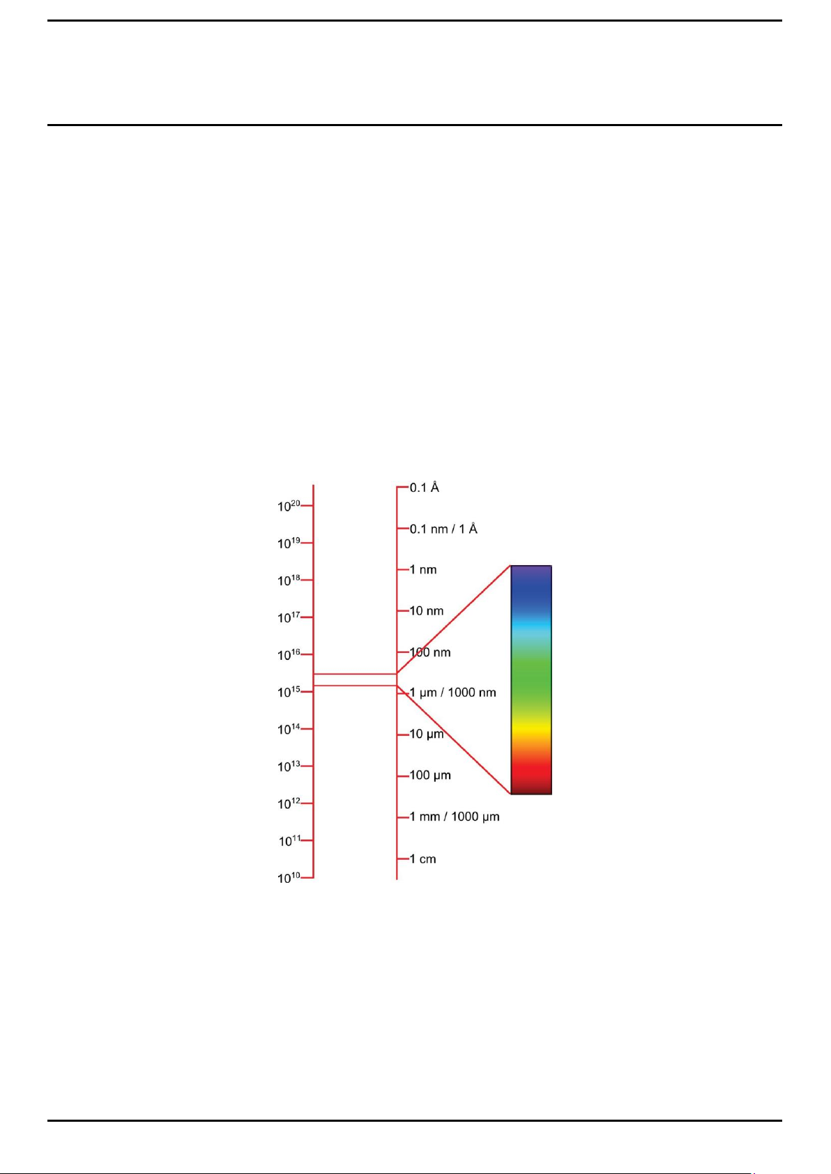
These flame detectors monitor an area by looking for the presence of invisible infrared or ultraviolet light that occur outside the
frequency range occupied by visible flames, and they can do this in the presence of interference (sunlight, smoke, dust, vapour
etc.) to determine whether or not a fire is actually present within their field of view.
All three detectors utilize a microprocessor for sophisticated electronic signal analysis. Detectors with IR sensors also analyse
the flame flicker effect. The Triple IR flame detector uses this method to give highly reliable nuisance alarm rejection and is also
less affected by optical contamination and smoke than are UV based flame detectors.
The diagram below shows the spread of invisible UV/IR radiation that is available for sampling outside the human visual range,
and shows how a UV/IR detector can be potentially 1 million times more sensitive than a human eye.
Frequency (Hz) Wavelength
Note: Monitoring a fire zone (i.e. a fume chamber) through its glass or acrylic walls could reduce or defeat the sensitivity of
certain types of flame detector.
For example, plain glass and acrylic are known to block IR but may transmit UV, whereas coated materials may block both.
Please consult Honeywell Analytics Technical Support for further information if you need this type of application
Figure 1. Comparison of Visible Radiation Range to UV/IR Radiation Range
Page 12

MAN0987_Iss 2_09/16
8
FSL100 Series Flame Detectors
Technical Handbook
OVERVIEW
This page deliberately left blank.
Page 13
MAN0987_Iss 2_09/16
9
FSL100 Series Flame Detectors
Technical Handbook
INSTALLATION
4
Mechanical Installation
This chapter describes the mechanical requirements for installing FSL100 Series Flame Detectors. Electrical
installation is discussed in the next chapter.
4.1 Siting
The number, type and placement of fire detectors and alarm control systems should be determined in consultation with
Honeywell Analytics specialist technical advisors and Site specialists.
Remember that the FSL100 series are flame detectors only; they cannot detect flammable gas or dust atmospheres. Please
contact Honeywell Analytics if you need a flammable atmosphere detection system.
Generally speaking, one or more FSL100 flame detectors should be positioned on walls or posts above the monitored object or
area, and they should overlap so that shadow areas cannot occur (see diagrams that follow).
4.2 Mounting and Orientation
In this chapter a number of general guidelines are given for the flame detector system design. Several of these guidelines are
discussed in more detail in the following chapters.
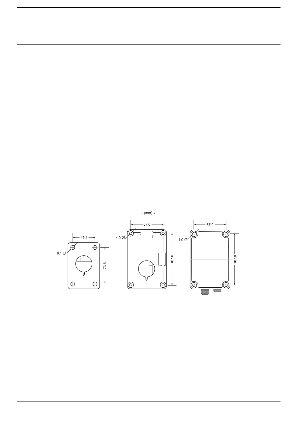
4.3 Installing the FSL100 Flame Detectors
There are 2 options for installing the FSL100 series of Flame Detectors:
1. You can use the optional Swivel Mount to mount them on walls, ceilings or posts (see Ch.10 FSL100-SM21 Swivel Mount).
2. You can mount them directly to a ceiling (i.e. in a fume chamber or in an engine room) or inside ducting.
Use the measurements below for mounting, remembering to allow clearance for the cables.
FSL100-SM21
Swivel Mounting
Wall Plate
Figure 2. Mounting Hole Dimensions
FSL100-SM21
Swivel Mounting
Back Plate FSL100 Detector
Page 14
INSTALLATION
MAN0987_Iss 2_09/16
10
FSL100 Series Flame Detectors
Technical Handbook
45
o
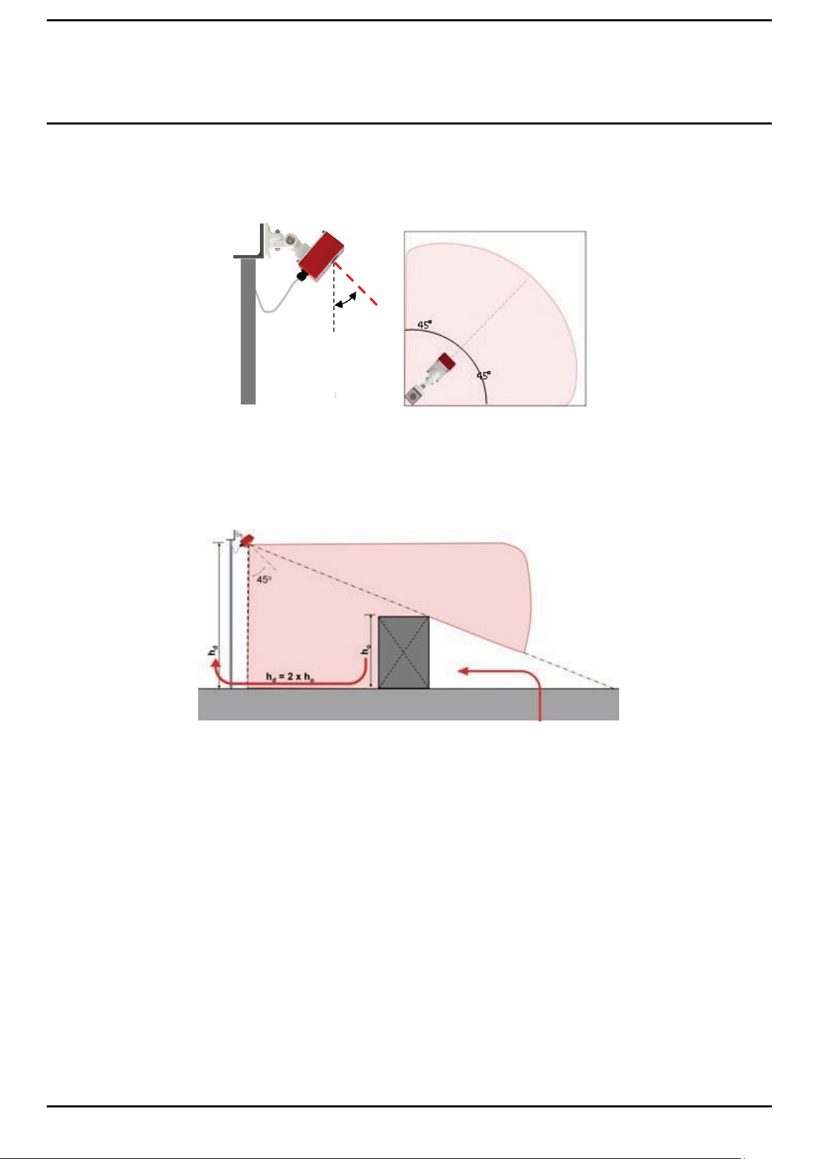
4.4 Cone of Vision
The FSL100 flame detector has a cone of vision of 90° so it can monitor an area extending from floor to ceiling and
extending to approximately 23 m (FSL100-UV and UVIR) or 35 m (FLS100-IR3).
Figure 3. Cone of View
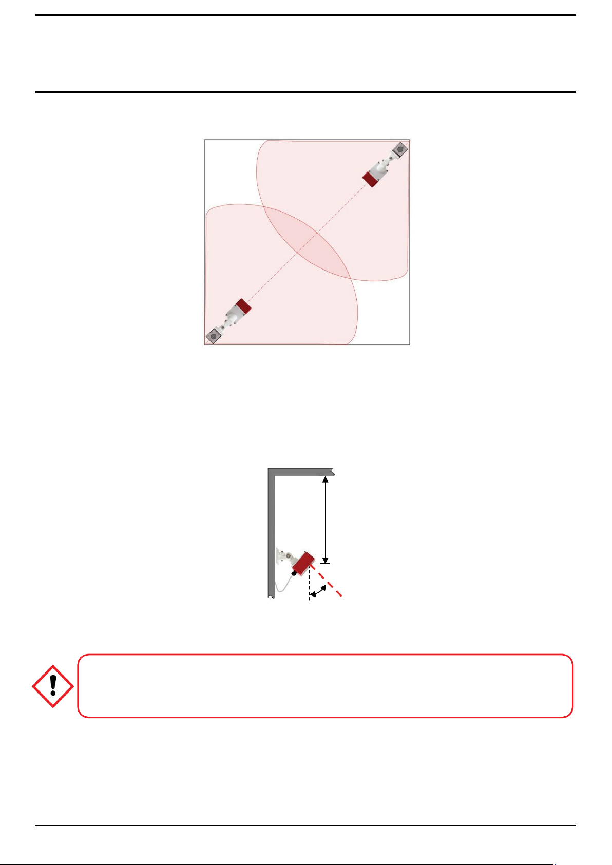
4.5 Shadow Effect
If monitoring a solid object, the mounting height (hd) of the flame detector should be at least twice the height (ho) of the highest
object in the monitored zone:
Detector height (hd) = 2 x height of the highest object (ho) Shadow effect
Figure 4. Shadow Effect
Page 15
INSTALLATION
MAN0987_Iss 2_09/16
11
FSL100 Series Flame Detectors
Technical Handbook
Caution
Reducing the height of a detector above the monitored item will increase the size of shadow areas, so a
minimum of two detectors will be required to cover the shadows. See Shadow Effect explanation above.
D m
45
o
To avoid the shadow effect (in zones that cannot be fully monitored by a solo flame detector) place a second flame detector in
the opposite corner.
Figure 6. Shadow Cancelling
4.6 Mounting Below a Ceiling
Smoke rises and can form a layer at ceiling height long before naked flames are visible. Dense smoke can block some of the
wavelengths of light given off by flames, and this can ultimately decrease the sensitivity and speed of the flame detector.
To avoid the risk of smoke blocking their fields of view, you should mount the FSL100-IR3 flame detectors at least 0.5 m (2 ft),
and the FSL100-UV and FSL100-UVIR detectors at least 1.5m (6 ft), below the ceiling (see dimension ‘D’ below).
Figure 7. Mounting Clearance
Page 16
INSTALLATION
MAN0987_Iss 2_09/16
12
FSL100 Series Flame Detectors
Technical Handbook
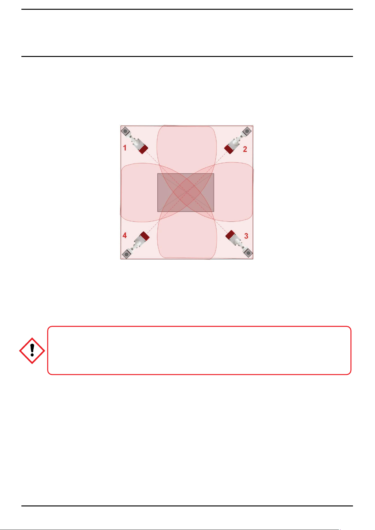
Caution
A flame detector is a line of sight detector so voting with just two flame detectors in not reliable. The redundant
flame detector in the opposite corner cannot be used for a 2 detector dependent output because a flame
occurring in a shadow area would not be seen by the second detector until the fire is well established. In this
case the second flame detector will give an alarm too late or not at all.
Monitored object
4.7 Vote Count
FSL100 flame detectors will not give an alarm until several different alarm criteria occur at the same time, and the probability of
a false alarm is very low. The flame detector is therefore suitable for relay activated actions (i.e. drenching) based on the signal
of one flame detector.
However, ‘voting’ may be demanded in a functional specification, in which case the ‘voting-system’ may be applied; i.e., the
flame detectors may be mounted in multiples, as shown in the example below where an alarm output would be dependent on
the controller receiving confirmatory alarm inputs from at least two of the available detectors.
Figure 8. Voting Arrangement Using Four Detectors
A good example of voting would be in a Server room or process room that uses inert gas drenching to replace oxygen in the
atmosphere, and the voting of any 2 out of the 4 flame detectors should be mandated before the relay output can be triggered.
Note: The fire control panel or PLC must be able to support the two detector voting system.
Page 17

INSTALLATION
MAN0987_Iss 2_09/16
13
FSL100 Series Flame Detectors
Technical Handbook
4.8 Weather Protection
It is recommended to place a hood or shield above the flame detector to protect it from sunlight, rain and snow. A stainless steel
metal plate of approximately 30 x 30 cm (12 x 12 in) can be mounted directly above the flame detector without inhibiting its field
of view. A similar plate can be used to shield it from potential false alarm sources such as smoke-stack flares.
4.9 Hot Work
Flame Detectors may alarm in the presence of hot work, for example a welding operation, and this must be taken into
account when doing Hot Work risk assessments and when issuing Hot Work permits.
Usually it is sufficient to inhibit or isolate the alarm system in that area and substitute a ‘Fire Marshall’ or safety man armed with
an appropriate fire extinguisher.
Page 18

INSTALLATION
MAN0987_Iss 2_09/16
14
FSL100 Series Flame Detectors
Technical Handbook
This page deliberately left blank.
Page 19

INSTALLATION
MAN0987_Iss 2_09/16
15
FSL100 Series Flame Detectors
Technical Handbook
Typical Cable Data
Maximum Cable Length (L)
Cable size
(cross sectional area)
Cable resistance
Ω/km (Ω/mile)
Metres
Feet
0.5 mm2 ≅ 20 AWG
36.8 (59.2)
245
808
1.0 mm2 ≅ 17 AWG
19.5 (31.4)
462
1516
1.5 mm2 ≅ 16 AWG
12.7 (20.4)
709
2326
5
Electrical Installation
5.1 Power Supply
Table 1. FSL100 Cable Data
Note: Safety margins should include an allowance for resistance changes due to changes in T ambient over time. I.e. Higher
temperature = higher resistance, while resistance may increase due to oxidation or loss of ductility over time.
5.2 Cabling Recommendations
The FSL100 Flame Detector is supplied fitted with a suitable gland. The use of industrial grade, screened and suitably armoured
field cable is recommended.
For example, three core copper cable, with screen (90% coverage) and suitable mechanical protection (i.e. insulated steel wire
armour) to suit M20 gland entry.
The maximum conductor size for the terminals is 1.5 mm2 (16 AWG).
Ensure the cable gland is installed correctly and fully tightened. All unused cable/conduit entries must be sealed with a suitable
certified sealing plug.
5.3 Earth (Ground) Regimes
Please note:
Controllers should be connected to protective earth (ground) via an isolator switch that cannot disconnect the earth line.
Field cable screens should be connected to instrument earth (ground) in the controller only. The other end of the field cable
screen shall be cut and isolated.
Field cable armour / conduit shall be insulated from the cable screening and earthed (grounded).
Avoid earth (ground) loops at all times.
Page 20

INSTALLATION
MAN0987_Iss 2_09/16
16
FSL100 Series Flame Detectors
Technical Handbook
Terminal
Input
Terminal
Input
1
+10 to +28 VDC Input
10
NC Alarm
2
–Ve Input
11
NC Fault
3
Not in use
12
MC Fault
4
Not in use
13
NO Fault
5
Not in use
14
+10 to +28 VDC Manual Self Test Input (>5 s)
6
Not in use
15
EOL Resistor
7
4–20 mA Sink Output
16
AL Resistor
8
NO Alarm
17
EOL Resistor
9
MC Alarm
18
AL Resistor
5.4 Wiring Diagram
Terminal 1 has a Blocking Diode for reverse polarity protection and a Multi-fuse for overcurrent protection.
Figure 9. FSL100 Wiring Diagram (Power On – Normal)
Table 2. FSL100 Terminal Allocation
Page 21

INSTALLATION
MAN0987_Iss 2_09/16
17
FSL100 Series Flame Detectors
Technical Handbook
Warning
The cable Earth (Ground) core must be connected to Protective Earth via the Controller power supplies, and the
cable screen must be connected to the controller’s common earth (ground) point.
The cable armour or conduit must be bonded to Protective Earth at regular intervals while being isolated from
the cable screen, cores and controller.
Avoid earth (ground) loops at all times.
5.5 Electrical Connection (General)
The flame detector has several wiring options; the most important are:
1. Wiring to a fire control panel using the ‘current increase’ principle.
2. Wiring to a PLC using a 0-20 mA output.
3. Wiring with an additional manual self-test.
4. Stand-alone wiring, with direct use of relays.
Options 1 to 3 are explained in this chapter, and Option 4 is shown in Chapter 5.4 Wiring Diagram.
5.6 Wiring to a Controller (General):
1. Use multi-core, shielded, twisted pair cable with earth (ground), depending on the panel and the type of connection. The
isolation resistance to ground must be at least 500K Ohm.
2. Core size must be 0.5 to 1.5 mm2 (20 to 16 AWG).
3. The length and diameter of the wires should be selected so that the flame detector will have sufficient power under all
conditions (normal and alarm) to ensure that the operating voltage is never below 10 VDC, especially when in alarm mode.
4. On the flame detector side of the cable leave a 10 cm (4 in) loop of spare cable to allow for alignment of the detector.
5. Grounding on the flame detector side: ensure that the screen cannot make an electrical connection with ground or with the
electronics in the detector housing. Ensure that the electronics in the flame detector housing are isolated from local ground
to avoid potential differences (ground loops).
6. Do not connect more than one flame detector per loop.
The flame detector has a cable gland fitted with an 8 mm insert. Use the cable gland with the insert for cables from 5.5 – 8 mm
diameter. Remove the insert for cables of 8 – 13 mm diameter.
Figure 10. FSL100 Cable Gland with and without Cable Entry Insert
Page 22

INSTALLATION
MAN0987_Iss 2_09/16
18
FSL100 Series Flame Detectors
Technical Handbook
Isola
alarm
shrin
te EOL and
resistors with
kable tubing
FLT
Alarm
EOL
Loop Power
Isolate EOL and
Alarm resistors
with Heatshrink
5.7 Wiring to a Fire Control Panel
The flame detector can be connected to a fire control panel using the current increase principle.
The flame detector is connected to the fire panel with 3 or 4 core cables, i.e. 2 cores for the power supply and 1 or 2 cores for
the loop. An additional core for the manual self-test may be used (see the FSL100 Terminal Connection Diagram).
The end of line resistor (EOL) is placed between the terminals 15 and 17. The alarm resistor (AL) is placed between terminals
16 and 18. The end of line and alarm resistors should be adapted to the fire control panel. They are approximately the same
size resistors that are used when connecting a manual call point to a fire control panel.
Controller
Alarm
EOL
Loop
Loop
Alarm
Alarm
Power
Screen end
isolated from
detector and
earth (ground)
Screen end
connected to
system earth
(ground)
Screened cable
Operating Principle:
The loop uses the alarm contact and the fault contact of the flame detector plus two resistors. In the event of a detector fault a
wire breakage is simulated. In the event of a fault followed by an alarm, a current Vn/AL is flowing through the loop. Thus an
alarm ‘overrides’ a fault signal, as can be seen in the figure.
Notes:
1. Please consult the fire control panel manufacturer for the values of the Alarm and EOL resistors.
2. The alarm and EOL resistor must be rated 2 W minimum each, and the total power dissipation of both alarm and EOL
resistor should not exceed 2 W. Use heat shrink tubing to insulate the legs of the EOL and the AL resistor when in-situ.
3. Do not connect more than one flame detector to a loop.
Figure 11. FSL100 to Controller Wiring
Power On, Normal
Page 23

INSTALLATION
MAN0987_Iss 2_09/16
19
FSL100 Series Flame Detectors
Technical Handbook
5.8 Wiring to a PLC
PLC
R = max
500Ω at
24 VDC
Screen end
isolated from
detector and
earth (ground)
Screen end
connected to
system earth
(ground)
Figure 12. Wiring to a PLC
Notes
1. 0-20 mA sinking analogue output, non-isolated.
5.9 Wiring to a 4-20 mA Non-Isolated (Sourcing) Current Output
The FLS100 detectors can be wired to a 4-20 mA non-Isolated (Sourcing) Output by using the controller’s alarm and fault
relays, as shown below.
Figure 13. Wiring to a 0-20 mA Non-Isolated (Sourcing) Current Output
The 4-20 mA sourcing output has the following values:
≥4 mA = Normal operation
≥20 mA = Alarm
0 mA = Fault (the 0 mA current will change to ≥20 mA (alarm) if flames are detected while the source is in fault)
Note:
This configuration has 2 wires connected to T1, but you should check if this is forbidden by your local regulations.
Page 24

INSTALLATION
MAN0987_Iss 2_09/16
20
FSL100 Series Flame Detectors
Technical Handbook
ON
OFF
5.10 Connecting the Manual Self-Test
A manual self-test switch can be incorporated by supplying a +10 to +28 VDC switched current to terminal 14 in the detector.
This switch can be integral or external to the Fire Control panel or the PLC.
Figure 14. Manual Self-Test Switch Locations
5.11 FSL100 Latching Alarm Settings
The FSL100 uses DIL switch 3 for field selectable alarm latching or unlatching. The default setting is latching ON, and DIL
switches 1, 2 and 4 are currently unused.
To change alarm status, change the DIL switch, and then power off for >1 second before switching back on again.
This setting is standard for fire control panels in conformity with the European standard EN54. However, you should always read
your controller’s handbook as some systems can control alarm latching status by software, in which case there is no need to
reset the detector by powering it off.
Figure 15. Latching Alarm Settings
Latching alarm Non-Latching alarm
Page 25

COMMISSIONING
MAN0987_Iss 2_09/16
21
FSL100 Series Flame Detectors
Technical Handbook
Caution
Always ensure that relay operated outputs and alarms are inhibited or isolated before carrying out any work on
Alarm systems.
Always ensure that Alarm Systems are returned to Normal Operation when work is completed.
6
Commissioning and Testing
Notes:
1. Commissioning, maintenance and functional testing of Honeywell Fire Detection systems must only be carried out by
qualified Honeywell approved persons or qualified persons trained in accordance with this manual.
2. All local laws and regulations for the commissioning and the cabling apply, including law and regulations for activating
alarm systems, extinguishing systems and other outputs.
3. For hazardous area applications appropriate regulations shall be followed.
4. The IR sensors can become saturated if exposed to high ambient IR radiation, so ensure that the FSL100 detectors are
shielded from potential sources such as boilers, radiators and IR lamps. The FSL100 detector returns to normal within 10
seconds once the IR source is removed.
6.1 Commissioning
Carry out the following steps before the flame detector is activated for the first time and in conjunction with the associated
Controller or PLC’s Technical Manual:
1. Satisfy yourself that the chosen FSL100 is the correct choice for this situation, location and controller.
2. Clean the FSL100 window using a microfiber glass cloth or optical wipe.
3. Check the terminals, seals and cable gland, and then close and secure the FSL100 housing.
4. Check position and alignment.
5. Check if there are potential false alarm sources in the field of view and shield if necessary.
6. Thoroughly tighten the cable gland and all fasteners.
7. Check the cabling in between the FSL100 and the controller.
8. Check the controller is electrically safe (isolator, protective earth (ground) etc.)
9. Check the cable screening is correctly bonded to the controller.
10. Check that armoured conduit is earthed (grounded) but isolated from the cable screen.
11. Test the manual self-test by shorting FSL100 terminals 1 & 14 for approximately 5 seconds.
12. Perform a functional test with the FSL100-TL or FSL100-TLX test lamp even if the manual test was ok.
13. If satisfied, and when all detectors are commissioned and tested, set the Controller or PLC to normal operation.
Page 26

COMMISSIONING
MAN0987_Iss 2_09/16
22
FSL100 Series Flame Detectors
Technical Handbook
Warning
A user-defined performance requirement may stipulate that an actual (real) fire performance test is carried out
from time-to-time. Ensure that a Safe System of Work is used to avoid the risk of death, injury or damage to
property.
Caution
Always ensure that relay operated outputs and alarms are inhibited or isolated before carrying out any work on
Alarm systems.
Always ensure that Alarm Systems are returned to Normal Operation when work is completed.
6.2 Functional Testing
The FSL100 flame detector has been tested in the factory and shall be tested as part of installation and commissioning. In
addition the flame detector should be functionally tested regularly (i.e. weekly) as part of a site fire alarm test. Check and clean
the FSL100 window prior to testing. Contamination lowers the sensitivity of the flame detector and can build up over time if not
monitored and cleaned regularly.
Honeywell supplies the FSL100-TL (safe area) and FSL100-TLX (hazardous area) test lamps for the FSL100 series of flame
detectors. Please read the test lamp instructions in this manual before you start the functional test.
6.3 Fault Analysis
False alarms may be triggered by transient events or because:
1. The sensor is activated by a known or unknown source in its field of view.
2. The sensor is activated by electromagnetic interference.
3. The sensor is activated by cabling faults or damage (may be intermittent).
4. The sensor electronics are faulty.
A single false alarm should not cause undue concern, but a series of false alarms should be carefully investigated to rule out the
causes listed above. You should also consider other factors such as season, weather, time of day, ambient temperature or
humidity, angle of the sun, etc.
Page 27

COMMISSIONING
MAN0987_Iss 2_09/16
23
FSL100 Series Flame Detectors
Technical Handbook
Caution
Always ensure that relay operated outputs and alarms are inhibited or isolated before carrying out any work on
Alarm systems.
Always ensure that Alarm Systems are returned to Normal Operation when work is completed.
6.4 Fault Testing
Refer to the manufacturer’s instructions before carrying out any testing as some controllers require sensors to be
decommissioned before removal or replacement.
1. Always follow a structured fault analysis and test regime.
2. Check the suspect FSL100 for signs of displacement, contamination, damage, loose or damaged cables, transient sources
etc.
3. Cover the FSL100 optics to ensure that no light or other radiation can reach the sensor and wait 30 seconds for the sensor
to return to normal. A continuing alarm state may be caused by the cabling or by the electronics. Ensure that the detector
window is uncovered after this test.
4. Check off the items listed in the section on Commissioning.
5. Check the power supplies; cables, voltage, current, ripples on the voltage signal etc.
6. Replace the flame detector with a known serviceable spare and re-test.
Page 28

COMMISSIONING
MAN0987_Iss 2_09/16
24
FSL100 Series Flame Detectors
Technical Handbook
This page deliberately left blank.
Page 29

MAN0987_Iss 2_09/16
25
FSL100 Series Flame Detectors
Technical Handbook
OPERATION
7
FSL100 Operation
7.1 The Display LEDs
The FSL100 series flame detectors have 3 LEDs on the display:
Steady green: powered up and in normal operation
Steady yellow: fault (blinking yellow: repeated self-test after a self-test fault)
Steady red: alarm
7.2 Normal Operation
The green LED is on when power is applied and the detector is in normal operation.
Fire Alarm
The green normal operation LED turns off and the red alarm LED turns on whenever the detector senses an alarm condition
and (under default settings) the alarm will remain latched (held on) until the event is cleared and either the alarm is reset at the
controller or the detector’s power is cycled.
Alternatively, if the latch setting has been changed to ‘unlatched’ the detector will return to normal operation once the alarm
trigger event has been removed.
Note: Optional alarm system relay outputs may be triggered during an alarm condition.
7.3 Fault Conditions
The yellow and green LEDs are illuminated when a fault condition occurs. The yellow LED turns off as soon as the fault is
cleared.
The green and yellow LEDs turn off and the red LED turns on if an alarm occurs during a non-critical fault condition (i.e. during
an IR or UV lamp test).
A blinking yellow LED shows that a self-test is in progress. The LED will become steady yellow if the FSL100 repeatedly fails
self-test.
7.4 Relay Outputs
The flame detector has 2 relay outputs:
1. Alarm relay (SPDT) that can be used to operate an alarm or relay controlled event. It can be changed from Latching
(default) to Unlatched. A latched alarm can be reset by using controller software or by cycling the detector power off and
on.
2. Fault relay (SPDT). The fault relay is energized when the detector is powered up and will be de-energized in the event of a
fault. The fault relay is non-latching.
7.5 Analogue Output 0–20 mA (Stepped, Sinking, Non-Isolated)
The analogue output has the following possible values:
0 mA power fault / microprocessor fault
2 mA optical fault
4 mA normal operation
20 mA Alarm
The output defaults to 20 mA if, during a fault, the FSL100 detects a fire.
7.6 Self-Testing
The FSL100 carries out a Power On Self Test (POST), and the 3 LEDs will flash sequentially until it is completed (10 Seconds)
The LED sequence is replaced by a steady green LED If the detector passes the test.
While powered up, an optical self-test is periodically and automatically executed to monitor the electronics and the sensor(s).
During this short test the yellow LED may flash and the FSL100 outputs are temporarily inhibited. The test may repeat several
times if a sensor fails the optical self-test.
The yellow fault LED will be steady and the fault relay will de-energize if the fault condition remains after the repeated self-tests.
Page 30

MAN0987_Iss 2_09/16
26
FSL100 Series Flame Detectors
Technical Handbook
OPERATION
Caution
Always ensure that relay operated outputs and alarms are inhibited or isolated before carrying out any work on
Alarm systems.
Always ensure that Alarm Systems are returned to Normal Operation when work is completed.
7.7 Manual Self-Test
The flame detector can test the sensor(s) and also the signal processing with help of the optional manual self-test circuit.
During a successful manual self-test the alarm relay is energized and the red alarm LED illuminates. If the detector is latched,
the alarm continues until the detector is powered off.
For the manual self-test a switch can be mounted in the controller or connected externally to a +10 to +28 VDC supply. (See Ch.
6.5 Connecting the Manual Self-Test.)
During commissioning this option can be tested by shorting the FSL100 terminals 1 & 14 for 5 seconds maximum.
1. The manual self-test can be used during commissioning to test the detector without the necessity to use a flame detector
test lamp.
2. The manual self-test is not a replacement for the functional test using a test lamp. After the commissioning is completed,
the flame detectors must be functionally tested by means of a test lamp.
Page 31

MAN0987_Iss 2_09/16
27
FSL100 Series Flame Detectors
Technical Handbook
MAINTENANCE
Warning – Explosion Hazard
Rubbing the GRP housing or mounting may cause static discharges that can result in an explosion in a
combustible atmosphere.
In hazardous areas use only a clean, damp cloth (moistened with water) to clean the mounting and detector.
8
Maintenance
Periodically inspect FSL100 and cabling for signs of physical damage. Do not use solvents or abrasive cleaners on the detector
housing or optics. Clean only with microfiber cloths moistened with water, or use optical grade wipes.
FSL100 has no user serviceable parts. Honeywell Analytics recommends that the unit is checked and serviced annually by an
approved Honeywell field technician.
Except for cleaning there is no specific preventive maintenance needed. Routine inspection of the following items is
recommended as follows:
1. Check the position and the alignment of the flame detectors.
2. Check there are no potential false alarm sources in the field of view.
3. Check there are no obstacles which restrict the field of view.
4. Clean the detector window with a microfiber cloth (see above).
5. Ensure that the cover of the housing (with detector window) is mounted correctly on the housing. The sensors must be
visible when you look through the detector window.
6. Check the cabling and conduits from the flame detectors to the controller for damage, insecurity, loose connections,
especially at earth (ground) points.
7. Check the cover and the gland are secure and undamaged to protect the IP rating.
8. Check that all fasteners and the cable gland are tight and secure.
9. Perform a functional test with help of an FSL100-TL or FSL100-TLX test lamp.
10. Ensure that once a year the inner side of the detector window is cleaned (i.e. during a field service technician’s annual
inspection).
Note:
1. The user is responsible for keeping the equipment in optimal condition. Contact Honeywell Analytics Technical Support if
you have any concerns about the serviceability or operation of the FSL100 Flame detectors, or if you need help with this
manual.
2. Do not use a liquid cleaning agent for cleaning the flame detector.
3. Your local Honeywell representative or distributor will be happy to advise you about keeping replacement Flame Detectors
or Test Lamps.
Page 32

MAN0987_Iss 2_09/16
28
FSL100 Series Flame Detectors
Technical Handbook
MAINTENANCE
This page deliberately left blank.
Page 33

MAN0987_Iss 2_09/16
29
FSL100 Series Flame Detectors
Technical Handbook
ACCESSORIES
2-Axis Swivel
Detector
Cable gland
always points
downwards
Warning – Explosion Hazard
Rubbing the GRP housing or mounting may cause static discharges that can cause an explosion in a
combustible atmosphere.
Use only a clean, damp cloth (moistened with water) to clean the mounting and detector.
Detector
Window
9
FSL100-SM21 Swivel Mount
The optional swivel mount is a convenient mounting device for fixing the FSL100 series of flame detectors to a variety of
surfaces or poles. The two axis swivel enables you to accurately align the detector’s field of view to the area of fire risk, or you
can use it to increase the detector’s stand-off from the mounting surface (i.e. for cooling and ventilation).
The FSL100-SM21 swivel mount is suitable for Hazardous Area applications, but see the Warning below.
9.1 How to Install the Detector Using the Swivel Mounting
Installation should be carried out by qualified persons only, and in conjunction with the instructions in this handbook.
Tools required:
13 mm wrench
7 mm wrench
#7 screwdriver
Wall plate
Figure 16. Swivel Mounting Fitment (Optional)
1. Unbolt either of the two swivel joints to make it easier to fix the detector to the mounting plate later on.
2. Mount the wall plate to a vibration free wall, ceiling or pole using 4 suitable fixings (not supplied).
3. Carefully undo the four plastic screws at the corners of the detector cover plate, and gently separate the cover from the
body. Be careful not to touch or damage the electronics inside.
4. Locate and remove the four steel bolts shown in the figure above. Use these bolts to secure the detector body to the swivel
mounting plate, ensuring that the screw heads are fully seated in the body recesses, that the swivel hub is closest to the
cable gland, and that the cable gland will point downwards when fully assembled.
5. Reconnect the swivel joint and tighten the bolt finger tight.
6. Connect the power/signal cable (see Wiring to a Controller (General)) and tighten the cable gland.
7. Place the cover of the detector on the housing and carefully tighten the four red plastic screws to 2 Nm (1.5 ft/lb) torque.
Note: The sensors should be clearly visible through the detector window.
8. Adjust the detector to the correct orientation and fully tighten the two swivel bolts.
9. Check that all is secure and correctly fitted, and then test (with a Honeywell approved test lamp) to ensure that the
operation is correct.
Page 34

ACCESSORIES
MAN0987_Iss 2_09/16
30
FSL100 Series Flame Detectors
Technical Handbook
Wall Plate
Detector Plate
Figure 17. SM21 Swivel Mount Attachment Plate Dimensions
9.2 Cleaning
Only experience of the operating environment will dictate how often you clean your detectors and mountings, but you should
remove contamination by wiping the mounting, detector and detector window regularly with a lightly dampened micro-fibre cloth.
Do not use dry cloth or dry paper in flammable atmospheres as this may cause static discharge that may result in an explosion.
Remember that airborne dusts can be more hazardous than flammable vapours.
Used cleaning cloths may be hazardous to health, so launder them carefully or dispose of them as hazardous waste.
Page 35

ACCESSORIES
MAN0987_Iss 2_09/16
31
FSL100 Series Flame Detectors
Technical Handbook
Warning – Safe Areas Only
The FSL100-TL test lamp is only compatible with the Honeywell Analytics FSL100 series flame detectors used
in safe areas. The test lamp is not approved for use with any other types of detector or location.
Always ensure that relay operated systems (drenchers, alarms, etc.) are inhibited or disabled before operating
this test lamp in the vicinity of any flame detector.
Always ensure that Alarm Systems are returned to Normal Operation when work is completed.
10
FSL100-TL Test Lamp Non-EX
The FSL100-TL (test lamp) is a rechargeable, hand-held IR and UV radiation source that is specifically designed to test
Honeywell FSL100 series flame detectors used in safe areas only. The detection range is approximately 4 meters (13 ft).
It is supplied in a custom carry case with a dedicated charging unit suitable for mains connection.
10.1 Safety Instructions
Read this manual carefully and study the warnings and cautions before using this equipment.
1. This test lamp is only suitable for testing Honeywell FSL100 series flame detectors in safe areas.
2. Do not use the test lamp in wet conditions.
3. Ensure testing of the flame detectors does not activate unwanted alarm signals.
4. Press the trigger to switch on, release it to switch off.
5. Batteries may be damaged if you use the test lamp continuously for longer than 10 minutes.
6. The grid may become hot during use. Be careful not to allow contact with skin or flammable objects.
7. Do not touch or remove the protective grid or stick fingers or objects through it.
8. Do not point directly at eyes from a short distance. Do not look directly into the light.
9. Store the test lamp in its box in a clean and dry location. A dirty reflector will reduce the test range.
10. Do not incinerate or mistreat the lamp or battery as the battery could leak or explode.
11. The test lamp should not be used when damaged. If a fault does occur, do not open the lamp other than to change the
battery. Return faulty lamps to Honeywell Analytics for repair.
12. Keep the test lamp and batteries away from children. Dispose of items in accordance with the WEEE directive.
Figure 18. FSL100-TL Test Lamp Kit
Page 36

ACCESSORIES
MAN0987_Iss 2_09/16
32
FSL100 Series Flame Detectors
Technical Handbook
Caution
Test outputs will be generated and relays will be activated during Cause and Effect Testing.
Ensure that relay activated output systems (i.e. emergency deluge / sirens etc.) are inhibited or isolated before
starting the test.
Ensure that the system is returned to normal operation once testing is complete
Caution – WEEE Directive
According to local laws and regulations batteries should be disposed of separately from household waste. Take
them to a collection point designated by local authorities when they are no longer needed.
10.2 Before First Use
The battery is fully charged when leaving the factory, but it should be fitted to the lamp and recharged prior to use.
1. Remove the battery compartment cover (on the top of the test lamp).
2. Fit the battery so that its terminals are making contact with the lamp terminals.
3. Refit the battery cover.
4. Attach the charging unit and charge the battery for ≅4 hours (6 hours max.).
5. The red LED should be lit during charging, although it may not come on straight
away if the battery is completely discharged.
10.3 Test Lamp Operation
This is usually a two-person operation; one at the detector and one at the controller. In addition you may need additional firewatchers while the alarms are inhibited.
1. Inhibit or isolate all affected relay outputs before beginning the test.
2. Aim the test lamp at the flame detector from a distance of ≅4 m (13 ft).
3. Operate the test lamp for ≅30 seconds and check that the alarm operated correctly. Do not use the test lamp for longer
than 1 minute continuously
4. Reset the alarm and test the next detector, waiting at least 30 seconds between tests to allow the lamp to cool down.
10.4 Battery Charging and Storage:
1. The red LED should be lit during charging, although it may not come on immediately if the battery is fully discharged.
2. Attach the charging unit to the lamp and charge the battery for ≅4 hours (6 hours max.).
3. Recharge the battery after prolonged use.
4. Recharge batteries every 3 months when in storage. Failing to do so will reduce battery life.
5. Store the test lamp and batteries in a cool, dry, ventilated place.
6. Do not allow the storage temperature to fall below 4 °C as this will reduce battery life.
Page 37

ACCESSORIES
MAN0987_Iss 2_09/16
33
FSL100 Series Flame Detectors
Technical Handbook
Caution
Do not touch the replacement bulb with bare skin as this will deposit contaminants that will lead to premature
failure of the bulb.
10.5 Bulb Replacement
In the event of a bulb failure, you may replace the bulb with Honeywell part number FSL100-TLBU only. However, Honeywell
recommend that this is only carried out by competent personnel, or that the Test Lamp is returned to Honeywell for repair.
1. Remove the battery cover and then remove the battery (Step 1).
2. Remove the protective ring from the front of the test lamp (Step 2).
3. Vertically cut the label on the rear seam (Step 3).
4. Remove qty. 5 screws (Step 4).
5. Carefully separate the two casing halves.
6. Hold the reflector in place and remove the bulb clip by squeezing the legs (Step 7).
7. Remove the bulb from the reflector and disconnect the lead from the connector.
8. Connect the new bulb lead to the connector.
9. Insert the bulb into the reflector.
10. Place the bulb clip over the bulb and lock it in into the bushing.
11. Reassemble the two casing halves and refit the 5 screws.
12. Refit the battery and battery cover.
13. Test the lamp.
14. Refit the protective ring.
Step 3
Step 4
Step 1
Step 2
Figure 19. FSL100-TL Bulb Replacement Exploded View
Step 7
Page 38

ACCESSORIES
MAN0987_Iss 2_09/16
34
FSL100 Series Flame Detectors
Technical Handbook
This page deliberately left blank.
Page 39

ACCESSORIES
MAN0987_Iss 2_09/16
35
FSL100 Series Flame Detectors
Technical Handbook
This page deliberately left blank.
Page 40

ACCESSORIES
MAN0987_Iss 2_09/16
36
FSL100 Series Flame Detectors
Technical Handbook
Caution – WEEE Directive
According to local laws and regulations batteries should be disposed of separately from household waste. Take
them to a collection point designated by local authorities when they are no longer needed.
-
11
FSL100-TLX Test Lamp Hazardous Areas
The FSL100-TLX (test lamp) is an Intrinsically Safe (IS), battery operated, hand-held IR and UV radiation source that is
specifically designed to test Honeywell FSL100 series flame detectors in both safe and hazardous areas. The detection range is
approximately 4 meters (13 ft).
Figure 20. FSL100-TLX Test Lamp
11.1 Safety Instructions
1. Suitable for use in safe areas and IECEx zone 1, but only when properly assembled and in serviceable condition.
2. This unit is intrinsically safe only while all covers and components are in place. Do not assemble, dissemble, remove covers
or replace batteries other than in a known safe area.
3. The test lamp is only approved for testing Honeywell FSL100 flame detectors.
4. Do not use the test lamp in wet conditions.
5. The lamp does not contain any user replaceable parts other than the batteries. In the event of faults contact Honeywell
Analytics Technical Support for help.
6. It is advisable to remove the batteries if storing the test lamp for any period of time. Battery leakage could damage the
equipment.
7. Keep the test lamp and batteries away from children. Dispose of items in accordance with the WEEE directive.
8. Do not mistreat or incinerate. The batteries could explode if exposed to intense heat.
Page 41

ACCESSORIES
MAN0987_Iss 2_09/16
37
FSL100 Series Flame Detectors
Technical Handbook
Caution – WEEE Directive
According to local laws and regulations batteries should be disposed of separately from household waste. Take
them to a collection point designated by local authorities when they are no longer needed.
Caution
Test outputs will be generated and relays will be activated during Cause and Effect Testing.
Ensure that relay activated output systems (i.e. emergency deluge / sirens etc.) are inhibited or isolated before
starting the test.
Ensure that the system is returned to normal operation once testing is complete.
11.2 Before First Use
Perform the following actions in a known safe area:
1. Remove the two screws securing the battery compartment cover.
2. Remove the battery cover.
3. Place the four supplied AA batteries correctly in the battery compartment.
4. Replace the battery compartment lid and secure with the 2 screws. Do not overtighten.
5. Place the test lamp in its protective case with the shoulder strap in its correct position.
11.3 Operation
This is usually a two-person operation; one at the detector and one at the controller. In addition you may need additional firewatchers while the alarms are inhibited.
1. Inhibit or isolate all affected relay outputs before beginning the test.
2. The test lamp will turn on/off by pushing/releasing the pushbutton.
3. Aim the test lamp at the flame detector from a distance of ≅4 m (13 ft).
4. Operate the test lamp for ≅30 seconds and check that the alarm operated correctly. Do not use the test lamp for longer
than 1 minute continuously.
5. Reset the alarm and test the next detector.
11.4 Battery Replacement
Replacement non–rechargeable 1.5 VDC AA Alkaline batteries can be purchased locally.
1. Remove the two screws securing the battery compartment cover.
2. Remove the battery cover.
3. Place the four AA batteries correctly in the battery compartment.
4. Replace the battery compartment lid and secure with the 2 screws. Do not overtighten.
5. Place the test lamp in its protective case with the shoulder strap in its correct position.
Page 42

MAN0987_Iss 2_09/16
38
FSL100 Series Flame Detectors
Technical Handbook
CERTIFICATION
FSL100 General Specifications
Power
DC 12–24 V (10–28 VDC)
Current Normal
25 mA at 24 VDC
Current In Alarm
+/- 75 mA at 24 VDC
Start Up Time
<10 sec
Alarm Output Setting
Selectable LEDs and relays latching/non latching, factory
setting: latching
Connects to
- a fire control panel by means of end of line (EOL) and alarm
resistor (current increase)
- a device that can take relay outputs
- a PLC with a 0–20 mA input
End Of Line And Alarm Resistor
To match the fire control panel, free terminals dedicated for
the resistors are available
Note: the alarm and EOL resistors must be rated 2 W minimum
each and the total power dissipation of both alarm and EOL resistors
should not exceed 2 W
Local LEDs
continuous green: normal operation
continuous yellow: fault (blinking yellow: repeated self-test after a
self-test fault)
continuous red: alarm
Alarm Relay
De-energized during normal operation, no alarm, SPDT, 30 VDC –
2 A, 60 W max.
Fault Relay
Energized during normal operation, no fault, SPDT, 30 VDC – 2 A,
60 W max.
Current Output
Standard available 0-20 mA (stepped, sinking, nonisolated) 0 mA power fault / microprocessor fault
2 mA optical fault
4 mA normal operation
20 mA Alarm
Maximum Range (IR)
(to alarm <10 s for a 0.1 m2 n-heptane fire)
35 m/115 ft. (FSL100-IR3)
Maximum Range (UV and UVIR)
(to alarm <10 s for a 0.09 m2 n-heptane fire)
23 m/75 ft. (FSL100-UV and FSL100-UVIR)
Alarm Response Time
8 to 30 s.
table continued…
SPECIFICATIONS
12
FSL100 Specifications
Page 43

MAN0987_Iss 2_09/16
39
FSL100 Series Flame Detectors
Technical Handbook
CERTIFICATION
FSL100 General Specifications
Cone Of Vision
90°
Ingress Protection
IP65
Temperature, Operating, ATEX/IECEx/FM
-25 °C to +70 °C (-13 °F to +158 °F)
Temperature, Operating, Safe Areas
-40 °C to +70 °C (-40 °F to +158 °F)
Temperature, Storage
-40 °C to +70 °C (-40 °F to +158 °F)
Humidity Range
0 – 95 %RH, non-condensing
Automatic and Manual Self-Test
Automatic Sensor Test (Built in Self-Test) and manual self-test
Detector Body
GRP, Non-Incendive. UV resistant, Self-Extinguishing V-0 (UL-94).
Swivel Mounting
PA66 (UV Resist.), 316 SS (Fixings)
Dimensions (Body only)
125 x 80 x 57 mm (4.9 x 3.15 x 2.25 inch)
Weight
465 gram (1.05 lb)
745 g (1.67 lb) with optional mounting
Cable Gland
cores 0.5 to 1.5 mm2 (20 to 16 AWG)
Pressure Compensating Element
The Pressure Compensating Element (PCE) helps prevent moisture
build up inside the detector housing caused by ambient fluctuation
Terminals
Suitable for cores 0.5 to 1.5 mm2 (20 to 16 AWG), tightening torque
0.4 Nm (0.3 ft/lb)
EN54-10 Certificate
FSL100-IR3 Flame Detector: Class 1
FSL100-UV Flame Detector: Class 2
FSL100-UVIR Flame Detector: Class 2
ATEX Certificate
FSL100-IR3 Flame Detector: ATEX zone 2/22
FSL100-UV Flame Detector: ATEX zone 2/22
FSL100-UVIR Flame Detector: ATEX zone 2/22
FM3260 Approval
FSL100-IR3 Flame Detector
FSL100-UV Flame Detector
FSL100-UVIR Flame Detector
FM3611 Approval
FSL100-IR3 Flame Detector: Non-Incendive, Class 1,2 & 3 Div 2
FSL100-UV Flame Detector: Non-Incendive, Class 1,2 & 3 Div 2
FSL100-UVIR Flame Detector: Non-Incendive, Class 1,2 & 3 Div 2
RoHS
FLS100 Series is RoHS compliant
SPECIFICATIONS
Table 3. FSL100 General Specifications
Page 44

MAN0987_Iss 2_09/16
40
FSL100 Series Flame Detectors
Technical Handbook
CERTIFICATION
FSL100-TL Safe Area Test Lamp Specifications
Lamp Housing
ABS (plastic) black
Ingress Protection rating
IP30 / NEMA 1
Adapter (charger)
100-240 Vac, 500 mA switching with plugs for US, EU, GB and AU
Battery
12 VDC / 2.8 Ah Sealed Lead Acid Battery
Lamp
H3, 12 VDC / 100 W
Temperature range
+4 to +40 ºC (+39 to +104 ºF)
Continuous Operation (Max)
10-15 minutes under optimal conditions
Operational range
Up to 4 m (13 ft)
Country of Origin/Intrastatistic Number
EU, 8531 10 30
Shipping dimensions (Lamp box)
310 x 220 x 210 mm (12.725 x 9 x 8.725 ins)
Shipping weight (Lamp)
2.1 kg (4.62 lbs)
Carrying case
Case: polypropylene, Inlay: polyurethane
Shipping dimensions (box)
440 x 340 x 280 mm (17.375 x 13.375 x 11 ins)
Shipping weight incl. test lamp
5 kg (11.1 lbs)
FSL100-TL Battery Specifications
Replacement Part No.
FSL100-TLBT
Battery Type
Rechargeable Sealed Lead-Acid Battery
Battery Voltage And Capacity
12 VDC / 2.7 Ah
Terminal Type
Spade
Dimensions
103 x 70 x 46 mm
FSL100-TLX Hazardous Area Test Lamp Specifications
Housing
Aluminium
Ingress Protection Rating
IP66
Power (Batteries)
6 VDC Nominal (4 X 1.5 VDC AA Alkaline Battery)
Operational Range
Up To 4 M (13 Ft)
Working Temperature Range
-25 To +50 °C (-13 to +122 °F)
Storage Temperature Range
-40 To + 80 °C
Country Of Origin/Intrastatistic Number
EU, 8531 10 30
Shipping Dimensions (Box)
32 X 30 X 13 cm (13 X 11 X 5 in.)
Shipping Weight
3 kg (7 lbs.)
IECEx Certificate
IECEx Zone 1
FSL100-SM21 Swivel Mount
Material Swivel / Bolts and Nuts
PA66 / 316 SS
Weight
280 grams (0.62 lbs)
SPECIFICATIONS
13
Accessory Specifications
Table 4. Accessory Specifications
Page 45

MAN0987_Iss 2_09/16
41
FSL100 Series Flame Detectors
Technical Handbook
CERTIFICATION
SPECIFICATIONS
This page deliberately left blank.
Page 46

MAN0987_Iss 2_09/16
42
FSL100 Series Flame Detectors
Technical Handbook
CERTIFICATION
Title
Standards
Certificates
ATEX
DEKRA Certification B.V.
DEKRA15ATEX0105X
IECEx
DEKRA Certification B.V.
IECEx DEK 15.0070X
FM
FM Approvals
Check www.approvalguide.com
CPR
SKG-IKOB Certificatie B.V.
0960-CPR-SKGIKOB.009676
14
FSL100 Certifications
14.1 EC Declaration of Conformity
A full EC declaration of conformity is available on either original hardcopy or electronic file (Honeywell Analytics website). This
document lists the European Standards with which FSL100 Series flame detectors comply.
14.2 National and International Certificates of Compliance
The FSL100 series of Flame Detectors holds the following National and International Certificates and Certification Codes:
Copies of the certificates are available on request.
Note 1: OEMs are responsible for ensuring that their systems are certified in accordance with these tables and any 3rd-party
requirements.
14.3 Rating Labels
Figure 22. EN54-10/ATEX/IECx Label
Figure 23. FM Label
Page 47

MAN0987_Iss 2_09/16
43
FSL100 Series Flame Detectors
Technical Handbook
CERTIFICATION
14.4 North American approvals – cFMus class 3611 & FM class 3260
All drawings and other details are listed in the “Document List FSL100-series flame detector”.
FM approvals for the:
FSL100-UV UV Flame Detector
FSL100-UVIR UVIR Flame Detector
FSL100-IR3 IR3 Flame Detector
Nonincendive per FM class 3611: Class I, II, III, Div. 2, Groups A, B, C, D, F, G
Nonincendive per C22.2 No. 213: Class I, Div. 2, Groups A, B, C, D
Dust-tight per C22.2 No. 25: Class II, III, Div. 2, Groups F, G
Ambient temperature : -25ºC to +70ºC
Temperature Code: T4 at Ta < +70ºC
Ingress Protection: IP65
Warnings:
1. The power supply of the flame detector must comply with NEC class 2, as described by the National Electrical Code
(ANSI / NFPA 70).
2. Cable used with the flame detector must be PLTC or ITC type as described by the National Electrical Code (ANSI /
NFPA 70); twisted shielded pairs.
3. When cleaning the swivel mount SM21, exclusively use a damp micro fiber cloth to avoid the mount from getting static.
4. The screws of the housing lid should be tightened with a torque of 2 Nm.
5. The screws of the wire terminals should be tightened with a torque of 0.4 Nm.
6. The alarm- and EOL resistor must be rated 2 W minimum each and the total power dissipation of both alarm- and EOL
resistor should not exceed 2 W.
7. Substitution of components may impair suitability for division 2.
8. Do not open when energized.
9. Explosion hazard. Do not remove or replace while circuit is powered or when a flammable or combustible atmosphere is
present.
10. Explosion hazard. Do not disconnect equipment when a flammable or combustible atmosphere is present.
11. Explosion hazard. Do not disconnect while circuit is powered unless the area is known to be non-hazardous.
-For language translation assistance, contact your local representative, or email: gasdetection@honeywell.com
-Pour la langue de traduction aide, contactez votre représentant local ou envoyez, un e-mail: gasdetection@honeywell.com
Avertissement:
Risque d'explosion. Ne pas débrancher tant que le circuit est sous tension, à moins qu'il ne s'agisse d'un emplacement non
dangereux.
Page 48

MAN0987_Iss 2_09/16
44
FSL100 Series Flame Detectors
Technical Handbook
CERTIFICATION
Fuel
FSL100-UV
FSL100-UVIR
FSL100-IR3
time
n-Heptane 30 x 30 cm (1 sqft)
23 m (75 ft)
23 m (75 ft)
35 m (115 ft)
within 10 sec.
Alcohol (Ethanol) 50 x 50 cm (20 inch by 20 inch)
18.3 m (60 ft)
18.3 m (60 ft)
30 m (98 ft)
within 10 sec.
Methane plume 35 cm (1.1 ft) 1 Bar (15 psi) 5 cm (2”) diam.
8 m (26 ft)
2 m (6.5 ft)
4 m (13 ft)
within 10 sec.
Propane plume 40 cm (1.3 ft) 0.5 Bar (7 psi) 1 cm (0.4”) diam.
8 m (26 ft)
2 m (6.5 ft)
4 m (13 ft)
within 10 sec.
Source
FSL100-UV
FSL100-UVIR
FSL100-IR3
Sunlight, direct, reflected, unmodulated
no alarm
no alarm
no alarm
Sunlight, direct, reflected, modulated
no alarm
no alarm
no alarm
Shielded Quartz Halogen lamp 500 W unmodulated @ 2 m (7 ft)
no alarm
no alarm
no alarm
Shielded Quartz Halogen lamp 500 W modulated @ 2 m (7 ft)
no alarm
no alarm
no alarm
Shielded Fluorescent lamp 20 W unmodulated @ 2 m (7 ft)
no alarm
no alarm
no alarm
Shielded Fluorescent lamp 20 W modulated @ 2 m (7 ft)
no alarm
no alarm
no alarm
Electric Heater with fan 3000 W unmodulated @ 2 m (7 ft)
no alarm
no alarm
no alarm
Electric Heater with fan 3000 W modulated @ 2 m (7 ft)
no alarm
no alarm
no alarm
Arc welding
alarm
no alarm
4 m (13 ft)
no alarm
3 m (10 ft)
Source
Fire
FSL100-UV
FSL100-UVIR
FSL100-IR3
Sunlight, direct, reflected, unmodulated
6” Propane @ 2 m (7 ft)
alarm within 10 s
alarm within 10 s
alarm within 10 s
Sunlight, direct, reflected, modulated
6” Propane @ 2 m (7 ft)
alarm within 10 s
alarm within 10 s
alarm within 10 s
Shielded Quartz Halogen lamp 500 W
unmodulated @ 2 m (7 ft)
n-Heptane 1 sqft @ 10 m (33 ft)
alarm within 10 s
alarm within 10 s
alarm within 10 s
Shielded Quartz Halogen lamp 500 W
modulated @ 2 m (7 ft)
n-Heptane 1 sqft @ 10 m (33 ft)
alarm within 10 s
alarm within 10 s
alarm within 10 s
Shielded Fluorescent lamp 20 W
unmodulated @ 2 m (7 ft)
n-Heptane 1 sqft @ 10 m (33 ft)
alarm within 10 s
alarm within 10 s
alarm within 10 s
Shielded Fluorescent lamp 20 W
modulated @ 2 m (7 ft)
n-Heptane 1 sqft @ 10 m (33 ft)
alarm within 10 s
alarm within 10 s
alarm within 10 s
Electric Heater with fan 3000 W
unmodulated @ 2 m (7 ft)
n-Heptane 1 sqft @ 10 m (33 ft)
alarm within 10 s
alarm within 10 s
alarm within 10 s
Electric Heater with fan 3000 W
modulated @ 2 m (7 ft)
n-Heptane 1 sqft @ 10 m (33 ft)
alarm within 10 s
alarm within 10 s
alarm within 10 s
Arc welding @ 4 m (13 ft)
n-Heptane 1 sqft @ 10 m (33 ft)
alarm within 10 s
alarm within 10 s
alarm within 10 s
Fuel FSL100-UV
FSL100-UVIR
FSL100-IR3
n-Heptane
horizontal and vertical: 90º
at least 70% at +45º or -45º
at least 70% at +45º or -45º
at least 50% at +45º or -45º
Alcohol (Ethanol)
horizontal and vertical: 90º
at least 70% at +45º or -45º
at least 70% at +45º or -45º
at least 50% at +45º or -45º
Methane
horizontal and vertical: 90º
at least 70% at +45º or -45º
at least 70% at +45º or -45º
at least 70% at +45º or -45º
Propane
horizontal and vertical: 90º
at least 70% at +45º or -45º
at least 70% at +45º or -45º
at least 70% at +45º or -45º
Performance per FM class 3260:2000 Operating temperature : -40 ºC to +70 ºC
Response characteristics
Unwanted alarm immunity
Response characteristics in the presence of unwanted alarm sources
Field of view
Field of view: <90º, 50% @ 45º Field of view: <90º, 70% @ 45º
Page 49

MAN0987_Iss 2_09/16
45
FSL100 Series Flame Detectors
Technical Handbook
CERTIFICATION
Page 50

ORDERING
MAN0987_Iss 2_09/16
FSL100 Series Flame Detectors
Technical Handbook
Part Number
Description
FSL100-UV
UV flame detector suitable for:
ATEX Zone 2/22
FM 3611 Class 1, 2 and 3, Div 2
EN54-10 certificate
FM3260 approval
FSL100-UV-W
Same specification as UV; white body
FSL100-UVIR
UVIR flame detector suitable for
ATEX zone 2/22
FM3611 Class 1, 2 and 3, Div 2
EN54-10 certificate
FM3260 approval
FSL100-UVIR-W
Same specification as UVIR; white body
FSL100-IR3
Triple IR flame detector suitable for:
ATEX zone 2/22
FM3611 Class 1, 2 and 3, Div 2
EN54-10 certificate
FM3260 approval
FSL100-IR3-W
Same specification as IR3; white body
FSL100-SM21
Swivel mount (Optional)
FSL100-TL
FSL100 test lamp, incl. universal charger and carrying case; safe areas only
FSL100-TLX
FSL100 test lamp, incl. carrying case; intrinsically safe, hazardous areas
FSL100-TLBT
Spare battery for the FSL100-TL test lamp
FSL100-TLBU
Spare light bulb for test lamps
FSL100-TLCH
Universal charger 100-240 Vac with 4 plugs for AU, EU, GB and USA
46
15
Ordering Information
Table 6. Ordering Information
Additional copies of this manual, in English and various other languages, may be downloaded from our website. Navigate to
www.honeywellanalytics.com, select Technical Services & Support, and then select Technical Library.
Page 51

ORDERING
MAN0987_Iss 2_09/16
FSL100 Series Flame Detectors
Technical Handbook
47
47
This page deliberately left blank.
Page 52

MAN0987_Iss 2_09/16
FSL100 Series Flame Detectors
Technical Handbook
RETURNS
48
16
Returns and Repairs Policy
Please contact Honeywell Analytics Technical Support if you want to make a claim under the warranty terms, or if you want to
arrange a test, repair or replacement outside of warranty, or if you want to return any unused item. Contact details are on the
back page of this handbook.
Note: The flame detectors and test lamps do not contain parts that are suitable for a local or field repair.
Page 53

MAN0987_Iss 2_09/16
FSL100 Series Flame Detectors
Technical Handbook
RETURNS
49
This page deliberately left blank.
Page 54

MAN0987_Iss 2_09/16
FSL100 Series Flame Detectors
Technical Handbook
FIGURES
Figure 1.
Comparison of Visible Radiation Range to UV/IR Radiation Range
7
Figure 2.
Mounting Hole Dimensions
9
Figure 3.
Cone of View
10
Figure 4.
Shadow Effect
10
Figure 6.
Shadow Cancelling
11
Figure 7.
Mounting Clearance
11
Figure 8.
Voting Arrangement Using Four Detectors
12
Figure 9.
FSL100 Wiring Diagram (Power On – Normal)
16
Figure 10.
FSL100 Cable Gland with and without Cable Entry Insert
17
Figure 11.
FSL100 to Controller Wiring
18
Figure 12.
Wiring to a PLC
19
Figure 13.
Wiring to a 0-20 mA Non-Isolated (Sourcing) Current Output
19
Figure 14.
Manual Self-Test Switch Locations
20
Figure 15.
Latching Alarm Settings
20
Figure 16.
Swivel Mounting Fitment (Optional)
29
Figure 17.
SM21 Swivel Mount Attachment Plate Dimensions
30
Figure 18.
FSL100-TL Test Lamp Kit
31
Figure 19.
FSL100-TL Bulb Replacement Exploded View
33
Figure 20.
FSL100-TLX Test Lamp
35
Figure 21.
ATEX Label
41
Figure 22.
EN54-10/ATEX/IECx Label
41
Figure 23.
FM Label
41
50
17
List of Figures
Page 55

MAN0987_Iss 2_09/16
FSL100 Series Flame Detectors
Technical Handbook
FIGURES
51
This page deliberately left blank.
Page 56

MAN0987_Iss 2_09/16
FSL100 Series Flame Detectors
Technical Handbook
TABLES
Table 1.
FSL100 Cable Data
15
Table 2.
FSL100 Terminal Allocation
16
Table 3.
Accessory Specifications
39
Table 4.
Ordering Information
43
52
18
List of Tables
Page 57

DRAFT
Find out more at
www.honeywellanalytics.com
Contact Honeywell Analytics:
Europe, Middle East, Africa, India
Life Safety Distribution GmbH
Javastrasse 2
8604 Hegnau
Switzerland
Tel: +41 (0)44 943 4300
Fax: +41 (0)44 943 4398
gasdetection@honeywell.com
Customer Service:
Tel: 00800 333 222 44 (Freephone number)
Tel: +41 44 943 4380 (Alternative number)
Fax: 00800 333 222 55
Middle East Tel: +971 4 450 5800 (Fixed Gas Detection)
Middle East Tel: +971 4 450 5852 (Portable Gas Detection)
Americas
Honeywell Analytics Inc.
405 Barclay Boulevard
Lincolnshire, Illinois 60069
USA
Tel: +1 847 955 8200
Toll free: +1 800 538 0363
Fax: +1 847 955 8210
detectgas@honeywell.com
www.honeywell.com
Asia Pacific
Honeywell Industrial Safety
7F SangAm IT Tower
434 Worldcup Buk-ro, Mapo-gu
Seoul 03922
Korea
Tel: +82 2 6909 0300
VOIP: +8 5401 0321
Fax: +82 2 6909 0329
India Tel: +91 124 4752700
analytics.ap@honeywell.com
Technical Services
EMEA: HAexpert@honeywell.com
US: ha.us.service@honeywell.com
AP: ha.ap.service@honeywell.com
www.honeywell.com
Please Note:
While every effort has been made to ensure accuracy in this
publication, no responsibility can be accepted for errors or
omissions. Data may change, as well as legislation and you are
strongly advised to obtain copies of the most recently issued
regulations, standards and guidelines. This publication is not
intended to form the basis of a contract
Issue 2_09/2016
H_MAN0987_EMEA
2055M1000_ECO A04880
© 2016 Honeywell Analytics
 Loading...