

Page 1
Installation Instructions for the
FSL Series Force Sensor
WARNING
PERSONAL INJURY
DO NOT USE these products as safety or emergency stop devices,
or in any other application where failure of the product could result in
personal injury.
Failure to comply with these instructions could result in death
or serious injury.
PERFORMANCE CHARACTERISTICS @ 5.0 ± 0.01 Vdc Excitation, 25 °C
Parameter Min. Typical Max. Units
Null Offset -15 0 +15 mV
Operating Force 0
Sensitivity 0.1 0.12 0.14 mV/gram
Linearity (B.F.S.L.)**
Repeatability @ 300 g
Null Shift
25 °C to 2 °C, 25 °C to 40 °C
Sensitivity Shift
25 °C to 0 °C
25 °C to 40 °C
Input Resistance 4.0 K 5.0 K 6.0 K Ohms
Output Resistance 4.0 K 5.0 K 6.0 K Ohms
Overforce
ESD (direct contact,
terminals and plunger)
* Non-compensated force sensors, excited by constant current (1.5 mA)
instead of voltage, exhibit partial temperature compensation of Span.
**BFSL: Best Fit Straight Line.
8
± 10
±10
± 0.5
+0.006
-0.006
ENVIRONMENTAL SPECIFICATIONS
Operating temperature
Storage temperature -40 °C to 70 °C [-40 °F to 158 °F]
Shock Qualification tested to 150 g
Vibration Qualification tested to 0 to 2 kHz, 20 g sine
MCTF
Solderability
Output ratiometric Within supply range
Note: All force related specifications are established using dead weight or
compliant force.
-40 °C to 70 °C [-40 °F to 158 °F]
13 million at 50 °C [122 °F]
5 sec at 315 °C per lead
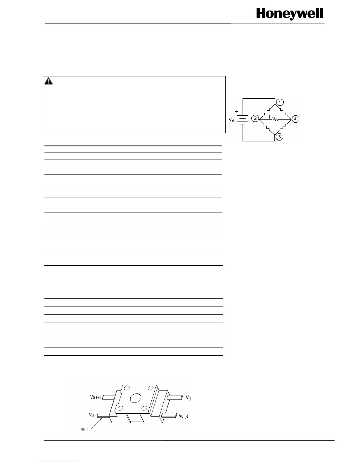
SENSOR PINOUT
500 grams
4,500 grams
grams
grams
mV
mV/gram
mV/gram
kV
EXCITATION SCHEMATIC
Excitation (Vdc) 5 Typ., 12 Max.
FS SERIES CIRCUIT
1. Circled numbers refer to sensor
terminals (pins).
Pin 1 = Supply V
Pin 2 = Output (+)
Pin 3 = Ground (-)
Pin 4 = Output (-)
2.The force sensor may be powered
by voltage or current. Maximum
supply voltage is not to exceed 12
volts. Maximum supply current is
not to exceed 1.6 mA. Power is
applied across Pin 1 and Pin 3.
3.The sensor output should be
measured as a differential voltage
across Pin 2 and Pin 4 (V
V
). The output is ratiometric to the
4
supply voltage. Shifts in supply
voltage will cause shifts in output.
Neither Pin 2 nor Pin 4 should be
tied to ground or voltage supply.
CLEANING
Proper cleaning fluids should be
selected, based on the type of
contaminants to be removed.
Honeywell recommends alcohols.
ISSUE 3
PK 80091
(+)
S
= V2 -
O
Sensing and Control © Honeywell 2003, All Rights Reserved
Page 2

FSL Series Force Sensor
MOUNTING DIMENSIONS (for reference only) mm/in
ISSUE 3 PK 80091
DESCRIPTION
Force Sensitivity Span Overforce
Catalog Range mV/V/gram mV grams
Listing (grams) Min. Typ. Max. Typ. Max.
FSL05N2C 500 .02 .024 .028 60 (@ 5 Vdc) 4,500
* Span: the algebraic difference between the output end points.
WARRANTY/REMEDY
Honeywell warrants goods of its manufacture as
being free of defective materials and faulty
workmanship. Contact your local sales office for
warranty information. If warranted goods are
returned to Honeywell during the period of coverage,
Honeywell will repair or replace without charge those
items it finds defective. The foregoing is Buyer’s
sole remedy and is in lieu of all other warranties,
expressed or implied, including those of
merchantability and fitness for a particular
purpose.
Specifications may change at any time without
notice. The information we supply is believed to be
accurate and reliable as of this printing. However, we
assume no responsibility for its use.
While we provide application assistance,
personally, through our literature and the Honeywell
web site, it is up to the customer to determine the
suitability of the product in the application.
For application assistance, current specifications,
pricing or name of the nearest Authorized Distributor,
contact a nearby sales office. Or call:
1-800-537-6945 USA
1-800-737-3360 Canada
1-815-235-6847 International
FAX
1-815-235-6545
INTERNET
www.honeywell.com/sensing
info.sc@honeywell.com
Sensing and Control
Honeywell
11 West Spring Street
Freeport, Illinois 61032
PK 80091-3-EN IL50 GLO 303 Printed in USA
www.honeywell.com/sensing
 Loading...