

Honeywell FSC-SM Installation Manual

FSC Safety Manager
Installation Guide
for use with the Honeywell FSC System
Releases 42x, 5xx and 600
FS20-500

.

Implementation
FSC Safety Manager
FSC Safety Manager
Installation Guide
for use with the Honeywell FSC System
Releases 42x, 5xx and 600
FS20-500
10/01

ii FSC Safety Manager Installation Guide 10/01
Copyright, Notices, and Trademarks
© Copyright 20 by Honeywell Inc.
Revision 0 – $SULO2, 201
While this information is presented in good faith and believed to be accurate,
Honeywell disclaims the implied warranties of merchantability and fitness for a
particular purpose and makes no express warranties except as may be stated in
its written agreement with and for its customer.
In no event is Honeywell liable to anyone for any indirect, special or consequential
damages. The information and specifications in this document are subject to
change without notice.
TotalPlant, TDC 3000 and Universal Control Network are U.S. registered
trademarks of Honeywell Inc.
FSC is a trademark of Honeywell Safety Management Systems.
Other brand or product names are trademarks of their respective owners.
Honeywell
Industrial Automation and Control
Automation College
2820 West Kelton Lane
Phoenix, AZ 85023
(602) 313-5669

10/01 FSC Safety Manager Installation Guide iii
About This Publication
This publication includes both general and detailed installation information for the various major
components of the FSC Safety Manager (FSC-SM) for use with the Honeywell FSC system
Releases 42x, 5xx and 600. Specifically included are:
• general installation instructions for the FSC Safety Manager (FSC-SM) system,
• detailed installation instructions for installing the FSC Safety Manager Module (FSC-SMM),
and
• general installation instructions for the FSC-SM system.
Site planning information is contained in the TotalPlant Solutions (TPS) System Site Planning
Manual, which is in the System Site Planning binder. After installation of the FSC-SM, the
checkout procedure can be found in the FSC Safety Manager Service Manual, which is in this
binder.
This publication supports TotalPlant® Solutions (TPS) System network Releases 53x and 62x.
TPS is the evolution of TDC 3000X.
All references in this manual to "FSC Safety Manager" or "FSC Safety
Manager Module" pertain only for use with the Honeywell FSC system.

iv FSC Safety Manager Installation Guide 10/01

10/01 FSC Safety Manager Installation Guide v
Table of Contents
SECTION 1 – FSC SAFETY MANAGER SYSTEM INSTALLATION................................................ 1
1.1 Section Overview .........................................................................................................1
1.2 Equipment Warehousing.............................................................................................. 2
1.3 Move Preparation......................................................................................................... 3
1.4 Unpacking and Placement .........................................................................................13
SECTION 2 – SYSTEM COMPONENT INSTALLATION ................................................................21
2.1 Section Overview .......................................................................................................21
2.2 Installation Considerations......................................................................................... 22
2.3 Cabinet Installation..................................................................................................... 23
2.4 Cabling Considerations.............................................................................................. 24
2.5 Cabling Installation.....................................................................................................29
2.6 System Power Connections....................................................................................... 34
2.7 System Ground Connections .....................................................................................36
2.8 UCN Connections....................................................................................................... 39
SECTION 3 – SYSTEM COMPONENT CONFIGURATION ............................................................ 43
3.1 Section Overview .......................................................................................................43
3.2 System Configuration Overview................................................................................. 44
3.3 Module Configuration................................................................................................. 45
SECTION 4 – CONFIGURATION..................................................................................................... 47
4.1 Section Overview .......................................................................................................47
4.2 Configuration at FSC User Station............................................................................. 48
4.3 Configuration at TPS Universal Station...................................................................... 49

vi FSC Safety Manager Installation Guide 10/01
Figures
Figure 1-1 Typical Electronics Room Layout.............................................................................. 3
Figure 1-2 Location and dimensions of the cabinet bolt-down holes .........................................6
Figure 1-3 FSC-SM cabinet with back access (FTA-T).............................................................. 7
Figure 1-4 FSC-SM cabinet with front access (FTA-T).............................................................. 8
Figure 1-5 FSC-SM cabinet with front and back access (FTA-T) .............................................. 9
Figure 1-6 FSC-SM cabinet with front access (FTA-E)............................................................10
Figure 1-7 FSC-SM cabinet with back access (FTA-E) ........................................................... 11
Figure 1-8 FSC-SM cabinet with front and back access (FTA-E)............................................ 12
Figure 1-8 Placement of equipment onto lumber.....................................................................14
Figure 1-9 Placement using a mobile lifter............................................................................... 16
Figure 1-10 Lifting equipment by mobile lifter of crane ..............................................................17
Figure 1-11 Lifting equipment by mobile lifter of crane — part 2................................................ 18
Figure 1-12 Eyebolt crane method............................................................................................. 19
Figure 2-1 FSC-SMM front plate .............................................................................................. 29
Figure 2-2 Redundant FSC-SM UCN cabling .......................................................................... 30
Figure 2-3 Typical routing layout of internal wiring between I/O modules and
FTA-T via SICs ....................................................................................................... 31
Figure 2-4 Typical routing layout of internal wiring between I/O modules and
FTA-E via SICs ....................................................................................................... 32
Figure 2-5 FSC Safety Manager cabinet power connections................................................... 34
Figure 2-6 Connection of the UCN........................................................................................... 40
Figure 4-1 US System Status display....................................................................................... 51
Figure 4-2 US Engineering Main Menu display........................................................................52
Figure 4-3 US NIM Build Type Select Menu............................................................................. 53
Figure 4-4 US UCN Node Configuration display...................................................................... 54
Figure 4-5 US Node-Specific Configuration display................................................................. 55
Figure 4-6 US Process Point Building display.......................................................................... 56

10/01 FSC Safety Manager Installation Guide vii
Tables
Table 1-1 Move preparation checklist .......................................................................................4
Table 1-2 Move preparation checklist – part 2.......................................................................... 5
Table 1-3 Important unpacking considerations .......................................................................13
Table 1-4 Fork lift considerations............................................................................................ 14
Table 1-5 Mobile lifter considerations ..................................................................................... 15
Table 1-6 Roller method considerations ................................................................................. 18
Table 2-1 FSC system installation checklist............................................................................22
Table 2-2 Raceway shielding.................................................................................................. 24
Table 2-3 IEEE 518 wiring classification definitions................................................................ 25
Table 2-4 Tray spacing............................................................................................................26
Table 2-5 Tray/conduit spacing............................................................................................... 26
Table 2-6 Conduit spacing ......................................................................................................27
Table 2-7 Cabling guidelines...................................................................................................28
Table 2-8 System grounding considerations........................................................................... 36
Table 4-1 Start-up and reconfiguration procedures ................................................................ 49
Table 4-2 UCN configuration................................................................................................... 50
Table 4-3 UCN node configuration.......................................................................................... 53
Table 4-4 FSC-SMM data point configuration procedure........................................................57

viii FSC Safety Manager Installation Guide 10/01
Acronyms
AC...........................................................................................................................Alternating Current
CP......................................................................................................................................Central Part
CPU...................................................................................................................Central Processor Unit
DBM..................................................................................................... Diagnostic and Battery Module
DC...................................................................................................................................Direct Current
DCS............................................................................................................ Distributed Control System
EMI..........................................................................................................Electromagnetic Interference
EPROM.......................................................................... Erasable Programmable Read-Only Memory
ESD.................................................................................................................. Electrostatic Discharge
FLD .............................................................................................................. Functional Logic Diagram
FSC............................................................................................................................ Fail Safe Control
FSC-DS.......................................................................................................FSC Development System
FSC-SM ...............................................................................................................FSC Safety Manager
FSC-SMM ...............................................................................................FSC Safety Manager Module
FTA ...........................................................................................................Field Termination Assembly
HM................................................................................................................................. History Module
I/O ..................................................................................................................................... Input/Output
IEEE.............................................................................Institute of Electrical and Electronic Engineers
LCN....................................................................................................................Local Control Network
LED.......................................................................................................................Light Emitting Diode
NCF.............................................................................................................Network Configuration File
NIM...............................................................................................................Network Interface Module
PLC..................................................................................................... Programmable Logic Controller
SIC........................................................................................................ System Interconnection Cable
SM................................................................................................................................Safety Manager
SMM................................................................................................................Safety Manager Module
TAC......................................................................................................... Technical Assistance Center
TPS.........................................................................................................................TotalPlant Solution
TTL...........................................................................................................Transistor - Transistor Logic
UCN ............................................................................................................ Universal Control Network
US..............................................................................................................................Universal Station
VBD......................................................................................................................... Vertical Bus Driver
WD........................................................................................................................................Watchdog

10/01 FSC Safety Manager Installation Guide ix
References
For FSC-SM documentation:
Publication
Title
Publication
Number
Binder
Title
Binder
Number
FSC Safety Manager Installation
Guide
FS20-500 Implementation
FSC Safety Manager
TPS 3076
FSC Safety Manager Implementation
Guidelines
FS11-500 Implementation
FSC Safety Manager
TPS 3076
FSC Safety Manager Control
Functions
FS09-500 Implementation
FSC Safety Manager
TPS 3076
FSC Safety Manager Parameter
Reference Dictionary
FS09-550 Implementation
FSC Safety Manager
TPS 3076
FSC Safety Manager Configuration
Forms
FS88-500 Implementation
FSC Safety Manager
TPS 3076
FSC Safety Manager Service Manual FS13-500 Implementation
FSC Safety Manager
TPS 3076
For FSC documentation:
Publication
Title
Publication
Number
FSC Safety Manual PM.MAN.8047
FSC Hardware Manual PM.MAN.8048
FSC Software Manual PM.MAN.8025

x FSC Safety Manager Installation Guide 10/01

10/01 FSC Safety Manager Installation Guide 1
Section 1 – FSC Safety Manager System Installation
1.1 Section Overview
About this section
This section provides general installation information for the FSC Safety
Manager (FSC-SM) system. Topics included in this section are:
Subsection Topic See Page
1.1 Section Overview........................................................................................ 1
1.2 Equipment Warehousing............................................................................ 2
1.3 Move Preparation........................................................................................ 3
1.4 Unpacking and Placement........................................................................ 13
Tools and test
equipment
The following equipment is necessary for installation of the FSC Safety
Manager:
• Mobile lifter/lift truck — refer to Subsection 1.4 (Unpacking and
Placement),
• Carrier band MAP tester — refer to Subsection 2.2 (Installation
Considerations),
• Hand tools and multimeter, as in a typical electrician's tool kit,
• UCN Connector Torque Wrench Kit (part number: 4605459),
• Set of SAE (inch) "crow's foot" wrenches for the above torque wrench,
• ESD kit (Honeywell part number 30185-H).
ATTENTION
Installation of the FSC Safety Manager may only be
carried out by qualified and authorized personnel. Failure to comply with
the regulations and recommendations contained in this document may
cause severe damage to the equipment or serious injury to people.
REFERENCE — For detailed information regarding
• site planning and installation, refer to SM02-550 TPS System Site
Planning Manual in Binder TPS 3020-1 System Site Planning-1.
• post-installation checkout procedures, refer to the FSC Safety Manager
Service Manual in this binder.

2 FSC Safety Manager Installation Guide 10/01
1.2 Equipment Warehousing
Factory packing
For shipment, the FSC Safety Manager is packed with desiccant packages,
wrapped in a moisture barrier and optionally enclosed for shipment as
required by the user.
Transit/warehousing
specifications
The FSC Safety Manager can be shipped by a variety of means, but any
trucking should be done by enclosed air-ride vans. The equipment is
usually trucked on the final leg of the journey to the user warehouse or
site. There it is stored off the ground on a solid piece or combination of
lumber pieces (minimum height 10 cm / 4 in) and indoors until needed for
installation. During the whole process, the environment must be
monitored and corrected if the following equipment transit/storage ratings
are exceeded:
• Temperature range: –20°C to +70°C (–4°F to +158°F)
• Relative humidity: 5% to 95%, non-condensing
• Vibration: 1 G, frequency 10-150 Hz (IEC 68-2-6)
• Shock: 15 G for 11 ms (IEC 68-2-27)
A
TTENTION
In order to minimize exposure to humidity, keep the
factory wrapping intact during storage and transit. If it is necessary to
unseal the equipment for customs or receiving, add more desiccant and
reseal the package.
10/01 FSC Safety Manager Installation Guide 3
1.3 Move Preparation
Background
Several basic points need to be kept in mind when planning the movement
and unpacking of FSC Safety Manager cabinets. They include the
following:
• A single FSC Safety Manager cabinet is nominally 80 x 80 x 200 cm
(31½ x 32½ x 78¾ inches),
• Lifting eye bolts, which are removable, add about 5 cm (2 inches) to the
height, and
• Weight varies with options and can go as high as 385 kg (850 lb) per
cabinet.
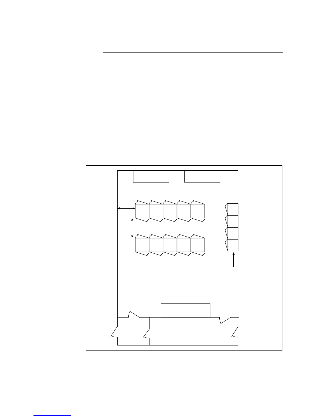
As illustrated in Figure 1-1, a typical factory-assembled complex uses up
to four such cabinets bolted together.
Figure 1-1 – Typical Electronics Room Layout
0-30 V
Terminal Panel
30-250 V
Terminal Panel
4 ft (1.25 m)
Min. Typical
Note:
These cabinets
are stand ar d width,
but are 21.75 inches
(55 cm) deep.
Control Cabine ts
Control Cabine ts
54 in (1.37 m)
(Reference)
Single-Access Control Cabinets
Expansion Area
Change House,
Lunchroom, Etc.
Power Distribution
Panel
Utility Room,
Maintenance
Equipment
Continued on next page

4 FSC Safety Manager Installation Guide 10/01
1.3 Move Preparation, Continued
Checklist
Table 1-1 provides a checklist to be used when planning the movement of
FSC Safety Manager cabinets.
Table 1-1 – Move preparation checklist
Check Action Notes
1
Travel Route Chart the equipment's route of travel regarding:
• loading doors — height and location,
• elevators — size, capacity, and availability,
• aisles — number, size, and layout,
• doorways — number and size,
• hallways — size, restrictions, and bends,
• stairs and ramps — may require some type of
lifting, and
• rigging of equipment — if needed.
2
Space Is there enough space to hold the equipment?
3
Floor Loading Will the floor in all areas be strong enough?
4
Power Distribution Check for proper transformer sizes, distribution
panels and sufficient outlets for support, test and
maintenance equipment.
5
Grounding Be sure that proper grounds are available.
6
Conduits and
Cable Trays
Make sure that conduits and cable trays are
large enough and the proper type to
accommodate all of the required cables.
7
Environment Are lighting and other environmental
requirements adequate?
8
Security Provide security clearances for the installation
crew if it is not composed of regular employees.
9
Responsibilities Are all responsibilities clearly defined and
understood?
10
Communications At minimum, three conveniently located
telephones are needed for:
• Honeywell Technical Assistance Center (TAC)
data terminal,
• Honeywell TAC voice, and
• Operator Emergency.
For additional information regarding actions described in the
Move Preparation Checklist, refer to SM02-550 — TPS System Site
Planning Manual in the Binder TPS 3020-1 System Site Planning-1.

10/01 FSC Safety Manager Installation Guide 5
1.3 Move Preparation, Continued
Preparation
Table 1-2 provides a checklist to be used when preparing the electronics
room for the FSC Safety Manager cabinets.
Table 1-2 – Move preparation checklist – part 2
Check Action Notes
1
Static Electricity Reduce the ESD-borne failures by:
• stripping the floors of any wax to prevent
static charge buildup,
• using anti-static spray on floors, furniture and
fabric in the work area, and
• placing a sign on or near the equipment that
states circuit boards are not to be handled
without wearing a ground strap.
2
Tack Rugs Placed at all entrances, tack rugs catch dust, grit
and abrasives from other areas.
3
Fire Prevention Consult with the local fire prevention authority to
select fire extinguishers suitable for electrical
fires.
4
Room Layout Prepare an electronics room layout diagram for
cabinet placement.
• Refer to Figure 1-1.
5
Cabinet
Bolt-Down
If this FSC Safety Manager cabinet is to be
bolted down, pre-drill holes in the floor.
A
TTENTION
Refer to Figure 1-2 for
placement and dimensions of the bolt-down
holes.
Continued on next page
6 FSC Safety Manager Installation Guide 10/01
1.3 Move Preparation, Continued
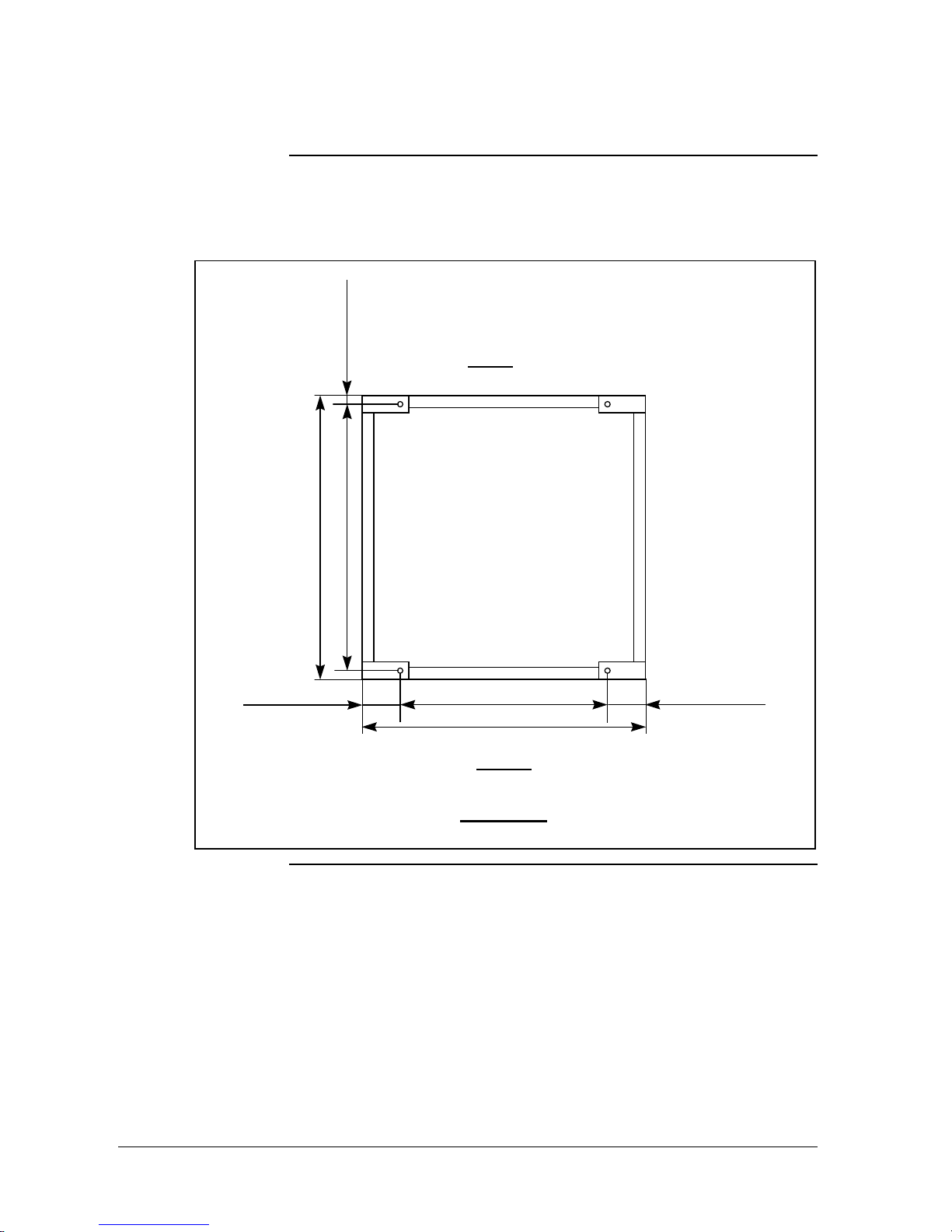
Bolt-down holes
Figure 1-2 provides the exact locations and dimensions of the cabinet
bolt-down holes.
Figure 1-2 – Location and dimensions of the cabinet bolt-down holes
600 mm (23.62")
800 mm (31.50")
100 mm (3.94")
750 mm (29.53")
100 mm (3.94")
25 mm (0.98")
700 mm (27.57")
REAR
FRONT
Bolt-down hole
diameter:
14 mm (0.55")
TOP VIEW
Continued on next page
10/01 FSC Safety Manager Installation Guide 7
1.3 Move Preparation, Continued
Cabinet entry
The process signal cables can enter the FSC Safety Manager cabinet
through the top or bottom of the cabinet. The FSC-SM cabinet is prepared
for field termination assembly to interface boards (FTA-E) or terminals
(FTA-T). These interface boards or terminals may be located in the
FSC-SM cabinet or in cross-wiring cabinets next to the FSC-SM cabinet.
Figures 1-3 through 1-8 illustrate the placement and dimensions for
process wiring for FTAs located in the FSC-SM cabinet.
The FSC-SM cabinet is also prepared for top or bottom entry as per user
specification. For bottom entry, sliding floor plates are provided which can
be adjusted to provide entry slots. For top entry, one sliding plate is
provided which can be adjusted to provide entry slots. For top or bottom
entry, the cables should be clamped firmly to the cabinet. The clamping
devices should be able to withstand a 45 kg (100 lb) pull. This prevents
damage inside the cabinet when pulling on cables outside the cabinet.
The FSC-SM cabinet includes a cable clamp rail at the bottom or at the
top.
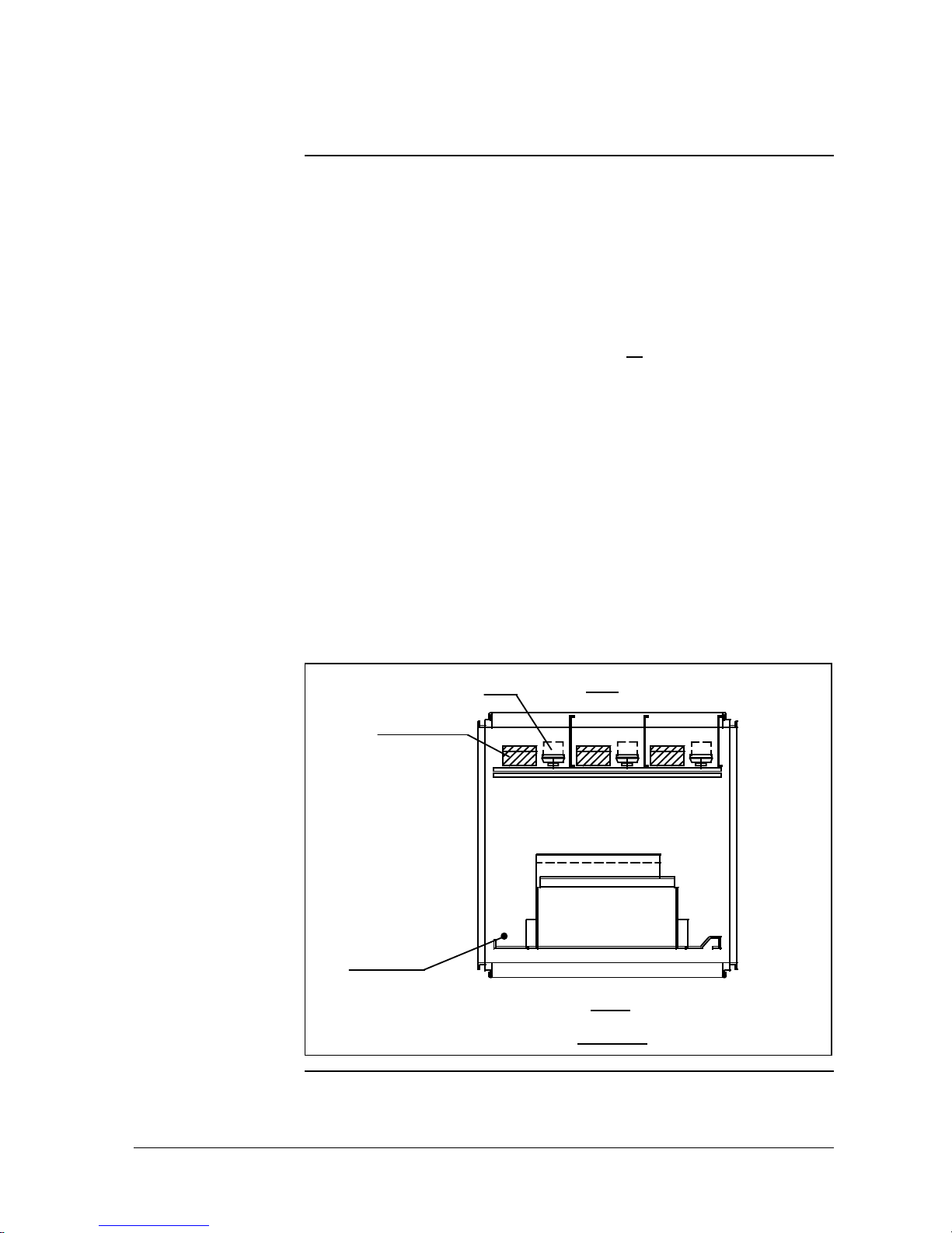
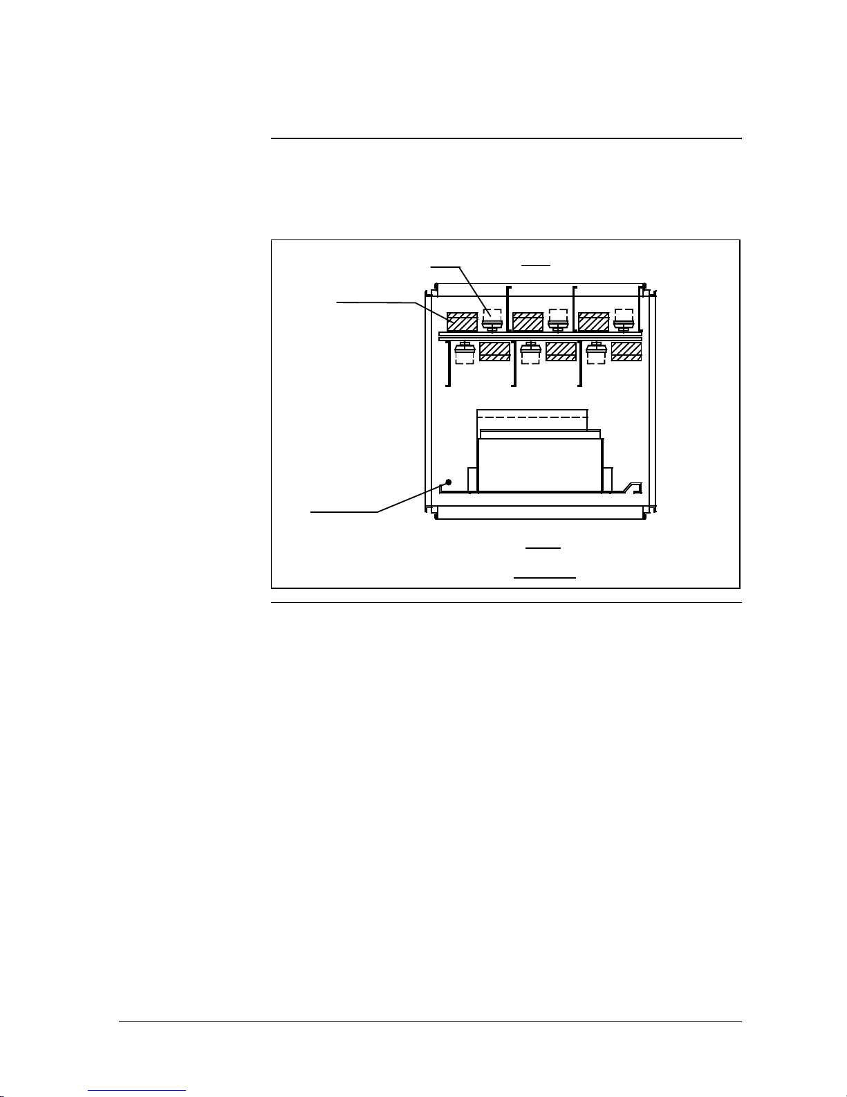
Figure 1-3 illustrates an FSC-SM cabinet bottom configured for back
access of the I/O field cables with FTA-T.
Figure 1-3 – FSC-SM cabinet with back access (FTA-T)
FSC I/O mounting rack
FRONT
TOP VIE W
Turning point
swing frame
REARFTA-T
Field cable duct
Continued on next page
8 FSC Safety Manager Installation Guide 10/01
1.3 Move Preparation, Continued
Cabinet entry,
continued
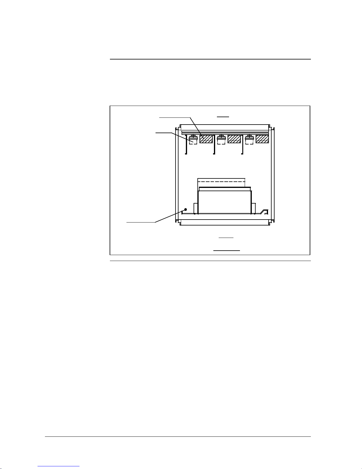
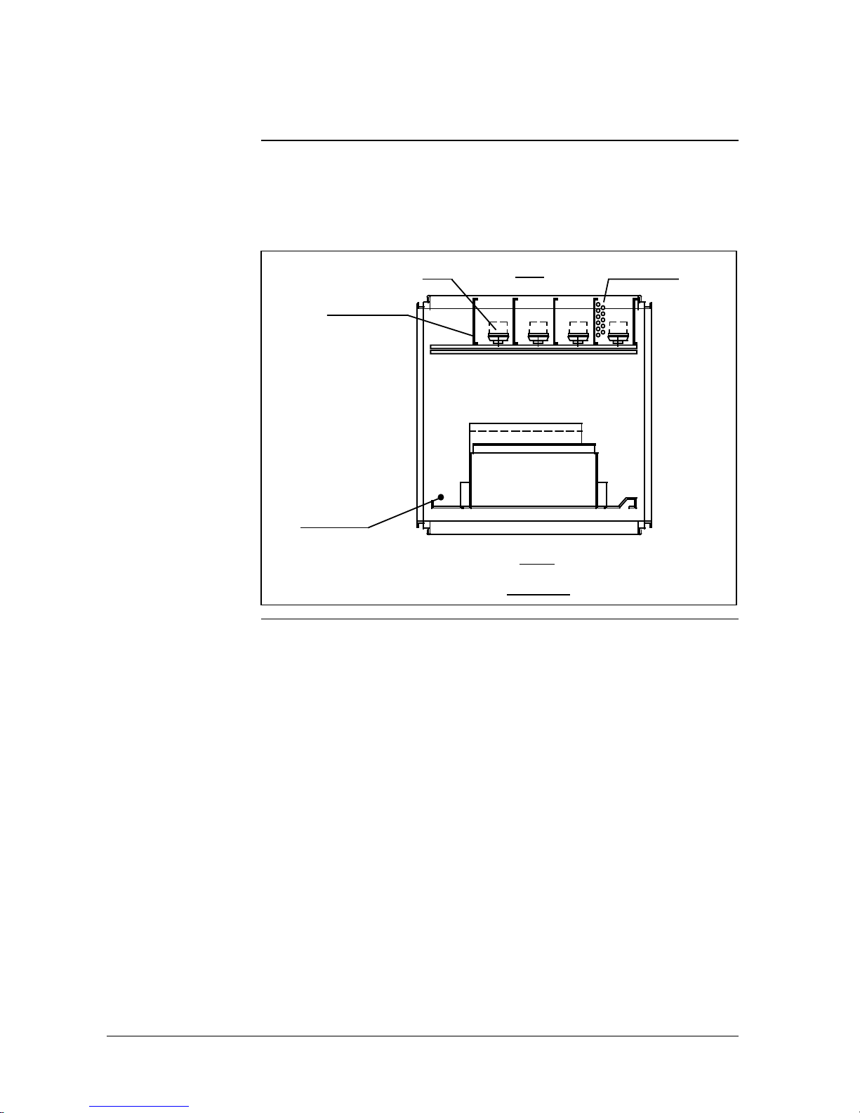
Figure 1-4 illustrates an FSC Safety Manager cabinet bottom configured
for front access of the I/O field cables with FTA-T.
Figure 1-4 – FSC-SM cabinet with front access (FTA-T)
FSC I/O mounting rack
Turning point
swing frame
FTA-T
Field cable duct
REAR
FRONT
TOP VIE W
Continued on next page
10/01 FSC Safety Manager Installation Guide 9
1.3 Move Preparation, Continued
Cabinet entry,
continued
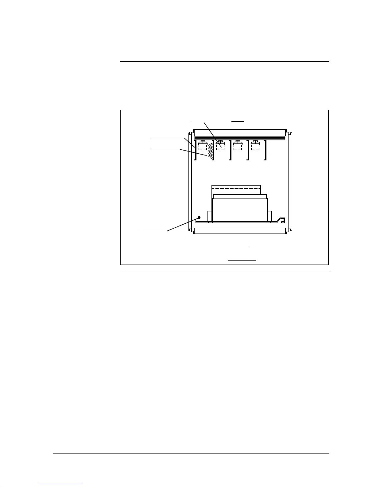
Figure 1-5 illustrates an FSC Safety Manager cabinet bottom configured
for front and back access of the I/O field cables with FTA-T.
Figure 1-5 – FSC-SM cabinet with front and back access (FTA-T)
FSC I/O mounting rack
Turning point
swing frame
FTA-T
Field cable duct
REAR
FRONT
TOP VIE W
Continued on next page
10 FSC Safety Manager Installation Guide 10/01
1.3 Move Preparation, Continued
Cabinet entry,
continued
Figure 1-6 illustrates an FSC Safety Manager cabinet bottom configured
for front access of the system cables with FTA-E.
Figure 1-6 – FSC-SM cabinet with front access (FTA-E)
FSC I/O mounting rack
FRONT
TOP VIE W
Turning point
swing frame
REARFTA-E
Field cable tray
System cables
Continued on next page
10/01 FSC Safety Manager Installation Guide 11
1.3 Move Preparation, Continued
Cabinet entry,
continued
Figure 1-7 illustrates an FSC Safety Manager cabinet bottom configured
for back access of the system cables with FTA-E.
Figure 1-7 – FSC-SM cabinet with back access (FTA-E)
FSC I/O mounting rack
FRONT
TOP VIE W
Turning point
swing frame
REARFTA-E
Field cable tray
System cables
Continued on next page
 Loading...