

Page 1
D22
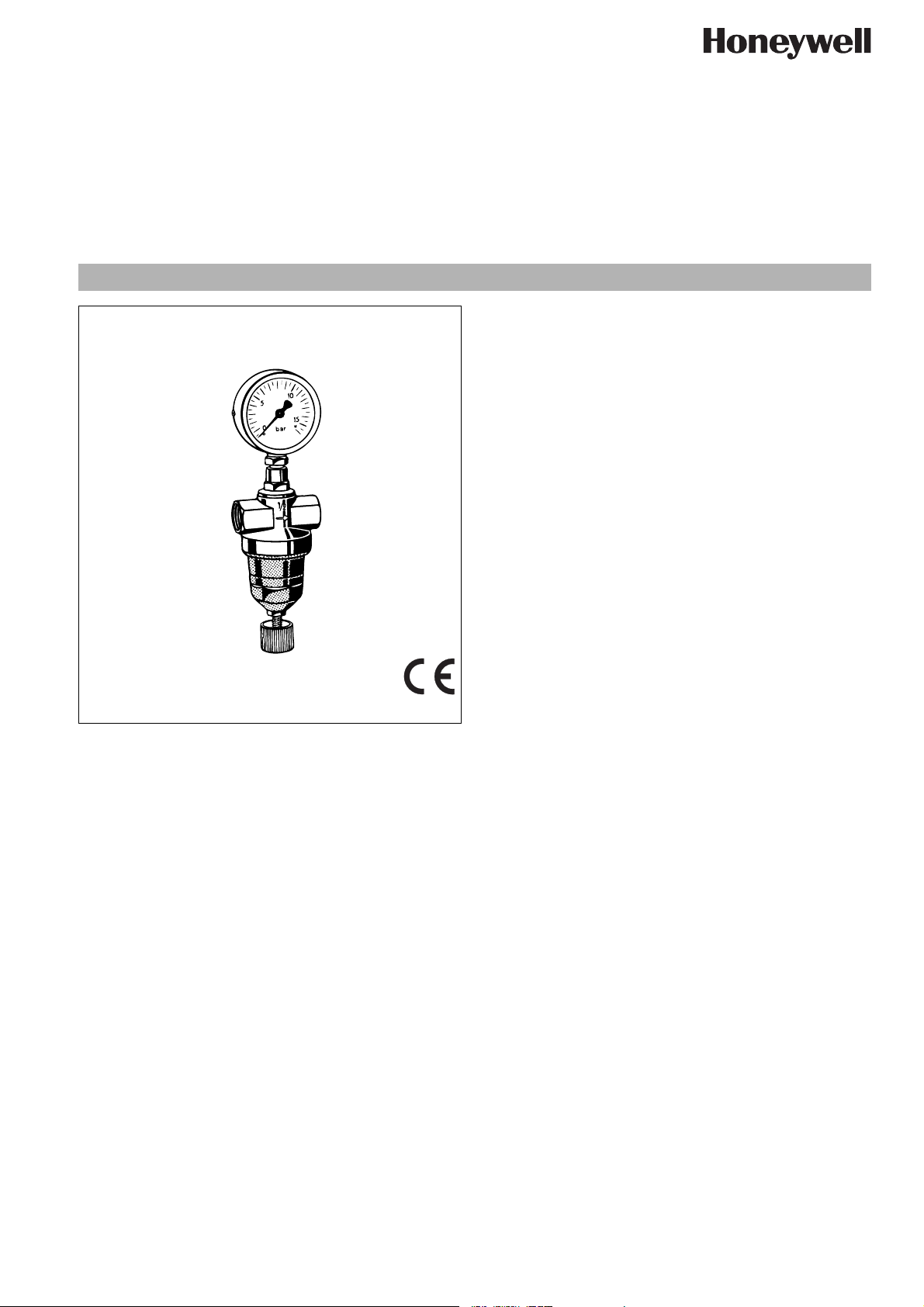
Pressure reducing valve with piston balanced seat
Standard pattern for compressed air
Product specification sheet
Application
Pressure reducing valves of this type protect installations against
excessive pressure from the supply. They can be used for industrial or commercial applications within the range of their specification.
Because pressure reducing valves are subject to wear, they
cannot be used as the only means of protection and if the downstream system needs to be protected against excessive pressure
to prevent leakage, then a suitable safety valve must be fitted.
Special Features
• Screw with knob for setting pressure
• The adjustment spring is not in contact with the medium
• Compact construction
• Internal threaded connection
• Light weight
• Short installed length
• Inlet pressure balancing - fluctuating inlet pressure does not
influence outlet pressure
• Certified to Pressure Equipment Directive 97/23/EC, Reference No. CE 0035
• Reliable and proven
Construction
The pressure reducing valve comprises:
•Housing
•Valve piston
• Piston guide with G
• Diaphragm
• Adjustment spring
• Spring bonnet with adjuster
• Pressure gauge not included (see accessories)
Materials
• Brass housing
• Brass valve piston
• Brass piston guide
• High-quality synthetic material spring bonnet
• Spring steel adjustment spring
• NBR sealing washer
• NBR Diaphragm
EN0H-1011GE23 R1109 • Subject to change
• NBR O-rings
1
/4" pressure gauge connection
Range of Application
Medium Compressed air*, non-toxic and non-
flammable gases
Inlet pressure max. 40 bar
Outlet pressure 1,0 - 10,0 bar
Technical Data
Operating temperature max. 70°C
Nominal pressure PN40
Minimum pressure drop 1.0 bar
Connection size
*
As part of an installation being approved according to PED requirements, this
product must also be certified.
1
/4" - 2"
www.honeywell.com 55
Page 2
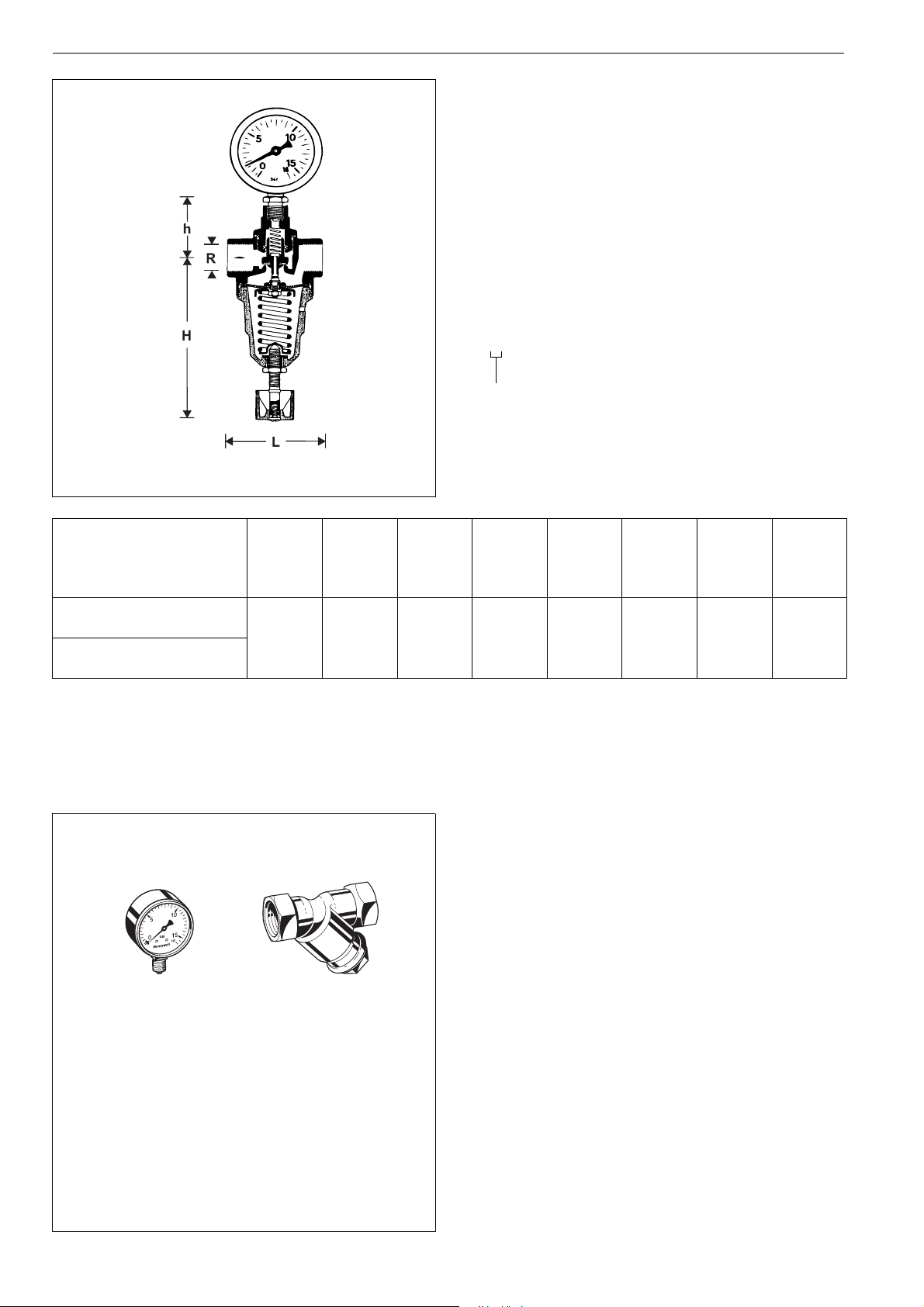
D22 Pressure reducing valve with piston balanced seat
Method of Operation
Spring loaded pressure reducing valves operate by means of a
force equalising system. The force of a diaphragm operates
against the force of an adjustment spring. If the outlet pressure
and therefore diaphragm force fall because water is drawn, the
then greater force of the spring causes the valve to open. The
outlet pressure then increases until the forces between the
diaphragm and the spring are equal again.
The inlet pressure has no influence in either opening or closing of
the valve. Because of this, inlet pressure fluctuation does not
influence the outlet pressure, thus providing inlet pressure balancing.
Options
D22-... A = Standard pattern
Special Versions available on request
Connection size
Connection size R
Nominal size
DN8 10152025324050
1
/4"
3
/8"
1
/2"
3
/4"1"1
1
/4"1
1
/2"2"
diameter
Weight approx. kg 0,3 0,3 0,45 0,6 1,35 1,8 2,9 3,8
Dimensions mm
L5050658095105115130
h 90 90 105 105 150 160 200 210
D3434364257577272
Accessories
FY30 Strainer
With double mesh strainer, brass housing
A = Mesh size approx. 0.35 mm
M38K Pressure gauge
Housing diameter 50 mm, below connection thread
G1/4". Ranges: 0 - 4, 0 - 10, 0 - 16 or 0 - 25 bar.
Please indicate upper value of pressure range when
M38K
FY30
ordering
56 www.honeywell.com
EN0H-1011GE23 R1109 • Subject to change
Page 3

Installation Example
D22 Pressure reducing valve with piston balanced seat
10
5
15
bar
0
16
Connection size R
1
/4"3/8"1/2"3/4"1"11/4"11/2"2"
DN8 10152025324050
W* mm 45 45 50 50 55 60 60 70
* Minimum distance from wall to centre line of pipework
Installation Guidelines
• Install in horizontal pipework with spring hood directed downwards.
• Install shutoff valves
• The installation location should be protected against frost
and be easily accessible
o Pressure gauge can be read off easily
o Simplified maintenance and cleaning
• Install downstream of the filter or strainer
Typical Applications
Pressure reducing valves of this type are suitable for household,
industrial and commercial applications within the range of their
specifications.
Pressure reducing valves should be installed:
• If the static pressure exceeds the maximum permissible value
for the system
• If pressure fluctuations in the downstream system must be
avoided
o This position ensures optimum protection for the pressure
reducing valve against dirt
• Provide a straight section of pipework of at least five times the
nominal valve size after the pressure reducing valve (in accordance with DIN 1988, Part 5)
EN0H-1011GE23 R1109 • Subject to change
www.honeywell.com 57
Page 4

D22 Pressure reducing valve with piston balanced seat
1
Spare Parts
Pressure Reducing Valve D22, from 1968 onwards
No. Description Dimension Part No.
1 Valve cone complete1/4"
for D22
+ 3
/8" 0903223
1
/2" 0903224
3
/4" 0903225
1" 0903226
1
1
/4" 0903227
1
1
/2" 0903228
2" 0903229
1
2 Diaphragm for D22
3 Spring bonnet
complete for D22
+ 3
/4"
/8" 2202500
1
+ 3
/2"
/4" 2202700
+ 11
1"
/4" 2203300
1
1
/2" + 2" 2204100
1
+ 3
/4"
/8" 0900272
1
+ 3
/2"
/4" 0900273
+ 11
1"
/4" 0900274
1
1
/2" + 2" 0900275
2
3
Automation and Control Solutions
Honeywell GmbH
Hardhofweg
D-74821 Mosbach
Phone: (49) 6261 810
Fax: (49) 6261 81309
http://europe.hbc.honeywell.com
www.honeywell.com
Manufactured for and on behalf of the
Environmental and Combustion Controls Division
of Honeywell Technologies Sàrl, Rolle, Z.A. La
Pièce 16, Switzerland by its Authorised Representative Honeywell GmbH
EN0H-1011GE23 R1109
Subject to change without notice
© 2009 Honeywell GmbH
 Loading...