

Page 1
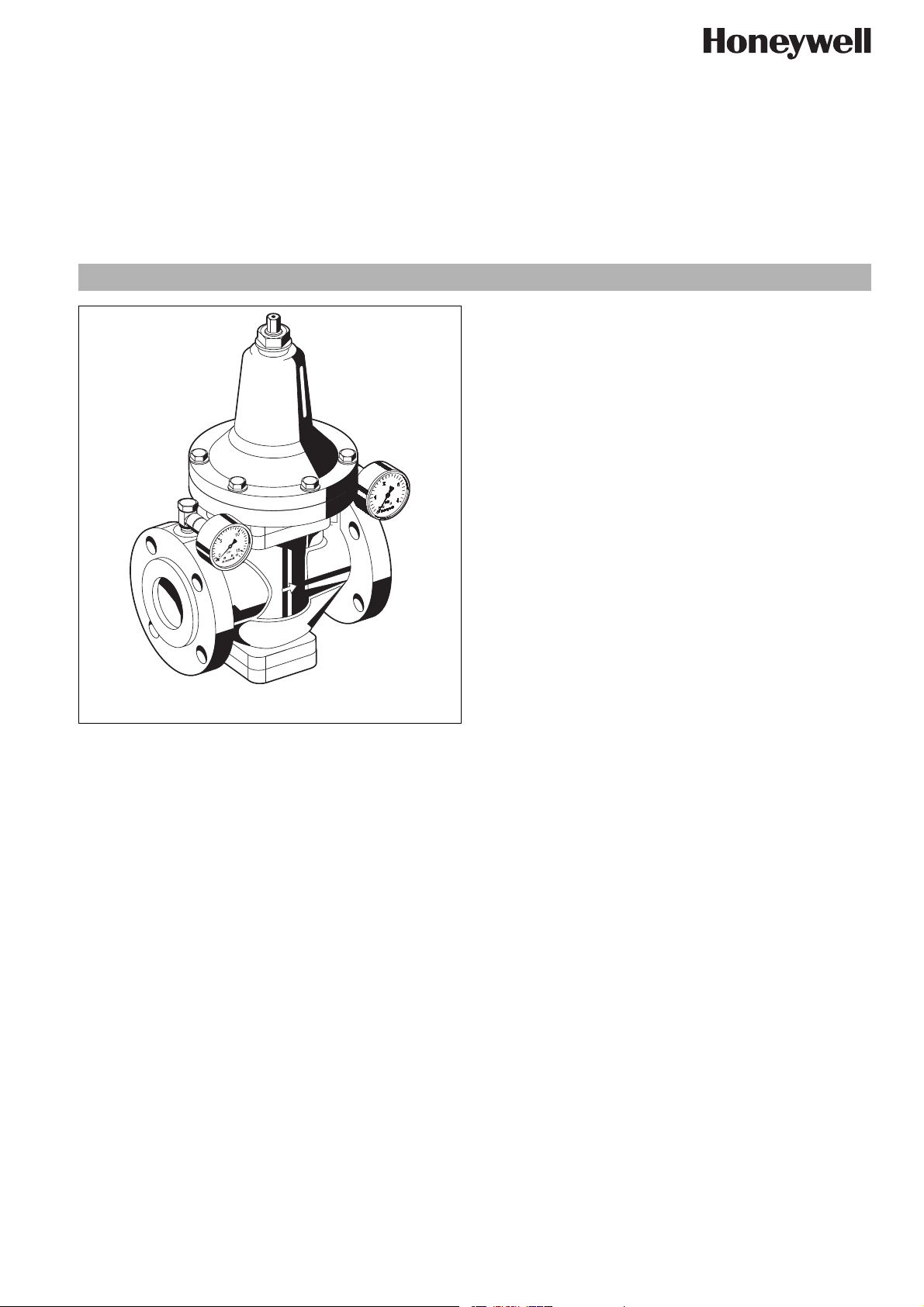
Pressure reducing valve with balanced seat
Construction
The pressure reducing valve comprises:
• Housing with PN16 flanges per ISO7005-2, EN1092-2
• Spring bonnet with adjustment screw
• Adjustment spring
• Valve system complete with diaphragm
• Pressure gauge
Materials
• Grey cast iron housing
• Cast iron spring bonnet
• Bronze valve seat
• Bronze piston guide
• Cone up to DN150: brass, DN200: steal
• Spring steel adjustment spring
•EPDM diaphragm
• NBR seal collar
• NBR seals
EN0H-1008GE23 R1109 • Subject to change
• Stainless steel screws and nuts
D15NP
Low pressure pattern
Product specification sheet
Application
Pressure reducing valves of this type protect installations against
excessive pressure from the supply. They can be used for industrial or commercial applications within the range of their specification.
By installing a pressure reducing valve, pressurisation damage is
avoided and water consumption is reduced.
The set pressure is also maintained constant, even when there is
wide inlet pressure fluctuation.
Reduction of the operating pressure and maintaining it at a
constant level minimizes flow noise in the installation.
Special Features
• Non-rising stem for setting outlet pressure and position indicator on spring bonnet (except for DN200)
• The adjustment spring is not in contact with the potable water
• With inlet and outlet pressure gauge (DN80-DN150) or with
outlet pressure gauge (DN50, DN65, DN200)
• Inlet pressure balancing - fluctuating inlet pressure does not
influence outlet pressure
• Powder coated inside and outside - Powder used is physiologically and toxicologically safe
• Reliable and proven
Range of Application
Medium Water, compressed air* and nitrogen* in
consideration of valid standards (e.g. DIN
EN 12502)
Inlet pressure max. 16 bar
Outlet pressure 0.2 - 2 bar
Technical Data
Operating temperature
Nominal pressure PN16
Minimum pressure
drop
Diaphragm pressure
loading
Nominal size DN50 - DN200
*
As part of an installation being approved according to PED requirements, this
product must also be certified.
max. 70°C
0.5 bar
max. 3.0 bar
www.honeywell.com 47
Page 2
D15NP Pressure reducing valve with balanced seat
Method of Operation
Spring loaded pressure reducing valves operate by means of a
force equalising system. The force of a diaphragm operates
against the force of an adjustment spring. If the outlet pressure
and therefore diaphragm force fall because water is drawn, the
then greater force of the spring causes the valve to open. The
outlet pressure then increases until the forces between the
diaphragm and the spring are equal again.
The inlet pressure has no influence in either opening or closing of
the valve. Because of this, inlet pressure fluctuation does not
influence the outlet pressure, thus providing inlet pressure balancing.
Options
D15NP-... A = With PN 16 flanged connections to DIN 2533
and BS 4504, cast iron housing
Special Versions available on request
Connection size
Connection size DN 50 65 80 100 125 150 200
Weight kg 21 37 54 87.5 135 196 580
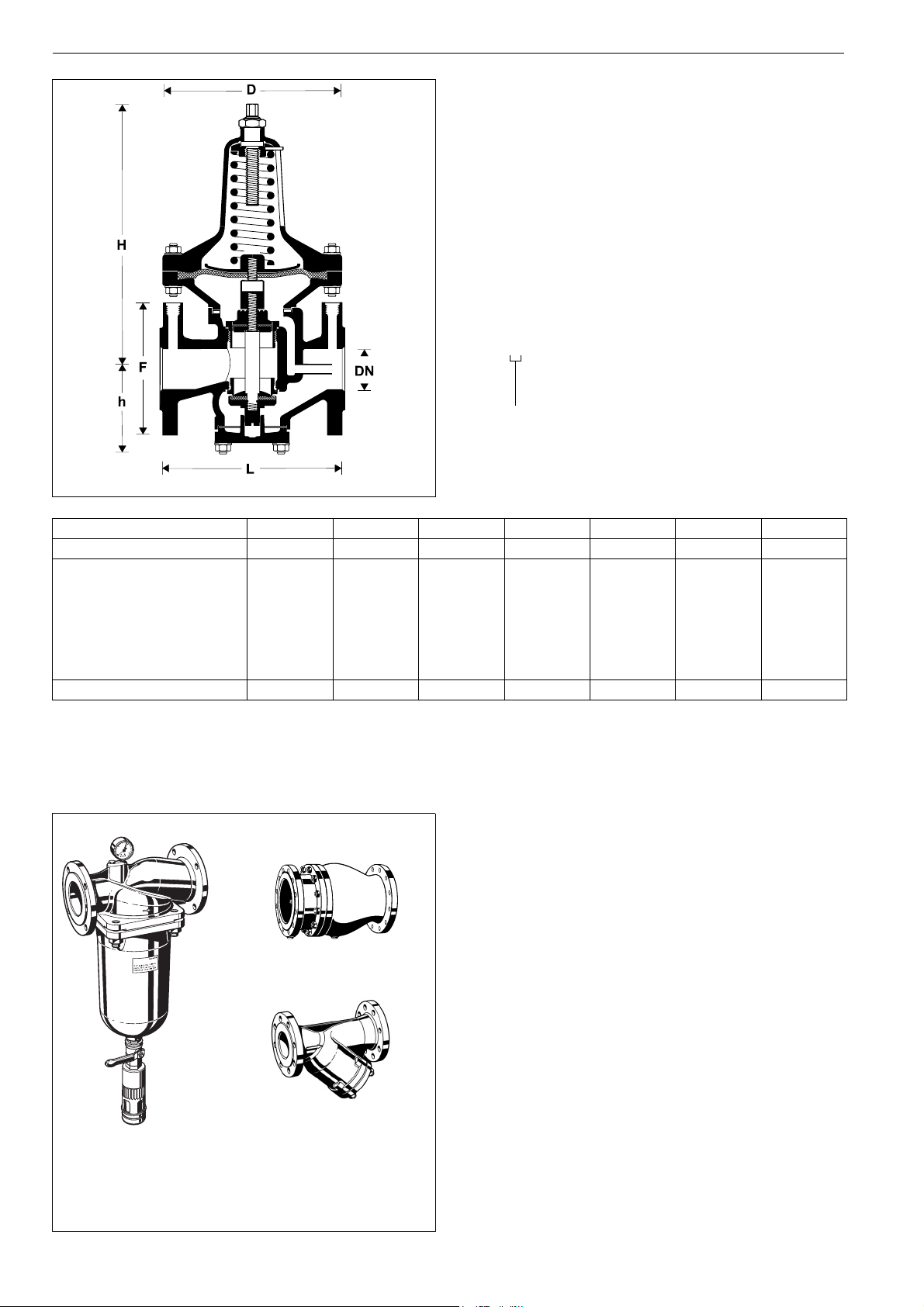
Dimensions mm
L 230 290 310 350 400 480 600
approx. H 300 370 415 515 575 670 1430
h 106 126 154 183 210 248 305
D 192 260 295 410 440 510 780
F 165 185 200 220 250 285 340
-value m3/h 28 47 70 110 180 250 380
k
vs
Accessories
5
r
15
ba
0
16
RV283P Check valve
Grey cast iron housing, powder coated inside and
outside. DIN/DVGW tested in compulsory test sizes
DN 65, DN 80 and DN 100
FY69P Strainer
RV283P
With double mesh, grey cast iron housing, powder
coated inside and outside.
A = Mesh size approximately 0.5 mm
F76S-F
48 www.honeywell.com
FY69P
F76S-F Reverse-rinsing filter
Red bronze housing and filter bowl. Available in sizes
DN 65 to DN 100, with filter mesh sizes 100 µm
or 200 µm
EN0H-1008GE23 R1109 • Subject to change
Page 3

Installation Example
Connection size DN 50 65 80 100 125 150 200
W* mm 115 150 170 225 240 275 410
* Minimum distance from wall to centre line of pipework
D15NP Pressure reducing valve with balanced seat
Installation Guidelines
• Install in horizontal pipework with spring bonnet directed
upwards
• Install shutoff valves
• The installation location should be protected against frost
and be easily accessible
o Pressure gauge can be read off easily
o Simplified maintenance and cleaning
• Install downstream of the filter or strainer
o This position ensures optimum protection for the pressure
reducing valve against dirt
• Provide a straight section of pipework of at least five times the
nominal valve size after the pressure reducing valve (in accordance with DIN 1988, Part 5)
Flow Diagram
Typical Applications
Pressure reducing valves of this type are suitable for multi dwelling buildings, industrial and commercial applications within the
range of their specifications.
Pressure reducing valves should be installed:
• If the static pressure exceeds the maximum permissible value
for the system
• If several pressure zones are required when a pressurisation
system is used (pressure reducers on each storey of a building)
• If pressure fluctuations in the downstream system must be
avoided
• To achieve constant inlet and outlet pressures on pumped
pressure boosting systems
• To reduce the water consumption
EN0H-1008GE23 R1109 • Subject to change
www.honeywell.com 49
Page 4

D15NP Pressure reducing valve with balanced seat
DN50 - DN150
1
6
4
2
2
2
2
3
Spare Parts
Pressure Reducing Valve D15NP, from 2003 onwards
No. Description Dimension Part No.
1 Diaphragm for D15NPDN 50 5708000
DN 65 5708100
DN 80 5708200
DN 100 5708300
DN 125 5708400
DN 150 5708500
DN 200 5708600
2 Set of seals DN 50 0901353
DN 65 0901354
DN 80 0901355
DN 100 0901356
DN 125 0901357
DN 150 0901358
DN 200 0901359
3 Guide bush with seal DN 50 0900255
DN 65 0900256
DN 80 0900257
DN 100 0900258
DN 125 0900259
DN 150 0900260
DN 200 0900261
DN200
1
2
4 Seat bush with seal DN 50 0900247
DN 65 0900248
DN 80 0900249
DN 100 0900250
DN 125 0900251
DN 150 0900252
DN 200 0900253
6
5
5 Pressure gauge M07M-A16
Ranges 0 - 16 bar
6 Pressure gauge M07M-A4
Ranges 0 - 4 bar
4
2
2
3
Automation and Control Solutions
Honeywell GmbH
Hardhofweg
D-74821 Mosbach
Phone: (49) 6261 810
Fax: (49) 6261 81309
http://europe.hbc.honeywell.com
www.honeywell.com
2
Manufactured for and on behalf of the
Environmental and Combustion Controls Division
of Honeywell Technologies Sàrl, Rolle, Z.A. La
Pièce 16, Switzerland by its Authorised Representative Honeywell GmbH
EN0H-1008GE23 R1109
Subject to change without notice
© 2009 Honeywell GmbH
 Loading...