

Page 1
D1,D2, and D3 Models
WARNING
CAUTION
WARNING
VERTICAL AND HORIZONTAL MOUNT
ELECTRICAL GUIDELINES
Electrical and/or pneumatic connections to damper actuators
should be made in accordance with wiring and piping
diagrams developed in compliance with applicable codes,
ordinances and regulations.
Verify power requirements.
Verify power requirements before wiring actuator.
Honeywell is not responsible for any damage to, or
failure of the unit caused by incorrect field wiring.
OWNER'S GUIDE
RECEIVING AND HANDLING
Upon receiving dampers, check for both obvious and hidden
damage. If damage is found, record all necessary information
on the bill of lading and file a claim with the final carrier. Check
to be sure that all parts of the shipment, including
accessories, are accounted for.
Dampers must be kept dry and clean. Indoor storage and
protection from dirt, dust and the weather is highly
recommended. Do not store at temperatures in excess of
100°F (37ºC).
Can cause severe injury, death, or property
damage.
Improper installation, adjustment, alteration, service or
maintenance can cause property damage, injury or
death. Read the installation, operating, and
maintenance instructions thoroughly before installing
or servicing this equipment.
Electrical Shock Hazard.
Electrical input may be needed for this equipment.
This work should be performed by a qualified
electrician.
Pre-Installation Guidelines
The basic intent of a proper installation is to secure the
volume control damper into the opening in such a manner as
to prevent distortion and disruption of damper operation. The
following items will aid in completing the damper installation in
a timely and effective manner.
1. Check the schedules for proper damper locations within
the building. Visually inspect the damper for damage.
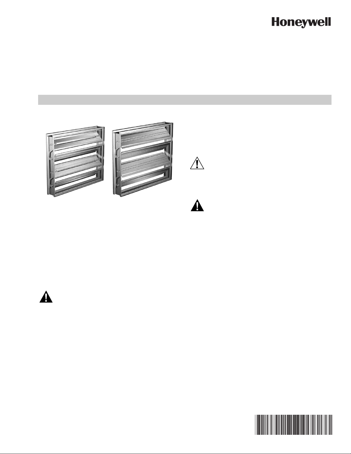
2. Lift or handle damper using sleeve or frame. Do not lift
damper using blades, linkage, actuators, or
jackshafting. When handling multiple sections
assemblies, use sufficient support to evenly lift at each
section mullion (see Fig. 1). Do not drag, step on, apply
excessive bending, twisting, or racking.
38-00031-01
Page 2
D1,D2, AND D3 MODELS
M35708
SPREADER
BAR
ATTACHMENTS
MULTI SECTION DAMPERS
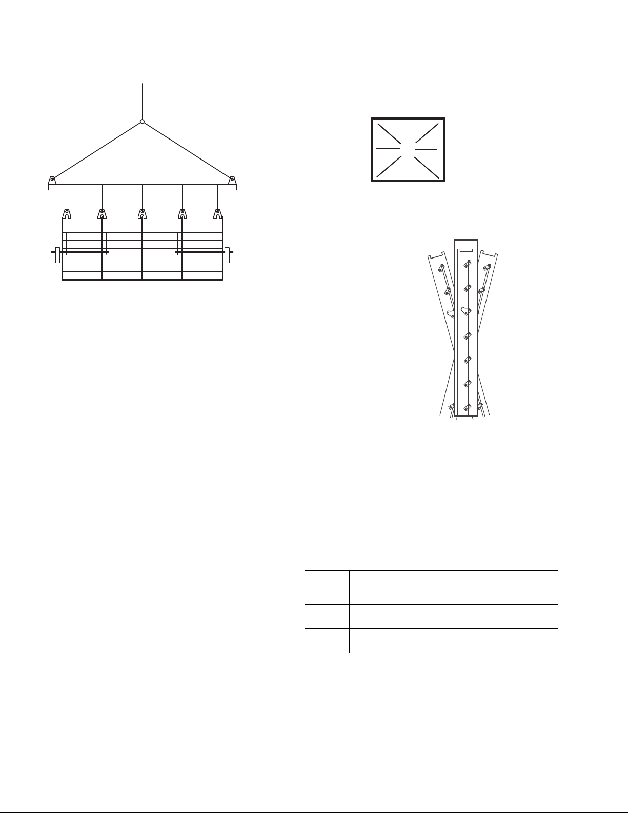
1. Duct opening or opening square should measure 1/4
inch (6mm) larger than damper dimension and should
be straight and level. See Fig. 2 and 3.
Fig. 1. Handling multiple sections assemblies.
3. Do not install screws in damper frame that will interfere
with unexposed blade linkage and prevent damper
blades from opening and/or closing.
4. Damper must be installed into duct or opening square
and free of twist or other misalignment. Damper must
not be squeezed or stretched into duct or opening. Out
of square, racked, twisted or misaligned installations
can cause excessive leakage and/or torque
requirements to exceed damper/actuator design.
5. Damper and actuator must be kept clean, dry and
protected from dirt, dust and other foreign materials
prior to and after installation. Examples of such foreign
materials include but are not limited to:
a. Mortar dust
b. Drywall dust
c. Firesafing materials
d. Wall texture
e. Paint overspray
6. Damper should be sufficiently covered as to prevent
overspray if wall texturing or spray painting will be
performed within 5 feet (1.50m) of the damper.
Excessive dirt or foreign material deposits on damper
can cause excessive leakage and/or torque
requirements to exceed damper/actuator design.
7. ACCESS: Suitable access (actuators maintenance,
etc.) must be provided for damper inspection and
servicing. Where it is not possible to achieve sufficient
size access, it will be necessary to install a removable
section of duct.
INSTALLATION
Failure to follow instructions will void all warranties
A
C
E
B
D
AF = BE
AB = CD
F
M35709
Fig. 2. Opening dimensions should be square.
DO NOT TWIST
OR BOW. MOUNT
DAMPER PLUMB
IN THE OPENING.
M35710
Fig. 3. Damper must be straight and level.
2. If more than two sections wide, unit ships as a multiple
section assembly and a single section together. The
single section is joined to the side of the multiple section
where the jackshaft extends past the frame 4 inches
(see Fig. 4 and 5).
3. A damper assembly is not restricted to a maximum
number of sections, but must not exceed the section
sizes and overall sizes in Table 1.
Table 1. Maximum Section Sizes.
Damper
Model
Section Size W x H in.
(mm)
D2, D3 48 x 74
Maximum Single
Maximum Overall Size
for Multi-Section
Dampers
Unlimited
(1219 x 1880)
D1 60 x 74
Unlimited
(1524 x 1880)
4. The damper sections must be attached together with
#10 x 3.4in.(19mm) max. sheet metal screws, 1/4 in.
(6mm) diameter nuts and bolts, tack or spot welds, or
3.16 in. (4mm) diameter steel pop rivets. Attachments
must be spaced a maximum of 6 in. (152mm) on
centers and a maximum of 2 in. (50mm) from corners.
Attachments must be made on front face and back face
(air entering and air exiting side) of damper sections.
38-00031—01 2
Page 3

5. Two section high dampers require reinforcement using a
SEE DETAIL A
M35711
14 gauge (2mm), 5 in. (127mm) wide mullion or two
individually sleeved units stacked vertically. When using
two individually sleeved units, the sleeve acts as the
mullion, therefore no mullion is required (Mullions are
not provided by Honeywell).
6. If no holes are present in frame, drill 1/4 inch (6mm)
diameter holes at 6 inch (52mm) centers and fasten
frames together with 1/4 inch (6mm) #20 (.03mm) bolts
and nuts (see Figure 1 & 2).
6 (152)
O.C.
MAX.
D1,D2, AND D3 MODELS
2 (51)
Fig. 4. Drilling and fastening frames.
DETAIL A
M35712
Fig. 5. Detail A of drilling and fastening frames.
7. Use shims between damper frame and duct opening or
opening space to prevent distortion of frame by
fasteners holding it in place. Brace at every horizontal
mullion and vertically brace at every 8 feet (2.4m) of
damper width for strength. Dampers in high velocity
(2000 fpm [610m per second]) may require more
bracing.
NOTE: Honeywell dampers are specifically designed
and engineered for structural integrity based
on model and conditions. Attachment, framing,
mating flanges, and anchoring of damper
assemblies into openings, ductwork, or walls is
the responsibility of the installer. Design calculations for these retaining and supporting
members should be determined by field engineers for that particular installation.
8. If damper actuator is to be mounted out of the
airstream, the extension pin should extend
approximately 6 inches (152mm) beyond the frame. On
jackshafted units, the jackshaft should extend through
the jackshaft bearing assembly and approximately, 6
inches (152mm) beyond the frame.
9. Individual damper sections, as well as entire multiple
section assemblies must be completely square and free
from racking, twisting, or bending. Measure diagonally
from upper corners to opposite lower corners of each
section.
10. Damper blades, axles, and linkage must operate without
binding. Before system operation, cycle dampers after
installation to assure proper operation. On multiple
section assemblies, all sections should open and close
simultaneously.
3 38-00031—01
Page 4

D1,D2, AND D3 MODELS
NOTE: When you have a vertical damper installation,
blades must be horizontal. When blades need to
be vertical, you need a vertical blade damper.
These dampers are built so they don't crush the
jamb seal.
rusting and unnecessary friction increase. Use only a molispray oil or similar graphite based oil as regular lubricating oil
will attract dirt. Bearings. Synthetic, oil impregnated, and ball
bearings (without grease fittings) do not require lubrication.
Ball bearings with grease fittings require only minimal grease.
Closure: Remove foreign materials that may be interfering
MAINTENANCE
Honeywell's dampers are designed to be trouble free and
hassle free under normal operation. Dampers are to be
installed square and straight so as to prevent binding during
operation. The following annual damper maintenance
suggestions will help to insure proper damper operation and
with blade closure or effective sealing of the blades with each
other or with the frame.
Operation: While operating the damper through its full cycle,
check to see that the blades open and close properly. If there
is a problem, check for loose linkage, especially at the
actuator. Tighten the linkage where required.
increase the life expectancy of the damper.
Foreign Matter: Over the course of time, dirt and grime may
TROUBLESHOOTING
collect on damper surfaces. The damper surfaces should be
cleaned to prevent hindrance to airflow.
The following is a cause and correction list for common
concerns with the dampers.
Moving Parts: Make sure that parts such as linkage,
bearings, blades, etc. that are intended to move freely, can do
so. Lubricating these components can prevent possible
Table 2. Troubleshooting.
Symptom Possible Cause Corrective Action
Damper does not
fully open and/or
fully close
Frame is 'racked' causing blades to bind on jamb
seals
Actuator linkage loose Close damper, disconnect power, adjust and tighten
Adjust frame such that it is square and plumb
linkage
Defective motor Replace
Screws in damper linkage Locate screws and remove
Actuator linkage hitting wall or floor Damper installed too far into wall. Move out to line
designated on damper label
Contaminants on damper Clean with a non oil-based solvent (see
“Maintenance” on page 4)
Actuator runs hot or
makes a humming
noise
Actuator type is MP-3754 or MP-3756 (stall type
actuator)
None required since this normal for stall type
actuators
Actuator prohibited from reaching end of stroke Disconnect linkage from jackshaft, open damper,
power actuator to end of spring, tighten linkage.
Verify amp draw.
By using this Honeywell literature, you agree that Honeywell will have no liability for any damages arising out of your use or modification
to, the literature. You will defend and indemnify Honeywell, its affiliates and subsidiaries, from and against any liability, cost, or damages,
including attorneys’ fees, arising out of, or resulting from, any modification to the literature by you.
Automation and Control Solutions
Honeywell International Inc.
1985 Douglas Drive North
Golden Valley, MN 55422
customer.honeywell.com
® U.S. Registered Trademark
© 2015 Honeywell International Inc.
38-00031—01 M.S. 11-15
Printed in United States
 Loading...