

Page 1

Place Bar Code Here
D05T Compact Design Pressure
Regulating Valves
INSTALLATION INSTRUCTIONS
APPLICATION
The Honeywell Braukmann D05T Pressure Regulating
Valve is a high quality pressure regulating valve that
maintains a constant outlet pressure over a wide range of
inlet supply pressures. It is ideally suited for new
residential and light commercial construction, drip
irrigation, and applications requiring highly sensitive and
accurate regulation.
The wide inlet pressure range of the D05T gives flexibility
without compromising reduced outlet pressure accuracy
or capacity. The superior balanced single seat design
maintains a constant outlet pressure over a wide range of
inlet pressures. The non-corroding unitized cartridge
insert contains all the working parts and is easily
replaceable.
The D05T is used for water or air regulation. It is not
suitable for steam.
SPECIFICATIONS
Model: D05T Pressure Regulating Valves
Construction Materials:
Body: Bronze.
Internal Parts: Stainless steel and engineered plastic.
Regulator Mechanism: Fabric-reinforced diaphragm.
Inlet Pressure: 400 psi maximum.
Reduced Pressure Range: 15 to 90 psi.
Outlet Pressure: Factory set at 60 psi.
Differential: 14 psi minimum (inlet to outlet).
Fluid Temperature (Maximum):
Air: 158°F (70°C).
Water: 180°F (82°C).
Ambient Temperature: 33°F to 140°F (1°C to 60°C)
Pipe Sizes: 3/4 in. and 1 in. available.
Connections: Can be configured as female thread-by-
thread, single- or double-union, NPT threaded or
sweat.
Strainer Screen Size: 0.032 in. (0.8 mm)
Gauge Tap: 1/4 in. NPT (available on all models).
Approvals:
ASSE (Std. 1003) Certified.
IAPMO, CSA, and City of L.A. Listed.
Dimensions: See Fig. 1.
Water Capacities (See Table 1):
The suitability of a given regulator size is dependent on
the pressure requirements of each installation. To
determine the pressure regulator valve size required
for a specific installation, determine the following:
1. Pressure differential between inlet and outlet pres-
sure in pounds per square inch (psi),
2. Capacity in gallons per minute (gpm), and
3. Allowable reduced pressure falloff in psi.
Given these variables, use Table 1 to determine the
proper size pressure regulator valve for your application.
Example:An installation has 135 psi inlet pressure, 60 psi
outlet pressure (75 psi pressure differential). If
12 gpm capacity is required with only 10 psi falloff allowable, a 1/2 in. D05T is required.
62-3028EF-01
Page 2

D05T COMPACT DESIGN PRESSURE REGULATING VALVES
Table 1. Water Capacities.
Pressure Differential Between Inlet and Outlet
25 psi 50 psi 75 psi 100 psi or more
a
Flow
Capacity
Vel ocit y
(U.S.
gpm)
(ft/sec)
4. Open the supply valve.
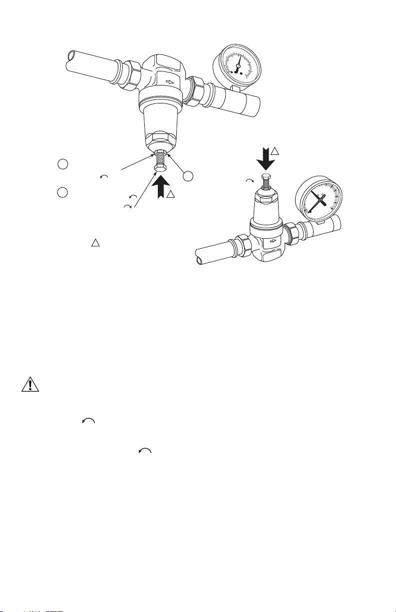
Changing the Outlet Pressure (See Fig. 1)
The D05T is factory set to 60 psi. To change the outlet
pressure, turn the adjusting bolt counterclockwise
to reduce pressure or clockwise to increase
pressure.
To adjust the outlet pressure to a desired setting:
1. Close the supply shutoff valve and open a down-
2. Loosen the locknut by turning counterclockwise
3. Turn the adjusting bolt counterclockwise sev-
4. Close all downstream valves and/or faucets and
5. Turn the adjusting bolt clockwise to gradually
6. Reopen a downstream valve. During flow, there will
7. Tighten the locknut by turning clockwise until
Pressure
Regulator
Valve
Size
3/4 inch 6 9.0 5.4 10.0 6.0 11.0 6.5 12.0 7.1
1 inch 6 11.5 4.2 13.0 4.7 14.5 5.3 16.0 5.8
a
Velocity in feet per second is based on schedule 40 pipe size. recommended pressure falloff for general use is
approximately 15 psi (104 kPa). Recommended velocities for the flow of water: Residential and general use, 5 to 10
feet per second; industrial use, 7 to 15 feet per second; boiler feed, 7 to 15 feet per second.
Reduced
Pressure
Falloff
(psi)
10 15.0 8.9 16.0 9.5 17.0 10.0 18.0 10.7
15 20.0 11.9 22.0 13.7 23.0 13.7 24.0 14.3
20 23.0 13.9 26.0 17.6 27.0 16.7 28.0 17.3
10 20.0 7.2 21.5 7.8 23.0 8.3 24.5 8.9
15 28.0 10.7 30.0 10.9 33.0 12.0 35.0 12.7
20 32.0 14.0 37.0 13.5 40.0 15.5 41.0 15.0
Flow
Capacity
(U.S.
gpm)
Velo city
(ft/sec)
INSTALLATION
When Installing this Product...
1. Read these instructions carefully. Failure to follow
them could damage the product or cause a hazardous condition.
2. Check the ratings given in these instructions and on
the product to make sure the product is suitable for
your application.
3. Installer must be a trained, experienced service
technician.
4. After installation is complete, check out the product
operation as provided in these instructions.
Procedure
1. Flush the system clear of sediment or debris.
2. Close the supply valve and downstream isolating
valve (if used).
3. Install the D05T with the arrow on the body pointing
in the direction of water flow. (The D05T can be
mounted in any position.)
The D05T can be installed directly onto the pipe by using
the female NPT threads on each end. If space limitations
restrict turning the D05T, install single- or double-unions.
NOTE: Heat from soldering can damage internal parts of
the D05T. Always remove the tailpiece(s) from
the D05T during soldering, or disassemble the
D05T prior to heating the casting.
Flow
Capacity
a
stream faucet to relieve static pressure in the line.
two turns.
eral turns to make sure the setting is below the
desired setting.
slowly open the supply valve until fully open.
increase the pressure until the gauge indicates the
desired outlet pressure (under no flow condition).
normally be a pressure falloff of 3 to 15 psi depending upon the amount of water flow.
tight. Do not overtighten.
(U.S.
gpm)
Vel ocit y
(ft/sec)
Capacity
a
Flow
(U.S.
gpm)
Velocity
(ft/sec)
a
62-3028EF—01 2
Page 3
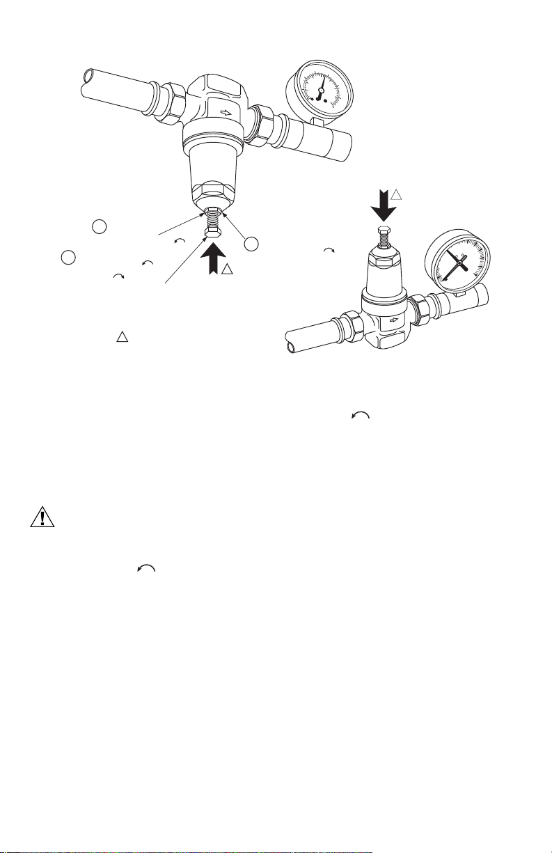
CAUTION
1
LOOSEN LOCKNUT
BY TURNING
COUNTERCLOCKWISE
TURN ADJUSTING BOLT
2
COUNTERCLOCKWISE
TO DECREASE OR
CLOCKWISE TO
INCREASE OUTLET PRESSURE
1
1
THE CLOCKWISE AND COUNTERCLOCKWISE
DIRECTIONS ARE DETERMINED BY LOOKING
DIRECTLY AT THE ADJUSTING BOLT
Fig. 1. Changing outlet pressure.
D05T COMPACT DESIGN PRESSURE REGULATING VALVES
600
800
400
100
75
125
1000
50
200
150
25
175
0
1200
0
200
PSI
HONEYWELL
kPa
1400
BRAUKMANN
1
TIGHTEN LOCKNUT BY
3
TURNING CLOCKWISE
150
200
100
water test
250
50
PSI
300
M32170
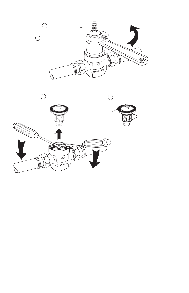
Replacing the Cartridge (See Fig.
2)
The working parts of the D05T, including diaphragm, valve
seat, strainer, and disk are all contained in a replaceable
cartridge. To replace the cartridge:
1. Shut off the supply valve and open a downstream
faucet to relieve the system pressure.
To prevent injury and/or equipment damage,
loosen locknut and turn adjusting screw
counterclockwise to remove spring tension.
2. Loosen locknut and turn adjusting screw counter-
clockwise to remove spring tension.
3. Remove the bonnet and washer using an adjust-
able wrench, socket, or box-end wrench.
4. Remove the cartridge using two screwdrivers as
levers.
5. Attach new O-rings and screen onto the new car-
tridge. Make sure O-rings are properly installed
above and below the screen.
6. Insert the new cartridge. Do not scratch the sides.
7. Place the washer on top of the cartridge.
NOTE: The inner lip must be pointing up to avoid
damaging the diaphragm.
8. Replace the spring, spring cup, and bonnet.
9. Readjust the outlet pressure to the desired setting
by using the procedure described in Changing the
Outlet Pressure section.
3 62-3028EF—01
Page 4
D05T COMPACT DESIGN PRESSURE REGULATING VALVES
2
REMOVE BONNET USING AN ADJUSTABLE
WRENCH, SOCKET, OR BOX END WRENCH
3
REMOVE CARTRIDGE USING TWO
SCREWDRIVERS AS LEVERS
4
ENSURE O-RINGS AND WASHER
ARE PROPERLY INSTALLED
O-RINGS
M761A
1
WASHER
(LIP UP)
LOOSEN LOCKNUT AND TURN ADJUSTING
SCREW COUNTER CLOCKWISE TO
REMOVE SPRING TENSION
Fig. 2. Replacing D05T cartridge.
62-3028EF—01 4
Page 5
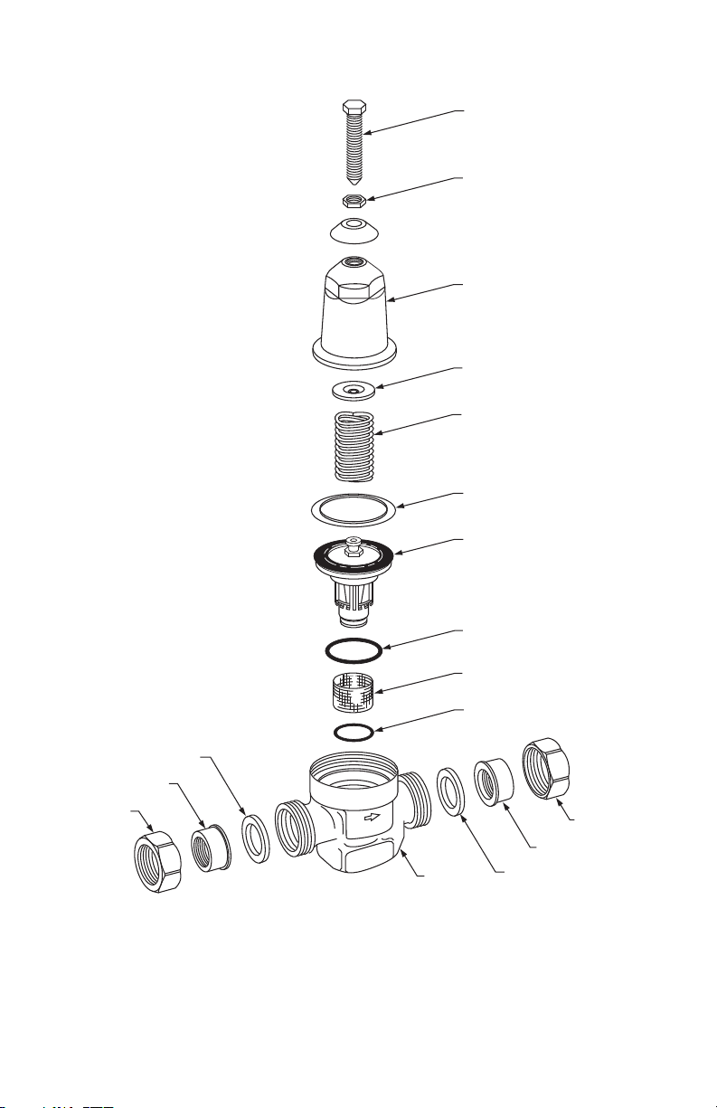
D05T COMPACT DESIGN PRESSURE REGULATING VALVES
ADJUSTING SCREW
LOCKING NUT
BONNET
SPRING CUP
SPRING
WASHER
CARTRIDGE
TAILPIECE
NUT
GASKET
Fig. 3. D05T exploded view.
5 62-3028EF—01
BODY
O-RING
SCREEN
O-RING
GASKET
NUT
TAILPIECE
M32171
Page 6

D05T COMPACT DESIGN PRESSURE REGULATING VALVES
CAUTION
Cleaning the Cartridge Screen
To clean the cartridge screen:
1. Shut off the supply valve and open a downstream
faucet to relieve the system pressure.
To prevent injury and/or equipment damage,
loosen locknut and turn adjusting screw
counterclockwise to remove spring
tension.
2. Loosen locknut and turn adjusting screw counter-
clockwise to remove spring tension.
3. Remove the bonnet and washer using an adjust-
able wrench, socket, or box-end wrench.
4. Remove the cartridge using two screwdrivers as
levers as shown in Fig. 3.
5. Remove and clean the cartridge screen.
6. Replace the cartridge screen and make sure the O-
rings are installed properly.
7. Carefully clean the cartridge seat area.
8. Insert the cartridge. Do not scratch the sides.
9. Place the washer on top of the cartridge.
NOTE: The inner lip must be pointing up to avoid
damaging the diaphragm.
10. Replace the spring, spring cup and bonnet (see Fig.
3).
11. Readjust the outlet pressure to the desired setting
by using the procedure described in Changing the
Outlet Pressure section.
OPERATION
The Honeywell Braukmann D05T is a balanced, direct
acting pressure regulating valve. The D05T provides
constant downstream pressure regardless of varying inlet
pressures and downstream flow demands.
The spring force holds the valve in the open position until
downstream pressure, sensed by a port, is sufficient to
press on the underside of the diaphragm and close the
valve. As downstream pressure drops due to demand, the
force on the diaphragm is reduced and the valve opens.
Adjustment is made by manually turning the adjustment
screw clockwise to increase the spring force and
require a higher downstream pressure to close the valve.
Similarly, reducing the spring force lowers the outlet set
pressure.
Once the outlet pressure is set, the D05T regulates to
maintain that pressure downstream. See Fig. 4 for the
internal construction of the D05T.
62-3028EF—01 6
INLET OUTLET
M32172
Fig. 4. Internal construction of the D05T.
Page 7

D05T COMPACT DESIGN PRESSURE REGULATING VALVES
TROUBLESHOOTING
Table 2 provides a troubleshooting guide for the D05T Pressure Regulating Valves.
Table 2. Troubleshooting D05T Pressure Regulating Valves.
Problem Solution
Whistling noise. • Slightly increase or decrease the outlet pressure until the noise disappears.
Will not hold pressure. • Clean the filter cartridge as shown on page 2.
Chatters. • Replace the screen and O-rings.
Freezes up. • Replace bonnet or cartridge if damaged.
Pressure gauge measures a lower
pressure under flow conditions than
was originally set during static
conditions.
D05 Parts and Accessories
Order Number Description
Replacement Parts
203223 Bonnet Assembly for 3/4 in. Valves.
203224 Bonnet Assembly for 1 in. Valves.
272841 Gasket or 3/4 in. D05T/DS05 (quantity
272842 Gasket for 1 in. D05T/DS05 (quantity
K05A1009 Replacement Cartridge, Screen and
K05A1017 Replacement Cartridge, Screen and
K05B1007 Replacement Screen and O-ring for 3/
24).
24).
O-ring for 3/4 in. Valves.
O-ring for 1 in. Valves.
4 in. Valves.
• Open the gauge tap and blow out any dirt (D05G only).
• Replace the cartridge as shown on page 2.
• To avoid future freeze-up:
—Temporarily (slightly) open a downstream faucet if the D05T is going to be
exposed to temperatures below 32°F (0°C). The slight water flow will eliminate
freeze-up.
—Move the D05T to a location with an ambient temperature above 32°F (0°C)
if it is currently exposed to prolonged temperatures below 32°F (0°C).
• D05T is functioning properly. No action is necessary. The pressure
decrease is characteristic of all direct acting pressure regulating valves and
is referred to as fall-off.
K05B1015 Replacement Screen and O-ring for 1
Union Kits
K06U1077 Union Kit — 3/4 in., includes nut,
K06U1085 Union Kit — 1 in., includes nut, female
K06U1101 Union Kit — 3/4 in., includes nut,
K06U1119 Union Kit — 1 in., includes nut, sweat
in. Valves.
female NPT threaded tailpiece and
gasket.
NPT threaded tailpiece and gasket.
sweat tailpiece and gasket.
tailpiece and gasket.
7 62-3028EF—01
Page 8

Automation and Control Solutions
Honeywell International Inc.
1985 Douglas Drive North
Golden Valley, MN 55422
Honeywell Limited-Honeywell Limitée
35 Dynamic Drive
Toronto, Ontario M1V 4Z9
customer.honeywell.com
® U.S. Registered Trademark
© 2010 Honeywell International Inc.
62-3028EF—01 T.D. Rev. 07-10
Printed in U.S.A.
Page 9

Place Bar Code Here
Régulateurs de Pression
Compacts D05T
NOTICE D'INSTALLATION
APPLICATION
Le régulateur de pression Braukmann D05T de
Honeywell est un régulateur de pression de qualité
supérieure maintenant une pression de sortie constant
sur une large plage de pressions d'entrée. Il est
parfaitement adapté aux constructions neuves
résidentielles et petits bâtiments commerciaux, aux
applications d'irrigation goutte à goutte, et aux autres
applications nécessitant une régulation très sensible et
précise.
La grande plage de pressions d'entrée du D05T offre
flexibilité sans compromettre la précision et la capacité
de la pression de sortie réduite. La conception
supérieure à siège unique équilibré maintient une
pression de sortie constante sur une large plage de
pressions d'entrée. La cartouche unitaire résistante à la
corrosion contient toutes les pièces actives et se
remplace facilement.
Le D05T est utilisé pour la régulation de l'eau et de l'air. Il
n'est pas compatible avec la vapeur.
CARACTÉRISTIQUES
Modèle: Régulateurs de pression D05T
Matériaux de construction:
Corps: Bronze.
Pièces internes: Acier inoxydable et plastique technique.
Mécanisme de régulation: Membrane renforcée de tissu.
Pression d'entrée : 400 psi maximum.
Plage de pression réduite: 15 à 90 psi.
Pression de sortie: étalonnée en usine à 60 psi.
Pression différentielle: 14 psi minimum (entrée à sor-
tie).
Tailles de conduit: 3/4 po et 1 po disponibles.
Connexions: Peut être configuré avec filetage femelle,
raccord simple ou double, à filetage NPT ou à souder.
Taille du filtre de tamis: 0,8 mm (0,032 po)
Prise de manomètre: 1/4 po NPT (disponible sur tous
les modèles).
Homologations:
Certifié ASSE (norme (1003).
Répertorié IAPMO, CSA et Ville de Los Angeles.
Dimensions: Voir la Fig. 1.
Contenances en eau (voir le Tableau 1) :
L'applicabilité d'une taille de régulateur donnée dépend
des exigences de pression de chaque application.
Pour déterminer la taille du régulateur requis pour une
installation spécifique, déterminer les points suivants:
12. Pression différentielle entre l'entrée et la sortie en
psi (livres/po2),
13. Capacité en gallons par minute (gal./min), et
14. Affaiblissement de pression réduite permis en psi.
En fonction de ces variables, utiliser le tableau 1 pour
déterminer la taille du régulateur de pression
correspondant à l'application.
Exemple:Une installation comporte une pression d'entrée
de 135 psi, une pression de sortie de 60 psi (différentiel de 75 psi). Si une capacité de 12 gal./
min est requise avec un affaiblissement permis
de 10 psi uniquement, un régulateur D05T de ½
po est requis.
Température de fluide (maximum):
Air : 70°C (158°F).
Eau : 82°C (180°F).
Température ambiante: 1 °C à 60 °C (33 °F à 140 °F)
62-3028EF-01
Page 10

RÉGULATEURS DE PRESSION COMPACTS D05T
Tableau 3. Contenances en eau.
Pression différentielle entre l'entrée et la sortie
25 psi 50 psi 75 psi 100 psi ou plus
Taille du
régulateur
pression
3/4 po 6 9.0 5.4 10.0 6.0 11.0 6.5 12.0 7.1
a
La vitesse en pied/s est basée sur une taille de conduit de schedule 40. L'affaiblissement de pression recommandé
pour un usage général est d'environ 15 psi (104 kPa). Vitesses recommandées pour le débit d'eau : Usage général et
résidentiel, 5 à 10 pi/s (1,5-3,0 m/s); usage industriel, 7 à 15 pi/s (2,1-4,6 m/s); alimentation de chaudière, 7 à 15 pi/s
(2,1-4,6 m/s).
Affaiblisse-
de
1 po 6 11.5 4.2 13.0 4.7 14.5 5.3 16.0 5.8
ment de
pression
réduite (psi)
Débit (gal.
US/min)
10 15.0 8.9 16.0 9.5 17.0 10.0 18.0 10.7
15 20.0 11.9 22.0 13.7 23.0 13.7 24.0 14.3
20 23.0 13.9 26.0 17.6 27.0 16.7 28.0 17.3
10 20.0 7.2 21.5 7.8 23.0 8.3 24.5 8.9
15 28.0 10.7 30.0 10.9 33.0 12.0 35.0 12.7
20 32.0 14.0 37.0 13.5 40.0 15.5 41.0 15.0
Vitesse
(pi/s)
a
Débit (gal.
US/min)
Vitesse
(pi/s)
Débit (gal.
a
US/min)
Vitesse
(pi/s)
Débit (gal.
a
US/min)
Vitesse
(pi/s)
a
INSTALLATION
Lors de l'installation du produit...
1. Lire attentivement ces instructions. Le non-respect
des instructions peut endommager le produit ou
provoquer une situation dangereuse.
2. Vérifier les caractéristiques nominales indiquées
dans cette notice et sur le produit pour s'assurer
que le produit correspond bien à l'application prévue.
3. L'installateur doit être un technicien expérimenté
ayant reçu la formation adéquate.
4. Une fois l'installation terminée, vérifier que le pro-
duit fonctionne comme indiqué dans cette notice.
Procédure
1. Purger le système de tout sédiment ou débris.
2. Fermer le robinet d'arrivée et le robinet d'isolement
en aval (le cas échéant).
3. Installer le D05T avec la flèche sur le corps pointant
dans la direction du débit d'eau. (Le D05T peut être
monté dans n'importe quelle position.)
Le D05T peut être installé directement sur le conduit en
utilisant un filetage NPT femelle à chaque extrémité. Si
des restrictions au niveau de l'espace empêchent de
tourner le D05T, installer des raccords simples ou
doubles.
REMARQUE : La chaleur dégagée par le soudage peut
endommager les pièces internes du D05T.
Toujours retirer le ou les embouts du D05T
durant le soudage, ou démonter le D05T
avant de chauffer le moulage.
4. Ouvrir le robinet d'alimentation.
Modification de la pression de sortie (voir la Figure 1)
Le D05T est réglé en usine à 60 psi. Pour modifier la
pression de sortie, tourner le boulon de réglage dans le
sens antihoraire pour réduire la pression et dans le
sens horaire pour augmenter la pression.
Pour régler la pression de sortie à un réglage désiré:
1. Fermer le robinet d'alimentation et ouvrir un robinet
en aval pour dissiper la pression statique dans le
conduit.
2. Desserrer l'écrou de blocage en le tournant de deux
tours dans le sens antihoraire .
3. Tourner le boulon de réglage de plusieurs tours
dans le sens antihoraire pour s'assurer que
le réglage est inférieur au réglage désiré.
4. Fermer tous les robinets et/ou vannes en aval et
ouvrir lentement le robinet d'alimentation jusqu'à ce
qu'il soit complètement ouvert.
5. Tourner le boulon de réglage dans le sens horaire
pour augmenter graduellement la pression
jusqu'à ce que le manomètre indique la pression de
sortie désirée (dans des conditions sans débit).
6. Ouvrir de nouveau la vanne en aval. Durant le
débit, il y aura normalement un affaiblissement de
la pression de 3 à 15 psi en fonction du débit d'eau.
7. Serrer l'écrou de blocage en le tournant dans le
sens horaire jusqu'à ce qu'il soit bien serré.
Ne pas trop serrer.
62-3028EF—01 10
Page 11
MISE EN GARDE
1
DESSERRER L’ÉCROU DE
BLOCAGE EN TOURNANT
DANS LE SENS
ANTIHORAIRE
TOURNER LE BOULON DE RÉGLAGE
2
DANS LE SENS ANTIHORAIRE
POUR RÉDUIRE LA PRESSION DE
SORTIE OU DANS LE SENS
HORAIRE POUR L’AUGMENTER
1
LES SENS HORAIRE ET ANTIHORAIRE SONT
DÉTERMINÉS EN REGARDANT DIRECTEMENT
LE BOULON DE RÉGLAGE
RÉGULATEURS DE PRESSION COMPACTS D05T
600
800
400
100
75
125
1000
50
200
150
25
175
0
1200
0
200
PSI
HONEYWELL
kPa
1400
BRAUKMANN
SERRER L’ÉCROU DE
3
BLOCAGE EN TOURNANT
DANS LE SENS HORAIRE
1
Fig. 5. Modification de la pression de sortie.
1
150
200
100
water test
250
50
PSI
300
MF32170
Remplacement de la cartouche (voir la Figure 2)
Les pièces actives du D05T, y compris la membrane, le
siège de vanne, le tamis et le disque, sont toutes
contenues dans une cartouche remplaçable. Pour
remplacer la cartouche:
1. Fermer le robinet d'arrivée et ouvrir un robinet en
aval pour dissiper la pression du système.
Pour éviter les blessures et/ou les dégâts
matériels, desserrer l'écrou de blocage et
tourner la vis de réglage dans le sens
antihoraire pour dissiper la tension du
ressort.
2. Desserrer l'écrou de blocage et tourner la vis de
réglage dans le sens antihoraire pour dissiper la tension du ressort.
3. Retirer le chapeau et la rondelle avec une clé
réglable, une douille ou une clé polygonale.
4. Retirer la cartouche en se servant de deux tourne-
vis comme leviers.
5. Attacher des joints toriques et un tamis neuf sur la
cartouche neuve. S'assurer que les joints toriques
sont bien installés au-dessus et en dessous du
tamis.
6. Insérer la cartouche neuve. Ne pas rayer les côtés.
7. Placer la rondelle sur la cartouche.
REMARQUE : La lèvre interne doit pointer vers le
8. Replacer le ressort, la coupelle du ressort et le cha-
peau.
9. Régler de nouveau la pression de sortie au réglage
désiré en utilisant la procédure décrite dans la section Modification de la pression de sortie.
haut pour éviter d'endommager la
membrane.
11 62-3028EF—01
Page 12

RÉGULATEURS DE PRESSION COMPACTS D05T
DESSERRER L’ÉCROU DE BLOCAGE ET
1
TOURNER LA VIS DE RÉGLAGE DANS
LE SENS ANTIHORAIRE POUR DISSIPER
LA TENSION DU RESSORT
RETIRER LE CHAPEAU AVEC UNE CLÉ
2
RÉGLABLE, UNE DOUILLE OU UNE CLÉ
POLYGONALE
RETIRER LA CARTOUCHE EN UTILISANT
3
DEUX TOURNEVIS COMME LEVIERS
RONDELLE
(LÈVRE VERS
LE HAUT)
S’ASSURER QUE LES JOINTS TORIQUES
4
ET LA RONDELLE SONT BIEN INSTALLÉS
JOINTS TORIQUES
Fig. 6. Remplacement de la cartouche D05T.
62-3028EF—01 12
MF761A
Page 13

RÉGULATEURS DE PRESSION COMPACTS D05T
VIS DE RÉGLAGE
ÉCROU DE BLOCAGE
CHAPEAU
COUPELLE DU RESSORT
RESSORT
RONDELLE
CARTOUCHE
ÉCROU
EMBOUT
JOINT
Fig. 7. Vue éclatée du D05T.
13 62-3028EF—01
CORPS
JOINT TORIQUE
TAMIS
JOINT TORIQUE
ÉCROU
EMBOUT
JOINT
MF32171
Page 14

RÉGULATEURS DE PRESSION COMPACTS D05T
CAUTION
Nettoyage du tamis de la cartouche
Pour nettoyer le tamis de la cartouche:
1. Fermer le robinet d'arrivée et ouvrir un robinet en
aval pour dissiper la pression du système.
Pour éviter les blessures et/ou les dégâts
matériels, desserrer l'écrou de blocage et
tourner la vis de réglage dans le sens
antihoraire pour dissiper la tension du
ressort.
2. Desserrer l'écrou de blocage et tourner la vis de
réglage dans le sens antihoraire pour dissiper la tension du ressort.
3. Retirer le chapeau et la rondelle avec une clé
réglable, une douille ou une clé polygonale.
4. Retirer la cartouche en se servant de deux tourne-
vis comme leviers, comme illustré dans la figure 3.
5. Retirer et nettoyer le tamis de la cartouche.
6. Replacer le tamis de la cartouche et s'assurer que
les joints toriques sont bien installés.
7. Bien nettoyer la zone du siège de la cartouche.
8. Insérer la cartouche. Ne pas rayer les côtés.
9. Placer la rondelle sur la cartouche.
REMARQUE : La lèvre interne doit pointer vers le
10. Replacer le ressort, la coupelle du ressort et le cha-
peau (voir la figure 3).
11. Régler de nouveau la pression de sortie au réglage
désiré en utilisant la procédure décrite dans la section Modification de la pression de sortie.
haut pour éviter d'endommager la
membrane.
FONCTIONNEMENT
Le D05T Braukmann de Honeywell est un régulateur de
pression à action directe équilibré. Il fournit une pression
descendante constante indépendamment des variations
des pressions d'entrée et des exigences de débit
descendant.
La force du ressort maintient le régulateur en position
ouverte jusqu'à ce que la pression descendante, captée
par un orifice, soit suffisante pour appuyer sur le côté
inférieur de la membrane et fermer le régulateur. Au fur et
à mesure que la pression descendante chute suite à la
demande, la force sur la membrane est réduite et le
régulateur s'ouvre. Le réglage se fait en tournant
manuellement la vis de réglage dans le sens horaire
pour augmenter la force du ressort et nécessiter
une pression descendante supérieure pour fermer la
vanne. De même, la réduction de la force du ressort
réduit la pression de sortie.
Une fois la pression de sortie réglée, le D05T assure une
régulation pour maintenir cette pression descendante.
Voir la figure 4 pour la construction interne du D05T.
62-3028EF—01 14
ENTRÉE SORTIE
MF32172
Fig. 8. Construction interne du D05T.
Page 15

RÉGULATEURS DE PRESSION COMPACTS D05T
DÉPANNAGE
Le tableau 2 fournit un guide de dépannage des régulateurs de pression D05T.
Tableau 4. Dépannage des régulateurs de pression D05T.
Problème Solution
Bruit sifflant. • Augmenter ou réduire légèrement la pression de sortie jusqu'à ce que le
La pression ne se maintient pas. • Nettoyer la cartouche du filtre comme illustré à la page 2.
Murmure. • Remplacer le tamis et les joints toriques.
Congélation. • Remplacer le chapeau ou la cartouche s'ils sont endommagés.
Le manomètre mesure une pression
mesurée dans des conditions de débit
inférieure à celle réglée lors de
conditions statiques.
Pièces et accessoires du D05
Description Commande
du numéro
Pièces de rechange
203223 Chapeau pour vannes de 3/4 po.
203224 Chapeau pour vannes de 1 po.
272841 Joint pour D05T/DS05 de 3/4 po
272842 Joint pour D05T/DS05 de 1 po
K05A1009 Cartouche, tamis et joint torique de
K05A1017 Cartouche, tamis et joint torique de
K05B1007 Tamis et joint torique de rechange
(quantité 24).
(quantité 24).
rechange pour vannes de 3/4 po.
rechange pour vannes de 1 po.
pour vannes de 3/4 po.
bruit disparaisse.
• Ouvrir la prise du manomètre et dégager toute saleté en soufflant (D05G
uniquement).
• Nettoyer la cartouche comme illustré à la page 2.
• Pour éviter la congélation:
—Ouvrir provisoirement (légèrement) un robinet en aval si le D05T va être
exposé à des températures inférieures à 0°C (32°F). Le léger débit d'eau
permettra d'éliminer le gel.
—Mettre le D05T dans un endroit où la température ambiante est supérieure à
0°C (32°F) s'il est actuellement exposé à des températures prolongées
inférieures à 0°C (32°F).
• Le D05T fonctionne correctement. Aucune action n'est requise. La
réduction de la pression est typique à tous les régulateurs de pression à
action directe et est appelée affaiblissement.
K05B1015 Tamis et joint torique de rechange
Nécessaires de raccords
K06U1077 Nécessaire de raccord — 3/4 po,
K06U1085 Nécessaire de raccord — 1 po, inclut
K06U1101 Nécessaire de raccord — 3/4 po,
K06U1119 Nécessaire de raccord — 1 po, inclut
pour vannes de 1 po.
inclut écrou, embout fileté NPT
femelle et joint.
écrou, embout fileté NPT femelle et
joint.
inclut écrou, embout à souder et joint.
écrou, embout à souder et joint.
15 62-3028EF—01
Page 16

RÉGULATEURS DE PRESSION COMPACTS D05T
Solutions de régulation et d’automatisation
Honeywell International Inc.
1985 Douglas Drive North
Golden Valley, MN 55422
Honeywell Limited-Honeywell Limitée
35, Dynamic Drive
Toronto (Ontario) M1V 4Z9
customer.honeywell.com
® Marque de commerce déposée aux É.U.
© 2010 Honeywell International Inc.
Tous droits réservés
62-3028EF—01 T.D. Rev. 07-10
Imprimé aux États-Unis
 Loading...