

Page 1

GAS DETECTION
TUBES AND SAMPLING
HANDBOOK
Second Edition
Page 2

Table Of Contents
1. INTRODUCTION .................................................................................... 3
2. QUALITY ASSURANCE PROCEDURES .................................. 5
3. OPERATION OF DETECTION TUBES AND PUMPS ........................... 7
3.1 Hand Pump Description .................................................................. 8
3.2 Tube Measurements…………………………………………... ...........8
3.2.1 Tube Description and Packaging ..................................... 8
3.2.2 Testing Hand Pump for Leaks ....................................... 10
3.2.3 Measurement Procedure ............................................... 10
3.2.4 Reading Tubes…………………………………….. .......... 13
3.3 Maintenance of the LP-1200 Piston Hand Pump .......................... 14
3.4 Selection of Sampling Pump ......................................................... 15
3.5 Operation and Maintenance of Remote Sampler .......................... 15
4. TECHNICAL INFORMATION ...............................................................19
4.1 Theory of Operation ...................................................................... 19
4.2 Explanation of Data Sheets .......................................................... 20
4.3 Humidity, Temperature, Pressure and Matrix Effects .................... 22
5. DATA SHEETS FOR GAS DETECTION TUBES ................................ 26
6. SPECIALTY TUBES ........................................................................... 103
6.1 Smoke Generating Tubes ...........................................................103
6.2 RAE-Sep™ Tubes .......................................................................105
6.3 PID Conditioning Tubes ..............................................................109
7. APPENDICES..................................................................................... 117
7.1 Appendix 1. Alphabetical Tube List ............................................ 117
7.2 Appendix 2. Tube List by Part Number ...................................... 119
7.3 Appendix 3. Detectable Compounds ..........................................121
7.4 Appendix 4. Equivalent Tubes of Other Manufacturers ..............126
7.5 Appendix 5. Conversion Factors for Gas Concentrations .......... 129
7.6 Appendix 6. Humidity Conversion Tables ................................... 130
7.7 Appendix 7. Other RAE Systems Gas Detection Products ........ 131
7.8 Appendix 8. Warranty ................................................................. 132
7.9 Appendix 9. RAE Systems Contacts .......................................... 133
Table Of COnTenTs
www.raesystems.com
1
Page 3

1. INTRODUCTION
WARNING
The products described herein will perform as designed only if they are
used, maintained, and serviced in accordance with the manufacturer’s
instructions. Failure to use, maintain, and operate products properly can
result in dangerously inaccurate readings.
INTRODUCTION
CAUTION: For safety reasons, the equipment described here-
in must be operated and serviced by qualied personnel only.
Read and understand this instruction manual completely before
operating or servicing.
ATTENTION: Pour des raisons de sécurité, ces équipments
Doivent être utilisés, entretenus et réparés uniquement par un
personnel qualié. Étudier le manuel d’instructions en entier
avant d’utiliser, d’entretenir ou de réparer l’équipement.
Custom Tubes
Please contact RAE Systems about the availability of custom tubes not
included in this handbook. Contact information is included on page 128.
Application & Technical Notes
RAE Systems’ web site includes the Application Notes and Technical
Notes cited in this handbook, as well as many others. Visit our web site at:
www.raesystems.com.
© 2013 by RAE Systems Inc. This handbook is fully protected by
copyright, and no part of it may be reproduced in any form without the
express written consent of RAE Systems Inc., 3775 N. First St., San
Jose, CA 95134-1708 USA.
INTRODUCTION
This handbook describes the use and performance of gas detection tubes and
sampling pumps manufactured by RAE Systems Inc. RAE Systems began
manufacturing gas detection tubes in 1997 and is adding many new tubes to
its product line each year. Modern production facilities and techniques allow
us to offer high-quality tubes at a highly competitive price.
Gas detection tubes were rst developed at Harvard University in the early
1900s for measuring carbon monoxide. In this method a gas sample is
pulled through a glass tube containing a reagent, and a reaction between
the gas and solid reagent forms a color that is related to the concentration
of the gas. The concept is similar to other colorimetric methods such as pH
paper for measuring acids and bases, and bleaching of dyes to determine
ozone or chlorine levels in water or air. Early tubes were designed mainly
for conned space entry, such as in the mining industry, where CO and
H2S are the main toxic gases. Since then, a large number of tubes
have been developed for a broad range of chemicals. With the coming
of OSHA regulations in the workplace in the 1970s, these compounds
have expanded from mostly inorganic, acutely toxic compounds to include
a large number of organic compounds whose health effects tend to be
more long term. Along with this change has come an increased need for
specicity in the measurements.
A few important factors limited the accuracy of early tube/hand pump systems.
First the tubes had no precalibrated markings. Some tubes were read using
a color comparison chart, which depended on the user’s interpretation of the
color. Other tubes came with an external scale that was slid into position by the
user. This introduced potential error in the position of the scale but, more important, did not allow for variations in the length of stain produced by different
batches of the same tubes. Modern tubes avoid such errors by having calibrations performed on each batch, which are then marked directly on the tubes.
A second error source was in the volume of air sampled. Early pumps were
variations of a rubber squeeze bulb that gave poor reproducibility in the
amount of compression. Later, xtures were added to the bulbs to ensure
a uniform compression and thus a xed volume. The Draeger and MSA
bellows pumps function in the same way as the squeeze bulbs, but draw in
accurate sample volumes.
2
www.raesystems.com
3
Page 4

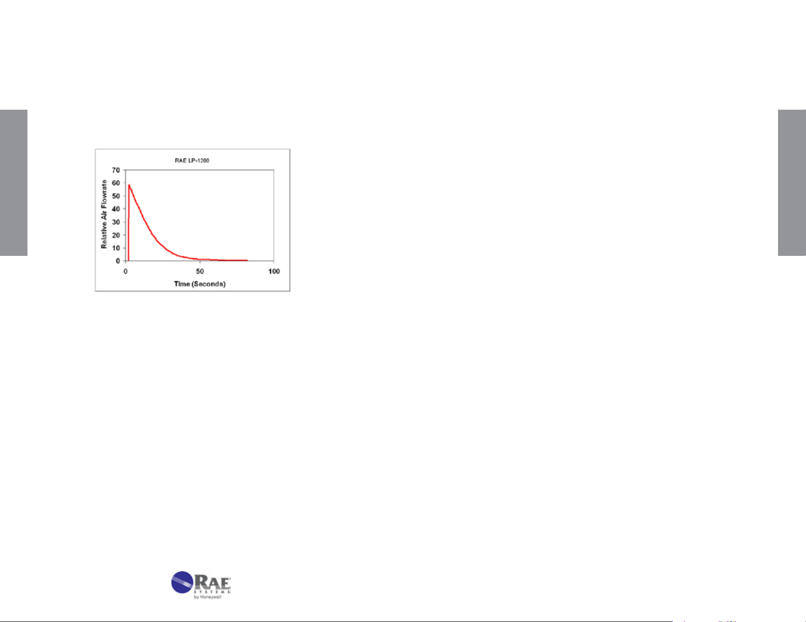
Air sampling can also be performed using piston pumps, which latch into
a precisely dened position to x the volume. These pumps pull a strong
vacuum initially and thus create substantially higher owrate than the
bellows pumps. Piston pumps generate a high ow initially followed by
an approximately exponential decay, whereas bellows pumps provide a
more steady ow initially followed by the slow decay. The difference in ow
patterns means that the pumps cannot be interchanged between types.
For example, piston pumps sometime cause a smearing of the color stain
INTRODUCTION
when used on tubes originally developed for bellows pumps. This occurs
because the higher ow rates do not allow enough contact time to give
sharp endpoints when a piston pump is used.
For a period of time, attempts were made to improve accuracy by stabilizing
the ow rate using rate-limiting orices. Some manufacturers supplied
as many as four different orice sizes to match the particular tube being
used. However, exchanging limiting orices proved to be cumbersome
and unnecessary as long as enough contact time was allowed to avoid
smearing the stain. Therefore, limiting orices have fallen out of use and
it has now become standard practice to build the ow restriction into the
tube itself. This is done by selecting the particle size of the support material
and type of end plug that give a sampling time appropriate for the particular
chemical reaction of the tube.
2. QUALITY ASSURANCE PROCEDURES FOR
GAS DETECTION TUBE MANUFACTURE
All RAE Systems gas detection tubes are developed in an ISO 9001
certied facility and manufactured in an ISO 9001 certied factory. All
procedures, work instructions, and quality records are documented and
maintained to ensure tube quality. The procedures are outlined below.
A. Tube Selection. Glass tubing is selected to t a standard bore size to
ensure uniform length of color change.
B. Support Preparation. Silica, alumina, and other support materials
are chosen from the highest quality available and sieved to yield a
narrow particle size distribution. The supports are then further puried
as necessary and dried to well-dened levels depending on the
requirements of the tube reactions.
C. Reagent Loading. Chemicals are chosen according to strict purity
standards and loaded onto the support materials. Deposition of the
chemicals onto the support follows a protocol developed specically
for each tube type. The loaded support material is then dried as
needed for the reaction.
QUALITY ASSURANCE
As a result of these developments, modern tube/pump systems have
stabilized into two categories: (1) low-vacuum bellows pumps with less
ow resistance in the tubes, by virtue of being wider (~7 mm o.d.) and
having larger particles, and (2) high-vacuum piston pumps with greater
resistance in the tubes by being narrower (~5 mm) and having smaller
particles. The bellows pump/tube systems tend to have faster sampling
but require more pump strokes to complete a measurement, whereas the
piston pump systems generally need fewer strokes but longer sampling
time per stroke. RAE Systems tubes are primarily of the narrow-bore type
and are designed for use with a piston sampling pump.
4
D. Tube Filling and Sealing. End plugs are selected of materials that
do not react with the reagent. The tubes are lled under conditions
that minimize exposure to air, water vapor, or other gases that may
affect the quality of the tubes. The tubes are then packed tightly by
a combination of shaking and physical compression. The ends of the
tubes are then melted closed using an automated ame sealer. Any
necessary inert atmosphere is maintained through the tube-sealing
process.
E. Calibration. Each batch of tubes is calibrated independently of other
batches. A series of standard gases are purchased or prepared by a
variety of methods, including ow dilution of gas primary standards,
permeation tubes, and diffusion tubes, or static dilution from liquid or
gas primary standards. Multiple tubes are used to determine each
calibration position, and these are then printed onto each tube in the
batch with an automated printing machine.
www.raesystems.com
5
Page 5
F. Packaging. The tubes and their technical data sheets are packed
into labeled boxes with protective corrugated cardboard.
G. Quality Control Sampling Plan. A portion of each batch is sent to
the RAE Systems Quality Assurance Laboratory for independent QA
testing. The most widely used tubes pass the accuracy criterion of
≤±15% of length of stain. A separate set of tubes is stored in the QA
laboratory and the manufacturing facility for evaluation at later dates,
if necessary.
3. OPERATION OF DETECTION TUBES & PUMPS
CAUTION:
Wear safety glasses and gloves when opening
tubes or handling open tubes with sharp edges.
Failure to wear protective equipment may lead to
cuts and other severe injuries to eyes and hands.
H. Accuracy and Precision. The accuracy is measured by testing
at least ve tubes and calculating the average deviation from the
standard gas value. The precision is calculated as the standard
deviation from the average value of the ve measurements. All tubes
meet the accuracy and precision criteria listed in Table 2-1:
Table 2-1. RAE Systems Tube Accuracy and Precision Specications
Tube Type
CO, CO
PH3, SO
CO, H
SO
CO, Acetone, Benzene,
MEK, Toluene, Xylene
Cl
NO
Butane, Diesel, Ethanol,
Formaldehyde, Gasoline,
OPER ATION
Methyl Bromide, Ozone,
Phenol, Trichloroethylene,
Vinyl Chloride, others
, H2O, H2S, NH3,
2
2
O , H2S, NH3, PH3,
2
2
, ClO2, HCN, HCl, HF,
2
x, NO
, RSH, RNH
2
Conc.
Range
>50 ppm 10% 10% 12%
≤50 ppm 12% 15% 20%
All 12% 15% 20%
,
2
All 20% 20% 25%
Precision
Accuracy
>20-100%
Full Scale
≤20% Full
Scale
Always test the pump for leaks immediately before
using it for a series of measurements. Failure to
test the pump for leakage may lead to dangerously
inaccurate readings.
Avoid contact with tube contents in case of
accidental breakage. Exposure to tube contents
can result in signicant health hazards.
Dispose of spent tubes according to local
regulations. Review the reaction principle and
other information listed in the Gas Detection Tube
Data Sheet supplied to identify materials that may
require special disposal procedures. (Data Sheets
for all currently available RAE Systems tubes are
included in Chapter 5.)
OPER ATION
I. Interim Storage. Only batches that pass all quality assurance
procedures are sent to interim storage, where they are maintained at
3-7°C (37 - 45°F) in darkness until shipment.
6
www.raesystems.com
7
Page 6
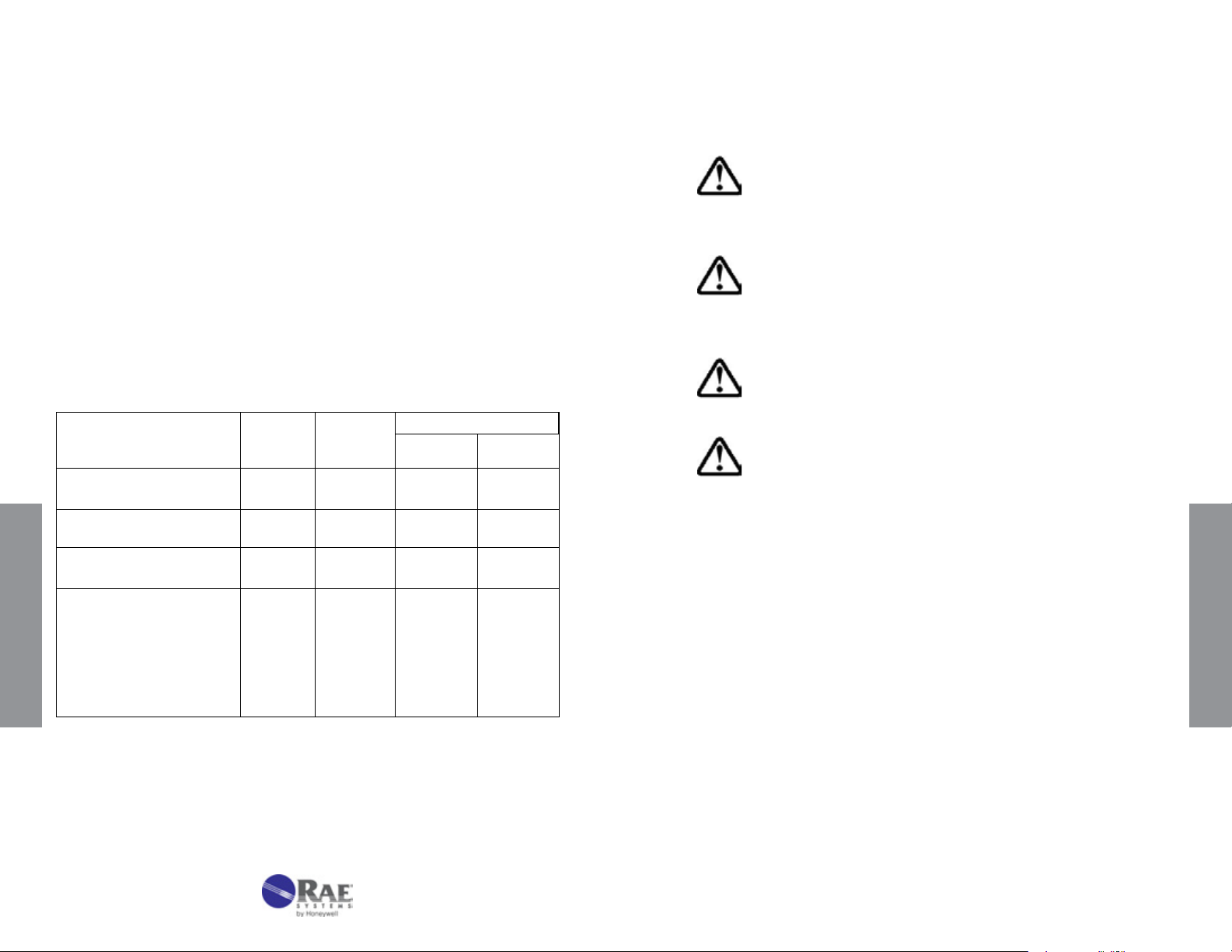
3.1 Hand Pump Description
strokes is indicated on one side, along with the total sample volume, the
unit of measure, the gas type, and the batch number.
2. Data Sheet. Each box is packaged with a Data Sheet that provides
detailed information on the tube performance. Figure 3-3 is an excerpt
of a typical data sheet. Complete data sheets are provided in Chapter
5 and discussed in detail in Chapters 4.2 and 4.3.
Figure 3-1. LP-1200 Hand Pump with tube inserted.
The LP-1200 is a piston-type hand pump that draws a xed volume of
gas, selectable at either 50 mL or 100 mL by rotating the handle. A tight
vacuum seal is formed by a greased plunger gasket. The tapered rubber
inlet accommodates a range of tube diameters for different types of tubes.
The inlet lter prevents glass pieces and dust from entering the shaft. An
end-of-ow indicator in the handle turns white when the gas sampling is
complete. A pump stroke counter is rotated to keep track of the number
of strokes completed.
3.2 Tube Measurements
3.2.1 Tube Description & Packaging
OPER ATION
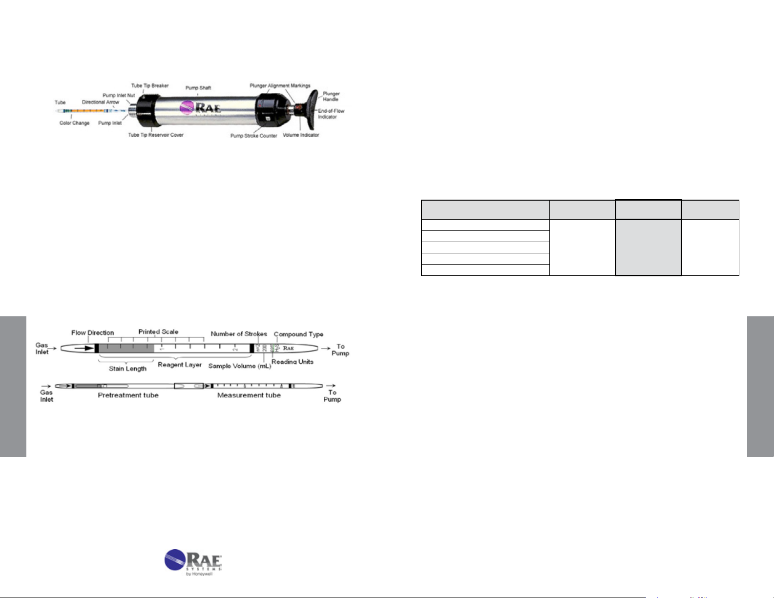
1. Tube and Box. Figure 3-2 shows the key components of a RAE
Figure 3-2. Gas detection tube parts description.
Top: Standard single tube. Bottom: Pretreatment tube
connected to measurement tube with rubber connector.
Systems gas detection tube. The tubes are typically packaged in a box
of 10 tubes. Each box has quick instructions on the back. Some tubes
require preconditioning of the gas and are packaged with 5 pretreatment
tubes and 5 measurement tubes for a total of 5 measurements. The
concentration scale is printed on the tube and an arrow indicates the
direction in which the gas must enter. The standard number of 100 mL
Gas Detection Tube Data Sheet
Hydrogen Sulde H
Extended
Range
Range (ppmv) 12.5 - 125
No. of Pump Strokes
Sample Volume (mL)
Sample Time (min)
Correction Factor (CF)
Figure 3-3. Excerpt of a Tube Data Sheet
3. Part Number. The 7-digit part number is indicated on the top right of
the data sheet. The second 3 digits indicate the tube chemical type,
and the last two digits number indicate the approximate range of the
tube. The higher the number, the higher the range.
4. Sampling Volume and Time. Using the standard number of pump
strokes, the concentration of the gas is read from stain length directly
matched to the printed scale after the listed sampling time has elapsed.
However, the range of the tube may be extended by using a smaller
or larger sample volume. In such cases, the scale reading must be
multiplied by a Correction Factor (CF) to adjust for the different sample
size. For example, the RAE Systems 10-103-18 hydrogen sulde tube
has a standard range of 25-250 ppm. When used with the standard
one stroke, the readings will correspond directly to the printed scale
on the tube. When used with half a stroke, a Ccorrection Factor (CF)
of 2 is applied. An observed reading of 50 ppm then corresponds to
an actual concentration of:
50 x 2 = 100 ppm
S No. 10-103-18
2
Standard
Range
25 - 250
2 1 0.5
200 100 50
2 x 1 1 1
0.5 1 2
Extended
Range
50 - 500
OPER ATION
8
www.raesystems.com
9
Page 7
5. Cross-sensitivity. Gas detection tubes are generally quite selective,
but some compounds may interfere in the measurements. The Data
Sheet lists possible interfering compounds; others may also exist. In
most cases these compounds increase the stain length, but in some
cases they decrease the stain length. The user must be aware of
potential interferences, or incorrect readings may result.
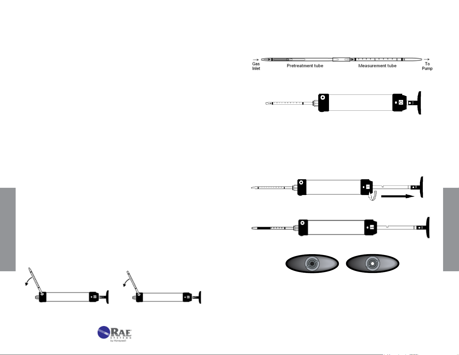
2. In cases where a pre-tube is provided (e.g., Benzene 10-101-01 and
NOx 10-109-20), connect the pre-tube to the measurement tube using
the rubber connector in the direction indicated on the tube.
3.2.2 Testing Hand Pump For Leaks
Before a series of measurements, the pump used must be tested for leaks.
Follow this procedure:
1. Insert an unopened tube snugly into the inlet of the aspirating pump.
2. Align the red dot on the plunger with the red dot on the pump shaft.
3. Pull the plunger one full stroke and wait 2 minutes.
4. Rotate the plunger dot away from the pump shaft alignment mark,
and allow the plunger to be drawn back into the pump shaft. Keep
your hand on the shaft to keep it from snapping back too suddenly.
There are no leaks if the plunger returns to within 3 mm of its original
position. If a leak is detected, refer to Section 3.3 for maintenance
procedures.
3.2.3 Measurement Procedure
1.
Break both ends of a new detection tube using the tip breaker on the
side of the pump. Insert the tube until it stops, and then back off about 1
mm before breaking off the tip. The latter procedure allows the tip to fall
OPER ATION
into the tip reservoir at the end of the pump shaft. The reservoir can be
emptied by opening the rubber cover on the opposite side of the pump.
3. Insert the measurement tube securely into the rubber pump inlet. Point
the tube arrow towards the pump (see Figs. 3-1 and 3-2).
Insert open tube with arrow pointing towards pump.
4. Select the sample volume desired and align the red dot on the plunger
with the red dot on the pump shaft. Pull the handle quickly until it
latches at ½ or 1 full stroke (50 or 100 mL) and wait for the sampling
time indicated on the data sheet to allow the air to be drawn through
the tube. The end-of-ow indicator is dark during sampling. Flow is
complete when the end-of-ow indicator returns to its white color.
Withdraw plunger sharply until it locks in place, and rotate stroke counter.
Wait for indicated sampling time when end-of-ow indicator turns white.
OPER ATION
Break tube open at both ends.
10
End-of-ow indicator is dark when sampling (left) and white when
sampling is complete (right).
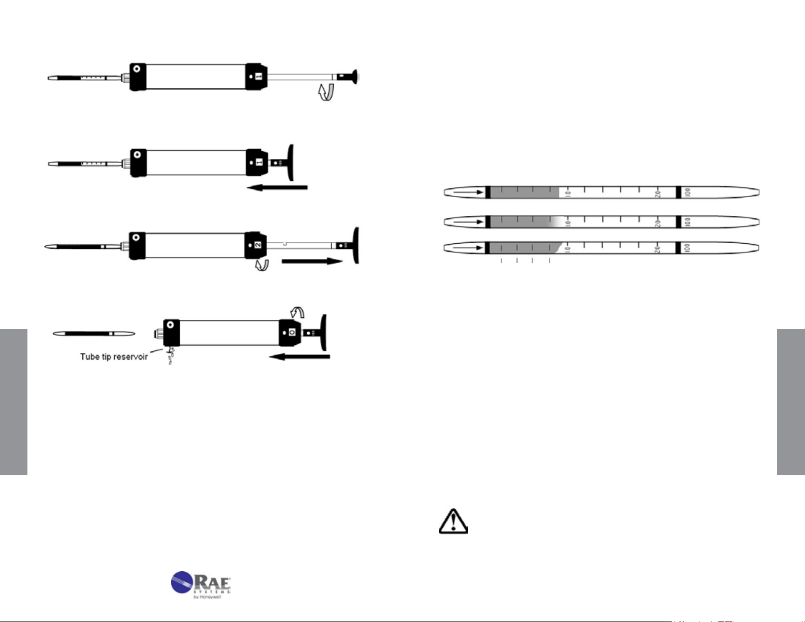
5. For additional pump strokes, rotate the handle ¼ turn clockwise or
counterclockwise and push it back fully without removing the tube from
www.raesystems.com
11
Page 8
3.2.4 Reading Tubes
1. The concentration of the compound being measured is read directly
from the scale printed on the tube.
the pump. Then repeat Step 4.
If additional strokes are needed, rotate plunger 90 degrees.
Push plunger back into pump shaft without removing tube.
Withdraw plunger for second stroke and repeat strokes as necessary.
Remove and read tube; return plunger and stroke counter to original position;
empty tube tip reservoir as necessary.
OPER ATION
2. The reading is taken as the furthest distance along the tube that the
color change just becomes visible. If the leading edge is diagonal
instead of perpendicular to the axis of the tube, use the average of the
minimum and maximum values. The three tubes shown in Figure 3-4
are all read as 0.9.
Figure 3-4. Reading of various types of endpoints after sampling.
3. Read the tube immediately after gas sampling, as colors may change,
fade, or disperse with time.
4. If a non-standard number of pump strokes was used for sampling,
multiply the reading by the Correction Factor given on the tube Data
Sheet (Chapter 5).
5. If humidity and temperature corrections are necessary as indicated on
the Data Sheets, multiply the observed readings by the given Correction
Factor(s) (CF) to obtain the true concentration. For more details and a
theoretical discussion, see Chapter 4.3 on the effects of humidity and
temperature.
OPER ATION
12
6. The user must be aware of potential interfering compounds in the tube
measurements. Interferences can be either positive or negative.
CAUTION: Always examine the data sheet and other
available information for possible interferences. Failure to
consider interferences may lead to dangerously inaccurate
readings.
www.raesystems.com
13
Page 9
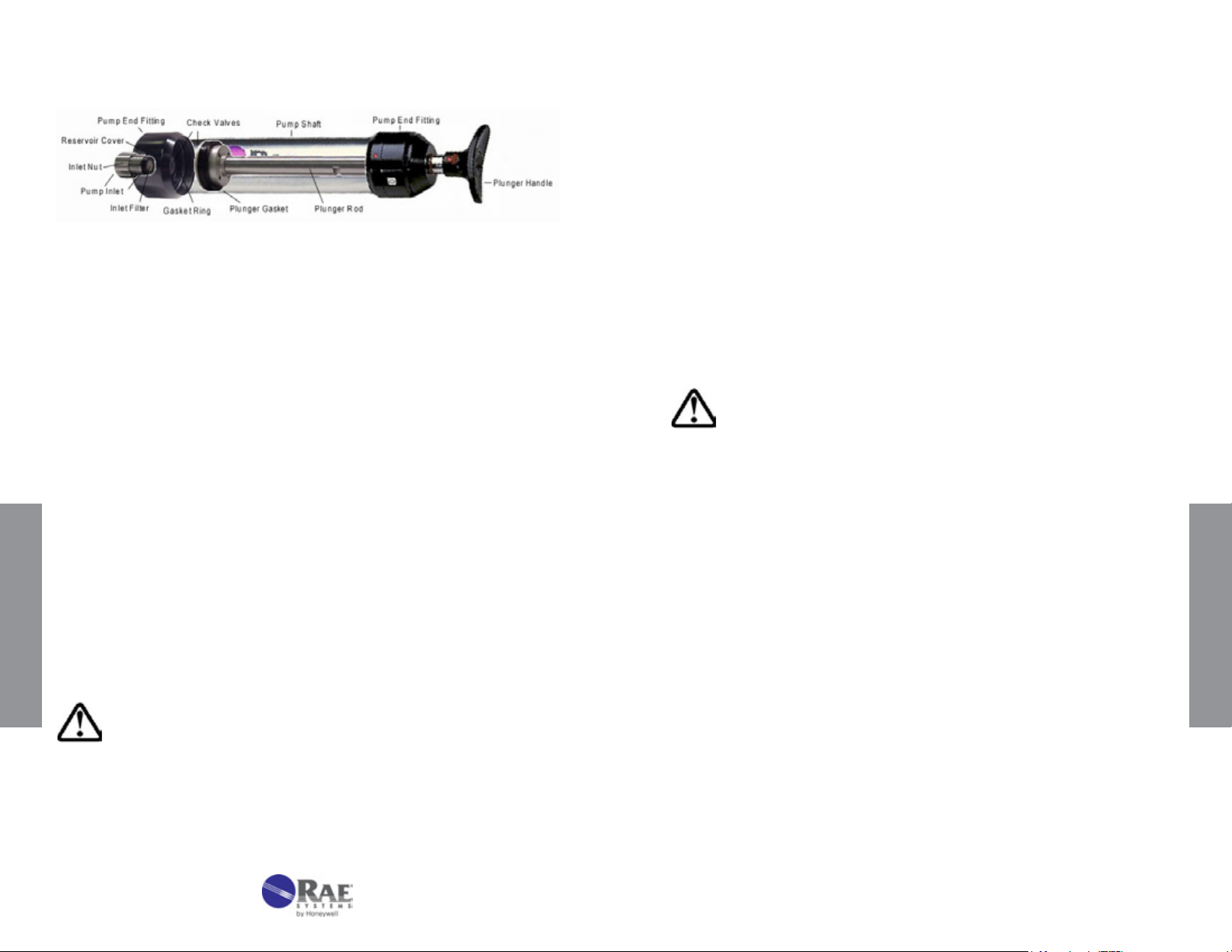
3.3 Maintenance of the LP-1200 Piston Hand Pump
Replace the outlet check valve gasket if there is resistance on the
return stroke. Using the special tool or needle-nose pliers, unscrew
the plunger tip from the plunger rod. Replace the O-ring, check valve
gasket as necessary, and reassemble. Inspect the gasket ring in the
inlet end tting. If it is damaged, replace before screwing the end tting
back on.
Figure 3-5. Transparent view of LP-1200 pump
1. Tube Tip Reservoir
Remove the tube tip reservoir cover as needed to empty the broken
glass reservoir that is in the pump end tting.
2. Pump Inlet and Filter
The rubber pump inlet can become worn with use and result in leaks.
Unscrew the pump inlet nut and replace the rubber inlet. If the inlet
is not replaced, inspect the inlet lter and replace or clean the lter
when it becomes visibly dirty or if the end-of-ow indicator on the pump
shows that the ow takes longer than recommended on the tube box.
3. Pump Mechanism
The plunger gasket may leak if it is worn or not well lubricated. To
replace the gasket:
1. Unscrew the pump end tting on the handle side.
2. Pull the plunger out of the pump shaft.
3. Replace the gasket.
4. Carefully push the plunger back into the shaft. Use a ne
OPER ATION
screwdriver or tweezers to help ease the gasket into the shaft.
5. Lubricate the inside of the shaft with vacuum grease to ensure
a good seal.
showing internal parts.
3.4 Selection Of Sampling Pump
RAE Systems tubes are designed for operation with a RAE Systems hand
pump for drawing samples through RAE Systems tubes. Pumps from
different manufacturers may have different ow patterns or deliver different
volumes, which can cause signicant errors. For example, bellows hand
pumps as supplied by MSA and Draeger have substantially different ow
patterns.
Caution: Use of a sampling pump other than a RAE Systems
hand pump may cause serious errors. Always test any pump
for leaks before use.
3.5 Operation And Maintenance Of Remote Sampler
The Detection Tube Remote Sampler is designed for use with RAE Systems
hand pumps for gas-detection tubes and adsorption tubes. The exible
Remote Sampler allows gases to be sampled through narrow apertures,
down holes, or from other areas remotely located from the sampling pump.
The sampler is available in two lengths, 15 feet (4.5 meters), p/n 010-3009015, and 35 feet (11 meters), p/n 010-3009-035.
1. Installation
OPER ATION
Caution: Do not overtighten the plunger gasket. It could cause
a sudden loss of vacuum.
The inlet check valve may cause leaks if worn or not lubricated.
Unscrew the end tting on the inlet side and pull out the disk-shaped
rubber-inlet check valve. Replace as necessary, adding a light coat of
grease around the hole.
14
Refer to Figure 3.7 for installation and part descriptions. Unscrew
the pump adapter nut and remove the standard rubber tube adapter
from the pump. Inspect the remote sampler to ensure that the porous
metal lter is in place, and screw the pump adapter nut attached to the
sampler into the pump. Store the standard nut and rubber adapter in a
safe place for later use.
2. Operation
www.raesystems.com
15
Page 10

To ensure a good seal, insert the gas detection tube into the tube
holder and twist the tube while pushing in. If the tube uses a pre-tube,
insert the pre-tube into the pre-tube holder and push the pre-tube into
the end of the standard tube holder. Secure the pre-tube holder using
the rubber buckles. Lower the extension hose to the desired position.
Figure 3-6. Installation of the remote sampling probe into
the LP-1200 hand pump.
4. Routine Maintenance
a. Porous Metal Filter: The metal frit lter should be replaced when it
becomes visibly dirty or if the end-of-ow indicator on the pump shows
that the ow takes longer than recommended on the tube box.
b. Leak Test: If a leak is discovered with either pump, rst remove the
probe and check the pump for leaks. Then examine the tubing and
connections for the leak source, as follows:
i. Hand Pump: Insert a sealed tube into the tube holder tightly. Pull
3 pump strokes to expel the air from inside the tubing. Pull a
fourth stroke and wait for 2 minutes. Rotate the plunger dot away
from the pump shaft alignment mark, and allow for the plunger
to be drawn back into the pump shaft. Keep your hand on the
shaft to prevent it from springing back too suddenly. If the plunger
returns to within 3 mm of its original position, there are no leaks.
3. Correction
Caution: In order to obtain accurate readings, the following
corrective procedures must be employed when using the 35-foot
(11-meter) remote sampler.
OPER ATION
The 35-foot (11-meter) remote sampler causes a slight delay and
reduced reading because of the extra volume in the extension
tubing. Increase the sample time by 30 seconds for a 2-minute
tube, 20 seconds for a 1.5-minute tube, and by 15 seconds
for a 1-minute tube. Then multiply the reading by 1.08 to obtain the
corrected value. Corrections for the 15-foot (4.5-meter) remote sampler
are unnecessary.
16
www.raesystems.com
OPER ATION
17
Page 11

4. TECHNICAL INFORMATION
4.1 Gas Detection Tube Theory Of Operation
Gas detection tubes operate on a chemical reaction between the vaporphase compound and a liquid or solid detecting reagent, which is supported
on an inert matrix. The most common types of reactions are the following:
• Acid-base reactions These include reactions of acidic gases like HCl
and HF with bases, and reaction of alkaline vapors such as ammonia
with an acid in the tube. A dye present in the tube changes color as
the pH changes on exposure to the vapors.
• Reduction-oxidation (Red-ox) reactions These generate an oxidized
or reduced compound, which has a different color. The chlorine tube
uses oxidative coupling of colorless o-toluidine to form an orange azodye. White di-iodine pentoxide is reduced by CO and many organic
vapors to form deep brown-colored iodine. Orange chromium (VI) is
reduced by many organic compounds to form brown or green-colored
Cr(III) compounds.
• Ligand-exchange reactions These generate new complexes that
are more colored than the starting reagents. The most notable is the
conversion of white lead acetate to brown-black lead sulde in the
detection of H
the chlorine ligand of HgCl2 releases HCl, which then causes a pHdependent dye-color change.
S. In the case of phosphine, the exchange of PH3 for
2
TECHNICAL INFORMATION
•
Pre-layers or Pre-tubes These are used to condition the sample
by controlling humidity, removing interferences, or transforming the
analyte to another detectable compound. Examples include drying
OPER ATION
18
agents in NH3 and HCl tubes, organic removal by charcoal or oxidation
in selective CO tubes, and oxidation of NO to NO2 in the nitrogen oxides
tube.
All RAE Systems detection tubes are length-of-stain types. In these
tubes, the reaction of the gas with the supported reagent is fast, compared
to the transport of the bulk air sample through the tube. Therefore, all
of the detected vapors are reacted within the tube. As a result, there is
not a strong dependence of the readings on the rate at which the gas is
sampled. However, a very high ow rate can cause some smearing to a
high reading. Conversely, low ow rates are less likely to affect the stain
www.raesystems.com
19
Page 12
length, but can give low readings by concentrating the colored products in
a shorter section of the tube. In cases of ow extremes, errors outside the
standard 25% accuracy can be produced.
RAE Systems tubes are calibrated using RAE Systems piston hand pumps.
The ow during a single pump stroke initially rises sharply and then decays
exponentially (see Figure 4-1). The best accuracy is therefore obtained
when the ow through the tube mimics this prole.
TECHNICAL INFORMATION
3. Precision. This value is determined by measuring a standard gas
sample with at least 5 randomly chosen tubes. Precision is reported
as the standard deviation from the average of the 5 measurements.
Precision is typically ≤±15%. (See Section 2 for complete table.)
4. Linearity with number of pump strokes. Multiple strokes are measured
with a gas standard with concentration at the low end of the tube.
Tubes must have correlation coefcients (r2) >0.95 to be considered
linear.
5.
Humidity. The effect on the reading as a function of humidity of the
standard gas is listed. Any required Correction Factors are tabulated.
6. Temperature. The effect of temperature is determined by equilibrating
the gas sample, tube, and pump to the test temperatures, typically 0°,
10°, 25°, and 40°C (32°, 50°, 77°, and 104°F). Any required Correction
Factors are tabulated. If humidity has a measurable effect on the gas
readings, the temperature tests are performed at constant relative
humidity (not absolute humidity). Any temperature corrections should
be multiplied by any humidity corrections to obtain true readings.
TECHNICAL INFORMATION
Figure 4-1. Piston pump internal pressure pattern. Data is offset
by 2 seconds.
4.2 Explanation Of Data Sheets
The Data Sheets supplied with each box of tubes give representative
information applying to all batches. The Data Sheets include:
1. Standard and extended measurement ranges, pump strokes
required, gas volumes required, sampling times, and the detection
limit. The standard range and strokes apply to the calibration scale
printed on the tubes. The range can usually be extended to higher
or lower concentrations by reducing or increasing, respectively, the
number of pump strokes.
2. Correction Factors (CF) for conditions of pump stroke, temperature,
humidity, or gas type other than the standard conditions. The
CF is multiplied by the observed reading to obtain the corrected
concentration.
20
7. Storage Life. Samples of tubes are stored for extended periods to
evaluate their accuracy at dened time periods to determine their
storage life. The user should store tubes in darkness at 3° to 7°C (37°
to 45°F) to maximize their shelf life. Freezing tubes (storage below
0°C, or 32°F) can damage some types and is not recommended.
8. Cross-Sensitivity. Tubes are challenged with a variety of possible
interfering gases to quantitate their relative response. Although the
tubes are highly selective, compounds that are chemically similar to
a target compound sometimes show a positive interference. Others
interfere with the measurement gas without showing a response
on their own; for example, when acidic vapors coexist with basic
vapors. Such information is listed in a separate note or column titled
“Interferes in Mixtures.” The user should know as much about the
sample environment as possible in order to make sound judgments
regarding possible interferences; otherwise inaccurate readings may
result. In some cases, a different color or pattern of the stain can clue
the user to the presence of an interfering compound.
www.raesystems.com
21
Page 13
4.3 Humidity, Temperature, Pressure, and Matrix Effects
2. Temperature
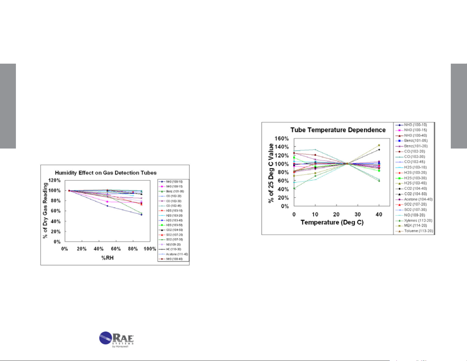
1. Humidity
Humidity has little effect on most tubes either because the reaction is
insensitive to moisture or because drying agents are added to absorb
the moisture in a pre-layer (see Figure 4-2). Humidity tends to have
the greatest effect on compounds that are highly water-soluble, such
as acids and bases. HF (hydrouoric acid) is a notable example that
requires humidity corrections; water-adsorbing prelayers cannot be
used because they tend to be reactive with HF. The humidity effect
tends to be greater as the concentration range of the tube is lowered.
When correcting for humidity, the CF is multiplied by the reading in
addition to multiplying by any temperature correction. Any necessary
TECHNICAL INFORMATION
Correction Factors are listed in the individual tube data sheets. Note
that the relative humidity at the measurement temperature denes the
correction, rather than the absolute humidity.
Temperature can affect gas tube readings in at least three ways. First,
as the temperature increases, the gas density decreases, causing a
tendency for the reading to decrease (see pressure effects described in
the next section). Second, as the temperature increases, the reaction
rate increases, causing the reading to be sharper and shorter. A third,
balancing effect is that adsorption is often a prerequisite for reaction.
Adsorption is weaker as temperature increases, and thus the reading
can become longer. The interplay of these competing effects results in
some stains that are longer with increasing temperature, and others
that are shorter.
TECHNICAL INFORMATION
Figure 4-2. Effect of humidity on gas detection tube readings.
22
Figure 4-3. Effect of temperature on gas detection tube readings.
Additional factors occur in special cases. For example, pretube or prelayer
reactions are sometimes more complete at higher temperatures,
causing higher readings in the measurement layer. In some cases,
the color of the stain can change. In the water vapor 120-20 tube, the
color stain is green at room temperature and a more purple color below
room temperature.
www.raesystems.com
23
Page 14

3. Pressure
Tubes change color in proportion to the mass of the compounds
reaching the reagent (i.e, the absolute concentration). Therefore, as
the pressure decreases at higher altitudes, the apparent response is
reduced because there are fewer molecules per unit volume sampled.
The conventional desired reading is in ppmv (parts per million by
volume), which is a relative concentration, such as a mole or volume
fraction (% of molecules of compound per molecules of total gas [air]),
rather than an absolute concentration.
All RAE Systems tubes are calibrated at 1 atmosphere (760 mm
Hg) pressure at sea level.
• For tubes calibrated in absolute concentrations such as lbs./MMCF or
TECHNICAL INFORMATION
mg/m3, no pressure corrections are needed.
Example Location Altitude
(km)
Altitude
(feet)
Pressure,
(mm Hg)
San Francisco, CA 0 0 760 1.00
Atlanta, GA 0.3 1000 731 1.04
Spokane, WA 0.6 2000 703 1.08
Rapid City, SD 0.9 3000 676 1.12
Salt Lake City, UT 1.2 4000 650 1.17
Denver, CO 1.5 5000 625 1.22
Colo. Spgs., CO 1.8 6000 601 1.27
Santa Fe, NM 2.1 7000 578 1.32
Alta, UT 2.4 8000 555 1.37
Winter Park, CO 2.7 9000 534 1.42
Keystone, CO 3.0 10000 514 1.48
4. Matrix Gas
CF
TECHNICAL INFORMATION
• For tubes calibrated in relative concentrations (e.g., ppm), correct for
pressure using one of the following equations:
Corrected reading = Observed Reading x 760 mm Hg
Pressure (mm Hg)
Corrected reading = Observed Reading x 101.3 kPa
Pressure (kPa)
Corrected reading = Observed Reading x 14.7 psia
Pressure (psia)
The pressure in mm Hg can be estimated as a function of altitude using
the following equation:
P (mm Hg) = 760exp(-0.1286[alt(km)]) below 2 km
Example Correction Factors are listed in the following table as a
function of altitude. Weather changes may also affect the atmospheric
pressure, but the necessary corrections are usually <10%.
The matrix gas usually has little or no effect on the tube readings
as long as the gas does not chemically react with the tube reagents
or measured compound. Thus, readings in air, nitrogen, hydrogen,
helium, or carbon dioxide give essentially the same results. However,
the viscosity of the gas has a signicant effect on the sampling time.
Thus, for example, the sampling time of the CO 10-102-18 tube is
about half as long in pure hydrogen (viscosity 9.0 μPa-s) as it is in air
(viscosity 18.6 μPa-s).
Viscosity
Matrix Gas
Air 18.6 1.00 90
n-Butane 7.5 0.40 36
Propane 8.3 0.45 40
Hydrogen 9.0 0.48 44
Ethane 9.5 0.51 46
Acetylene 10.4 0.56 50
Methane 11.2 0.60 54
Carbon Dioxide 15.0 0.81 73
Nitrogen 17.9 0.96 87
Helium 20.0 1.08 97
Oxygen 20.8 1.12 101
Argon 22.9 1.23 111
Neon 32.1 1.73 155
@ 27°C
(μPa-s)
Sampling Time
Relative to Air
Sampling Time
for a 90 second
Tube (seconds)
At a given viscosity, higher ow rates tend to give longer stains. However,
this is often compensated by higher diffusion rates to the reactive surface
in the less viscous gases, resulting in no signicant effect on the readings.
24
www.raesystems.com
25
Page 15

5. DATA SHEETS FOR GAS DETECTION TUBES
Acetone C3H6O No. 10-111-40
Amines RNH2 (CH3NH2) No. 10-132-10
Extended
Range
Range (ppmv)
No. of Pump Strokes
Sample Volume (mL)
Sample Time (min)
0.05 - 1% 0.1 - 2% 0.2 - 4%
2 1 0.5
200 100 50
2 x 2 2 1.5
Correction Factor 0.5
Standard
Range
1
Extended
Precision (Relative Standard Deviation)*: ≤ ±12%
2
Linearity with No. of Pump Strokes: r
= 0.992
Humidity: No effect 5 - 85% RH
Temperature Range: 0 - 40°C (32 - 104°F)
Temp (°C/°F) 0/32 10/50 25/77 40/104
Corr. Factor 1.25 1.15 1.0 0.95
Storage Life: 2 years in darkness at 5 - 25°C (40 - 77°F). Refrigeration preferred.
Color Change: Orange → Black
Reaction Principle: CH
Cross-sensitivity:
Data SheetS
Substance
Methyl ethyl ketone 0.6% 0.55% 1.1
Methyl propyl ketone
Methyl isobutyl ketone
CO
CO
2
CH
4
NH
3
S
H
2
Ethyl Acetate
Hexane
Isobutylene
Toluene
* Data based on RAE Systems pumps and tubes used in standard range.
#
Faint black color over entire stain length. Ketones can be distinguished by their
darker stains and sharp endpoints.
COCH3 + Cr(VI) + H2SO4 → Cr(III) + Oxidation Prods.
3
Concentration
(ppmv)
1.0% 0.65% 1.5
1.0% 0.40% 2.5
1.5% 0 -
1.5% 0 -
2.5% 0 -
5.0% 1.4% brown 3.6
300 0.5% diffuse
1.0% 0.85% diffuse
0.24% entire tube
0.20% entire tube
400 0.3% diffuse
Apparent
Reading*
Factor
#
#
#
#
#
Other Possible Interferences: Other hydrocarbons.
Range
2
Corr.
-
-
-
-
-
Extended
Range
Range (ppmv) 0.25 - 5 0.5 - 10 1.0 - 20
No. of Pump Strokes 2 1 0.5
Sample Volume (mL) 200 100 50
Sample Time (min) 2 x 1 1 1
Correction Factor 0.5 1.0 2.0
Standard
Range
Extended
Range
Precision (Relative Standard Deviation)*: ≤ ±20%
Linearity with No. of Pump Strokes: r
2
= 0.997
Humidity: No effect 0 - 90% RH
Temperature Range: 0 - 40°C (32 - 104°F) @ constant 50%RH.
Temp (°C/°F) 0/32 10/50 20/68 30/86 40/104
Corr. Factor 1.16 1.10 1.0 0.96 0.96
Storage Life: 1 year in darkness at 5-25°C (40-77°F). Refrigeration preferred.
Color Change: Pink → Yellow
Reaction Principle: 2RNH
Cross-sensitivity:
Substance
Ammonia 5 6.0 0.8
Methylamine 10 10* 1.0
Ethylamine 8 7.0 1.1
Allyamine 7.4 8.0 0.93
Diethylamine 5 6.3 0.79
Trimethylamine 4.5 9.8 0.46
Triethylamine 6 9.5 0.63
Methylaziridine (Propylene imine) 5 6.5 0.77
Ethylenediamine 7 2.0
Ethanolamine 36 4.1
Pyridine 10 Over range
H2S 100 0
CO 500 0
Isobutylene 100 0
HCl 1000 0
* Data based on RAE Systems pump and tubes used in standard range. This tube is
calibrated using methylamine.
#
Deep purple with yellow stain at endpoint.
†
Slight color change to light pink.
£ Interferes in mixtures.
+ H2SO4 → (RNH3)2SO4
2
Concentration
(ppmv)
Apparent
Reading*
#
#
£
†
Correction
Factor
3.5
8.8
-
Other Possible Interferences: Other bases.
Data SheetS
26
www.raesystems.com
27
Page 16

Ammonia NH3 No. 10-100-05
Extended
Range
Range (ppmv) 0.5 - 15
No. of Pump Strokes
Sample Volume (mL)
Sample Time (min)
Correction Factor
2 1 0.5
200 100 50
2 x 1.5 1.5 1
0.55 1 2.4
Standard
Range
1 - 30
Precision (Relative Standard Deviation)*: ≤ ± 12%
Linearity with No. of Pump Strokes: r
2
= 0.999
Humidity: The tubes are calibrated at 50% RH @ 24 °C (75 °F)
% RH < 5% 10% 50% 80% 95%
Corr. Factor 0.8 0.85 1.0 1.0 1.0
Temperature Range: 0 - 40°C (32 - 104°F) @ constant 50%RH
Temp (°C/°F) 0/32 10/50 25/77 35/95
Corr. Factor 0.9 0.95 1.0 1.1
Extended
Range
2 – 60
Ammonia NH3 No. 10-100-10
Extended
Range
Range (ppmv) 2.5 - 50
No. of Pump Strokes
Sample Volume (mL)
Sample Time (min)
Correction Factor
2 1 0.5
200 100 50
2 x 1 1 1
0.5 1 2
Standard
Range
5 - 100
Precision (Relative Standard Deviation)*: ≤ ± 12%
2
Linearity with No. of Pump Strokes: r
= 1.000
Humidity: @ 24 °C (75 °F) The tubes are calibrated at 50% RH.
% RH < 5% 20% 50% 70% 90%
Corr. Factor 0.7 0.8 1.0 1.1 1.3
Temperature Range: 0 - 35°C (32 - 95°F) @ constant 50% RH
Temp (°C/°F) 0/32 10/50 24/75 34/93
Corr. Factor 0.8 1.0 1.0 1.0
Extended
Range
10 – 200
Data SheetS
Storage Life: 2 years in darkness at 5 - 25°C (40-77°F). Refrigeration preferred.
Color Change: Purple → Beige
Reaction Principle: Prelayer reduces humidity effects
3NH
+ H3PO4 → (NH4)3PO4
Data SheetS
Cross-sensitivity:
Substance
3
Concentration
(ppmv)
Apparent
Reading*
Pyridine 10 15
Diethylamine
Hydrazine
Methylhydrazine
CO
CO
2
H2S
Hexane
Isobutylene
Toluene
* Data based on RAE Systems pumps and tubes used in standard range.
** These hydrazines can be measured using 2 strokes with a CF of 5.
#
16000 ppm CO2 reduces the NH3 response by 30% in mixtures, 5000 ppm CO2 reduces
NH
response by 10% in mixtures, and 1000 ppm CO2 has no effect.
3
20 18
20 2**
20 2.3**
100 0
20000 0#
200 0
100 0
100 0
100 0
Other Possible Interferences: Amines and other bases.
28
Storage Life: 2 years in darkness at 3 - 10°C (37 - 50°F). Refrigeration required.
Color Change: Purple → Beige
Reaction Principle: Prelayer reduces humidity effects
+ H3PO4 → (NH4)3PO4
3NH
3
Cross-sensitivity
:
Substance
Butylamine 100
Diethylamine
CO
S
H
2
SO
2
CH
4
CO
2
NO
2
Hexane
Isobutylene
Toluene
* Data based on RAE Systems pumps and tubes used in
Concentration
(ppmv)
#
#
50
250 0
#
100
#
100
50000 0
50000 0
200 0
100 0
100 0
100 0
Apparent
Reading*
45
60
0
0
standard range. # At 50% RH.
Other Possible Interferences: Amines and other bases.
www.raesystems.com
29
Page 17

Ammonia NH3 No. 10-100-12
Ammonia NH3 No. 10-100-15
Extended
Range
Range (ppmv) 5 - 130
No. of Pump Strokes
Sample Volume (mL)
Sample Time (min)
Correction Factor
2 1 0.5
200 100 50
2 x 1.5 1.5 1
0.5 1 2
Standard
Range
10-260
Precision (Relative Standard Deviation)*: ≤ ± 12%
Linearity with No. of Pump Strokes: r
2
= 1.000
Humidity: @ 22 °C (72 °F) The tubes are calibrated at 50% RH.
% RH < 5% 10% 50% 70% 90%
Corr. Factor 0.8 0.9 1.0 1.0 1.0
Temperature Range: 0 - 40°C (32 - 104°F) @ constant 50%RH
Temp (°C/°F) 0/32 10/50 22/72 40/104
Corr. Factor 0.8 1.0 1.0 1.0
Storage Life: 2 years in darkness at 3 - 10°C (37 - 50°F). Refrigeration required.
Color Change: Purple → Beige
Reaction Principle: Prelayer reduces humidity effects
Data SheetS
+ H3PO4 → (NH4)3PO4
3NH
3
Cross-sensitivity:
Substance
Butylamine 200
Diethylamine
CO
H
S
2
SO
2
CH
4
CO
2
NO
2
Hexane
Isobutylene
Toluene
* Data based on RAE Systems pumps and tubes used in
# At 50% RH.
Concentration
(ppmv)
#
#
200
250 0
#
100
#
100
50000 0
50000 0
200 0
100 0
100 0
100 0
Apparent
Reading*
200
260
0
0
standard range.
Other Possible Interferences: Amines and other bases.
Extended
Range
20 - 520
Extended
Range
Standard
Range
Extended
Range
Range (ppmv) 12 - 250 25 - 500 50 - 1000
No. of Pump Strokes 2 1 0.5
Sample Volume (mL) 200 100 50
Sample Time (min) 2 x 1 1 1
Correction Factor 0.56 1 2
Precision (Relative Standard Deviation)*: ≤ ± 12%
2
Linearity with No. of Pump Strokes: r
= 0.998
Humidity: No effect at 10 - 90% RH. At <5% RH multiply the reading by 0.8.
Temperature Range: 0 - 40°C (32 - 104°F) @ constant 50%RH.
Temp (°C/°F) 0/32 10/50 24/75 40/104
Corr. Factor 1.3 1.0 1.0 1.2
Storage Life: 2 years in darkness at 3 - 10°C (37 - 50°F). Refrigeration required.
Color Change: Purple → Beige
Reaction Principle: Prelayer reduces humidity effects
3NH3 + H3PO4 → (NH4)3PO
Cross-sensitivity:
Substance
Butylamine 300
Diethylamine
CO
CO
2
S
H
2
SO
2
NO2
CH
4
Hexane
Toluene
Isobutylene
* Data based on RAE Systems pumps and tubes used in standard range.
#
At 50% RH. ‡Reduces reading in mixtures
Concentration
(ppmv)
100
250 0
50000 0
250 0
500
200 0
25000 0
1500 0
200 0
5000 0
4
Apparent
Reading*
#
#
#
200
90
0
‡
Other Possible Interferences: Amines and other bases.
Data SheetS
30
www.raesystems.com
31
Page 18

Ammonia NH3 No. 10-100-40
Benzene Specic C
No. 10-101-01
6H6
Extended
Range
Range (ppmv) 0.5 - 7.5%
No. of Pump Strokes
Sample Volume (mL)
Sample Time (min)
Correction Factor
2 1 0.5
200 100 50
2 x 2 2 1.5
0.5 1 2
Standard
Range
1 - 15%
Extended
Precision (Relative Standard Deviation)*: ≤ ± 10%
Linearity with No. of Pump Strokes: r
2
= 0.999
Humidity: 85% RH reduces the reading by about 25% compared to dry air
Temperature Range: No effect 0 - 40°C (32 - 104°F)
Storage Life: 2 years in darkness at 5 - 25°C (40 - 77°F). Refrigeration preferred.
Color Change: Orange → Deep Purple
Reaction Principle: 3NH
Cross-sensitivity:
Substance
CO 3000 0
Data SheetS
CO
2
SO
2
NO
Hexane
Isobutylene
CH
4
* Data based on RAE Systems pumps and tubes used in standard range.
+ H3PO4 → (NH4)3PO
3
Concentration
(ppmv)
100000 0
200 0
100 0
100 0
1000 0
25000 0
4
Apparent
Reading*
Other Possible Interferences: Amines and other bases
Range
2 - 30%
Extended
Range
Range (ppmv) 0.25 - 5
No. of Pump Strokes
Sample Volume (mL)
Sample Time (min)
Correction Factor
6 3 1
600 300 100
6 x 3 3 x 3 3
0.27 1 4
Standard
Range
0.5-10
Extended
Range
1.5 - 30
Precision (Relative Standard Deviation)*: ≤±12%
Humidity: No effect 0 - 95% RH
Temperature Range: 0 - 40°C (32 - 104°F)
Temp (°C/°F) 0/32 10/50 25/77 40/104
Corr. Factor 2.7 1.6 1.0 0.6
Storage Life: 1 year in darkness at 5 - 25°C (40 - 77°F). Refrigeration preferred.
Color Change: White → Brown
Reaction Principle: Pretube removes interferences
+ CH2O → diphenylmethane + H2O
2C
6H6
→ p-quinoid products
2S2O7
Apparent
Reading*
Cross-sensitivity:
Substance
diphenylmethane + H
Concentration
(ppmv)
Isobutylene 100 0
n-Hexane 500
#
0
n-Heptane 100 0
Toluene 100 0
m-Xylene 50 0
m-Xylene 100 5
CH
4
25000 0
CO 10 0
H2S 25 0
Data based on RAE Systems pumps and tubes used in standard range.
*
#
Hexane above 100 ppm will reduce the benzene response.
Data SheetS
32
Other Possible Interferences: Hydrocarbons and similar reducing gases.
www.raesystems.com
33
Page 19

Benzene Specic C
No. 10-101-10
6H6
1,3-Butadiene CH2=CHCH=CH2 No. 10 -13 5 - 04
Extended
Range
Range (ppmv) 2.5 - 20
No. of Pump Strokes
Sample Volume (mL)
Sample Time (min)
Correction Factor
10 5 1
1000 500 100
10 x 3 5 x 3 3
0.5 1 5
Standard
Range
5 - 40
Precision (Relative Standard Deviation)*: ≤ ± 12%
Humidity: No effect 5 - 100% RH
Temperature Range: No effect 0 - 40°C (32 - 104°F)
Storage Life: 1 year in darkness at 5 - 25°C (40 - 77°F). Refrigeration preferred.
Color Change: White → Light Brown
Reaction Principle: Pretube removes interferences
+ I2O5 + H2S2O7 → I2 + oxidation products
C
Data SheetS
Cross-sensitivity:
Substance
6H6
Concentration
(ppmv)
Apparent
Reading*
Isobutylene 100 ~2 (faint)
n-Hexane
n-Octane
Toluene
m-Xylene
β-Pinene
CO
H2S
*
Data based on RAE Systems pumps and tubes used in standard Range.
#With 10 strokes, toluene and xylene at 50 ppm read 2 ppm and 100 ppm
octane reads ≤2 ppm.
10 0
100 0
35 0
50 0
#
#
50 ~2 (very faint)
10 7
25 0
Other Data: Without the pretube the readings are 30% higher.
Extended
Range
25 - 200
Extended
Range
Range (ppmv) 0.25-2.5
No. of Pump Strokes
Sample Volume (mL)
Sample Time (min)
Correction Factor
4 2 1
400 200 100
4 x 2 2 x 2 2
0.43 1 2.4
Standard
Range
0.5-5
Extended
Range
1-10
Precision (Relative Standard Deviation)*: ≤ ± 15%
Linearity with No. of Pump Strokes: r2 >0.998
Humidity Range: no effect 0 - 90% RH.
Temperature Range: 0 - 40°C (32 - 104°F)
Temp (°C/°F) 0/32 10/50 20/68 30/86 40/104
Corr. Factor 1.5 1.15 1.0 0.85 0.8
Storage Life: 2 years in darkness below 10°C (50°F). Refrigeration required.
Color Change: Pink → White
Reaction Principle: CH
Cross-sensitivity:
Substance
Isobutylene 5 4.4
Ethylene 10 0**
Hexane 100 0
Toluene 100 0
CH
4
CO
2
CO 400 0
S 30 0
H
2
SO
2
NO 8 1.9
NO
2
NH
3
HCN 10 0
*Data based on RAE pumps and tubes used in standard range.
** The entire tube changes to very light pink, no boundary.
=CHCH=CH2 + KMnO2 → Oxidation products
2
Concentration
(ppmv)
75000 0
4000 0
5 0.5
10 0.5
50 0
Apparent
Reading*
Caution: Dispose of spent or expired tubes according to local regulations.
Possibly hazardous materials are given under the section Reaction Principle.
Data SheetS
34
www.raesystems.com
35
Page 20

Benzene C
No. 10-101-20
6H6
n-Butane n-C4H10 No. 10-137-30
Extended
Range
Range (ppmv) 2.5 - 50
No. of Pump Strokes
Sample Volume (mL)
Sample Time (min)
Correction Factor
2 1 0.5
200 100 50
2 x 2 2 1.5
0.5 1 2
Standard
Range
5 - 100
Precision (Relative Standard Deviation)*: ≤ ± 12%
2
Linearity with No. of Pump Strokes: r
= 0.992
Humidity: No effect 5 - 95% RH
Temperature Range: 0 - 40°C (32 - 104°F)
Temp (°C/°F) 0/32 10/50 21/70 40/104
Corr. Factor 0.8 0.9 1.0 1.1
Storage Life: 2 years in darkness at 5 - 25°C (40 - 77°F). Refrigeration preferred.
Color Change: White → Light Brown
Reaction Principle: C
Cross-sensitivity:
Data SheetS
Substance
+ I2O5 + H2S2O7 → I2 + oxidation products
6H6
Concentration
(ppmv)
Apparent
Reading*
CO 50 40
CO
2
S
H
2
NO
NH
3
CH
4
SO
2
Hexane
Isobutylene
Toluene
o-Xylene
* Data based on RAE Systems pumps and tubes used in standard range.
50000 0
50 20
100 40
100 0
25000 0
10 0
50 >100
100 10
100 20
50 3
Extended
Range
10 - 200
Extended
Range
Standard
Range
Extended
Range
Range (ppmv) 12.5– 700 25 - 1400 50 - 2800
No. of Pump Strokes 2 1 0.5
Sample Volume (mL) 200 100 50
Sample Time (min) 2 x 2.5 2.5 2
Correction Factor 0.5 1 2
Precision (Relative Standard Deviation)*: ≤ ± 20%
2
Linearity with No. of Pump Strokes: r
>0.999
Humidity: No effect 5 - 100% RH.
Temperature Range: No effect 0 - 40°C (32 - 104°F).
Storage Life: 2 years in darkness at 5 - 25°C (40 - 77°F). Refrigeration preferred.
Color Change: Yellow-Orange → Brown (greenish)
Reaction Principle: C
+ K2Cr2O
4H10
Cross-sensitivity:
Substance
CH
4
Propane 500
Isobutane 100
Isobutylene 1500
n-Pentane 200
n-Hexane 1500
CO 500
H
S 500
2
Ethanol 1000
Acetone 1000
Methyl Ethyl Ketone 1000
* Data based on RAE Systems pumps and tubes used in standard range.
#
Propane gives light brown reading with very indistinct endpoint, butane gives moderately
sharp endpoint, and pentane and hexane give sharp endpoints.
+ H2SO4 → Cr(III) + Oxidation Products
7
Concentration
(ppmv)
Apparent
Reading*
25000 0 -
~650
(l.brown)
#
20 ~5
~15 ~100
80 (green)
530 (green)
#
#
0 -
90 5.6
~3 >300
~9 >100
~8 >100
Correction
Factor
~0.8
2.5
2.8
Data SheetS
Other Possible Interferences: Hydrocarbons and similar reducing gases.
36
Other Possible Interferences: Other hydrocarbons
www.raesystems.com
37
Page 21

Carbon Dioxide CO2 No. 10-104-30
Carbon Dioxide CO2 No. 10-104-40
Extended
Range
Standard
Range
Range 150 - 2500 300 - 5000 600 - 10000
No. of Pump Strokes 2 1 0.5
Sample Volume (mL) 200 100 50
Sample Time (min) 2 x 2 2 1.5
Correction Factor 0.5 1 2.3
Precision (Relative Standard Deviation)*: ≤ ± 10%
2
Linearity with No. of Pump Strokes: r
= 0.993
Humidity: No effect 5 - 85% RH
Temperature Range: 0 - 40°C (32 - 104°F)
Temp (°C/°F) 0/32 10/50 21/70 40/104
Corr. Factor 0.90 0.95 1.0 0.95
Storage Life: 2 years in darkness at 5 - 25°C (40 - 77°F). Refrigeration preferred.
Color Change: White → Purple
Reaction Principle: CO
Data SheetS
Cross-sensitivity:
Substance
+ H2NNH2 → H2NNHCO2H (pH indicator change)
2
Concentration
(ppmv)
Apparent
Reading*
CO 3000 0
SO
2
SO
2
NO
NH
3
S
H
2
Hexane
Isobutylene
Toluene
* Data based on RAE Systems pumps and tubes used in standard range.
2050 500
200 ~50
100 0
50,000 0
2000 0
1500 0
100 0
400 0
Other Possible Interferences: Acid gases. Ammonia interferes in mixtures.
Extended
Range
Extended
Range
Range 0.025 - 0.5%
No. of Pump Strokes 2
Sample Volume (mL) 200
Sample Time (min) 2 x 2
Correction Factor 0.5
Standard
Range
Extended
Range
0.05 - 1% 0.1 - 2%
1 0.5
100 50
2 1.5
1 2.3
Precision (Relative Standard Deviation)*: ≤ ± 10%
2
Linearity with No. of Pump Strokes: r
= 0.994
Humidity: No effect 5 - 85% RH
Temperature Range: 0 - 40°C (32 - 104°F)
Temp (°C/°F) 0/32 10/50 21/70 40/104
Corr. Factor 1.2 1.1 1.0 0.75
Storage Life: 2 years in darkness at 5 - 25°C (40 - 77°F). Refrigeration preferred.
Color Change: White → Purple
Reaction Principle: CO
Cross-sensitivity:
Substance
+ H2NNH2 → H2NNHCO2H (pH indicator change)
2
Concentration
(ppmv)
Apparent
Reading*
CO 250 0
SO
2
10 0.1%
NO 100 0
NH
CH
3
4
10% 0
2.5% 0
H2S 0.5% 0.1%
Hexane 1200 0
Isobutylene 100 0
Benzene 100 0
Toluene 400 0
* Data based on RAE Systems pumps and tubes used in standard range.
Data SheetS
38
Other Possible Interferences: Acid gases. Ammonia interferes in mixtures.
www.raesystems.com
39
Page 22

Carbon Dioxide CO2 No. 10-104-45
Carbon Dioxide CO2 No. 10-104-50
Extended
Range
Range 0.125 - 1.5%
No. of Pump Strokes
Sample Volume (mL)
Sample Time (min)
Correction Factor
2
200
2 x 2
0.5
Standard
Range
0.25 - 3%
1 0.5
100 50
2 1.5
1 2.3
Precision (Relative Standard Deviation)*: ≤ ± 10%
2
Linearity with No. of Pump Strokes: r
= 0.999
Humidity: No effect 5 - 85% RH
Temperature Range: 0 - 40°C (32 - 104°F)
Temp (°C/°F) 0/32 10/50 23/73 40/104
Corr. Factor 0.85 0.95 1.0 1.05
Storage Life: 2 years in darkness at 5 - 25°C (40 - 77°F). Refrigeration preferred.
Color Change: White → Purple
Reaction Principle: CO
Data SheetS
Cross-sensitivity:
Substance
CO 1.5%
SO
2
SO
2
NO
NH
3
CH
4
S
H
2
Hexane
Toluene
* Data based on RAE Systems pumps and tubes used in standard range.
+ H2NNH2 → H2NNHCO2H (pH indicator change)
2
Concentration
(ppmv)
Apparent
Reading*
0
5% 2.5%
200 0
100 0
5% 0
2.5% 0
2000 0
1500 0
400 0
Extended
Range
0.5 - 6%
Extended
Range
Range (ppmv) 0.25 - 5% 0.5 - 10%
No. of Pump Strokes
Sample Volume (mL)
Sample Time (min)
Correction Factor
2 1 0.5
200 100 50
2 x 1.5 1.5 1
0.25 0.5 1
Extended
Range
Standard
Range
1 - 20%
Precision (Relative Standard Deviation)*: ≤ ± 10%
2
Linearity with No. of Pump Strokes: r
≥ 0.999
Humidity: No effect 5 - 100% RH
Temperature Range: No effect 0 - 40°C (32 - 104°F)
Storage Life: 2 years in darkness at 5 - 25°C (40 - 77°F). Refrigeration preferred.
Color Change: White → Purple
Reaction Principle: CO
Cross-sensitivity:
Substance
+ H2NNH2 → H2NNHCO2H (pH indicator change)
2
Concentration
(ppmv)
Apparent
Reading*
CO 3000 0
SO
2
200 0
NO 100 0
NH
3
CH
4
H
S 100 0
2
300 0
25000 0
Hexane 1200 0
Isobutylene 100 0
Toluene 100 0
* Data based on RAE Systems pumps and tubes used in standard range.
Other Possible Interferences: Acid gases
Data SheetS
Other Possible Interferences: Acid gases. Ammonia interferes in mixtures.
40
www.raesystems.com
41
Page 23

Carbon Dioxide CO2 No. 10-104-60
Carbon Monoxide CO No. 10-102-18
(Selective)
Extended
Range
Extended
Range
Range (ppmv) 1.25 - 10% 2.5 - 20%
No. of Pump Strokes
Sample Volume (mL)
Sample Time (min)
Correction Factor
2 1 0.5
200 100 50
2 x 1.5 1.5 1
0.33 0.6 1
Precision (Relative Standard Deviation)*: ≤ ± 10%
Humidity: No effect 5 - 100% RH
Temperature Range: No effect 0 - 40°C (32 - 104°F)
Storage Life: 2 years in darkness at 5 - 25°C (40 - 77°F). Refrigeration preferred.
Color Change: White → Purple
Reaction Principle: CO
Cross-sensitivity:
Substance
CO
SO
2
NO
Data SheetS
NH
3
CH
4
S
H
2
Hexane
Isobutylene
Toluene
* Data based on RAE Systems pumps and tubes used in standard range.
+ H2NNH2 → H2NNHCO2H (pH indicator change)
2
Concentration
(ppmv)
40000
Apparent
Reading*
0
4000 0.5
100 0
500 0
25000 0
10000 0
1200 0
100 0
100 0
Other Possible Interferences: Acid gases
Standard
Range
5 - 40%
Extended
Range
Standard
Range
Extended
Range
Range (ppmv) 2.5 - 50 5 - 100 15 - 300
No. of Pump Strokes 6 3 1
Sample Volume (mL) 600 300 100
Sample Time (min) 6 x 2 3 x 2 2
Correction Factor 0.5 1 3.0
Precision (Relative Standard Deviation)*: ≤±15%
2
Linearity with No. of Pump Strokes: r
=0.999
Humidity: No effect 5 - 100% RH.
Temperature Range: No effect between 0 - 40°C (32 - 104°F)
Storage Life: 2 years in darkness at 5 - 25°C (40 - 77°F). Refrigeration preferred.
Color Change: White → Light Brown
Reaction Principle: Prelayer removes most interferences
+ H2S2O7 → I2 + CO2 + sulfur products
2O5
Concentration
(ppmv)
Apparent
Reading*
100% 0
Cross-sensitivity:
Substance
H
2
5CO + I
NO 100 0
H2S 50 0
NH
CH
3
4
300 0
25000 0
Hexane 100 12
Isobutylene 100 0
Toluene 100 0
Trichloroethylene 25 16
* Data based on RAE Systems pumps and tubes used in standard range.
**Very light blue.
**
Other Possible Interferences: Other hydrocarbons; most organic vapor interferences
are eliminated by the pretreatment layer. An additional charcoal lter tube (p/n 025-
2000-010) can be used to further reduce cross-sensitivity by organic vapors. Can
be used to measure CO in pure hydrogen.
Data SheetS
42
www.raesystems.com
43
Page 24

Carbon Monoxide CO No. 10-102-20
Carbon Monoxide CO No. 10-102-30
Extended
Range
Range (ppmv) 2.5 - 50
No. of Pump Strokes
Sample Volume (mL)
Sample Time (min)
Correction Factor
2 1 0.5
200 100 50
2 x 2 2 1.5
0.5 1 2
Standard
Range
5 - 100
Extended
Precision (Relative Standard Deviation)*: ≤±12%
2
Linearity with No. of Pump Strokes: r
>0.99
Humidity: No effect 5 - 100% RH.
Temperature Range: 0 - 40°C (32 - 104°F)
Temp (°C/°F) 0/32 10/50 25/77 40/104
Corr. Factor 0.80 0.83 1.0 1.15
Storage Life: 2 years in darkness at 5 - 25°C (40 - 77°F). Refrigeration preferred.
Color Change: White → Light Brown Ring
Reaction Principle: 5CO + I
Data SheetS
Cross-sensitivity:
Substance
NO
H
S
2
NH
3
CH
4
Hexane
Isobutylene
Toluene
Trichloroethylene
* Data based on RAE Systems pumps and tubes used in standard range.
+ H2S2O7 → I2 + CO2 + sulfur products
2O5
Concentration
(ppmv)
Apparent
Reading*
200 0
100 0
300 0
25000 0
100 0
100 0
100 0
25 20 (v faint)
Other Possible Interferences: Most hydrocarbon interferences are eliminated in
the pretreatment layer. Can be used to measure CO in pure hydrogen.
Range
10 - 200
Extended
Range
Range (ppmv) 10-250
No. of Pump Strokes
Sample Volume (mL)
Sample Time (min)
Correction Factor
2 1 0.5
200 100 50
2 x 2 2 1.5
0.5 1 2
Standard
Range
20 - 500
Extended
Range
40 - 1000
Precision (Relative Standard Deviation)*: ≤±15%
Linearity with No. of Pump Strokes: r
2
= 0.999
Humidity: No effect 5 - 95% RH.
Temperature Range: No effect 0 - 40°C (32 - 104°F)
Storage Life: 2 years in darkness at 5 - 25°C (40 - 77°F). Refrigeration preferred.
Color Change: White → Light Brown
Reaction Principle: Prelayer removes most interferences
5CO + I
Cross-sensitivity:
Substance
+ H2S2O7 → I2 + CO2 + sulfur products
2O5
Concentration
(ppmv)
Apparent
Reading*
NO 200 0
H
S
2
NH
3
CH
4
Hexane
Hexane
Isobutylene
Toluene
Trichloroethylene
* Data based on RAE Systems pumps and tubes used in standard range.
** Very light green.
100 0
300 0
25000 0
100 0
400 18
100 0
100 0
25 15**
Other Possible Interferences: Hydrocarbons and similar reducing gases. Most
organic vapor interferences are eliminated by the pretreatment layer and can
be further removed using a pretreatment tube such as p/n 025-2000-010 VOC
zeroing tube. Methane does not interfere in mixtures.
Data SheetS
44
www.raesystems.com
45
Page 25

Carbon Monoxide CO No. 10-102-45
Chlorine Cl2 No. 10-106-10
Extended
Range
Standard
Range
Extended
Range 0.1 - 2% 0.2 - 4% 0.4 - 8%
No. of Pump Strokes 2 1 0.5
Sample Volume (mL) 200 100 50
Sample Time (min) 2 x 1.5 1.5 1
Correction Factor 0.5 1 2.0
Precision (Relative Standard Deviation)*: ≤±10%
2
Linearity with No. of Pump Strokes: r
= 0.999
Humidity: No effect 5 - 100% RH.
Temperature Range: No effect 0 - 40°C (32 - 104°F)
Storage Life: 2 years in darkness at 5 - 25°C (40 - 77°F). Refrigeration preferred.
Color Change: White → Dark Brown
Reaction Principle: 5CO + I
Cross-sensitivity:
Substance
H
S 100 0
NH
CH
2
3
4
Data SheetS
+ H2S2O7 → I2 + CO2 + sulfur products
2O5
Concentration
(ppmv)
Apparent
Reading*
300 0
25000 0
Hexane 600 0.4%
Hexane 1200 1.2%
Isobutylene 100 0
Toluene 100 0
* Data based on RAE Systems pumps and tubes used in standard range.
Other Possible Interferences: Hydrocarbons and similar reducing gases. An
additional charcoal lter tube (p/n 025-2000-010) can be used to reduce cross-
sensitivity by organic vapors. Methane does not interfere in mixtures.
Range
Extended
Range
Range (ppmv) 0.25 - 4
No. of Pump Strokes
Sample Volume (mL)
Sample Time (min)
Correction Factor
2 1 0.5
200 100 50
2 x 2.5 2.5 2
0.5 1 2
Standard
Range
0.5 - 8
Extended
Range
1.0 - 16
Precision (Relative Standard Deviation)*: ≤±20%
Linearity with No. of Pump Strokes: r
2
= 0.99
Humidity: No data
Temperature Range: 0 - 40°C (32 - 104°F)
Temp (°C/°F) 0/32 10/50 18/70 40/104
Corr. Factor ND ND 1.0 ND
Storage Life: 1 year in darkness at 5 - 25°C (40 - 77°F). Refrigeration preferred.
Color Change: White → Yellow
Reaction Principle: Cl
Cross-sensitivity:
Substance
ClO
2
CO
2
NH
3
NO
2
CH
4
S
H
2
Isobutylene
*
Data based on RAE Systems pumps and tubes used in standard range.
#
Interferes in mixtures
+ o-Tolidine → Yellow colored product + HCl
2
Concentration
(ppmv)
Apparent
Reading*
1 2
15000 0
50000 0
#
5 7
25000 0
250 0
2000 0
.
Other Possible Interferences: Other oxidizing gases.
Data SheetS
46
www.raesystems.com
47
Page 26

Chlorine Cl2 No. 10-106-20
Chlorine Dioxide ClO2 No. 10-130-10
Extended
Range
Range (ppmv) 0.25 - 50
No. of Pump Strokes
Sample Volume (mL)
Sample Time (min)
Correction Factor
2 1 0.5
200 100 50
2 x 2 2 1.5
0.5 1 2
Standard
Range
5 - 100
Extended
Precision (Relative Standard Deviation)*: ≤±20%
2
Linearity with No. of Pump Strokes: r
= 0.999
Humidity: No effect 0-90% RH
Temperature Range: No effect between 0 - 40°C (32 - 104°F)
Storage Life: 1 year in darkness at 5 - 25°C (40 - 77°F). Refrigeration preferred.
Color Change: White → Orange
Reaction Principle: Cl
Cross-sensitivity:
Substance
ClO
Data SheetS
2
CO
CO
2
NO
NH
3
CH
4
S
H
2
SO
2
Hexane
Isobutylene
Toluene
Data based on RAE Systems pumps and tubes used in standard range.
*
+ o-Tolidine → Orange colored product + HCl
2
Concentration
(ppmv)
Apparent
Reading*
10 9
250 0
50000 0
100 5
100 0
25000 0
10 0
2000 0
100 0
100 0
100 0
Range
10 - 200
Extended
Range
Standard
Range
Extended
Range
Range (ppmv) 0.05 - 2 0.25 - 15 0.5-30
No. of Pump Strokes 5 1 0.5
Sample Volume (mL) 500 100 50
Sample Time (min) 5 x 2 2 1
Correction Factor 0.19 1 2.1
Precision (Relative Standard Deviation)*: ≤±20%
Humidity: No effect 10-90% RH
Temperature Range: No effect 0 - 40°C (32 - 104°F)
Storage Life: 1 year in darkness at 5 - 25°C (40 - 77°F). Refrigeration preferred.
Color Change: White → Yellow
Reaction Principle: ClO
Cross-sensitivity:
Substance
Cl
2
+ o-Tolidine → Yellow colored product
2
Concentration
(ppmv)
Apparent
Reading*
10 6
NO 25 2
NO
NH
CH
2
3
4
5 11
50000 0
10000 0
HCl 1000 0
H2S 2000 0
CO 500 0
CO
2
15000 0
Isobutylene 2000 0
* Data based on RAE Systems pumps and tubes used in standard range.
Other Possible Interferences: Bromine
Data SheetS
Other Possible Interferences: Other oxidizing gases.
48
www.raesystems.com
49
Page 27

Diesel & Jet Fuel No. 10-143-10
Diesel & Jet Fuel (continued) No. 10-143-10
Range (ppmv)
No. of Pump Strokes
Sample Volume (mL)
Sample Time (min)
Correction Factor
Extended
Range
Do not extend
Standard
Range
0.5 - 25
4
400
4 x 1.5
1
Extended
Do not extend
Precision (Relative Standard Deviation)*: ≤±20% for undecane
Humidity: 0 - 95%RH
% RH <5% 30% 50% 80% 95%
Corr. Factor 1.0 0.8 0.7 0.7 0.7
Temperature Range: 0 - 40°C (32 - 104°F)
Temp (°C/°F) 0/32 10/50 20/68 40/104
Corr. Factor 1.9 1.3 1.0 0.8
Storage Life: 1 year in darkness at 5 - 25°C (40 - 77°F). Refrigeration preferred.
Data SheetS
Color Change: White → Brown-green Ring
Reaction Principle: CnHm + I2O5 + H2S2O7 → I
(Over-Range: White → Pale Yellow)
+ Oxidation Products
2
Continued on next page
Range
Cross-sensitivity:
Substance
Undecane (C11H24) 25 25 1.0#
Diesel, whole (Automotive or Marine)
Diesel vapors
JP-5, whole (kerosene)
JP-8, whole (kerosene) †
Gasoline, whole
CO
2
CO
CH
4
S
H
2
Butane
Propane
Hexane
Octane
Benzene
Toluene
Xylene
Styrene
Ethanol
Isopropanol
Acetone
Concentration
(ppmv)
50 20 2.5
10 ~20 ~0.4
25 22 1.1
10 11.5 0.87†
25 10 2.5
10000 0 -
10 10 1.0
25000 0 -
60 0 -
25 0 -
100 0 -
25 0.5** ~50
5 10 0.5
25 1** ~25
25 0.5** ~50
25 0.5 ~50
20 0.4 ~50
2000 0 -
200 0 -
50 0 -
Apparent
Reading*
Correction
Factor
Data SheetS
50
* Data based on RAE Systems pumps and tubes used in standard range.
#
Calibrated to undecane.
** Very faint brown stain.
†
Can use 1 stroke @ CF =7.2 or 2 strokes @ CF = 2.5.
Other Possible Interferences: No response to 50 ppm HCl, or 100 ppm SO
www.raesystems.com
, NH3, or NO2.
2
51
Page 28
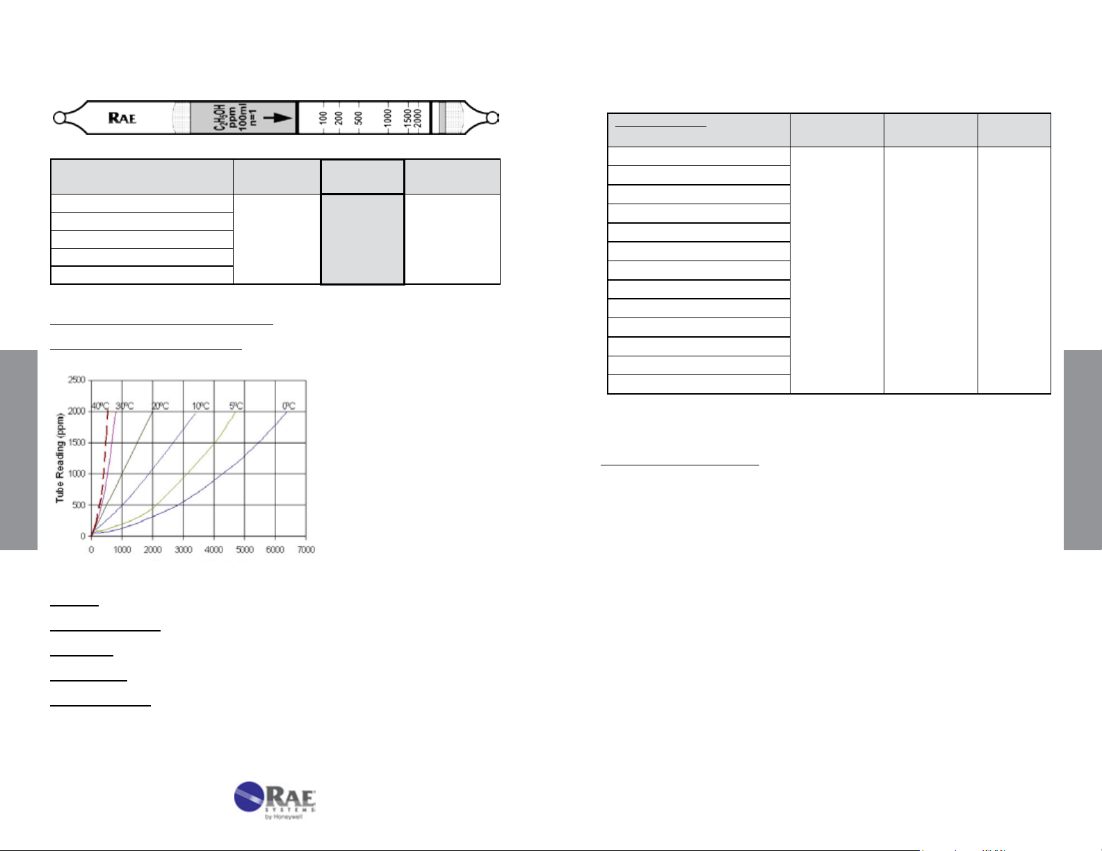
Ethanol C2H5OH No. 10-141-30
Ethanol C2H5OH (continued) No. 10-141-30
Extended
Range
Range (ppmv) 50-200
No. of Pump Strokes
Sample Volume (mL)
Sample Time (min)
Correction Factor
#
This CF only applies between 50-200 ppm; for higher concentrations use one stroke.
Precision (Relative Standard Deviation)*: ≤±20%
Linearity with No. of Pump Strokes: r2 = 0.87
#
2 1
200 100 Do not extend
2 x 3 3
#
0.5
Standard
Range
100 - 2000
1
Data SheetS
Extended
Range
Cross-sensitivity:
Substance
Methanol 1000 1000 1.0
Isopropanol
tert-Butanol
Methyl mercaptan
H
S
2
CH
4
CO
2
CO
NH
3
NO
Benzene
n-Hexane
Ethyl acetate
Data based on RAE Systems pumps and tubes used in standard range.
*
** Faint brown color over entire tube, but no effect on ethanol reading.
Other Possible Interferences: Other alcohols and mercaptans.
Concentration
(ppmv)
1000 750 1.3
1000 1300 0.77
500 300 1.7
100 0 -
25000 0 -
5000 0 -
1000 0 -
400 0 -
100 130 0.77
100 0 -
100 0 -
1000 0** -
Apparent
Reading*
Correction
Factor
Data SheetS
True concentration (ppm)
Humidity: No effect 0-95% RH
Temperature Range: 0 - 40°C (32 - 104°F)
Storage Life: 2 years in darkness at 5 - 25°C (40 - 77°F). Refrigeration preferred.
Color Change: Orange Yellow → Pale Green
Reaction Principle: C
OH + Cr(VI) + H2SO4 → Cr(III) + Oxidation Products
2H5
Continued on next page
52
www.raesystems.com
53
Page 29

Formaldehyde HCHO No. 10-121-05
Gasoline CnHm No. 10-138-30
Extended
Range
Range (ppmv) 0.1 - 5 0.8 - 40
No. of Pump Strokes 5 1
Sample Volume (mL) Do not extend 500 100
Sample Time (min) 5 x 2 2
Correction Factor 1 7.5
Standard
Range
Precision (Relative Standard Deviation)*: ≤±20%
2
Linearity with No. of Pump Strokes: r
> 0.995
Humidity: 0 - 95% RH
% RH <5% 30% 50% 80%
Corr. Factor 1.0 0.85 0.8 0.75
Temperature Range: 0 - 40°C (32 - 104°F)
Temp (°C/°F) 0/32 10/50 20/68 30/86 40/104
Corr. Factor 1.3 1.1 1.0 0.9 0.8
Storage Life: 2 years in darkness at 5 °C (40 - 77°F). Refrigeration preferred.
Color Change: Yellow → Reddish brown
Reaction Principle: 3HCHO + (NH
H
+ Base → Phosphate (dye color change)
3PO4
Data SheetS
Cross-sensitivity:
Substance
Acetaldehyde 3 3
Propionaldehyde 3 3
Acetone 3 Entire tube
Methyl ethyl ketone 3 Entire tube
CH
4
CO 500 0
CO
2
H
S 100 0
2
SO
2
Hexane 2000 0
Toluene 100 0
Isobutylene 100 0.5
Isopropanol 2000 0
Phenol 25 0
Styrene 20 0
* Data based on RAE Systems pumps and tubes used in standard range.
#
Faint brown color over entire stain length. 100 ppm gives stronger color.
Note: In dry air the background color may change: read only reddish-brown color.
OH)3 • H3PO4 → H3PO4 + 3H2C=NOH + 3H2O
2
Concentration
(ppmv)
25000 0
1000 0
100 0
Apparent
Reading*
#
#
Extended
Range
Extended
Range
Range (ppmv) 15 - 500
No. of Pump Strokes
Sample Volume (mL)
Sample Time (min)
Correction Factor
4 2 1
400 200 100
4 x 2 2 x 2 2
0.45 1 2.5
Standard
Range
30 - 1000
Extended
Range
60 - 2000
Precision (Relative Standard Deviation)*: ≤±20%
Linearity with No. of Pump Strokes: r
2
= 0.999
Humidity: No effect 5 - 95% RH.
Temperature Range: 0 - 40°C (32 - 104°F)
Temp (°C/°F) 0/32 10/50 22/72 40/104
Corr. Factor 1.6 1.24 1.0 0.83
Storage Life: 2 years in darkness at 5 - 25°C(40 - 77°F). Refrigeration preferred.
Color Change: Orange → Dark Green
Reaction Principle: Prelayer removes humidity
+ K2Cr2O7 + H2SO4 → Cr3+ + Oxidation Products
C
nHm
Cross-sensitivity:
Substance
CH
4
CO
H2S
SO
2
Acetone
Ethanol
Butane
Isopar L
Toluene
Benzene
* Data based on RAE Systems pumps and tubes used in standard range.
Note:
The tube is calibrated using heptane as a standard for gasoline.
Concentration
(ppmv)
25000 0
500 0
100 30
500 0
1000 20
1000 20
1000 Entire tube
500 115
200 80
500 900
Apparent
Reading*
Data SheetS
54
www.raesystems.com
55
Page 30

Total Hydrocarbons HC No. 10-110-30
Hydrogen Chloride HCl No. 10-108-09
Extended
Range
Standard
Range
Extended
Range (ppmv) 25 - 500 50 - 1000 100-2000
No. of Pump Strokes 4 2 1
Sample Volume (mL) 400 200 100
Sample Time (min) 4 x 2 2 x 2 2
Correction Factor 0.5 1 2
Precision (Relative Standard Deviation)*: ≤±20%
2
Linearity with No. of Pump Strokes: r
= 0.994
Humidity: No effect 5 - 100% RH
Temperature Range: 0 - 40°C (32 - 104°F)
Temp (°C/°F) 0/32 10/50 25/77 40/104
Corr. Factor 1.2 1.1 1.0 0.85
Storage Life: 2 years in darkness at 5 - 25°C (40 - 77°F). Refrigeration preferred.
Color Change: Yellow-Orange → Green
Reaction Principle: HC + Cr(VI) + H2SO4 → Cr(III) + Oxidation Products
Cross-sensitivity:
Substance
Concentration
(ppmv)
Apparent Reading* Corr.
Factor
Methane 25000 0 Ethylene 100 165 0.6
Data SheetS
Propane 100 Entire tube faint Isobutane 100 100 1.0
n-Pentane 500 700 0.7
n-Hexane 1200 870 1.4
n-Heptane 1000 525 1.9
n-Octane 400 103 3.9
n-Decane 1000 500 2.0
Benzene 500 Unclear endpoint Toluene 1000 110 9
Xylene 1000 60 17
Isobutylene 1000 20 50
Acetone 10000 60 170
Isopropanol 1000 <20 >50
Ethyl Acetate 1000 <20 >50
H2S 1000 250 4.0
* Data based on RAE Systems pumps and tubes used in standard range.
Other Possible Interferences: No response to 3000 ppm CO, 300 ppm NH3, or 200 ppm SO2.
Range
Extended
Range
Range (ppmv) 0.5 - 10
No. of Pump Strokes
Sample Volume (mL)
Sample Time (min)
Correction Factor
2 1 0.5
200 100 50
2 x 1 1 0.5
0.5 1 2
Standard
Range
1 - 20
Extended
Range
2 - 40
Precision (Relative Standard Deviation)*: ≤±20%
2
Linearity with No. of Pump Strokes: r
= 0.999
Humidity: Must be used @ <5% RH. Reading drops sharply above 5% RH.
Temperature Range: No effect between 0 - 40°C (32 - 104°F) at <5%RH.
Storage Life: 2 year in darkness at 5 - 25°C (40 - 77°F). Refrigeration preferred.
Color Change: Yellow → Pink
Reaction Principle: HCl + Base → Chloride Salt + H
Cross-sensitivity:
Substance
CO
CO
2
S
H
2
SO
2
NO
NO
2
NH
3
HF
Cl
2
CH
4
Hexane
Toluene
* Data based on RAE Systems pumps and tubes used in standard range.
Other Possible Interferences: Other acid vapors; amines and other bases.
Concentration
(ppmv)
15,000 0
8,000 0
800 0
200 0
100 0
200 20
100 0
25 15
10 0
25,000 0
2400 0
400 0
Apparent
Reading*
O (dye color change)
2
Data SheetS
56
www.raesystems.com
57
Page 31

Hydrogen Chloride HCl No.10-108-10
Hydrogen Chloride HCl No. 10-108-22
Extended
Range
Range (ppmv) 0.5 - 10
Standard
Range
1 - 20
No. of Pump Strokes 2 1 0.5
Sample Volume (mL) 200 100 50
Sample Time (min) 2 x 1 1 0.5
Correction Factor 0.5 1 2
Precision (Relative Standard Deviation)*: ≤±20%
Linearity with No. of Pump Strokes: r
2
= 0.999
Humidity: Calibrated at 50% RH and 23 °C (73 °F).
% Relative Humidity < 5% 30% 50% 70% 90%
Correction Factor @ 10 ppmv 0.7 0.8 1.0 1.1 2.7
Temperature Range: No effect between 0 - 40°C (32 - 104°F) at <5% RH.
Storage Life: 2 years in darkness at 5 - 25°C (40 - 77°F). Refrigeration preferred.
Color Change: Yellow → Pink
Reaction Principle: Pretube reduces humidity
Data SheetS
Cross-sensitivity:
Substance
HCl + NaOH → NaCl + H
Concentration
(ppmv)
Apparent
Reading*
O (dye color change)
2
CO 15,000 0
CO
2
8,000 0
H2S 800 0
SO
2
200 0
NO 100 0
NO
NH
2
3
200 20
100 0^
HF 25 15
Cl
CH
2
4
10 >20
25,000 0
Hexane 2400 0
Toluene 400 0
* Data based on RAE Systems pumps and tubes used in standard range.
^Interferes in mixtures
Other Possible Interferences: Other acid vapors; amines and other bases.
Extended
Range
2 - 40
Extended
Range
Range (ppmv) 10-250
No. of Pump Strokes
Sample Volume (mL)
Sample Time (min)
Correction Factor
2 1 0.5
200 100 50
2 x 1.5 1.5 1.0
0.5 1 2.0
Standard
Range
20-500
Extended
Range
40-1000
Precision (Relative Standard Deviation)*: ≤±20%
2
Linearity with No. of Pump Strokes: r
> 0.995
Humidity: No effect 5-95% RH.
Temperature Range: No effect 0 - 40°C (32 - 104°F); at -20°C, the response
is reduced by about 5%.
Storage Life: 2 years in darkness at 5 °C (40°F). Refrigeration required.
Color Change: Yellow → Red
Reaction Principle: HCl + Base
Cross-sensitivity:
Substance
CH
4
CO
CO
2
S
H
2
SO
2
NO
NO
2
NH
3
HF
Cl
2
Hexane
Toluene
* Data based on RAE Systems pumps and tubes used in standard range.
→ Chloride (dye color change)
Concentration
(ppmv)
Apparent
Reading*
25000 0
500 0
1000 0
100 0
1000 0
200 0
100 0
100 0
100 0
200 0
2000 0
2000 0
Data SheetS
58
www.raesystems.com
59
Page 32

Hydrogen Cyanide HCN No. 10-126-10
Hydrogen Fluoride HF No. 10-105-10
Extended
Range
Range (ppmv) 1.25 - 30
No. of Pump Strokes
Sample Volume (mL)
Sample Time (min)
Correction Factor
4 2 1
400 200 100
4 x 2.5 2 x 2.5 2.5
0.4 1 2
Standard
Range
2.5 - 60
Extended
Precision (Relative Standard Deviation)*: ≤±20%
Linearity with No. of Pump Strokes: r2 >0.999
Humidity: 5% - 95%RH
% Relative Humidity < 5% 10% 50% 95%
Correction Factor @ 10 ppmv 1.0 1.0 1.2 1.4
Temperature Range: No effect 0 - 40°C (32 - 104°F)
Storage Life: 1 year in darkness at 5 - 25°C (40 - 77°F). Refrigeration preferred.
Color Change: Yellow → Red (ignore light orange color formed in clean air)
Reaction Principle: 2HCN + HgCl
→ Hg(CN)2 + 2HCl
2
HCl + Base → Chloride Salt + H2O (dye color change)
Data SheetS
Cross-sensitivity:
Substance
H
2
CH
4
CO
S
H
2
HCl
SO
2
NH
3
CO
2
* Data based on RAE Systems pumps and tubes used in standard range.
#
Measured in dry gas; at >20% RH, no response is observed by these gases.
Concentration
(ppmv)
2000 0
25000 0
300 0
100 <1
100 <1
20 20
50 0
5000 0
Apparent
Reading*
#
#
#
Note: A light orange color may form when drawing in air with no HCN present. This
color can be ignored and does not affect true HCN readings, which form a bright
pinkish-red color. The color boundary is sharp in ambient, humid air and somewhat
diffuse in very dry air.
Range
5 - 120
Extended
Range
Range (ppmv) 0.25 - 10
No. of Pump Strokes
Sample Volume (mL)
Sample Time (min)
Correction Factor
8 4 2
800 400 200
8 x 0.5 4 x 0.5 2 x 0.5
0.4 1 1.6
Standard
Range
0.5 - 20
Extended
Range
1 - 40
Precision (Relative Standard Deviation)*: ≤±20%
Linearity with No. of Pump Strokes: r
2
= 0.98
Humidity: Calibrated at 50% RH and 23°C (73°F).
% Relative Humidity 30% 40% 50% 60% 70% 80% 90%
Correction Factor 0.3 0.4 1.0 1.3 1.6 2.0 2.6
Temperature Range: No effect 10 - 30°C (50 - 86°F) at constant 41% RH.
Storage Life: 2 years in darkness at 5 - 25°C (40 - 77°F). Refrigeration Preferred.
Color Change: Beige → Purple
Reaction Principle: HF + NaOH → NaF + H
Cross-sensitivity:
Substance
Concentration
(ppmv)
O
2
Apparent
Reading*
CO 250 0
CO
2
NH
3
NO
S
H
2
SO
2
CH
4
HCl
Cl
2
* Data based on RAE Systems pumps and tubes used in standard range.
#
Pink color over entire tube length.
^ May interfere in mixtures.
50000 0
300 0^
100 0
800 0
200 0
25000 0
4 entire tube
15 entire tube
#
#
Other Possible Interferences: Other acid vapors; amines and other bases. No
effect of 100 ppm toluene or 2400 ppm hexane.
Data SheetS
60
www.raesystems.com
61
Page 33

Hydrogen Sulde H
S No. 10-103-04
2
Hydrogen Sulde H
S No. 10-103-05
2
Extended
Range
Range (ppmv) 0.1 - 1.5
No. of Pump Strokes
Sample Volume (mL)
Sample Time (min)
Correction Factor
2 1 0.5
200 100 50
2 x 1.5 1.5 1
0.5 1 2
Standard
Range
0.2 - 3
Precision (Relative Standard Deviation)*: ≤±12%
2
Linearity with No. of Pump Strokes: r
= 0.999
Humidity: Tubes must be used @ <5% RH. Reading drops sharply above 5% RH.
Temperature Range: No effect between 0 - 40°C (32 - 104°F).
Storage Life: 1 year in darkness at 5 - 25°C (40 - 77°F). Refrigeration preferred.
Color Change: Pale orange → Pink
Reaction Principle: H2S + HgCl2 → Mercury sulde product + HCl
HCl + Base → Chloride Salt + H2O (dye color change)
Cross-sensitivity:
Data SheetS
Substance
Concentration
(ppmv)
Apparent
Reading*
Methyl mercaptan 2 0.4
Butyl mercaptan
NH
3
NO
2
SO
2
CS
2
CO
Hexane
Isobutylene
Toluene
* Data based on RAE Systems pumps and tubes used in standard range.
^ Reduces response when mixed with H
2 0.3
100 0
5 0
100 0
100 0
250 0
100 0
100 0^
100 0
S.
2
Other Possible Interferences: HCl and other acids and bases.
Extended
Range
0.4 - 6
Extended
Range
Standard
Range
Extended
Range
Range (ppmv) 0.1 - 1.5 0.2 - 3 0.4 - 6
No. of Pump Strokes 2 1 0.5
Sample Volume (mL) 200 100 50
Sample Time (min) 2 x 2 2 1
Correction Factor 0.5 1 2
Precision (Relative Standard Deviation)*: ≤±12%
2
Linearity with No. of Pump Strokes: r
= 0.999
Humidity: No effect between 5 - 90% RH.
Temperature Range: No effect between 0 - 40°C (32 - 104°F).
Storage Life: 1 year in darkness at 5 - 25°C (40 - 77°F). Refrigeration preferred.
Color Change: Pale orange → Pink
Reaction Principle: Pretube eliminates humidity
S + HgCl2 → Mercury sulde product + HCl
H
2
HCl + Base → Chloride Salt + H
Cross-sensitivity:
Substance
Concentration
(ppmv)
Methyl mercaptan 3 0
Butyl mercaptan 3 0
NH
NO
SO
CS
3
2
2
2
100 0
5 0
100 0
100 0
O (dye color change)
2
Apparent
Reading*
#
#
CO 250 0
Hexane 100 0
Isobutylene 100 0^
Toluene 100 0
* Data based on RAE Systems pumps and tubes used in standard range.
#
Interferes at higher concentrations.
^ Reduces response when mixed with H2S.
Other Possible Interferences: Acids and bases.
Data SheetS
62
www.raesystems.com
63
Page 34

Hydrogen Sulde H
S No. 10-103-06
2
Hydrogen Sulde H
S No. 10-103-10
2
Extended
Range
Range (ppmv) 0.25 – 1.75
No. of Pump Strokes
Sample Volume (mL)
Sample Time (min)
Correction Factor
2 1 0.5
200 100 50
2 x 1.5 1.5 1
0.25 0.5 1
Extended
Range
0.5 – 3.5
Precision (Relative Standard Deviation)*: ≤±12%
Humidity: Tubes must be used @ <5% RH. Reading drops sharply above 5% RH.
Temperature Range: No effect between 0 - 40°C (32 - 104°F).
Storage Life: 1 year in darkness at 5 - 25°C (40 - 77°F). Refrigeration preferred.
Color Change: Pale orange → Pink
Reaction Principle: H
Cross-sensitivity:
Substance
Methyl mercaptan 2 0.2
Data SheetS
Butyl mercaptan
NH
3
NO
2
SO
2
SO
2
CS
2
CO
Hexane
Isobutylene
Toluene
* Data based on RAE Systems pumps and tubes used in standard range.
#
Forms orange color over entire tube but pink H2S reading is unaffected in mixtures.
^ Reduces response when mixed with H2S.
S + HgCl2 → Mercury sulde product + HCl
2
HCl + Base → Chloride Salt + H
Concentration
(ppmv)
2
Apparent
Reading*
2 0.15
100 0
5 0
100 0
2000 0
100 0
250 0
100 0
100 0^
100 0
O (dye color change)
#
Other Possible Interferences: HCl and other acids and bases.
Standard
Range
1 - 7
Extended
Range
Standard
Range
Extended
Range
Range (ppmv) 1.25 - 30 2.5 - 60 5 - 120
No. of Pump Strokes 2 1 0.5
Sample Volume (mL) 200 100 50
Sample Time (min) 2 x 1.5 1.5 1
Correction Factor 0.5 1 2
Precision (Relative Standard Deviation)*: ≤±12%
2
Linearity with No. of Pump Strokes: r
= 0.998
Humidity: No effect 5 - 85% RH
Temperature Range: 0 - 40°C (32 - 104°F)
Temp (°C/°F) 0/32 10/50 25/77 40/104
Corr. Factor 0.95 0.95 1.0 1.2
Storage Life: 1 year in darkness at 5 - 25°C (40 - 77°F). Refrigeration preferred.
Color Change: White → Light Brown
Reaction Principle: H
Cross-sensitivity:
Substance
H
2
S + Pb(OAc)2 → PbS + 2HOAc
2
Concentration
(ppmv)
100% 0^
Apparent
Reading*
CO 250 0
CH
4
NH
3
NO
2
SO
2
SO
2
CS
2
Methyl mercaptan 100 0
25000 0
300 0
200 0
20 0
1800 0
100 0
‡
†
#
Diethyl sulde 100 0
Hexane 100 0
Isobutylene 100 0^
Toluene 100 0
* Data based on RAE Systems pumps and tubes used in standard range.
^ No effect in mixtures.
‡
Interferes in mixtures; may result in transient light brown H2S response.
†
Interferes in mixtures; high SO
#
Concentrations in the high % range leave a yellow color over the entire tube.
concentrations suppress H
2
S response.
2
Data SheetS
64
www.raesystems.com
65
Page 35

Hydrogen Sulde H
S No. 10-103-12
2
Hydrogen Sulde H
S No. 10-103-15
2
Extended
Range
Range (ppmv) 0 - 75
No. of Pump Strokes
Sample Volume (mL)
Sample Time (min)
Correction Factor
2 1 0.5
200 100 50
2 x 1.5 1.5 1
0.5 1 2
Standard
Range
0 - 150
Precision (Relative Standard Deviation)*: ≤±12%
Linearity with No. of Pump Strokes: r
2
= 0.999
Humidity: No effect 5 - 85% RH
Temperature Range: 0 - 40°C (32 - 104°F)
Temp (°C/°F) 0/32 10/50 24/75 40/104
Corr. Factor 0.88 0.96 1.0 1.1
Storage Life: 2 years in darkness at 5 - 25°C (40 - 77°F). Refrigeration preferred.
Color Change: White → Brown
Reaction Principle: H
Cross-sensitivity:
Data SheetS
Substance
S + Pb(OAc)2 → PbS + 2HOAc
2
Concentration
(ppmv)
Apparent
Reading*
CO 250 0
CH
4
NH
3
NO
2
CS
2
Methyl mercaptan
Diethyl sulde
Isobutylene
Toluene
* Data based on RAE Systems pumps and tubes used in standard range.
‡
Interferes in mixtures; may result in transient light brown H2S response.
#
No effect in mixtures. Concentrations in the high % range leave a yellow color over the
entire tube.
25000 0
100 0
200 0
100 0
1000 0
100 0
100 0
100 0
‡
#
Extended
Range
0 - 300
Extended
Range
Range (ppmv) 5 - 60
No. of Pump Strokes
Sample Volume (mL)
Sample Time (min)
Correction Factor
2 1 0.5
200 100 50
2 x 1.5 1.5 1
0.5 1 2
Standard
Range
10 - 120
Extended
Range
20 - 240
Precision (Relative Standard Deviation)*: ≤±12%
Linearity with No. of Pump Strokes: r
2
= 0.999
Humidity: No effect 5 - 85% RH
Temperature Range: 0 - 40°C (32 - 104°F)
Temp (°C/°F) 0/32 10/50 24/75 40/104
Corr. Factor 0.88 0.96 1.0 1.1
Storage Life: 2 years in darkness at 5 - 25°C (40 - 77°F). Refrigeration preferred.
Color Change: White → Brown
Reaction Principle: H
Cross-sensitivity:
Substance
S + Pb(OAc)2 → PbS + 2HOAc
2
Concentration
(ppmv)
Apparent
Reading*
CO 250 0
CH
4
NH
3
NO
2
CS
2
Methyl mercaptan
Diethyl sulde
Isobutylene
Toluene
* Data based on RAE Systems pumps and tubes used in standard range.
‡
Interferes in mixtures; may result in transient light brown H2S response.
#
No effect in mixtures. Concentrations in the high % range leave a yellow color over the
entire tube.
25000 0
100 0
200 0
100 0
1000 0
100 0
100 0
100 0
‡
#
Data SheetS
66
www.raesystems.com
67
Page 36

Hydrogen Sulde H
S No. 10-103-18
2
Hydrogen Sulde H
S No. 10-103-20
2
Extended
Range
Standard
Range
Range (ppmv) 12.5 - 125 25 - 250 50 - 500
No. of Pump Strokes 2 1 0.5
Sample Volume (mL) 200 100 50
Sample Time (min) 2 x 1 1 1
Correction Factor 0.5 1 2
Precision (Relative Standard Deviation)*: ≤±12%
2
Linearity with No. of Pump Strokes: r
= 0.999
Humidity: No effect 5 - 85% RH
Temperature Range: 0 - 40°C (32 - 104°F)
Temp (°C/°F) 0/32 10/50 23/73 40/104
Corr. Factor 0.9 0.9 1.0 1.1
Storage Life: 2 years in darkness at 5 - 25°C (40 - 77°F). Refrigeration preferred.
Color Change: White → Brown
Reaction Principle: H2S + Pb(OAc)2 → PbS + 2HOAc
Cross-sensitivity:
Data SheetS
Substance
Concentration
(ppmv)
Apparent
Reading*
CO 250 0
CH
4
NH
3
NO
2
CS
2
Methyl mercaptan
Diethyl sulde
Isobutylene
Toluene
* Data based on RAE Systems pumps and tubes used in standard range.
‡
Interferes in mixtures; may result in transient brown H2S response.
#
Concentrations in the high % range leave a yellow color over the entire tube.
25000 0
100 0
200 0
100 0
500 0
100 0
100 0
100 0
‡
#
Extended
Range
Extended
Range
Range (ppmv) 25 - 400
No. of Pump Strokes
Sample Volume (mL)
Sample Time (min)
Correction Factor
2 1 0.5
200 100 50
2 x 2 2 1.5
0.5 1 2
Standard
Range
50 - 800
Extended
Range
100 - 1600
Precision (Relative Standard Deviation)*: ≤±10%
2
Linearity with No. of Pump Strokes: r
= 0.989
Humidity: 80% RH reduces the reading by about 10% compared to dry air
Temperature Range: 0 - 40°C (32 - 104°F)
Temp (°C/°F) 0/32 10/50 25/77 40/104
Corr. Factor 1.0 1.0 1.0 1.2
Storage Life: 2 years in darkness at 5 - 25°C (40 - 77°F). Refrigeration preferred.
Color Change: White → Dark Brown
Reaction Principle: H2S + Pb(OAc)2 → PbS + 2HOAc
Cross-sensitivity:
Substance
Concentration
(ppmv)
Apparent
Reading*
CO 250 0
CH
4
NH
3
NO
2
SO
2
CS
2
Methyl mercaptan
Diethyl sulde
Hexane
Isobutylene
Toluene
* Data based on RAE Systems pumps and tubes used in standard range.
‡
Interferes in mixtures; may result in transient brown H2S response.
25000 0
300 0
200 0
20 0
100 0
500 <50
1000 0
100 0
100 0
100 0
‡
Data SheetS
68
www.raesystems.com
69
Page 37

Hydrogen Sulde H
S No. 10-103-30
2
Hydrogen Sulde H
S No. 10-103-40
2
Extended
Range
Range (ppmv) 50 - 1000
No. of Pump Strokes
Sample Volume (mL)
Sample Time (min)
Correction Factor
2 1 0.5
200 100 50
2 x 2 2 1.5
0.5 1 2
Standard
Range
100 - 2000
200 - 4000
Precision (Relative Standard Deviation)*: ≤±10%
Linearity with No. of Pump Strokes: r
2
= 0.999
Humidity: No effect 5 - 85% RH
Temperature Range: 0 - 40°C (32 - 104°F)
Temp (°C/°F) 0/32 10/50 25/77 40/104
Corr. Factor 0.88 0.93 1.0 1.2
Storage Life: 2 years in darkness at 5 - 25°C (40 - 77°F). Refrigeration preferred.
Color Change: White → Black
Reaction Principle: H
Cross-sensitivity:
Substance
Data SheetS
S + Pb(OAc)2 → PbS + 2HOAc
2
Concentration
(ppmv)
Apparent
Reading*
CO 250 0
CH
4
NH
3
NO
2
SO
2
CS
2
Hexane
Isobutylene
Toluene
* Data based on RAE Systems pumps and tubes used in standard range.
‡
Interferes in mixtures; may result in transient brown H2S response.
25000 0
300 0
200 0
20 0
100 0
100 0
100 0
100 0
‡
Other Possible Interferences: No response to mercaptans and suldes.
Extended
Range
Extended
Range
Range (ppmv) 0.05 - 1%
No. of Pump Strokes
Sample Volume (mL)
Sample Time (min)
Correction Factor
2 1 0.5
200 100 50
2 x 2 2 1.5
0.5 1 2
Standard
Range
0.1 - 2%
Extended
Range
0.2 - 4%
Precision (Relative Standard Deviation)*: ≤±10%
Linearity with No. of Pump Strokes: r
2
= 0.998
Humidity: No effect 5 - 85% RH
Temperature Range: 0 - 40°C (32 - 104°F)
Temp (°C/°F) 0/32 18/64 25/77 40/104
Corr. Factor 1.2 1.1 1.0 1.0
Storage Life: 2 years in darkness at 5 - 25°C (40 - 77°F). Refrigeration preferred.
Color Change: Light Blue → Black
Reaction Principle: H
Cross-sensitivity:
Substance
S + CuSO4 → CuS + H2SO
2
Concentration
(ppmv)
4
Apparent
Reading*
CO 3000 0
CH
4
NO
NO
2
NH
3
SO
2
Methyl mercaptan
Diethyl sulde
Isobutylene
Toluene
Hexane
* Data based on RAE Systems pumps and tubes used in standard range.
#
Concentrations in the high % range leave a yellow color over the entire tube.
25000 0
100 0
200 0
300 0
20 0
0.1% 0.1%
1000 0
100 0
100 0
1200 0
#
Other Possible Interferences: High Concentrations of ammonia; NO2 in mixtures.
No response to CS2.
Data SheetS
70
www.raesystems.com
71
Page 38

Hydrogen Sulde H
S No. 10-103-50
2
Mercaptans RSH No. 10-129-20
Extended
Range
Extended
Range
Range (ppmv) 0.5 - 10% 1 - 20% 2 - 40%
No. of Pump Strokes 2 1 0.5
Sample Volume (mL) 200 100 50
Sample Time (min) 2 x 1.5 1.5 1.5
Correction Factor 0.25 0.5 1
Precision (Relative Standard Deviation)*: ≤±10%
2
Linearity with No. of Pump Strokes: r
= 0.999
Humidity: No effect 5 - 85% RH
Temperature Range: 0 - 40°C (32 - 104°F)
Temp (°C/°F) 0/32 10/50 18/64 40/104
Corr. Factor 0.75 1.0 1.0 1.0
Storage Life: 2 years in darkness at 5 - 25°C (40 - 77°F). Refrigeration preferred.
Color Change: Light Blue → Black
Reaction Principle: H
Data SheetS
Cross-sensitivity:
Substance
S + CuSO4 → CuS + H2SO
2
Concentration
(ppmv)
4
Apparent
Reading*
CO 250 0
CO
2
NO
NH
3
CH
4
SO
2
Isobutylene
Hexane
Benzene
Toluene
* Data based on RAE Systems pumps and tubes used in standard range.
5% 0
100 0
10% 3.5% (blue)
2.5% 0
10 0
100 0
100 0
100 0
100 0
Other Possible Interferences: Mercaptans. No response to suldes.
Note: Time measurement to exactly 2 minutes for best accuracy.
Standard
Range
Extended
Range
Standard
Range
Extended
Range
Range (ppmv) 2.5 - 60 5 - 120 10 - 240
No. of Pump Strokes 2 1 0.5
Sample Volume (mL) 200 100 50
Sample Time (min) 2 x 2.0 2.0 1.0
Correction Factor 0.5 1 2.1
Precision (Relative Standard Deviation)*: ≤±20%
2
Linearity with No. of Pump Strokes: r
= 0.999
Humidity: No effect between 5 - 90% RH.
Temperature Range: No effect between 0 - 40°C (32 - 104°F)
Storage Life: 1 year in darkness at 5 - 25°C (40 - 77°F). Refrigeration preferred.
Color Change: White → Yellow
Reaction Principle: 2RSH + PdSO
Cross-sensitivity:
Substance
H
S 500 0
2
CO
Diethyl sulde
Ethyl mercaptan
Propyl mercaptan
Butyl mercaptan
Acetylene
Ethylene
* Data based on RAE Systems pumps and tubes used in standard range.
1
Up to 500 ppm H2S is trapped in the pretreatment layer.
2
Gray through the entire tube, will not affect RSH reading in mixtures.
3
Interferes in mixtures; may result in high response.
4
Pale brown through the entire tube, will not affect RSH reading in mixtures.
5
Light peach through the entire tube, will not affect RSH reading in mixtures.
→ (RS)2Pd + H2SO
4
Concentration
(ppmv)
500 0
5000 30
4
Apparent
Reading*
1
2
3
60 60 1.0
60 60 1.0
60 29 2.0
2000 0
2000 0
4
5
Corr.
Factor
-
-
-
-
-
Data SheetS
72
www.raesystems.com
73
Page 39

Methyl Bromide CH3Br No. 10-131-10
Methyl Bromide CH3Br No. 10-131-30
Extended
Range
Range (ppmv) 0.5-9
No. of Pump Strokes
Sample Volume (mL)
Sample Time (min)
Correction Factor
4 2 1
400 200 100
4 x 3 2 x 3 3
0.48 1.0 2.1
Standard
Range
1-18
Extended
Precision (Relative Standard Deviation)*: ≤±20%
Linearity with No. of Pump Strokes: r
2
= 0.997
Humidity: No effect 5 - 100% RH
Temperature Range: 0 - 40°C (32 - 104°F)
Temp (°C/°F) 0/32 10/40 25/77 40/104
Corr. Factor 1.5 1.3 1.0 0.95
Storage Life: 2 years in darkness at 5 - 25°C (40 - 77°F). Refrigeration preferred.
Color Change: White → Orange
Reaction Principle: Pre-tube : C H
Measurement Tube: Br2 + indicator dye → Orange product
Data SheetS
Cross-sensitivity:
Substance
Tetrachloroethylene 200 13
Trichloroethylene
Vinylidene Chloride
Vinyl Chloride
3-Chloro-2-Methylpropene
1,2-Dichloroethane
1,1,1- Trichloroethane
Cl
2
NO
NO
2
CH
4
CO
CO
2
* Data based on RAE Systems pumps and tubes used in standard range.
Other Possible Interferences: No response to 500 ppm propane, 100 ppm isobutylene or
1200 ppm hexane.
Br + K2Cr2O7 + H2SO4 → Br2 + Other Prods
3
Concentration
(ppmv)
100 4
200 47
200 5
200 4
200 0
50 4.5
10 21
500 0.6
570 1.0
25000 0
500 0
5000 0
Apparent Reading*
Range
2-36
Extended
Range
Range (ppmv) 10-150
No. of Pump Strokes
Sample Volume (mL)
Sample Time (min)
Correction Factor
2 1 0.5
200 100 50
2 x 2 2 2 x 0.5
0.43 1 2.2
Standard
Range
20-300
Precision (Relative Standard Deviation)*: ≤ ± 15%
Linearity with No. of Pump Strokes: 0.999
Humidity: No effect 0 - 90% RH
Temperature Range: 0 - 40°C (32 - 104°F)
Temp (°C/°F) 0/32 10/50 20/68 30/86 40/104
Corr. Factor 1.7 1.3 1.0 0.8 0.7
Storage Life: 2 years in darkness at <10°C. Refrigeration preferred.
Color Change: White → Orange-yellow
Reaction Principle: Pretube: 2CH
Measurement Tube: Br
Cross-sensitivity:
Substance
1,2-Dibromoethane 300 600
1,3-Dibromopropane 600 700
1,1,1-Tric h l oroe t hane 300 30
Trichloroethylene 80 15
Cl
2
Ethanol 10000 0
Ethyl acetate 10000 0
Acetone 10000 0
CH
4
CO
2
CO 500 0
H
S 500 0
2
SO
2
NO 460 0
NO
2
* Data based on RAE Systems pumps and tubes used in standard range.
Br + I2O5 + H2S2O7 → Br2
3
+ o-Tolidine → Orange-yellow product
2
Concentration
(ppmv)
80 63
25000 0
5000 0
100 0
110 0
Apparent Reading*
Extended
Range
40-600
Data SheetS
74
www.raesystems.com
75
Page 40

Methyl Ethyl Ketone C4H8O No. 10-113-20
Nitric Acid HNO3 No. 10-146-20
Extended
Range
Range (ppmv) 0.01 - 0.3%
No. of Pump Strokes
Sample Volume (mL)
Sample Time (min)
Correction Factor
6 3 1
600 300 100
6 x 2 3 x 2 2
0.5 1 3
Standard
Range
0.02 - 0.6%
Extended
Range
0.06 - 1.8%
Precision (Relative Standard Deviation)*: ≤±12%
2
Linearity with No. of Pump Strokes: r
= 0.996
Humidity: 85% RH increases the response by 15% compared to dry gas.
Temperature Range: 0 - 40°C (32 - 104°F)
Temp (°C/°F) 0/32 10/50 25/77 40/104
Corr. Factor 1.4 1.3 1.0 0.7
Storage Life: 2 years in darkness at 5 - 25°C (40 - 77°F). Refrigeration preferred.
Color Change: Orange → Black
Reaction Principle: CH
Cross-sensitivity:
Substance
Data SheetS
Acetone 0.4% 0.5% 0.8
Methyl propyl ketone 1.0% 0.7% 1.4
Methyl isobutyl ketone 1.0% 0.49% 2.0
CO 1.5% 0 CO
2
CH
4
NH
3
H2S 250 0.2% diffuse
Ethyl Acetate 1.0% >0.3% diffuse
Hexane 0.24% entire tube
Isobutylene 0.20% 0.5% 0.4
Toluene 400 0.3% diffuse
* Data based on RAE Systems pumps and tubes used in standard range.
# Faint black color. Ketones can be distinguished by their darker stains and sharp endpoints.
COCH2CH3 + Cr(VI) + H2SO4 → Cr(III) + Oxidation Prods.
3
Concentration
(ppmv)
1.5% 0 -
2.5% 0 -
5.0% >0.3% brown -
Apparent
Reading*
Factor
#
#
#
#
Other Possible Interferences: Other hydrocarbons.
Corr.
-
-
-
-
Extended
Range
Range (ppmv) 0. 5 -10 1-20 2- 40
No. of Pump Strokes 2 1 0.5
Sample Volume (mL) 200 100 50
Sample Time (min) 2 x 1 1 0.5
Correction Factor 0.46 1 2.1
Standard
Range
Extended
Range
Precision (Relative Standard Deviation)*: ≤ ± 20%
Linearity with No. of Pump Strokes: r
2
= 0.98
Humidity Range: 0 - 90% RH. Calibrated at 50% RH and 20°C (68°F)
% Relative Humidity 0% 30% 50% 70% 80% 90%
Correction Factor 0.7 0.8 1.0 1. 3 1.8 1.9
Temperature Range: 0 - 40°C (32 - 104°F)
Temp(°C/°F) 0/32 10/5 0 20/68 30/86 40/104
Corr. Factor 1. 3 1.2 1.0 0.9 0.8
Storage Life: 2 years in darkness at 5 - 25°C (40 - 77°F). Refrigeration preferred.
Color Change: Orange → Black
Reaction Principle: CH
Cross-sensitivity: Substance Concentration (ppmv) Apparent Reading*
HCl 10 14
Cl
2
HF 10 7
Acetic Acid saturated ≤2 (v. pale)
CO 250 0
CO
2
CH
4
NO 100 0
NO
2
H2S 60 0
SO
2
HCN 60 0
* Data based on RAE Systems pumps and tubes used in standard range.
HNO3 + Base → Dye color change
3
5 13
50000 0
25000 0
60 0
200 0
Other Possible Interferences: Other acids may give a positive response and
bases may give a negative response in mixtures. Headspace from 85% H
and H
give ≤1 ppm response because of their low volatility.
2SO4
3PO4
Data SheetS
76
www.raesystems.com
77
Page 41

Nitrogen Dioxide NO2 No. 10-117-10
Nitrogen Oxides NOX No. 10-109-20
(Separate Quantication)
Range (ppmv)
No. of Pump Strokes
Sample Volume (mL)
Sample Time (min)
Correction Factor
Extended
Range
Do Not Extend
Standard
Range
0.5-30
1
100
1.5
1
Extended
Range
Do Not Extend
Precision (Relative Standard Deviation)*: ≤±20%
Linearity with No. of Pump Strokes: Non-linear, do not extend
Humidity: No effect between 0-90%RH.
Temperature Range: No effect between 0 - 40°C (32 - 104°F)
Storage Life: 1 year in darkness at 5 - 25°C (40 - 77°F). Refrigeration preferred.
Color Change: White → Yellow
Reaction Principle: NO
Cross-sensitivity:
Substance
+ o-Tolidine → Nitrated yellow product
2
Concentration
(ppmv)
Apparent
Reading*
CO 3000 0
CO
SO
CH
H
2
2
4
S
2
Data SheetS
Acetone
Benzene
n-Hexane
Isobutylene
Toluene
Cl
2
NO
* Data based on RAE Systems pumps and tubes used in standard range.
˄
Cl2 results in light yellow stain.
#
NO results in orange stain.
200000 0
200 0
25000 0
100 0
10000 0
5 0
100 0
100 0
100 0
50 Entire tube
500 1
˄
#
Other Possible Interferences: Reducing gases.
Extended
Range
Standard
Range
Extended
Range
Range (ppmv) 0.5 - 25 1-50 2-100
No. of Pump Strokes 2 1 0.5
Sample Volume (mL) 200 100 50
Sample Time (min) 2 x 3 3 2.5
Correction Factor 0.5 1 2
Precision (Relative Standard Deviation)*: ≤±20%
2
Linearity with No. of Pump Strokes: r
= 0.997
Humidity: 100% RH reduces the response by about 20% vs. dry air
Temperature Range: 0 - 40°C (32 - 104°F)
Temp (°C/°F) 0/32 10/50 25/77 40/104
Corr. Factor 1.8 1.6 1.0 1.0
Storage Life: 1 year in darkness at 5 - 25°C (40 - 77°F). Refrigeration preferred.
Color Change: White → Yellow
Reaction Principle: NO + CrO
NO
+ o-Tolidine → Nitrated yellow product Meas. tube
2
Cross-sensitivity:
Substance
+ H2SO4 → NO2 Pre-tube
3
Concentration
(ppmv)
Apparent
Reading*
CO 3000 0
CO
2
SO
2
CH
4
S
H
2
Acetone
* Data based on RAE Systems pumps and tubes used in standard range.
10% 0
200 0
25000 0
100 0
10000 0
Other Possible Interferences: Reducing gases. No response to 5 ppm benzene.
No response to 1200 ppm hexane, 100 ppm isobutylene, or 100 ppm toluene.
Separate Quantication: Sampling without the pre-tube gives NO2 only. Using
the pre-tube gives the sum of NO + NO2. NO can be obtained by difference.
Data SheetS
78
www.raesystems.com
79
Page 42

Ozone O
No. 10-133-03
3
Phenol C6H5OH No. 10-139-05
Extended
Range
Range (ppmv)
Standard
Range
0.05 – 0.6
No. of Pump Strokes 5 1
Sample Volume (mL) Do not extend 500 100
Sample Time (min) 5 x 2 2
Correction Factor 1 3
Precision (Relative Standard Deviation)*: ≤±20%
2
Linearity with No. of Pump Strokes: r
= 0.990
Humidity: Calibration is based on approximately 50% relative humidity.
Temperature Range: 0 - 40°C (32 - 104°F)
Temp (°C/°F) 0/32 10/50 20/68 40/104
Corr. Factor 0.74 1.0 1.0 1.1
Storage Life: 1 year in darkness at 5 - 25°C (40 - 77°F). Refrigeration preferred.
Color Change: Blue → White
Reaction Principle: 2O
Cross-sensitivity:
Data SheetS
Substance
Cl
2
Cl
2
ClO
2
+ C16H10N2O
3
→ 2C8H5NO
2
2
Concentration
(ppmv)
<10 0
≥10 ~0.1
1 entire tube#
+ 2O
Apparent
Reading*
2
#
CO 100 0
CO
CH
SO
2
4
2
10,000 0
70,000 0
100 0
H2S 120 0
NO 5 0
NO
2
1 0
Isobutylene 100 0
*
Data based on RAE Systems pumps and tubes used in standard range.
#
Slight discoloration and unclear demarcation.
Other Possible Interferences: Bromine and other oxidants.
Extended
Range
0.15 – 1.8
Extended
Range
Range (ppmv) 0.5 - 11
No. of Pump Strokes
Sample Volume (mL)
Sample Time (min)
Correction Factor
4 2 1 0.5
400 200 100 50
4 x 1.5 2 x 1.5 1.5 1.0
0.45 1 2.4 7.2
Standard
Range
1 - 25
Extended
Range
Extended
Range
2.4 - 60 7 - 180
Precision (Relative Standard Deviation)*: ≤±20%
2
Linearity with No. of Pump Strokes: r
= 0.996
Humidity:
% Relative Humidity 10% 30% 50% 90%
Correction Factor 1.0 1.25 1.6 1.8
True concentration (ppm)
Temperature Range: 10 - 40°C (50 - 104°F)
Storage Life: 1.5 years in darkness at 5 - 25°C (40 - 77°F). Refrigeration preferred.
Color Change: Pale Yellow → Gray
Reaction Principle: C6H5OH + Ce(NH4)2(NO3)6 → Cerium-Phenol complex
Continued on next page
Data SheetS
80
www.raesystems.com
81
Page 43

Phenol C6H5OH (continued) No. 10-139-05
Phosphine PH3 No. 10-116-10
Cross-sensitivity:
Substance
H2S 100 0
NH
3
NO
NO
2
SO
2
CH
4
CO
2
CO
Formaldehyde (HCHO)
Acetone
Isopropanol
Isobutylene
n-Hexane
Benzene
Toluene
Styrene
Concentration
(ppmv)
500 0
400 0
400 0
200 0
25000 0
5000 0
500 0
500 0
2000 0
2000 0
100 0
2000 0
2000 0
2000 0
2000 0
Apparent
Reading*
* Data based on RAE Systems pumps and tubes used in standard range.
Data SheetS
Extended
Range
Range (ppmv) 2.5 - 25
No. of Pump Strokes
Sample Volume (mL)
Sample Time (min)
Correction Factor
4 2 1
400 200 100
4 x 1.5 2 x 1.5 1.5
0.5 1 1.7
Standard
Range
5 - 50
Extended
Range
10 - 100
Precision (Relative Standard Deviation)*: ≤±12%
2
Linearity with No. of Pump Strokes: r
= 0.997
Humidity: No effect 5 - 90% RH.
Temperature Range: 0 - 40°C (32 - 104°F)
Temp (°C/°F) 0/32 10/50 25/77 40/104
Corr. Factor 0.85 0.90 1.0 1.0
Storage Life: 1 year in darkness at 5 - 25°C (40 - 77°F). Refrigeration preferred.
Color Change: White → Yellow
Reaction Principle: 2PH3 + 6HgCl2 + 3H2O → Hg3P2•3HgCl2•3H2O + 6HCl
Cross-sensitivity:
Substance
S 50 28 (l. brown)
H
2
SO
2
NO
NH
3
CO
CO
2
CH
4
Hexane
Toluene
* Data based on RAE Systems pumps and tubes used in standard range.
Concentration
(ppmv)
200 0
100 0
100 0
100 0
50000 0
25000 0
1500 0
100 0
Apparent
Reading*
Data SheetS
82
Other Possible Interferences: Strongly reducing gases.
www.raesystems.com
83
Page 44

Phosphine PH3 No. 10-116-20
Phosphine PH
No. 10-116-25
3
Extended
Range
Range (ppmv) 12.5 - 250
No. of Pump Strokes
Sample Volume (mL)
Sample Time (min)
Correction Factor
2 1 0.5
200 100 50
2 x 1.5 1.5 1
0.5 1 2
Standard
Range
25 - 500
Precision (Relative Standard Deviation)*: ≤±12%
Linearity with No. of Pump Strokes: r
2
= 0.99
Humidity: No effect 5 - 80% RH.
Temperature Range: 0 - 40°C (32 - 104°F)
Temp (°C/°F) 0/32 10/50 24/75 40/104
Corr. Factor 0.85 0.95 1.0 1.15
Storage Life: 1 year in darkness at 5 - 25°C (40 - 77°F). Refrigeration preferred.
Color Change: White → Yellow
Reaction Principle: 2PH3 + 6HgCl2 + 3H2O → Hg3P2•3HgCl2•3H2O + 6HCl
Cross-sensitivity:
Data SheetS
Substance
H
S 50 35 (brown)
2
SO
2
NO
NH
3
CO
CO
2
CH
4
Hexane
Toluene
* Data based on RAE Systems pumps and tubes used in standard range.
Concentration
(ppmv)
200 0
100 0
100 0
250 0
50000 0
25000 0
1500 0
100 0
Apparent
Reading*
Other Possible Interferences: Strongly reducing gases.
Extended
Range
50 - 1000
Extended
Range
Range (ppmv) 25 - 500
No. of Pump Strokes
Sample Volume (mL)
Sample Time (min)
Correction Factor
2 1 0.5
200 100 50
2 x 1.5 1.5 1
0.5 1 2
Standard
Range
50 - 1000
Extended
Range
100 - 2000
Precision (Relative Standard Deviation)*: ≤±10%
Linearity with No. of Pump Strokes: r
2
= 1.000
Humidity: No effect 5 - 80% RH.
Temperature Range: No effect between 0-40°C (32 - 104°F)
Storage Life: 1 year in darkness at 5 - 25°C (40 - 77°F). Refrigeration preferred.
Color Change: White → Yellow
Reaction Principle: 2PH3 + 6HgCl2 + 3H2O → Hg3P2•3HgCl2•3H2O + 6HCl
Cross-sensitivity:
Substance
H
S 200 140
2
SO
2
NO
NH
3
CO
CO
2
CH
4
Hexane
Toluene
* Data based on RAE Systems pumps and tubes used in standard range.
‡
Interferes in mixtures; may result in transient light brown H2S response.
Concentration
(ppmv)
3940 0
100 0
100 0
250 0
50000 0
25000 0
1500 0
100 0
Apparent
Reading*
‡
Other Possible Interferences: Strongly reducing gases.
Data SheetS
84
www.raesystems.com
85
Page 45

Sulfur Dioxide SO2 No. 10-107-15
Sulfur Dioxide SO2 No. 10-107-20
Extended
Range
Range (ppmv) 1 - 15
No. of Pump Strokes
Sample Volume (mL)
Sample Time (min)
Correction Factor
4 2 1
400 200 100
4 x 2 2 x 2 2
0.5 1 2
Standard
Range
2 - 30
Extended
Precision (Relative Standard Deviation)*: ≤±12%
2
Linearity with No. of Pump Strokes: r
= 0.991
Humidity: No effect 5 - 90% RH.
Temperature Range: 0 - 40°C (32 - 104°F)
Temp (°C/°F) 0/32 10/50 24/75 40/104
Corr. Factor 1.1 1.1 1.0 1.1
Storage Life: 2 years in darkness at 5 - 25°C (40 - 77°F). Refrigeration preferred.
Color Change: Blue-green → Yellow
Reaction Principle: SO2 + 2NaOH → Na2SO3 + H2O (pH indicator change)
Cross-sensitivity:
Data SheetS
Substance
Concentration
(ppmv)
Apparent
Reading*
CO 15000 0
CO
2
NO
NH
3
H2S
PH
3
HF
CH
4
Hexane
Toluene
* Data based on RAE Systems pumps and tubes used in standard range.
#
Reduces reading in mixture.
50000 0
100 0
100 2 (blue)
2000 3 (blue)
30 0
50 0.5
25000 0
1500 0
400 0
#
Other Possible Interferences: Acid gases.
Range
4 - 60
Extended
Range
Range (ppmv) 2.5 - 50
No. of Pump Strokes
Sample Volume (mL)
Sample Time (min)
Correction Factor
2 1 0.5
200 100 50
2 x 2 2 1.5
0.5 1 2
Standard
Range
5 - 100
Extended
Range
10 - 200
Precision (Relative Standard Deviation)*: ≤±12%
Linearity with No. of Pump Strokes: r
2
= 0.999
Humidity: No effect 5 - 50% RH; 100% RH reduces the response by about 25%
Temperature Range: 0 - 40°C (32 - 104°F)
Temp (°C/°F) 0/32 10/50 25/77 40/104
Corr. Factor 1.2 1.0 1.0 1.0
Storage Life: 2 years in darkness at 5 - 25°C (40 - 77°F). Refrigeration preferred.
Color Change: Blue → Yellow
Reaction Principle: SO
Cross-sensitivity:
Substance
+ 2NaOH → Na2SO3 + H2O (pH indicator change)
2
Concentration
(ppmv)
Apparent
Reading*
CO 3000 0
CO
2
NO
NH
3
CH
4
S
H
2
Isobutylene
Hexane
Toluene
Acetone
* Data based on RAE Systems pumps and tubes used in standard range.
#
Reduces reading in mixture.
10% 0
100 0
300 0
25000 0
100 0
100 0
1200 0
100 0
10000 0
#
Other Possible Interferences: Acid gases.
Data SheetS
86
www.raesystems.com
87
Page 46

Sulfur Dioxide SO2 No. 10-107-25
Sulfur Dioxide SO2 No. 10-107-30
Extended
Range
Range (ppmv) 50 - 900
No. of Pump Strokes
Sample Volume (mL)
Sample Time (min)
Correction Factor
2 1 0.5
200 100 50
2 x 2 2 1.5
0.5 1 2
Standard
Range
100 - 1800
Extended
200 - 3600
Precision (Relative Standard Deviation)*: ≤±10%
Linearity with No. of Pump Strokes: r2 = 0.999
Humidity: No effect 5 - 85% RH.
Temperature Range: 0 - 40°C (32 - 104°F)
Temp (°C/°F) 0/32 10/50 25/77 40/104
Corr. Factor 1.1 1.0 1.0 1.0
Storage Life: 2 years in darkness at 5 - 25°C (40 - 77°F). Refrigeration preferred.
Color Change: Blue → Yellow
Reaction Principle: SO
Cross-sensitivity:
Data SheetS
Substance
+ 2NaOH → Na2SO3 + H2O (pH indicator change)
2
Concentration
(ppmv)
Apparent
Reading*
CO 3000 0
CO
2
NO
NH
3
CH
4
S
H
2
Hexane
Isobutylene
Toluene
* Data based on RAE Systems pumps and tubes used in standard range.
#
Reduces reading in mixture.
10% 0
100 0
300 0
25000 0
100 0
1200 0
100 0
100 0
#
Other Possible Interferences: Acid gases.
Range
Extended
Range
Extended
Range
Standard
Range
Range (ppmv) 50 - 1000 100 - 2000 200 - 4000
No. of Pump Strokes 2 1 0.5
Sample Volume (mL) 200 100 50
Sample Time (min) 2 x 1 1 1
Correction Factor 0.25 0.5 1
Precision (Relative Standard Deviation)*: ≤±10%
2
Linearity with No. of Pump Strokes: r
= 0.999
Humidity: No effect 5 - 50% RH; 100% RH reduces the response by about 40%
Temperature Range: 0 - 40°C (32 - 104°F)
Temp (°C/°F) 0/32 10/50 25/77 40/104
Corr. Factor 1.1 1.0 1.0 1.0
Storage Life: 2 years in darkness at 5 - 25°C (40 - 77°F). Refrigeration preferred.
Color Change: Blue → Yellow
Reaction Principle: SO
Cross-sensitivity:
Substance
+ 2NaOH → Na2SO3 + H2O (pH indicator change)
2
Concentration
(ppmv)
Apparent
Reading*
CO 3000 0
CO
2
NO
NH
3
CH
4
S
H
2
Hexane
Isobutylene
Toluene
* Data based on RAE Systems pumps and tubes used in standard range.
#
Reduces reading in mixture.
10% 0
100 0
300 0
25000 0
100 0
1200 0
100 0
100 0
#
Other Possible Interferences: Acid gases.
Data SheetS
88
www.raesystems.com
89
Page 47

Sulfur Dioxide SO2 No. 10-107-40
Toluene C7H8 No. 10-114-20
Extended
Range
Range (ppmv) 0.1 – 2.5%
No. of Pump Strokes
Sample Volume (mL)
Sample Time (min)
Correction Factor
2 1 0.5
200 100 50
2 x 2 2 1.5
0.5 1 2
Standard
Range
0.2 - 5%
Extended
0.4 - 10%
Precision (Relative Standard Deviation)*: ≤±10%
Linearity with No. of Pump Strokes: r2 = 0.999
Humidity: No effect 5 - 90% RH
Temperature Range: 0 - 40°C (32 - 104°F)
Temp (°C/°F) 0/32 10/50 25/77 40/104
Corr. Factor 1.15 1.0 1.0 1.0
Storage Life: 2 years in darkness at 5 - 25°C (40 - 77°F). Refrigeration preferred.
Color Change: Yellow → Green
Reaction Principle: SO2 + Cr(VI) + H2O → H2SO4 + Cr(III)
Cross-sensitivity:
Data SheetS
Substance
Concentration
(ppmv)
Apparent
Reading*
CO 3000 0
CO
2
NH
3
CH
4
S
H
2
Hexane
Isobutylene
Benzene
* Data based on RAE Systems pumps and tubes used in standard range.
#
Forms a bright yellow color and reduces reading in mixture.
5% 0
5% 2.3% #
2.5% 0
50 0
1500 0
2000 0
100 0
Other Possible Interferences: Reducing gases.
Range
Extended
Range
Range (ppmv) 5 - 150
No. of Pump Strokes
Sample Volume (mL)
Sample Time (min)
Correction Factor
2 1 0.5
200 100 50
2 x 2 2 1.5
0.5 1 2
Standard
Range
10 - 300
Extended
Range
20 - 600
Precision (Relative Standard Deviation)*: ≤±12%
Linearity with No. of Pump Strokes: r
2
= 0.994
Humidity: No effect 0 - 90% RH
Temperature Range: 0 - 40°C (32 - 104°F)
Temp (°C/°F) 0/32 10/50 25/77 40/104
Corr. Factor 1.2 1.0 1.0 1.1
Storage Life: 2 years in darkness at 5 - 25°C (40 - 77°F). Refrigeration preferred.
Color Change: White → Brown
Reaction Principle: C8H10 + I2O5 + H2SO4 → I2 + Oxidation Products
Cross-sensitivity:
Substance
Benzene 95 110 green-brown
p-Xylene
o-Xylene
m-Xylene
Ethylbenzene
Styrene
Ethylene
Isobutylene
Isobutylene
Hexane
CO
CO
2
S
H
2
NH
3
CH
4
SO
2
Concentration
(ppmv)
100 40
100 35
100 30
100 70
100 10
100 0
100 0
2000 100
100 7
3000 0
15000 0
50 55
50000 0
25000 0
2050 0
Apparent
Reading*
(faint)
(faint)
(faint ring)
* Data based on RAE Systems pumps and tubes used in standard range.
Data SheetS
90
Other Possible Interferences: Other aromatics and reducing agents.
www.raesystems.com
91
Page 48

Trichloroethylene CHCl=CCl
2
No. 10-119-20
Vinyl Chloride CH2=CHCl No. 10-128-10
Extended
Range
Range (ppmv) 2.5 - 50
No. of Pump Strokes
Sample Volume (mL)
Sample Time (min)
Correction Factor
2 1 0.5
200 100 50
2 x 3 3 2
0.5 1 2.3
Standard
Range
5 - 100
Extended
Precision (Relative Standard Deviation)*: ≤±20%
2
Linearity with No. of Pump Strokes: r
= 0.999
Humidity: No effect 0 - 95% RH
Temperature Range: 0 - 40°C (32 - 104°F)
Temp (°C/°F) 0/32 10/50 25/77 40/104
Corr. Factor 1.6 1.3 1.0 1.1
Storage Life: 1 year in darkness at 5 - 25°C (40 - 77°F). Refrigeration preferred.
Color Change: Yellow → Purple
Reaction Principle: Cl
Data SheetS
C=CHCl + PbO2 + H2SO4 → HCl
2
HCl + Base → Chloride (dye color change)
Cross-sensitivity:
Substance
Tetrachloroethylene 40 70
1,2-Dichloroethylene 100 20
Vinyl Chloride 100 10
1,1,2-Trichloroethane 100 <0.5
Acetone 1000 0
Toluene 1000 0
p-Xylene 1000 0
Cl2 10 10 (pale beige)
HCl 50 21
NO 500 0
NO2 500 60 (pale beige)
Concentration
(ppmv)
Apparent
Reading*
* Data based on RAE Systems pumps and tubes used in standard range.
Other Possible Interferences: Acid gases. No response to H2S, CO or CH4.
Caution: Use of connector tubing other than that supplied may reduce response.
Range
10 - 230
Extended
Range
Range (ppmv) 0.5-10 1-20 2-40
No. of Pump Strokes 2 1 0.5
Sample Volume (mL) 200 100 50
Sample Time (min) 2 x 3 3 3
Correction Factor 0.42 1.0 2.2
Standard
Range
Extended
Range
Precision (Relative Standard Deviation)*: ≤±20%
2
Linearity with No. of Pump Strokes: r
= 0.991
Humidity: No effect 5 - 100% RH
Temperature Range: 0 - 40°C (32 - 104°F)
Temp (°C/°F) 0/32 10/50 25/77 40/104
Corr. Factor 2.5 1.3 1.0 0.8
Storage Life: 2 years in darkness at 5 - 25°C (40 - 77°F). Refrigeration preferred.
Color Change: Yellow → Purple
Reaction Principle: Pretube: C
Cl + K2Cr2O7 + H2SO4 → HCl + Other Prods
2H3
Measurement Tube: HCl + indicator dye → reddish purple color
Cross-sensitivity:
Substance
1,3-Dichloropropylene 20 20
1,1-Dichloroethylene
Trichloroethylene
Tetrachloroethylene
Ethyl Chloroformate
Methyl Chloroformate
1,2-Dichloroethane
Methyl chloride
Chloroform
Ethylene
Benzene
Concentration
(ppmv)
10 16
10 3.5
60 1.5
40 0.4
120 0.1
100 0
2000 0
100 0
1000 0
600 0
Apparent
Reading*
* Data based on RAE Systems pumps and tubes used in standard range.
Other Possible Interferences: HCl, chlorinated hydrocarbons. No response to
500 ppm CO, 5000 ppm CO2, or 600 ppm toluene.
Data SheetS
92
www.raesystems.com
93
Page 49

Water Vapor (Pipeline) H2O No. 10-120-10
Water Vapor (Pipeline) H2O No. 10-120-20
Extended
Range
Range (lbs/MMCF) 1 - 5
No. of Pump Strokes
Sample Volume (mL)
Sample Time (min) in air
(sec) in natural gas
Correction Factor
4 2 1
400 200 100
4 x 1.5 min
4 x 45 sec
0.51 1 2.22
Standard
Range
2 - 10
2 x 1.5 min
2 x 45 sec
Precision (Relative Standard Deviation)*: ≤±12%
Linearity with No. of Pump Strokes: r
2
= 0.99
Temperature Range: 0 - 40°C (32 - 104°F)
Temp (°C/°F) 0/32 10/50 23/73 40/104
Corr. Factor 1.1 1.0 1.0 0.9
Storage Life: 2 years in darkness at 5 - 25°C (40 - 77°F) Refrigeration preferred.
Color Change: Yellow → Green
Reaction Principle: H
Cross-sensitivity:
Substance
CH
Data SheetS
4
Propane (C3H8)
Isobutylene
Hexanes
CO
CO
2
SO
2
S
H
2
NH
3
HCl
Ethylene glycol
Triethylene glycol
Methanol
Toluene
O + Mg(ClO4)2 → Mg(ClO4)2•H2O
2
Concentration
Reading* (lbs/
(ppmv)
100% 0
10000 ≤2
10000 0
3000 0
200 0
3000 0
1500 0
2000 ~1
100 entire tube
300 0
saturated 0
saturated 0
50 0‡
400 ~1
MMCF)
* Data based on RAE Systems pumps and tubes used in standard range.
‡ Forms light green stain when methanol is above 70 ppm. Water can be measured in
a mixture with methanol by reading the dark green stain only, ignoring the light green
methanol stain beyond dark green end point. See Technical Note 179 (rev 1 wh 11-04) for
pictures.
Other Possible Interferences: Amines, alcohols. No response to heptanes,
octanes as present in “rich” natural gas or commonly called “condensate.”
Extended
Range
4 - 20
1.5 min
45 sec
Extended
Range
Range (lbs/MMCF) 3 - 20
No. of Pump Strokes
Sample Volume (mL)
Sample Time (min)
Correction Factor
2 1 0.5
200 100 50
2 x 1.5 1.5 1
0.45 1 2.3
Standard
Range
6 - 40
Extended
Range
12 - 80
Precision (Relative Standard Deviation)*: ≤±20%
2
Linearity with No. of Pump Strokes: r
= 0.994
Temperature Range: 0 - 40°C (32 - 104°F)
Temp (°C/°F) 0/32 10/50 25/77 40/104
Corr. Factor 1.3 1.1 1.0 0.74
Storage Life: 2 years in darkness at 5 - 25°C (40 - 77°F) Refrigeration preferred
Color Change: Yellow → Dark Green**
Reaction Principle: H2O + Mg(ClO4)2 → Mg(ClO4)2•H2O
Cross-sensitivity:
Substance
CH
4
CO
CO
2
SO
2
S
H
2
NH
3
HCl
Methanol
Gasoline
Heptane
Ethylene glycol
Triethylene glycol
Toluene
Concentration
Reading* (lbs/
(ppmv)
100% 0
200 0#
10% 0#
1500 0#
2000 <3#
250 35
300 0#
80 0‡
saturated 0
saturated 0
saturated 0
saturated 0
saturated 0
MMCF)
* Data based on RAE Systems pumps and tubes used in standard range.
# No interference in mixtures with water vapor. ‡ No response below 80 ppm. Light green
stain when methanol is above 80 ppm, 340 ppm alone reads ~30 lbs/MMCF. Water can be
measured in a mixture with methanol by reading the dark green stain only, ignoring the light
green methanol stain beyond the dark green end point.
**Note: Color tends towards purple as temperature decreases.
Other Possible Interferences: Amines, alcohols; no effect of 500 ppm PH
.
3
Data SheetS
94
www.raesystems.com
95
Page 50

TN-179 Technical Note
Effect of Methanol & Glycols on Water Vapor Tubes
On the 120-20 (6-40 lbs/MMCF) tubes, the water forms a purple stain followed by a
light green stain for methanol (see Figure 2). This light green color can be ignored
and only the darker stain read to obtain the water vapor concentration.
Introduction
Colorimetric tubes for water vapor are commonly used to measure the humidity of
natural gas because of their rapid response compared to instrumental methods.
To minimize corrosion and to obtain a better selling price for the gas, water vapor
levels are often reduced by passing the gas through a liquid scrubber containing
ethylene glycol or triethylene glycol. In addition, methanol is sometimes added to
the natural gas pipeline as an antifreeze so that ice does not accumulate during
cold weather. This technical note describes how to read water vapor tubes that
may have interference from these chemicals.
Resistance to Glycol Response and “Rich” Gas
Newer versions of RAE Systems water vapor tubes have been improved to
remove any response to ethylene glycol or triethylene glycol. These changes were
implemented in the 6-40 lbs/MMCF tubes (p/n 10-120-20) shipped after November
2003 and in the 2-10 lbs/MMCF tubes (p/n 10-120-10) shipped after November
2004. Higher alkanes such as pentane, hexanes and octanes present in "rich"
natural gas also cause no response.
Effect of Methanol
Methanol alone causes a light green response in both 120-10 and 120-20 tubes
when its concentration is above about 80 ppm. When water and methanol are
present together, a two-tone stain is seen. On the 120-10 (2-10 lbs/MMCF) tubes,
the water forms a medium-dark green stain followed by a light green stain for
methanol (see Figure 1).
Data SheetS
H2O: 0 Methanol: 60 ppm
H2O: 10 lbs/MMCF Methanol: 79 ppm
H2O: 20 lbs/MMCF Methanol: 158 ppm
O: 30 lbs/MMCF Methanol: 237 ppm
H
2
H
O: 40 lbs/MMCF Methanol: 316 ppm
2
Figure 2. Methanol response on 120-20 (6-40 lbs/MMCF) tube.
0°C/32°F H
O: 20 lbs/MMCF Methanol: 100 ppm
2
Data SheetS
H
O: 6 lbs/MMCF Methanol: 60 ppm
2
H
O: 0 Methanol: 100 ppm
2
H2O: 8 lbs/MMCF Methanol: 100 ppm
Figure 1. Methanol response on 120-10 (2-10 lbs/MMCF) tube.
96
20°C/68°F H
30°C/86°F H
O: 20 lbs/MMCF Methanol: 100 ppm
2
O: 20 lbs/MMCF Methanol: 100 ppm
2
Figure 3. Effect of Temperature on 120-20 tube.
Figure 3 shows that the color stain for water vapor is greener at higher temperatures
and tends towards purple as the temperature is lowered. Therefore the distinction
between methanol and water vapor response is clearer at lower temperatures.
www.raesystems.com
97
Page 51

Water Vapor (Metric) H2O No. 10-120-30
Water Vapor (Metric) H2O No. 10-120-40
Extended
Range
Range (mg/L) 0.025 - 0.5
No. of Pump Strokes
Sample Volume (mL)
Sample Time (min)
Correction Factor
2 1 0.5
200 100 50
2 x 1.5 1.5 1
0.46 1 2.1
Standard
Range
0.05 - 1.0
Extended
0.1 - 2.0
Precision (Relative Standard Deviation)*: ≤±12%
2
Linearity with No. of Pump Strokes: r
= 0.999
Temperature Range: 0 - 40°C (32 - 104°F)
Temp (°C/°F) 0/32 10/50 25/77 40/104
Corr. Factor 0.95 0.95 1.0 1.0
Storage Life: 2 years in darkness at 5 - 25°C (40 - 77°F) Refrigeration preferred.
Color Change: Yellow → Dark Green**
Reaction Principle: H2O + Mg(ClO4)2 → Mg(ClO4)2•H2O
Cross-sensitivity:
Substance
CH
Data SheetS
4
Propane (C3H8)
CO
CO
2
SO
2
S
H
2
NH
3
PH
3
HCl
Methanol
Triethylene glycol
Toluene
Concentration
(ppmv)
100% 0
10000 0
200 0#
10% 0#
1500 0#
600 0#
250 0.6
500 0
300 0#
100 ~0.02‡
Saturated ~0.05
400 <0.1
Reading*
(mg/L)
* Data based on RAE Systems pumps and tubes used in standard range.
# No interference in mixtures with water vapor.
‡ No response below 100 ppm. Positive interference when methanol is above 100 ppm.
250 ppm alone reads ~0.5 mg/L.
** Note: Read tube at end of dark green stain. Color tends towards purple as temperature
decreases.
Other Possible Interferences: Amines, alcohols.
Range
Extended
Range
Range (mg/L) 0.5 - 4
No. of Pump Strokes
Sample Volume (mL)
Sample Time (min)
Correction Factor
2 1 0.5
200 100 50
2 x 1.5 1.5 1
0.4 1 See Fig. 2
Standard
Range
1 - 18
Extended
Range
2 - 32
Precision (Relative Standard Deviation)*: ≤±20%
2
Linearity with No. of Pump Strokes: r
= 0.959
Temperature Range: Refer to Figures 1 and 2. Requires accurate temperature
measurement.
Storage Life: 1 year in darkness at 5 - 25°C (40 - 77°F). Refrigeration preferred.
Color Change: Yellow green → Purple
Reaction Principle: H
Cross-sensitivity:
Substance
CH
4
CO
2
CO
S
H
2
SO
2
HCl
NO
2
NH
3
PH
3
Acetone
Ethanol
Data based on RAE Systems pumps and tubes used in standard range.
*
O + Mg(ClO4)2 → Mg(ClO4)2•H2O
2
Concentration
Reading*
(ppmv)
25000 0
200000 0
500 0
1000 0
3500 0
2000 0
460 0
460 1
40 0
1000 1 (green)
2000 1.5
(mg/L)
Continued on next page
Data SheetS
98
www.raesystems.com
99
Page 52

Water Vapor H2O (Continued) No. 10-120-40 Xylenes C8H10 No. 10-112-20
Extended
Range
Range (ppmv) 5 - 100
No. of Pump Strokes
Sample Volume (mL)
Sample Time (min)
Correction Factor
4 2 1
400 200 100
4 x 2 2 x 2 2
0.5 1 2
Standard
Range
10 - 200
Extended
Range
20 - 400
Precision (Relative Standard Deviation)*: ≤±12%
2
Linearity with No. of Pump Strokes: r
= 0.991
Humidity: No effect 5 - 95% RH
Temperature Range: 0 - 40°C (32 - 104°F)
Temp (°C/°F) 0/32 10/50 21/70 40/104
Corr. Factor 2.4 1.4 1.0 1.7
Storage Life: 2 years in darkness at 5 - 25°C (40 - 77°F). Refrigeration preferred.
Color Change: White → Reddish Brown
Reaction Principle: C
Cross-sensitivity:
Substance
Data SheetS
p-Xylene 100 100
o-Xylene
m-Xylene
Toluene
Benzene
Hexane
Isobutylene
CO
CO
2
S
H
2
NO
NH
3
CH
4
SO
2
+ I2O5 + H2SO4 → I2 + oxidation products
8H10
Concentration
(ppmv)
100 40 (brown)
100 20 (brown)
20 50 (brown)
10 10 (v.faint)
100 0
100 0
250 0
50000 0
5000 0
100 3 (v.faint)
100 0
25000 0
10 0
Apparent
Reading*
Data SheetS
*Data based on RAE Systems pumps and tubes used in standard range.
Note: The tube is calibrated to p-xylene.
Other Possible Interferences: Other aromatics.
100
www.raesystems.com
101
Page 53

6. SPECIALTY TUBES
6.1 Smoke Generating Tubes
Smoke generating tubes are designed for use in respirator t tests. These
tubes are of the stannic chloride type required by OSHA for use in the
irritant smoke t test procedure. The tubes can also be used for visualizing
air currents, such as in testing the performance of fume hoods or in
detecting leaks from an air duct.
1. Operation
Smoke tubes are operated by simply breaking open each end and inserting
into a rubber squeeze bulb or other pump. Air pushed through the tube
releases the stannic chloride, which decomposes on contact with moisture
in the air to form a smoke. The tubes can be re-used until no more smoke
is evolved. Rubber caps are provided to seal the tubes between uses.
2. Smoke Tube Kit
The Smoke Tube Kit (Part no. 010-0004-000) contains the following:
• Aspirator bulb
• Tube tip breaker
• 1 Box of 6 smoke tubes
• Soft carrying case
Data SheetS
SPECIALTY TUBES
Figure 6.1. Use of smoke tube for visualizing fume hood air
currents.
102
www.raesystems.com
103
Page 54

Gas Generation Tube Data Sheet
6.2 RAE-Sep™ Tube s
Irritant Smoke No. 10-123- 01
Color: A white smoke is generated. The tube changes from a dark reddish brown to a
lighter reddish brown. The tube can be used repeatedly until it is spent. Keep the tube
closed between uses with the supplied rubber caps.
Reagent Type: Stannic chloride
Reaction Principle: SnCl4 + H2O → stannic oxychlorides + 2HCl
Humidity Range: 10 - 95% RH. The smoke generating life increases about 10% at 20%
RH and decreases about 10% at 80% RH (incoming air humidity).
Temperature Range: 0 - 40°C (32 - 104°F). As temperature decreases the smoke lasts
longer and is less intense.
Storage Life and Conditi
CAUTIONS ON USE:
• Read, understand and comply with all labels, warnings and instructions accompanying
these tubes before use. Failure to comply may cause serious injury or death.
• For use in respirator t testing according to OSHA 29 CFR 1910.134 (appendix A) and
OSH A 19 10 .139 .
• Wear safety glasses and gloves to protect against chemical exposure and ying
glass. Wear a respirator when exposed to smoke. Vapors are corrosive to skin and
overexposure can result in serious injury or death.
• DO NOT inhale smoke directly. If inhaled enough to cause coughing, remove victim to
fresh air. If coughing persists, provide oxygen and contact a physician.
• Use only in a well-ventilated area. DO NOT use in a conned space.
• DO NOT use under a respirator t testing hood or other enclosed space because fume
concentrations may build up to levels that can cause serious injury or death.
• Avoid contact of smoke with skin. DO NOT direct smoke stream directly at the skin
dur ing t testing. If smoke contacts skin for prolo nged time, skin burns can result; ush
with copious amounts of water for 15 minutes and contact a physician.
• If smoke contacts eyes, immediately ush with water for 15 minutes and contact a
physician. Eyes should be kept tightly closed during t testing.
• Use only the pump(s) and ow rates specied in OSHA CFR 1910.134 and 29 CFR
1910.139. If the pump is operated at non-specied ow rates it could increase the
smoke and fume concentrations and cause serious injury or death.
• Do not use smo ke tubes in areas that may contac t food or food eat ing areas. Ingesti on
of tube contents or fodd exposed to smoke may cause serious injury or death.
• Do not use for t testing on persons with pre- existing respiratory or related medical
conditions or are allergic to tin compounds or hydrochloric acid.
• When using for visualizing air currents, avoid exposure to persons downstream of the air ow.
SPECIALTY TUBES
Disposal: Dispose of spent or expired tubes according to local regulations. Each tube
contains 1.0 g of stannic chloride before use. Tube contents generate hydrochloric acid on
contact with water.
ons: 2 years in darkness at 5 - 25°C (40 - 77°F)
RAE- Sep™ tubes are short separatio n tubes designed
for use with the UltraRAE 3000 Specic Compound
Monitor. The UltraRAE 3000 is a photoionization
detector (PID) that measures the concentration of
the target compound after a xed sampling time.
The tubes themselves are not calibrated, but rather
serve as lters before the PID to allow selective
measurements in dened applications. Current
applications include ben zene in gasoline vapors and
renery processes, butadiene in polymer and rubber
manufacturing, and halocarbons such as methylene
chloride in the presence of other organic solvents
in the petrochemical industry. RAE-Sep™ tubes
achieve their selectivity by a combination of chemical
absorption and physical adsorption of potentially
interfering compounds. Each RAE-Sep tube must be
used with its dedicated lamp in order to guarantee
accurate measurement.
Measurements are initiated by inserting an opened
tube and pushing the Start key. The unit then
samples for a pre-dened interval and displays the
result at the end. Each tube is intended for a single
use to avoid breakthrough of interfering compounds.
Figure 6.2.
UltraRAE 3000 Specic Compound Monitor.
SPECIALTY TUBES
104
www.raesystems.com
105
Page 55

RAE-Sep™ Tube Data Sheet
RAE-Sep™ Tube Data Sheet
Benzene C
Standard Lamp Typical Range (ppmv)
9.8 eV 0.1 - 1000
No. 012-3022-010
6H6
Temperature Range: 2 - 40°C (36 - 104°F)
Temp (°C) 2-10 10-15 15-30 30-40
Temp (°F) 36-50 50-60 60-86 86-104
Measure Time (sec) 150 90 60 40
Sample Vol. (mL) 900 540 360 240
Calibration should be performed at the same temperature as the measurement.
It is preferable to recalibrate when changing batches.
Humidity: No effect on reading 0 - 95% RH. Humid, clean air drawn through the
tube before measurement will reduce VOC capacity. Caution: Drawing humid air
for extended periods or liquid water through the tubes may damage the instrument.
Storage Life and Conditions: Unopened tubes can be stored for 1 year in darkness
at 5 - 25°C (40 - 77°F). Refrigeration is preferred. Open tubes should be used
within one hour to avoid loss of capacity.
Color Change: Yellow → Brown → Green
The benzene reading may be high if the green color extends to more than ¾ of the
length. The tube may still have some capacity if there is no green color.
Cross-sensitivity:
Substance
Toluene 400 0.1 n-Hexane 100
o-Xylene 200 0.0 Cyclohexane 10
Ethylbenzene 200 0.0 n-Octane 300 0.1
Styrene 100 0.0 β-Pinene 50 0.0
Nitrobenzene 100 0.0 Ethanol 50 0.0
Phenol 100
Chlorobenzene 20 2.5 Acetone 100 0.0
Dichlorobenzene 50 0.1 Cyclohexanone 200 0.0
Hydrogen Sulde 150 0.0 Tetrahydrofuran 100 0.0
Methane 25000** 0.0 Methyl t-butyl ether 100 0.0
Propane 1000 0.0 Ethyl acetate 100 0.0
Isobutane 100 0.0 Acrylonitrile 100 0.0
Isobutylene 500 0.0 Epichlorohydrin 100 0.0
1,3-Butadiene 300 0.0 Trichloroethylene 100 66
SPECIALTY TUBES
n-Pentane 1500 0.0 Perchloroethylene 50 38
* Not necessarily the maximum allowable conc. ** No effect on tube capacity. Propane and
higher hydrocarbons do affect capacity. # Higher amounts may reduced benzene response.
Note: Each tube contains 3 mg of chromium compounds.
Test
Conc.
(ppmv)*
#
Apparent
Benzene
Response
0.0 Isopropanol 100 0.0
Substance
Test
Conc.
(ppmv)*
#
#
Apparent
Benzene
Response
0.0
0.4
Butadiene (Polymer)
C4H6 No. 012-3024-010
Standard Lamp Typical Range (ppmv)
9.8 eV 0.1 - 200
Temperature Range: 5 - 40°C (41 - 104°F)
Temp (°C)
Temp (°F)
5-18 18-30 30-40
41-64 64-86 86-104
Measure Time (sec) 180 75 50
Sample Vol. (mL) 1500 600 400
Calibration should be performed at the same temperature as the measurement.
Humidity: 0 - 95% RH.
RH <5% 50% 80%
Correction Factor (CF) 1.0 1.5 1.6
When calibrated with dry gas, multiply the reading by the CF to obtain true value.
Color Change: None
Storage Life and Conditions: Unopened tubes can be stored for 2 years in
darkness at 0 - 40°C (32 - 104°F). Open tubes may be stored for up to 8 hours
in clean air without signicant loss of capacity.
Cross-sensitivity:
Substance
Acrylonitrile 100 0.0 Propane 1000 0.0
Styrene 100 0.0 Isobutane 100 0.0
Ethylbenzene 200 0.0 Isobutylene 50 40
Toluene 100 0.2 n-Hexane 200 0.0
Toluene 200 2 Cyclohexane 50 0.5
Benzene 10 0.3 Vinyl Chloride
Benzene 100 7 1,2-Dichloroethane 40 0
Methane 25000** 0.0 Vinylidene Chloride 40 20
Methyl Bromide
Ammonia 50 3‡ Perchloroethylene 40 0
* Not necessarily the maximum allowable concentration. ** Methane above 1% by volume
reduces the PID response, but has no effect on tube capacity. Butane and higher hydrocarbons
reduce capacity. # Methyl bromide can be measured using a 10.6 eV lamp and a 60 sec.
sampling time at
sampling time at 22°C. 1,2-DCA, TCA, TCE, and PCE do not interfere. 1,1-DCE gives about
a 30% cross-sensitivity. ‡ Ammonia can be measured using a 10.6 eV lamp and a 75 sec.
sampling time at 22°C. Adjust time at other temperatures proportionately.
Note 1: Unused tubes contain no hazardous components but may adsorb toxic
compounds from the environment.
Note 2: For more details on tube operation see Technical Note 147.
Test
Conc.
(ppmv)*
#
22°C
5 3
## Vinyl chloride can be measured using a 10.6 eV lamp and a 30 sec.
.
Apparent
Butadiene
Response
#
Substance
##
Trichloroethylene 40 0
Test
Conc.
(ppmv)*
40 17
Apparent
Butadiene
Response
##
SPECIALTY TUBES
106
www.raesystems.com
107
Page 56

RAE-Sep™ Tube Data Sheet
Halocarbon (CH
Standard Lamp Typical Range (ppmv)
11.7 eV 0.1 - 200
Temperature Range: 2-40°C (41-104°F)
Substance
Methyl Chloride 30 180 Temp
Methylene Chloride
(MC)
Chloroform 45 260
Carbon Tetrachloride 60 350
Calibration should be performed at the same temperature as the measurement.
Humidity: No effect on reading 0 - 95% RH. Humid, clean air drawn through the
tube before measurement will reduce VOC capacity. Caution: Drawing humid air
for extended periods or liquid water through the tubes may damage the instrument.
Storage Life and Conditions: Unopened tubes can be stored for 1 year in darkness
at 5 - 25°C (40 - 77°F). Open tubes may be stored for up to 8 hours in clean air at
50% RH without signicant loss of capacity.
Color Change: Orange → Brown
Reading may be high if tube is discolored to more than ¾ of its length.
Storage Life and Conditions: Unopened tubes can be stored for 1 year in darkness
at 0 - 40°C (32 - 104°F). Open tubes may be stored for up to 8 hours in clean air
without signicant loss of capacity.
Cross-sensitivity:
Substance
Acetone 300 0.0
Ethanol 300 0.0
Ethyl acetate 300 0.0
Toluene 300 0.0
Methane 25000** 0.0
Isobutylene 500 0.1
n-Octane 200 0.0
Tetrahydrofuran 50 0.5
SPECIALTY TUBES
* Not necessarily the maximum allowable concentration.
** Methane above 1% by volume reduces the PID response, but has no effect on tube
capacity. Butane and higher hydrocarbons reduce tube capacity.
Note 1: Each tube contains about 3 mg of chromium compounds.
Note 2: For more details on tube operation see Technical Note 133.
Meas.
Time
(sec)
30 180 Time
Test Conc.
(ppmv)*
) No. 012-3023-010
2Cl2
Vol.
(mL)
Temp
(°C)
(°F)
(sec)
Apparent MC
2-10 10-15 15-30 30-40
36-50 50-60 60-86 86-104
3x 2x 1x 0.67x
Response
6.3 PID Conditioning Tubes
Three types of tubes, VOC Zeroing, VOC/CO2 Zeroing, and Humidity
Filtering, are designed primarily for use with photoionization detectors
(PIDs), but may have uses as pre-lters in other applications as well.
These tubes are not calibrated and show no color change. They have the
same 7 mm diameter as RAE-Sep™ tubes and require an adapter (p/n
025-3002-000) to connect to a PID or other instrument.
VOC Zeroing Tubes
VOC Zeroing tubes are single-use charcoal lters intended for zero
calibration, especially for the ppbRAE 3000, where a zero gas with <5 ppb
isobutylene-equivalent response is required. Other charcoal tubes with
higher capacity might also be used for this purpose, but once they have
been opened for some time, they tend to absorb VOCs from the ambient
air and then release ppb levels of VOCs back into the zero calibration
stream. The VOC Zeroing tubes ensure a clean background by virtue
of being sealed in glass until just before use. These tubes could also
be used to remove organic vapor interferences in other sensors such as
electrochemical CO sensors or unltered CO tubes.
VOC/CO2 Zeroing Tubes
These tubes are identical to the VOC Zeroing Tubes, but with an additional
layer to remove CO2 for multi-gas meters having both PID and CO2
sensors.
Humidity Filtering Tubes
The Humidity Filtering II tubes are designed to dry the sample gas stream
and thus avoid humidity effects on PID measurements. High humidity
reduces PID response by up to 50% with a properly maintained PID. If
the PID sensor is dirty, humidity over 80% can cause a current leakage
that appears as a drifting, irreproducible rise in readings. By reducing
the sample humidity to <20%, the Humidity Filtering II tubes remove both
effects. The tubes last for approximately 1/2 hour and can be reused
until spent. They are especially useful in soil remediation applications that
have high humidity, and common contaminants are non-polar compounds
such as gasoline and trichloroethylene. Losses of some compounds
are observed especially for polar compounds like amines, and at low
temperatures and concentrations.
SPECIALTY TUBES
108
www.raesystems.com
109
Page 57

Connections:
Tube Data Sheet
VOC Zeroing Tube No. 025-2000-010
This tube is used to purify ambient air to form a zero standard for calibrating VOC
detectors in ambient background. Calibration should be performed at the same
temperature, humidity and ow as the measurement. To connect to a ppbRAE
3000, MiniRAE 3000 and MultiRAE Pro, use Inlet Tube Adapter p/n 025-3002-000
according to the instructions on the reverse side. See Technical Notes 150, 172
and 178 for more details on use and how to connect other monitors.
Storage Life: 3 years
Temperature Range: -10 to +50°C
Filtering efciency for VOCs:
Compound Concentration
(ppbv)
Methane 10000 10000*
Ethylene 100000 100000*
Propane 100000 0
Butane 10000 0
Isobutylene 100000 0
Butadiene 10000 0
n-Hexane 10000 0
Gasoline 10000 0
Toluene 10000 0
Ethanol 100000 0
Acetone 100000 0
Ethylene oxide 10000 0
Benzene 10000 0
^ Measured with ppbRAE Plus after 2-min exposure (methane measured with an LEL sensor).
* This tube can not remove methane, ethane or ethylene.
Apparent Reading
(ppbv)^
Flex- I- Prob e
(p/n 023-3012-000)
Tube Adapter
(p/n 025-3002-000)
Tube Tip Breaker
VOC Zeroing Tube
(10-pack, p/n 025-2000-010)
Connection to MiniRAE Plus 2000 or ppbRAE
Tube Adapter
(p/n 025-3002-000)
Water Trap Adapter
(10-pack, p/n 025-3002-000)
4mm o.d. Teon™ tubing
tip cut at an angle
(p/n 025-3002-000)
Connection to Multi Gas monitors
Zeroing Procedure:
1) Insert the tip of the Flex-I-Probe or other probe into the smaller end of
the Tube Adapter.
2) Break the two ends of a VOC zeroing tube using the smaller hole on the
side of the Tube Adapter.
3) Insert one end (black arrow indicates the right direction) of the open
VOC zeroing tube into the bigger end of the adapter.
4) Run the zeroing calibration procedure of the instrument.
5) Discard the used VOC zeroing tube (single use only).
SPECIALTY TUBES
Cautions:
• Single use only
• Attach tube shortly before zeroing to avoid loss of adsorption capacity.
• Will not absorb CO; partially absorbs H2S. May not absorb some other
inorganic compounds.
SPECIALTY TUBES
• The contents of the tubes are non-hazardous, but may absorb hazardous
components from the sample gas.
110
www.raesystems.com
111
Page 58

Tube Data Sheet
VOC/CO2 Zeroing Tube No. 025-2003-010
This tube is used to purify ambient air to form a zero standard for calibrating both CO2 &
VOC sensors in ambient background. Calibration should be performed at the same
temperature, humidity and ow as the measurement. To connect to an instrument,
use Inlet Tube Adapter p/n 025-3002-000 according to the instructions on the reverse
side. See Technical Notes 172 and 178 for more details on use and how to connect
other monitors. This tube contains the same VOC zeroing layer as tube 025-2000-
010 with an additional CO
Storage Life: 3 years
Temperature Range: -10 to +50°C
VOC Filtering Capacity:
Compound Concentration
Methane 10000 10000*
Ethylene 100000 100000*
Propane 100000 0
Butane 10000 0
Isobutylene 100000 0
Butadiene 10000 0
n-Hexane 10000 0
Gasoline 10000 0
Toluene 10000 0
Ethanol 100000 0
Acetone 100000 0
Ethylene oxide 10000 0
Benzene 10000 0
^ Measured with ppbRAE Plus after 2-min exposure (methane measured with an LEL sensor).
* This tube can not remove methane, ethane, or ethylene (methane measured with an LEL sensor).
SPECIALTY TUBES
It does not absorb CO and some other inorganic compounds, and partially absorbs H2S.
CO
Absorption
2
Reaction Principle: 2OH- + CO2 → H2O + CO
absorbing layer.
2
(ppbv)
Apparent
Reading
(ppbv)^
2-
3
Continued on next page
Table2. CO2 Absorption Capacity at 500 ppm CO
2
RH (%) Breakthrough time (min @ 500 cc/min)
>95 14
~50 18
<5 10
Note: The data in Table 2 were generated in ambient air with 500 ppm CO
At higher concentrations, the breakthrough time will decrease.
Connections:
Flex- I- Prob e
(p/n 023-3012-000)
Tube Adapter
(p/n 025-3002-000)
Tube Tip Breaker
VOC Zeroing Tube
(10-pack, p/n 025-2000-010)
Connection to handled PID monitors
Tube Adapter
(p/n 025-3002-000)
4mm o.d. Teon
Water Trap Adapter
(10-pack, p/n 025-3002-000)
™
tip cut at an angle
(p/n 025-3002-000)
tubing
Connection to Multi-gas monitors
Zeroing Procedure
1) Insert the tip of the probe into the smaller end of the Tube Adapter.
2) Break the two ends of a VOC/CO
zeroing tube using the smaller hole on the
2
side of the Tube Adapter.
3) Insert one end (black arrow indicates the right direction) of the open VOC/CO
zeroing tube into the wider end of the adapter.
4) Run the zero calibration procedures of the instrument for both VOC and CO
is preferable to zero the CO
is often greater than for CO
5) Discard the used VOC/CO
sensor rst because the tube’s capacity for VOCs
2
.
2
zeroing tube.
2
2
Cautions:
• Single use only.
• Attach tube shortly before zeroing to avoid loss of adsorption capacity.
. It
.
2
SPECIALTY TUBES
2
112
www.raesystems.com
113
Page 59
Tube Data Sheet
Humidity Filtering II No. 025-2002-010
This tube is used to remove ambient humidity when connected to RAE Systems
pumped monitors. It is particularly useful for reducing humidity effects when
measuring VOCs with photoionization detectors (PIDs). At a ow rate of 500 cc/min,
the relative humidity is reduced to <10% until breakthrough. To connect the tube,
the instrument is tted with a Flex-I-Probe (p/n 023-3012-000) and tube adapter (p/n
025-3002-000). The tube has no effect on volatile, non-polar compounds such as
isobutylene, hexane, benzene, and trichloroethylene (see Table 2), but may affect
other compounds. See RAE Systems Technical Note 178 for more details.
CAUTION: The tube may delay or reduce the response of polar, heavy,
and reactive compounds and therefore due caution should be used when
measuring such compounds (see Table 2). Contact RAE Systems Technical
Support if the compound of interest is not in Table 2.
CAUTION: Response time effects depend on concentration, with more
signicant absorption losses at lower concentrations (see Table 2).
CAUTION: Not for use in unknown chemical environments such as HazMat
Response. A false low or zero reading may result.
NOTE: Use tubes within 1 hour of opening to avoid loss of humidity capacity.
Temperature Range: -20 to +50°C
Storage Life: 3 years
Color Change: White powder forms a glassy gel when moist
Table 1. Humidity Filtering Capacity
T
(°C)T (°F)
45 11 3 99 12 14
40 104 100 18 20
30 86 100 22 26
20 68 100 23
SPECIALTY TUBES
RH
(%)
(min @ 500 cc/min)
75
50
25
75
50
75
50
75
50
Run time to t10
Note: The contents of the tubes are non-hazardous, but may absorb hazardous
components from the sample gas.
Run time to t20
(min @ 500 cc/min)
17 18
35 >40
>40 >40
25 30
40 >40
28 32
40 >40
34 >40
40
Continued on next page
Table 2. Effect on VOC Response
Compound
Isobutylene 100 22 3 1.0
Isobutylene 10 0 5 1.17
Cyclohexane 10 22 3 1.0
Octane 100 22 3 1.0
Undecane 100 22 60 1.1
Benzene 5 22 3 1.0
Toluene 10 22 3 1.0
Xylenes 100 22 10 1.05
Styrene 50 22 10 1.0
Gasoline 100 22 15 1.05
Gasoline 10 22 15 1.0
Gasoline 10 0 28 1.6
Jet Fuel JP-5 10 22 65 1.0
Diesel Fuel 100 22 110 1.3
Vinyl Chloride 10 22 3 1.0
Trichloroethylene 10 22 3 1.0
Trichloroethylene 10 0 5 1.2
Perchloroethylene 10 22 4 1.0
Glutaraldehyde 10 22 NR* (480) NR*
Ethanol 1000 22 3 1.0
Ethanol 100 22 40 1.0
Isopropanol 10 22 90 1.15
Acetone 1000 22 3 1.0
Acetone 100 22 20 1.0
Acetone 10 22 80 1.0
Acetone 10 0 11 5 1.17
PGMEA
Phenol 20 22 150 1.0
Methyl methacrylate 10 22 150 1.05
Dimethyl sulde 10 22 3 1.0
Ethyl mercaptan 10 22 4 1.05
Butyl mercaptan 10 22 5 1.05
Hydrogen sulde 7 22 3 1.0
Ethylamine high 22 NR* NR*
Ammonia 50 22 NR* NR*
#
CF = Correction Factor. Multiply by reading to get true concentration to correct for some loss.
* Not recommended because of severe losses.
Note: The data in Table 2 were generated in dry air at about 22°C (72°C). Tests showed that
50% RH does not affect the response time to isobutylene, benzene, PGMEA, dimethyl sulde,
phenol, acetone or ethanol, but causes total loss of ammonia. 80% RH does not affect the
response time of isobutylene, benzene, or H
not signicantly different between a fresh tube and a partially used tube up to 20% humidity
breakthrough.
Other compounds: Volatile ethers, esters, haloalkanes, and olens should not be affected
except for possible slower response. Glycols, aldehydes and alcoholamines are expected to
have slower and/or lower response. Acids and bases may be lost on the tube. Compounds that
hydrolyze easily, such as acetic anhydride, isocyanates, or hexamethydisilazane may be lost.
(propylene glycol methyl ether acetate) 10 22 240 1.1
Conc.
(ppm)T (°C)
S. The response time for polar compounds is
2
t
(sec) CF
90
#
(1.05)
SPECIALTY TUBES
114
www.raesystems.com
115
Page 60

7 APPENDICES
7.1 Appendix 1. Alphabetical Tube List
Compound
Acetone 10-111-40 0.1- 2% 0.05 - 4% 1 x 2
Amines 10-132-10 0.5 - 10 0.25 - 20 1 x 1
Ammonia 10-100-05 1 - 30 0.5 - 60 1 x 1.5
Benzene 10-101-01 0.5 - 10 0.25 - 30 3 x 3
1,3-Butadiene 10-135-04 0.5 - 5 0.25 - 10 2 X 2
Butane 10-137-30 25 - 1400 12.5 – 2800 1 x 2.5
Carbon Dioxide 10-104-30 300 - 5000 150 - 10000 1 x 2
Carbon Monoxide 10-102-18 5 - 100 2.5 - 200 3 x 3
Chlorine 10-106-10 0.5 - 8 0.25 - 16 1 x 2.5
Chlorine Dioxide 10-130-10 0.25 - 15 0.05 - 30 1 x 2
Diesel & Jet Fuel 10-143-10 0.25 - 25 N/A 4 x 1.5
Ethanol 10-141-30 100 - 2000 50 - 2000 1 x 3
Formaldehyde 10-121-05 0.1 - 5 0.1 - 40 5 x 2
Gasoline 10-138-30 30 - 1000 15 - 2000 2 x 2
Hydrocarbons 10-110-30 50 - 1000 25 - 2000 2 x 2
Hydrogen Chloride 10-108-09 1 - 20 0.5 - 40 1 x 1
Hydrogen Cyanide 10-126-10 2.5 - 60 1.25 - 120 2 x 2.5
SPECIALTY TUBES
Hydrogen Fluoride 10-105-10 0.5 - 20 0.25 - 40 4 x 0.5
Hydrogen Sulde 10-103-04 0.2 - 3 0.1 - 6 1 x 1.5
Tube
Number
10-100-10 5 - 100 2.5 - 200 1 x 1
10-100-12 10 - 260 5 - 520 1 x 1.5
10-100-15 25 - 500 12 - 1000 1 x 1
10-100-40 1 - 15% 0.5 - 30% 1 x 2
10-101-10 5 - 40 25 - 200 5 x 3
10-101-20 5 - 100 2.5 - 200 1 x 2
10-104-40 0.05 - 1% 0.025 - 2% 1 x 2
10-104-45 0.25 - 3% 0.12 - 6% 1 x 2
10-104-50 1 - 20% 0.25 - 20% 0.5 x 1
10-104-60 5 - 40% 1.25 - 40% 0.5 x 1
10-102-20 5 - 100 2.5 - 200 1 x 2
10-102-30 20 - 500 10 - 1000 1 x 1.5
10-102-45 0.2 - 4% 0.05 - 4% 0.5 x 1
10-106-20 5 - 100 2.5 - 200 1 x 2
10-108-10 1 - 20 0.5 - 40 1 x 1
10-108-22 20 - 500 10 - 1000 1 x 1.5
10-103-05
Standard
Range
(ppmv unless
noted)
0.2 - 3 0.1 - 6 1 x 2
Total Meas.
Range
(ppmv unless
noted)
Standard Meas.
Time
(Strokes x min.
per stroke)
APPENDICES
116
www.raesystems.com
117
Page 61

Appendix 1 (Continued). Alphabetical Tube List
Compound
Hydrogen Sulde
(cont.)
APPENDICES
Mercaptans 10-129-20 5 - 120 2.5 - 240 1 x 2
Methyl Bromide 10-131-10 1 - 18 0.5 - 36 2 x 3
Methyl Ethyl Ketone 10-113-20 0.02 - 0.6% 0.01 - 1.8% 3 x 2
Nitric Acid 10-146-20 1 - 20 0.5 - 40 1 X 1
Nitrogen Dioxide 10-117-10 0.5 - 30 N/A 1 x 1.5
Nitrogen Oxides 10-109-20 1 - 50 0.5 - 100 1 x 3
Ozone 10-133-03 0.05 - 0.6 0.05 - 1.8 5 x 2
Phenol 10-139-05 1 - 25 0.5 - 180 2 x 1.5
Phosphine 10-116-10 5 - 50 2.5 - 100 2 x 1.5
Sulfur Dioxide 10-107-15 2 - 30 1 - 60 2 x 2
Toluene 10-114-20 10 - 300 5 - 600 1 x 2
Trichloroethylene 10-119-20 5 - 100 2.5 - 230 1 x 3
Vinyl Chloride 10-128-10 1 - 20 0.5 - 40 1 x 3
Water Vapor 10-120-10 2-10 lbs/MMCF 1-20 lbs/MMCF 2 x 1.5
Xylenes 10-112-20 10 - 200 5 - 400 2 x 2
Tube
Number
10-103-06
10-103-10 2.5 - 60 1.25 - 120 1 x 1.5
10-103-12 0 - 150 0 - 300
10-103-15 10 - 120 5 - 240 1 x 1.5
10-103-18 25 - 250 12.5 - 500 1 x 1
10-103-20 50 - 800 25 - 1600 1 x 2
10-103-30 100 - 2000 50 - 4000 1 x 2
10-103-40 0.1 - 2% 0.05 - 4% 1 x 2
10-103-50 2 - 40% 0.5 - 40% 0.5 x 2
10-131-30 20- 300 10 - 600 1 X 2
10-116-20 25 - 500 12.5 - 1000 1 x 1.5
10-116-25 50 - 1000 25 - 2000 1 x 1.5
10-107-20 5 - 100 2.5 - 200 1 x 2
10-107-25 100 - 1800 50 - 3600 1 x 2
10-107-30 200 - 4000 50 - 4000 0.5 x 1
10-107-40 0.2 - 5% 0.1 - 10% 1 x 2
10-120-20 6-40 lbs/MMCF 3-80 lbs/MMCF 1 x 1.5
10-120-30 0.05 - 1 mg/L 0.025 - 2 mg/L 1 x 1.5
10-120-40 1 - 18 mg/L 0.5 - 32 mg/L 1 x 1.5
Standard
Range
(ppmv unless
noted)
1 - 7 0.25 - 7 0.5 x 1
Total Meas.
Range
(ppmv unless
noted)
Standard
Meas. Time
(Strokes x min.
per stroke)
1 x 1.5
7.2 Appendix 2. Tube List by Part Number
Tube Number Compound Standard Range
(ppmv unless noted)
10-100-05 Ammonia 1 - 30 0.5 - 60
10-100-10 5 - 100 2.5 - 200
10-100-12 10 - 260 5 - 520
10-100-15 25 - 500 12 - 1000
10-100-40 1 - 15% 0.5 - 30%
10-101-01 Benzene 0.5 - 10 0.25 - 30
10-101-10 5 - 40 25 - 200
10-101-20 5 - 100 2.5 - 200
10-102-18 Carbon Monoxide 5 - 100 2.5 - 200
10-102-20 5 - 100 2.5 - 200
10-102-30 20 - 500 10 - 1000
10-102-45 0.2 - 4% 0.05 - 4%
10-103-04 Hydrogen Sulde 0.2 - 3 0.1 - 6
10-103-05 0.2 - 3 0.1 - 6
10-103-06 1 - 7 0.25 - 7
10-103-10 2.5 - 60 1.25 - 120
10-103-12 0 - 150 0 - 300
10-103-15 10 - 120 5 - 240
10-103-18 25 - 250 12.5 - 500
10-103-20 50 - 800 25 - 1600
10-103-30 100 - 2000 50 - 4000
10-103-40 0.1 - 2% 0.05 - 4%
10-103-50 2 - 40% 0.5 - 40%
10-104-30 Carbon Dioxide 300 - 5000 150 - 10000
10-104-40 0.05 - 1% 0.025 - 2%
10-104-45 0.25 - 3% 0.12 - 6%
10-104-50 1 - 20% 0.25 - 20%
10-104-60 5 - 40% 1.25 - 40%
10-105-10 Hydrogen Fluoride 0.5 - 20 0.25 - 40
10-106-10 Chlorine 0.5 - 8 0.25 - 16
10-106-20 5 - 100 2.5 - 200
10-107-15 Sulfur Dioxide 2 - 30 1 - 60
10-107-20 5 - 100 2.5 - 200
10-107-25 100 - 1800 50 - 3600
10-107-30 200 - 4000 50 - 4000
10-107-40 0.2 - 5% 0.1 - 10%
10-108-09 Hydrogen Chloride 1 - 20 0.5 - 40
10-108-10 1 - 20 0.5 - 40
10-108-22 20 - 500 10 - 1000
10-109-20 Nitrogen Oxides 1 - 50 0.5 - 100
10-110-30 Hydrocarbons 50 - 1000 25 - 2000
10-111-40 Acetone 0.1- 2% 0.05 - 4%
10-112-20 Xylenes 10 - 200 5 - 400
Total Measurement
Range
(ppmv unless noted)
APPENDICES
118
www.raesystems.com
119
Page 62

Appendix 2 (Continued). Tube List by Part Number
Tube Number Compound Standard Range
10-113-20 Methyl Ethyl Ketone 0.02 - 0.6% 0.01 - 1.8%
10-114-20 Toluene 10 - 300 5 - 600
APPENDICES
10-116-10 Phosphine 5 - 50 2.5 - 100
10-116-20 25 - 500 12.5 - 1000
10-116-25 50 - 1000 25 - 2000
10-117-10 Nitrogen Dioxide 0.5 - 30 N/A
10-119-20 Trichloroethylene 5 - 100 2.5 - 230
10-120-10 Water Vapor 2-10 lbs/MMCF 1-20 lbs/MMCF
10-120-20 6-40 lbs/MMCF 3-80 lbs/MMCF
10-120-30 0.05 - 1 mg/L 0.025 - 2 mg/L
10-120-40 1 - 18 mg/L 0.5 - 32 mg/L
10-121-05 Formaldehyde 0.1 - 5 0.1 - 40
10-126-10 Hydrogen Cyanide 2.5 - 60 1.25 - 120
10-128-10 Vinyl Chloride 1 - 20 0.5 - 40
10-129-20 Mercaptans 5 - 120 2.5 - 240
10-130-10 Chlorine Dioxide 0.25 - 15 0.05 - 30
10-131-10 Methyl Bromide 1 - 18 0.5 - 36
10-131-30 20- 300 10 - 600
10-132-10 Amines 0.5 - 10 0.25 - 20
10-133-03 Ozone 0.05 - 0.6 0.05 - 1.8
10-135-04 1,3-Butadiene 0.5 - 5 0.25 - 10
10-137-30 Butane 25 - 1400 12.5 - 2800
10-138-30 Gasoline 30 - 1000 15 - 2000
10-139-05 Phenol 1 - 25 0.5 - 180
10-141-30 Ethanol 100 - 2000 50 - 2000
10-143-10 Diesel & Jet Fuel 0.25 - 25 N/A
10-146-20 Nitric Acid 1 - 20 0.5 - 40
(ppmv unless noted)
Total Measurement
Range
(ppmv unless noted)
7.3 Appendix 3. Detectable Compounds
Compound to be
Measured
Acetaldehyde Formaldehyde 10-121-05 0.1 - 5
Acetone Acetone 10-111-40 0.1- 2%
Ammonia Ammonia 10-100-05 1 - 30
Allylamine Amines 10-132-10
Benzene Benzene 10-101-01 0.5 - 10
1,3-Butadiene 1,3-Butadiene 10-135-04 0.5 - 5
Butane Butane 10-137-30 25 - 1400
t-Butanol Ethanol 10-141-30
2-Butanone Methyl Ethyl Ketone 10-113-20 0.02 - 0.6%
Butylamine Ammonia 10-100-05
Butyl Mercaptan Mercaptans 10-129-20
Carbon Dioxide Carbon Dioxide 10-104-30 300 - 5000
Carbon Monoxide Carbon Monoxide 10-102-18 5 - 100
Tube Used Tube Number Standard Range
(ppmv unless noted)
Methyl Ethyl Ketone 10-113-20
10-100-10 5 - 100
10-100-12 10 - 260
10-100-15 25 - 500
10-100-40 1 - 15%
Amines 10-132-10
Hydrogen Sulde 10-103-50
Sulfur Dioxide 10-107-40
10-101-10 5 - 40
10-101-20 5 - 100
Toluene 10-114-20
Gasoline 10-138-30
Hydrocarbons 10-110-30
10-100-10
10-100-12
10-100-15
Hydrogen Sulde 10-103-04
10-103-06
10-104-40 0.05 - 1%
10-104-45 0.25 - 3%
10-104-50 1 - 20%
10-104-60 5 - 40%
10-102-20 5 - 100
10-102-30 20 - 500
10-102-45 0.2 - 4%
Benzene 10-101-10
10-101-20
Diesel & Jet Fuel 10-143-10
APPENDICES
120
www.raesystems.com
121
Page 63

Appendix 3 (Continued). Detectable Compounds
Compound to be
Measured
Chloride Methyl Bromide 10-131-30 20- 300
Chlorine Chlorine 10-106-10 0.5 - 8
APPENDICES
Chlorine Dioxide Chlorine Dioxide 10-130-10 0.25 - 15
n-Decane Hydrocarbons 10-110-30
1,2-Dibromoethane Methyl Bromide 10-131-30 20- 300
1,3-Dibromopropane Methyl Bromide 10-131-30 20- 300
Diesel Fuel Diesel & Jet Fuel 10-143-10 0.5 - 25
Diethylamine Amines 10-132-10 0.5 - 10
1,1-Dichloroethylene Vinyl Chloride 10-128-10
1,2- Dichloroethylene Trichloroethylene 10-119-20
1,3-Dichloropropylene Vinyl Chloride 10-128-10 1 - 20
Ethanol Ethanol 10-141-30 100 - 2000
Ethanolamine Amines 10-132-10
Ethylamine Amines 10-132-10 0.5 - 10
Ethylbenzene Toluene 10-114-20
Ethylene Hydrocarbons 10-110-30
Ethylenediamine Amines 10-132-10
Ethyl Mercaptan Mercaptans 10-129-20 5 - 120
Formaldehyde Formaldehyde 10-121-05 0.1 - 5
Gasoline Gasoline 10-138-30 30 - 1000
n-Heptane Hydrocarbons 10-110-30
n-Hexane Hydrocarbons 10-110-30
Hydrocarbons Hydrocarbons 10-110-30 50 - 1000
Hydrogen Chloride Hydrogen Chloride 10-108-09 1 - 20
Hydrogen Cyanide Hydrogen Cyanide 10-126-10 2.5 - 60
Tube Used Tube Number Standard Range
(ppmv unless noted)
10-106-20 5 - 100
Chlorine Dioxide 10-130-10
Methyl Bromide 10-131-10
Chlorine 10-106-10
10-106-20
Ammonia 10-100-05
10-100-10
10-100-12
10-100-15
Methyl Bromide 10-131-10
Diesel & Jet Fuel 10-143-10
Butane 10-137-30
Carbon Monoxide 10-102-30
10-108-10 1 - 20
10-108-22 20 - 500
Nitric Acid 10-146-20 1 - 20
Appendix 3 (Continued). Detectable Compounds
Compound to be
Measured
Hydrogen Fluoride Hydrogen Fluoride 10-105-10 0.5 - 20
Hydrogen Sulde Hydrogen Sulde 10-103-04 0.2 - 3
Isobutane Hydrocarbons 10-110-30 50 - 1000
Isobutylene Methyl Ethyl Ketone 10-113-20
Isopar L Gasoline 10-138-30
Isopropanol Ethanol 10-141-30
Jet Fuel JP-5, JP-8 Diesel & Jet Fuel 10-143-10 0.5 - 25
Methanol Ethanol 10-141-30 100 - 2000
Methylamine Amines 10-132-10 0.5 - 10
Methyl Bromide Methyl Bromide 10-131-10 1 - 18
Methyl Ethyl Ketone (MEK) Methyl Ethyl Ketone 10-113-20 0.02 - 0.6%
Methyl Isobutyl Ketone Methyl Ethyl Ketone 10-113-20
Methyl Mercaptan Mercaptans 10-129-20 5 - 120
Methyl Propyl Ketone Methyl Ethyl Ketone 10-113-20
Tube Used Tube Number Standard Range
(ppmv unless noted)
Hydrogen Chloride 10-108-09
Nitric Acid 10-146-20 1 - 20
10-103-05 0.2 - 3
10-103-06 1 - 7
10-103-10 2.5 - 60
10-103-12 0 - 150
10-103-15 10 - 120
10-103-18 25 - 250
10-103-20 50 - 800
10-103-30 100 - 2000
10-103-40 0.1 – 2%
10-103-50 2 - 40%
Benzene 10-101-20
Gasoline 10-138-30
Hydrocarbons 10-110-30
Phosphine 10-116-10
10-116-20
10-116-25
Butane 10-137-30
1,3-Butadiene 10-135-04 0.5 - 5
10-131-30 20- 300
Acetone 10-111-40
Acetone 10-111-40
Ethanol 10-141-30
Hydrogen Sulde 10-103-04
Hydrogen Sulde 10-103-06
Hydrogen Sulde 10-103-40
Acetone 10-111-40
APPENDICES
122
www.raesystems.com
123
Page 64

Appendix 3 (Continued). Detectable Compounds
Compound to be
Measured
Nitric Acid Nitric Acid 10-146-20 1 - 20
Nitric Oxide Nitrogen Oxides 10-109-20
APPENDICES
Nitrogen Dioxide Nitrogen Dioxide 10-117-10 0.5 - 30
Nitrogen Oxides Nitrogen Oxides 10-109-20 1 - 50
n-Octane Diesel & Jet Fuel 10-143-10
Ozone Ozone 10-133-03 0.05 – 0.6
n-Pentane Hydrocarbons 10-110-30
Perchloroethylene Trichloroethylene 10-119-20
Petroleum Naphtha Hydrocarbons 10-110-30
Phenol Phenol 10-139-05 1 - 25
Phosphine Phosphine 10-116-10 5 - 50
Propionaldehyde Formaldehyde 10-121-05 0.1 - 5
Propane Butane 10-137-30
Propyleneimine Amines 10-132-10
Propyl Mercaptan Mercaptans 10-129-20 5 - 120
Sulfur Dioxide Sulfur Dioxide 10-107-15 2 - 30
Styrene Toluene 10-114-20
Tetrachloroethylene Trichloroethylene 10-119-20
Toluene Toluene 10-114-20 10 - 300
Tube Used Tube Number Standard Range
(ppmv unless noted)
Benzene 10-101-20
Carbon Monoxide 10-102-20
Carbon Monoxide 10-102-30
Ethanol 10-141-30
Nitrogen Oxides 10-109-20 1 - 50
Chlorine 10-106-10
10-106-20
Chlorine Dioxide 10-130-10
Hydrocarbons 10-110-30
Butane 10-137-30
10-116-20 25 - 500
10-116-25 50 - 1000
10-107-20 5 - 100
10-107-25 100 - 1800
10-107-30 200 - 4000
10-107-40 0.2 - 5%
Carbon Dioxide 10-104-30
10-104-45
Hydrogen Cyanide 10-126-10
Benzene 10-101-20
Gasoline 10-138-30
Hydrocarbons 10-110-30
Xylenes 10-112-20
Appendix 3 (Continued). Detectable Compounds
Compound to be
Measured
1,1,1-Trichloroethane Methyl Bromide 10-131-10
Trichloroethylene Trichloroethylene 10-119-20 5 - 100
Trimethylamine Amines 10-132-10
Undecane Diesel & Jet Fuel 10-143-10 0.5 - 25
Water Vapor Water Vapor 10-120-10 2 - 10 lbs/MMCF
m-Xylene Xylenes 10-112-20
o-Xylene Xylenes 10-112-20
p-Xylene Xylenes 10-112-20 10 - 200
Tube Used Tube Number Standard Range
(ppmv unless noted)
Carbon Monoxide 10-102-20
Carbon Monoxide 10-102-30
Vinyl Chloride 10-128-10
10-120-20 6 - 40 lbs/MMCF
10-120-30 0.05 - 1 mg/L
10-120-40 1 - 18 mg/L
Toluene 10-114-20
Toluene 10-114-20
Toluene 10-114-20
APPENDICES
124
www.raesystems.com
125
Page 65

0.005-0.4%
APPENDICES
APPENDICES
RAE SYSTEMS Gastec Kitagawa Draeger MSA-AUER
Tube # Range* Tube # Range* Tube # Range* Tube # Range* MSA # AUER # Range *
10-100-10 5-100 3La 5-100 105SC 5-130 8101941 5-100 804405 5085-845 10-500
10-100-12 10-260 105SC 10-260
10-100-15 25-500 3M 25-500 105SB 50-900 800300 5085-814 20-1000
10-100-40 1-15% 3H 1-15% 105SA 0.5-10% CH31901 0.5-10% 804406 5085-815 0.5-10%
10-101-10 5-40 121SL 1-20 118SB 5-200 8101231 2-60
10-101-20 5-100 121 5-60 118SC 4-100 6728071 5-50 804411 5085-816 5-100
Compound
Acetone 10-111-40 0.1-2% 151 0.01-0.8% 102SC 0.01-4% 804141 5086-829 0.01-1%
Amines 10-132-10 0.5-10 180L 0.5-10 227S 1-20 6733231 2-30
7.4 Appendix 4. Equivalent Tubes of Other Manufacturers
Ammonia 10-100-10 1-30 3L 1-30 105SD 1-20 6733231 2-30 804134 5086-816 4-55
Benzene 10-101-01 0.5-10 121SP 0.5-10 8101841 0.5-10 807024 5086-835 1-25
1,3-Butadiene 10-135-04 0.5 - 5 174LL 0.5-5 168SE 0.1-2
126
Carbon Dioxide 10-104-30 300-5,000 2LL 300-5000 126SC 300-7000 8101811 100-3000 497606 5086-814 100-3000
Butane 10-137-30 25-1400 104 25-1400 221SA 500-6000
2-Butanone (MEK) 10-113-20 0.02-0.6% 152 0.02-0.6% 139SB 0.01-1.4% 813334 5086-837
10-104-40 0.05-1% 126SB 0.05-1.0%
10-104-45 0.25-3% 2L 0.25-3% 126SA 0.1 - 2.6% CH23501 0.5-6% 487333 5085-817 0.5-7%
10-104-50 1-20% 2H 1-10% 126SH 1-20% CH25101 1-20% 804419 5085-841 1-20%
10-104-60 5-40% 2HH 5-40% 126UH 5-50% CH20301 5-60%
Carbon Monoxide 10-102-18 5-100 1LK 5-100 CH19701 8-150
10-102-20 5-100 1LL 5-50 106SB 5-50 6728511 5-150
10-102-30 20-500 1La 25-500 106S 10-250 803943 5085-836 50-1000
10-102-45 0.2-4% 1H 0.2-5% 106SH 0.1-2.0% 804423 5085-822 0.1-1.0%
10-106-20 5-100 8H 50-500 178S 50-140 CH20701 50-500
Chlorine 10-106-10 0.5-8 8La 0.5-8 109SB 0.5-10 6728411 0.3-5 803944 5085-801 2-30
Chlorine Dioxide 10-130-10 0.25-15 116 1-20 804133 5086-812 0.25-15
* Units are ppmv unless noted.
Appendix 4 (Continued). Equivalent Tubes of Other Manufacturers
RAE Gastec Kitagawa Draeger MSA-AUER
Tube # Range* Tube # Range* Tube # Range* Tube # Range* MSA # AUER # Range *
10-143-10 0.5-25
Compound
Diesel & Jet Fuel
Ethanol 10-141-30 100-2000 112L 100-2000 119U 20-1000 CH29701 100-3000 804136 5086-818 100-3000
Formaldehyde 10-121-05 0.1-5 91L 0.1-5 171SC 0.1-4 6733081 0.5-5 497649 5086-813 1-10
Gasoline 10-138-30 30-1000 101L 30-1000 110S 500-6000 492870 5085-898 30-600
10-108-10 1-20 14L 1-20 173SB 2-20 CH29501 1-10 803948 5085-846 1-30
10-108-22 20-500 14M 20-500 173SA 20-600 6728181 50-500
Hydrocarbons 10-110-30 50-1,000 105 200-3000 187S 50-1400
Hydrogen Chloride 10-108-09 1-20
Hydrogen Cyanide 10-126-10 2.5-60 12L 2.5-60 112B 2-100 CH25701 2-30 803945 5085-824 5-50
Hydrogen Fluoride 10-105-10 0.5-20 17 0.5-20 156S 1-30 CH30301 1.5-15 804142 5086-830 5-50
Hydrogen Sulde 10-103-04 0.2-3 4 LT 0.2-2 120UP 0.2-3 8101991 0.2-6
10-103-05 0.2-3 4LT 0.2-2 120U 0.2-3 8101991 0.2-6
10-103-06 1-7 8101991 0.2-6
10-103-10 2.5-60 4LL 2.5-60 120SD 5-60 CH29801 2-60
10-103-12 0 - 150 4L 10-120 120SB 10-200 6719001 3-150 487339 5085-826 10-200
www.raesystems.com
10-103-15 10-120 4L 10-120 120SB 10-200 6719001 3-150 487339 5085-826 10-200
10-103-18 25-250 4M 25-250 6728821 20-200 487339 5085-826 10-200
10-103-20 50-800 4HM 50-800 120SC 5-1600
10-103-30 100-2000 4H 100-2000 120SA 100-2000 CH29101 100-2000 487340 5085-827 100-4000
10-103-40 0.1-2% 4HH 0.1-2% 120SH 0.2-7% CH28101 0.1-4.0%
10-103-50 2-40% 4HT 2-20% 120UH 2-40% 8101211 2-20%
Mercaptans 10-129-20 5-120 70 5-120 164SA 5-140 8101871 20-100 804589 5086-815 10-80
Methyl Bromide 10-131-10 1-18 136LA 1-18 157SC 1-10 8101671 0.5-5
.
10-131-30 20- 300 136H 20-300 157SA 10-500 CH27301 5-50 710391 5086-845 2-100
Nitric Acid 10-146-20 1 - 20 15L 1 - 20 233S 2-20 6728311 1-50
* Units are ppmv unless noted
127
Page 66

7.5 Appendix 5. Conversion Factors for Gas
Concentrations
To convert from the units on the left to the units on top, multiply by:
APPENDICES
To:
Vol. % ppmv ppbv mg/m3 mg/L
From:
APPENDICES
vol. %
ppmv
ppbv
6728531 488908 5085-851 1.4-9.1 lbs/MMCF‡
8101321 6.4-128 lbs/
MMCF
MMCF‡
MMCF
mg/m3
mg/L
Key: P = pressure in atmospheres
- 104 107 104(mw.P)
10-4 - 103 (mw.P)
10-7 10-3 - 10-3(mw.P)MV10-6(mw.P)
10-4MV
(mw.P)
0.1MV
(mw.P)
MV
(mw.P)
103MV
(mw.P)
103MV
(mw.P)
106MV
(mw.P)
MV
MV
- 10-3
103 -
10 (mw.P)
MV
10-3(mw.P)
MV
MV
MV = molar volume of gas (for air, see table below)
mw = molecular weight of compound in g/mole
1 Atmosphere
Equivalents
Temp.
(°C)
Temp.
(°F)
Air Molar
Volume (MV)
1013 hPa -10 14 21.59
101.3 kPa -5 23 22.00
1.013 bar 0 32 22.41
1013 mbar 5 41 22.82
760 mm Hg 10 50 23.23
lbs/MMCF 6LLP 2-10 lbs/MMCF 177UR 2-12 lbs/
RAE Gastec Kitagawa Draeger MSA-AUER
29.9 in. Hg 15 59 23.64
33.9 ft. H
2O 20 68 24.05
14.7 psia 25 77 24.46
Tube # Range* Tube # Range* Tube # Range* Tube # Range* MSA # AUER # Range *
10-116-20 25-500 7J 25-500 121SC 20-700
10-116-25 50-1000 121SC 40-1400 CH21201 50-1000 489119 5085-831 50-2000
10-107-20 5-100 5L 5-100 103SC 20-200 CH24201 20-300 497662 5085-813 5-120
10-107-25 100-1800 5M 100-1800
10-107-30 200-4000 103SB 400-8000 8101531 200-3000 497661 5085-825 500-4000
10-107-40 0.2-5% 5H 0.5-4% 103SA 0.1-3.0%
10-120-20 6-40 lbs/MMCF 6LP 6-40 lbs/MMCF 177UL 3-80 lbs/
10-120-30 0.05-1 mg/L 6L 0.05-1 mg/L 177U 0.1-2 mg/L 8101321 0.1-1 mg/L
30 86 24.87
35 95 25.28
40 104 25.69
45 113 26.10
50 122 26.51
Compound
Nitrogen Dioxide 10-117-10 0.5-30 9L 0.5-30 117SB 0.5-30 CH30001 0.5-10 487341 5085-805 0.5-50
Nitrogen Oxides 10-109-20 Jan-50 10 5-200 175U Feb-50 CH31001 1.0-50 487341 5085-805 0.5-50
Ozone 10-133-03 0.05-0.6 18L 0.05-0.6 182U 0.05-1 6733181 0.05-0.7 804140 5086-828 0.05-1
Phenol 10-139-05 1-25 60 1-25 183U 0.5-25 8101641 1-20 813778 5086-838 1-25
Appendix 4 (Continued). Equivalent Tubes of Other Manufacturers
Phosphine 10-116-10 5-50 7 5-50 121SB 10-100 8101801 5-90 485680 5085-830 0.1-10
Sulfur Dioxide 10-107-15 2-30 5La 2-30 103SD 1-25 6728491 1-60 487338 5085-803 1-25
128
Toluene 10-114-20 10-300 122 10-300 124SA 50-400 8101701 10-500 803947 5085-828 5-1000
Trichloroethylene 10-119-20 5-100 132M 5-100 134SA 5-150 6728541 20-250 487342 5085-842 20-250
Vinyl Chloride 10-128-10 1-20 131La 1-20 132SC 0.4-12 8101721 5-30 803950 5085-837 5-70
Water Vapor 10-120-10 2-10
Xylenes 10-112-20 10-200 123 10-250 143S 10-400 6733161 5-1000
* Units are ppmv unless noted.
‡Actual scale on tubes is in mg/L, but is converted here to lbs/MMCF for ease of comparison.
www.raesystems.com
129
Page 67

7.6 Appendix 6. Humidity Conversion Tables
Dew Pt. or Temp. ppmv %RH %RH
°C °F
-85 -121 0.0005 0.03 0.7 0.002% 0.003%
-80 -112 0.0011 0.07 1.6 0.005% 0.007%
-75 -103 0.0025 0.15 3.4 0.011% 0.015%
APPENDICES
-70 -94 0.005 0.31 6.9 0.02% 0.031%
-65 -85 0.010 0.62 13.5 0.04% 0.061%
-60 -76 0.019 1.17 25.6 0.08% 0.12%
-55 -67 0.034 2.14 46.8 0.15% 0.21%
-50 -58 0.061 3.80 82.8 0.26% 0.37%
-45 -49 0.10 6.52 142 0.45% 0.64%
-40 -40 0.17 10.9 238 0.76% 1.1%
-35 -31 0.29 17.8 388 1.2% 1.7%
-30 -22 0.45 28.3 617 2.0% 2.8%
-25 -13 0.71 44.0 960 3.1% 4.3%
-20 -4 1.1 67.1 1464 4.7% 6.6%
-15 5 1.6 100 2190 7.0% 9.9%
-10 14 2.4 148 3218 10% 14%
-5 23 3.4 213 4650 15% 21%
0 32 4.9 303 6615 21% 30%
5 41 6.8 425 9272 30% 42%
10 50 9.4 587 12816 41% 58%
15 59 12.9 801 17487 56% 79%
16 60.8 13.7 852 18581 59% 84%
17 62.6 14.5 904 19733 63% 89%
18 64.4 15.4 960 20947 67% 94%
19 66.2 16.3 1019 22225 71% 100%
20 68 17.3 1080 23569 75% 106%
21 69.8 18.4 1145 24984 80% 112%
22 71.6 19.5 1213 26471 84% 119%
23 73.4 20.6 1285 28034 89% 126%
24 75.2 21.8 1360 29677 95% 134%
25 77 23.1 1439 31401 100% 141%
26 78.8 24.4 1522 33211 106% 149%
27 80.6 25.8 1609 35111 112% 158%
28 82.4 27.3 1700 37103 118% 167%
29 84.2 28.8 1796 39192 125% 176%
30 86 30.4 1897 41381 132% 186%
31 87.8 32.1 2002 43674 139% 197%
32 89.6 33.9 2112 46075 147% 207%
33 91.4 35.7 2227 48589 155% 219%
34 93.2 37.7 2347 51219 163% 230%
35 95 39.7 2474 53971 172% 243%
40 104 51.3 3195 69707 222% 314%
45 11 3 65.6 4088 89203 284% 401%
50 122 83.2 5186 113153 360% 509%
mg/L lbs/MMCF at 25°C at 25°C at 20°C
7.7 Appendix 7. Other RAE Systems
Gas Detection Products
RAE Systems offers a broad array of products used to detect and measure
a wide variety of dangerous atmospheric contaminants and conditions
such as combustible gas and vapor accumulations, oxygen deciencies,
radiation, and toxic gases including carbon monoxide, hydrogen sulde,
carbon dioxide, and many other commonly encountered atmospheric
hazards. RAE Systems’ proprietary, patent-protected technology has made
it the world’s leading manufacturer of instruments equipped with portable
photoionization detectors (PIDs). RAE Systems’ PIDs allow dependable,
linear readings for many toxic gases and vapors in the low parts-perbillion to thousands of parts-per-million range, and are particularly well
suited for the measurement of volatile organic compounds such as
gasoline, benzene, paints, degreasers, jet fuel, and most organic solvents.
The company’s products are used in weapons of mass destruction
(WMD), environmental, safety, HazMat, toxic industrial chemical (TIC),
petrochemical, semiconductor, and conned space entry applications.
Complete data sheets and other information on all RAE Systems products
can be found at the RAE Systems web site, http://www.raesystems.com.
APPENDICES
130
www.raesystems.com
131
Page 68

7.8 Appendix 8. Limited Product Warranty
RAE Systems Inc. (RAE) warrants manual (hand-operated) pumps to be
free of defects in workmanship for the life of use by the original owner. All
other consumable items such as inlet lters, rubber inlets, plunger gaskets,
which by their nature are consumed or depleted during normal operation,
are excluded from this standard warranty.
APPENDICES
RAE’s obligation under this warranty is limited to replacing or repairing,
at RAE’s option, any defective or damaged part if returned to a RAE
authorized factory repair center, with shipping charges prepaid by the
buyer.
To maintain warranty, Purchaser must perform maintenance and calibration
as prescribed in the Operation and Maintenance manual. In the event
of a defect or damage, Purchaser will notify a RAE designated factory
repair center in advance and if trouble diagnosis procedures are unable
to determine and remedy the condition, a Return Material Authorization
(RMA) will be issued to assure proper repair and logistics tracking.
RAE neither assumes nor authorizes any other rm or person to assume
on RAE’s behalf any liability in any way connected with the sale of RAE
products.
Warranty does not extend to any equipment malfunction or damage that
results from alteration, theft, misuse, abuse, abnormal use, or improper or
unauthorized repairs.
7.9 Appendix 9. RAE Systems Contacts
RAE Systems World Headquarters
3775 N. First St.
San Jose, CA 95134-1708 USA
Phone: 408.952.8200
Fax: 408.952.8480
E-mail: customerserv@raesystems.com
Web Site: www.raesystems.com
RAE Systems Technical Support
Monday through Friday, 7:00AM to 5:00PM Pacic Time
+1.408.585.3546
+1.888.723.4800 (toll-free)
email: tech@raesystems.com
Life-critical after-hours support is available
+1.408.952.8200, select option 9
APPENDICES
This express warranty shall extend to buyer of record only and not to
sales made by buyer’s customers. Except for the warranty of title, the
foregoing express warranty is in lieu of any and all other warranties,
whether expressed or implied, including the implied warranties of tness
for a particular purpose and merchantability. Seller’s liability under the
warranty provided herein exclusive of insurance process shall be limited
to a refund of purchase price.
132
www.raesystems.com
133
Page 69

GAS DETECTION
TUBES AND SAMPLING
HANDBOOK
Second Edition
TB -1001- 02
Real-time gas detection
For real-time decisions
www.raesystems.com
 Loading...