

Page 1
CNI4 Operating and Installation Guide
Honeywell Process Solutions | Mercury Instruments
512 Virginia Drive, Ft. Washington, PA 19034 USA
855 251-7065 – United States & Canada | 302 669-4253 – Outside the United States
MI-TAC-Support@Honeywell.com | www.honeywellprocess.com
FD-602 | Version 2 | October 2017
Page 2

Copyright 2017. Honeywell Process Solutions. All rights reserved.
Information in this document is subject to change without notice. The software described in
this document is furnished under a license agreement or non- disclosure agreement. The
software may be used or copied only in accordance with the terms of those agreements. No
part of this publication may be reproduced, stored in a retrieval system, or transmitted in any
form or any means electronic or mechanical, including photocopying and recording for any
purpose other than the purchaser's personal use without the written permission of Honeywell
Process Solutions.
For technical assistance, email at MI-TAC-Support@Honeywell.com.
Page 3

1 Introduction 1
2 Specifications 3
3 Safety 5
3.1 Limited Warranty 5
3.2 Safety in Hazardous Locations 5
3.3 Security 6
3.4 Label 7
4 Mechanical Assemblies 8
4.1 Installing the SIM Card 8
4.2 Instrument Mounting Options 8
4.2.1 Wall Mounting 9
4.2.2 Meter Mounting 10
4.2.3 Vertical Pipe Mounting 11
4.3 Call switch 12
4.4 Enclosure Sealing 12
4.5 CNI4 device without the modem 13
5 Electrical Assemblies 14
5.1 Internal Battery Power Options 14
5.1.1 Battery Replacement 15
5.1.2 Extending Battery Life 16
5.2 External Power Option 16
5.3 Connecting the external pulse inputs 17
5.4 USB-to-serial cable 17
5.5 Disconnecting the serial interface cable 18
5.6 Installation Drawing 19
CONTENTS
6 Getting Started with a CNI4 device 20
7 Configuration 21
7.1 Getting started with MasterLink 21
7.2 Configuring a Pulse Accumulator using serial connection 24
7.3 Configuring a Cloud Link 4G Modem using serial connection 28
7.4 Configuring an integrated CNI4 device using serial
connection 32
7.5 Connecting to an integrated CNI4 device over internet 38
7.6 Adding a CNI4 site in MasterLink mobile application 42
7.6.1 Configuring items in the MasterLink mobile application 44
7.7 Uploading Certificates 45
7.8 Firmware Upgrade 47
7.8.1 Firmware Upgrade using MasterLink 47
7.8.2 Firmware Upgrade over bluetooth 48
8 Troubleshooting 50
9 Appendix 52
9.1 Item Code Types 52
Page 4

9.1.1 Volume Items 52
9.1.2 Site Information Items 55
9.1.3 Battery Items 56
9.1.4 Date and Time Items 56
9.1.5 Audit Trial Configuration Items 57
9.1.6 Alarm Items 58
9.1.7 Call-in and Call-out 59
9.1.8 Scaling Factor Item Codes 62
9.1.9 Modem Item Codes 62
9.2 CNI4 Index Base 71
9.3 Connecting to cellular networks 74
9.3.1 Connecting to AT&T network 74
9.3.2 Connecting to Verizon network 74
10 Glossary 76
CONTENTS
Page 5

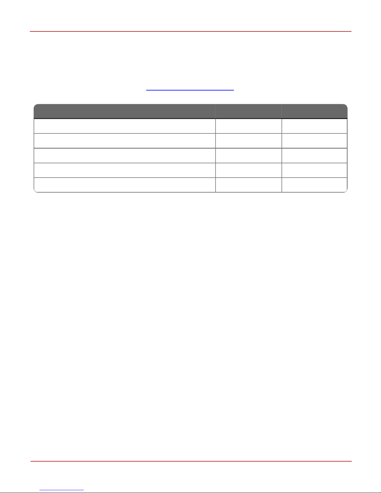
Ch1 Item# Ch2 Item#
Input Pulse Value 098 912
Input Pulse Scaling 114 913
Accumulated Volume 002 910
Incremental Accumulated Volume 226 911
Accumulated Volume Units 092 458
Accumulated Volume # of Digits 097 097
Table 1-1: Quick Reference: Items associated with Accumulated Volumes
1 Introduction
1 Introduction
The basic CNI4 assembly includes a LTE supported Cloud Link 4G Modem and a dual-channel pulse data
logger. It is designed to support most:
Commercial & industrial (C&I) applications,
Smart/automatic meter reading (AMR) analog applications, as well as
2G/3G modem-based applications.
The Cloud Link 4G Modem provides cellular communication that wirelessly transfers data originating
from the pulse data logger. The CNI4 device is battery-operated (or can be externally powered) and is
easy to configure using MasterLink R510+ configuration software over serial, bluetooth and cellular
interface.
The accumulated data from the pulse data logger can be periodically reported to Honeywell PowerSpring
R110+ Meter Data Management (MDM ) system and other third party MDMs. (The CNI4 device must be
configured as a Pulse Accumulator device in Honeywell PowerSpring.)
Two independent pulse sources may be connected to the input channels, each having its own 3.5 vdc
wetting voltage. As the two channels act as independent accumulators, typical installations might
include:
a. One pulse source (pulse transmitter or meter pulse) connected to either Ch1 or Ch2.
b. Two separate pulse sources (pulse transmitters or meter pulses): Ch1 for the first source and Ch2
for the second source.
c. Pulse outputs from one volume corrector connected to both channels, Ch1 for corrected volume
pulses and Ch2 for uncorrected volume pulses.
The pulses received at either inputs are assigned a fixed volume through their respective 'Input Pulse
Value' selections (item numbers 098 and 912 - refer to Volume related Item Numbers in the Appendix
section).
If required, additional pulse scaling (Item numbers 114 and 913 - refer to Volume related Item Numbers in
the Appendix section) can be applied to individual channels before the pulses are stored to their
respective accumulated totals.
Honeywell | 1
Page 6
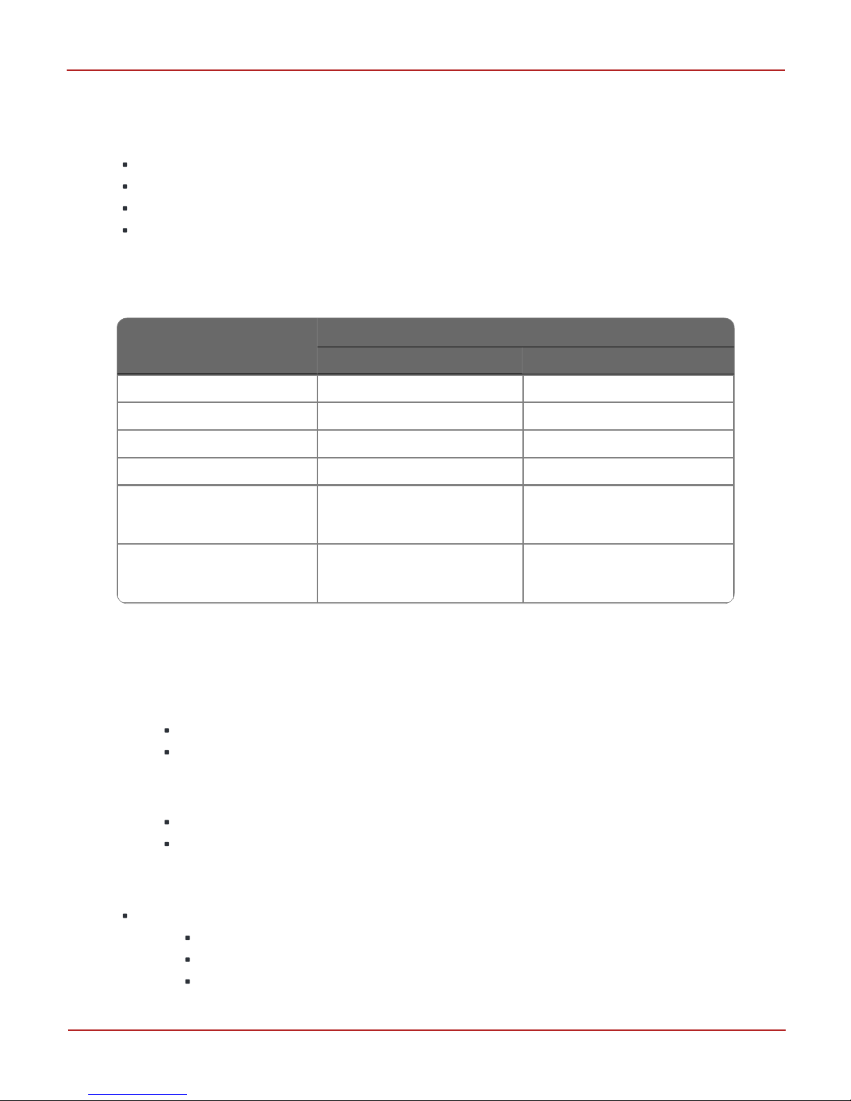
Ch1 Item# Ch2 Item#
FixedFactor Volume 000 908
Incremental FixedFactor Volume 225 909
FixedFactor Value 044 440
FixedFactor Volume Units 090 457
FixedFactor Volume Digits 096 096
Table 1-2: Quick Reference: Items associated with FixedFactor Volume
1 Introduction
Additionally, each pulse channel may also be configured to receive a user-specified FixedFactor
multiplier. By default, this multiplier is disabled but may be activated by inserting the desired factor into
item 044 for Ch1 and item 440 for Ch2. The FixedFactor feature is normally used to adjust the
accumulated uncorrected volume for a fixed pressure factor or fixed temperature factor (or both).
The number of digits for Accumulated Volume and FixedFactor Volume can also be assigned for both
channels. (item numbers 097, refer to Scaling related Item Numbers in the Appendix section.)
Honeywell | 2
Page 7
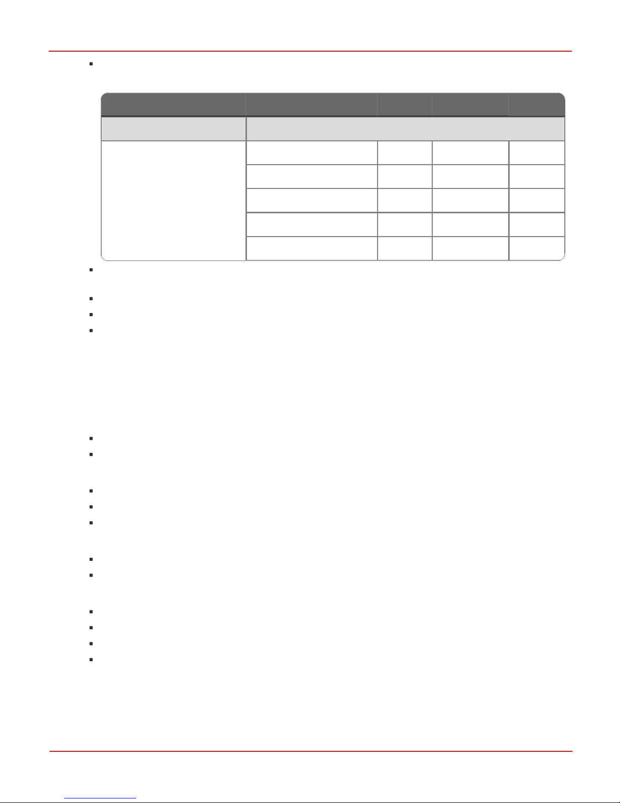
Specifications
Pulse input type
Reed Switch (mechanical) Electronic Correctors
Firmware Filter ON OFF
Min “On” Pulse Width 150 ms 40 ms
Min “Off” Pulse Width 150 ms 60 ms
Max Bounce Time 10 ms 2 ms
Max Frequency N.A.
10 Hz, 40% duty cycle
5 Hz, > 20% duty cycle
Max Reed Switch Pulse
Rate In
20 PPM, 5% duty cycle
600 PPM, 40% duty cycle
300 PPM, 20% duty cycle
Table 2-1: Pulse Input Source Specifications
2 Specifications
2 Specifications
Pulse Input Circuit
Full temperature range: -25 °C to +65 °C
Max wetting current provided = 35 micro-amps
Max Pulser + Line Resistance = 200 ohms
Max line length = 300 feet
If you are using Electronic Correctors or Reed Switch (mechanical) as a pulse input source,
follow the specifications mentioned in the table below.
Memory
41 Days (If 4 user-specified audit-trail log items are configured for hourly logging)
Power Supply
Battery
2 D-cell Lithium disposable battery pack for the Pulse Accumulator
2 D-cell Lithium disposable battery pack with super-capacitor for the Cloud Link
4G Modem
External Power Supply
Pulse Accumulator (5 to 16 V)
Communications
While using external power, the Pulse Accumulator can use a 2 D-cell Lithium
disposable battery pack as a backup.
Wireless specifications:
LTE: Five band, 700 (Bd13)/700 (Bd17)/850 (Bd5)/ AWS (Bd4)/1900MHz (Bd2)
UMTS/HSPA+: Triple band, 850 (BdV)/AWS (BdIV)/1900MHz (BdII)
GSM/GPRS/EDGE: Quad band, 850/900/1800/1900MHz
Honeywell | 3
Page 8
Parameter Conditions Min. Typical Unit
LTE Connectivity Band 2, 4, 5, 13 and 17
Receiver Input Sensitivity@
ARP (ch.bandwidth 5 MHz)
LTE 700 Band 17 -97 -102 dBm
LTE 700 Band 13 -98 -103 dBm
LTE 850 Band 5 -98 -104 dBm
LTE AWS Band 4 -100 -103 dBm
LTE 1900 Band 2 -98 -103 dBm
Table 2-2: Modem Receiver Sensitivity
2 Specifications
Bluetooth Low Enenrgy: v.4.0 (2402-2480MHz)
Certified with Verizon and also operates with other major carriers in North America such as
AT&T and Rogers.
Falls back to UMTS/HSPA and GSM/GPRS
Supports IPV4 communication
Bluetooth Low Energy interface can be used for wireless configuration
Security
SSL/TLS 1.2
(Transport Layer Security (TLS) and its predecessor, Secure Sockets Layer (SSL), both frequently referred
to as "SSL", are cryptographic protocols that provide communications security over a computer network.)
Software
Configuration: MasterLink R510+ (Windows, iOS, Android)
Data Collection: TDS /PowerSpring R110, Itron MV90 V3.0+
Enclosure
20% glass-filled polycarbonate
Weight: 3.7 lbs
Wall-mount, meter-mount and pipe-mount
Environmental
-13 °F to +149 °F (-25 °C to +65 °C)
Relative Humidity: 0 to 95% non-condensing
Certifications
Class 1, Division 2, Group D
PTCRB
Verizon
FCC
Honeywell | 4
Page 9

3 Safety
3 Safety
3.1 Limited Warranty
Honeywell Mercury Instruments, Inc. warrants all instruments covered by this manual to be free from
defects in material and workmanship under normal use and service of this product. If returned to our
factory, transportation charges prepaid, within 4 years of the original purchase shipment date, Honeywell
Mercury Instruments agrees to repair or replace any instrument which its examination reveals to have
been defective due to faulty workmanship or material. All obligations or liabilities on Mercury
Instruments part is to repair or replace warranty instruments, and does not include any other type of
claims or damages, including but not limited to consequential damages following the use or misuse of
instruments sold by it.
Honeywell Mercury Instruments reserves the right to, at any time make changes, modification or
enhancements to this product without prior notification. This warranty is in lieu of all other warranties,
express or implied. No agent is authorized to assume for Mercury Instruments any liability except as set
forth above.
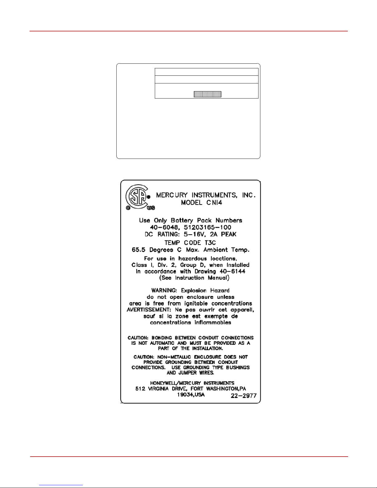
3.2 Safety in Hazardous Locations
The Mercury Instruments CNI4 is certified by CSA (CUS) for Class I, Div-2, Group D hazardous locations
when installed in accordance with CSA (CUS) control drawing 40-6144 in this manual. Operate the CNI4
device only if the instrument is completely intact. Also, ensure to comply with the applicable laws and
regulations, and company policies for the usage of the CNI4 device.
Caution: Use only Mercury Instruments manufactured battery packs with part numbers specified on
the certification label or control drawing. Use of third-party battery packs voids product warranty,
voids hazardous locations Class 1 Div 2 certifications and may impair safety.
Do not connect 51203165-100 battery pack and external power simultaneously to Cloud Link 4G Modem.
Also, do not replace the battery pack in a hazardous location.
Warning: Electrostatic discharge (ESD) can damage CMOS integrated circuits and modules. Observe
precautions for handling electrostatic sensitive devices.
Related Item: InstallationDrawing
Honeywell | 5
Page 10

3 Safety
3.3 Security
Using MasterLink R510.1, the CNI4 device can be configured through the following interfaces:
Serial (using MasterLink desktop application)
Bluetooth (using MasterLink mobile application)
Cellular (using MasterLink desktop)
To start using MasterLink Application, Administrator must be registered using the license key provided by
Honeywell. MasterLink administrator can create roles with access permissions and assign roles to
different users. With this role based access mechanism, a user is restricted to the operations that are
associated with assigned role.
A valid user name and password are required to access the MasterLink application, and a valid user ID
and access code are required to sign-in to the Cloud Link 4G Modem.
For bluetooth communication with the CNI4, the Cloud Link 4G Modem uses Just Works pairing method.
In order to connect a Cloud Link 4G Modem with MasterLink mobile app, you need to perform a bluetooth
pairing first. That said, from the security standpoint, it is advised to disable the bluetooth interface and
use the serial interface for configuration, to avoid malicious user configuration changes.
Every Cloud Link 4G Modem device has a unique IMEI and RUID numbers. RUIDs are used to identify a
device using MasterLink desktop application.
The CNI4 supports white-listing of cellular communications. You can configure up to 10 host IP
addresses for the device to allow specific hosts in case of host initiated call outs.
For communication over a cellular interface, the Cloud Link 4G Modem can use SSL/TLS 1.2 certificates
for mutual authentication and secure connection. The following certificates can be loaded for secure
communication over a cellular interface.
Client Certificate - A client certificate is a type of digital certificate that is used by client
systems to make authenticated requests to a remote server.
Server Certificate - Server certificates or SSL certificates are small data files that digitally bind
a cryptographic key to an organization's details.
Private Key (Encrypted) - The private key is used to decrypt the information and restore it to its
original format so that it can be read.
CA Certificate - A Certification Authority (CA) is a trusted entity that issues electronic
documents that verify a digital entity's identity on the Internet.
All files transferred to an Android device for use by MasterLink Software must be deleted after use to
ensure that there is no data loss / leak. It is recommended to keep the Android phone or iPhone used for
MasterLink Software updated with the security patches released by the respective platforms.
It is also recommended to enable SSL for secure communication with MasterLink Software R510.1.
Honeywell | 6
Page 11
CNI4NAME
MODEL NO.
S/N
XXXXXXXX
YYYY/MM
MERCURY
INSTRUMENTS
Country of origin:
Mexico
HOneywell
This device complies with
Part 15 of the FCC Rules.
Operation is subject to the following two
conditions: (1) This device may
not cause harmful interference, and
(2) This device must accept any
interference received,including interference
that may cause undesired operation.
3 Safety
3.4 Label
Check the material label and serial number label.
Figure 3-1: Label - Serial Number
Figure 3-2: Material label
Honeywell | 7
Page 12
4 Mechanical Assemblies
4 Mechanical Assemblies
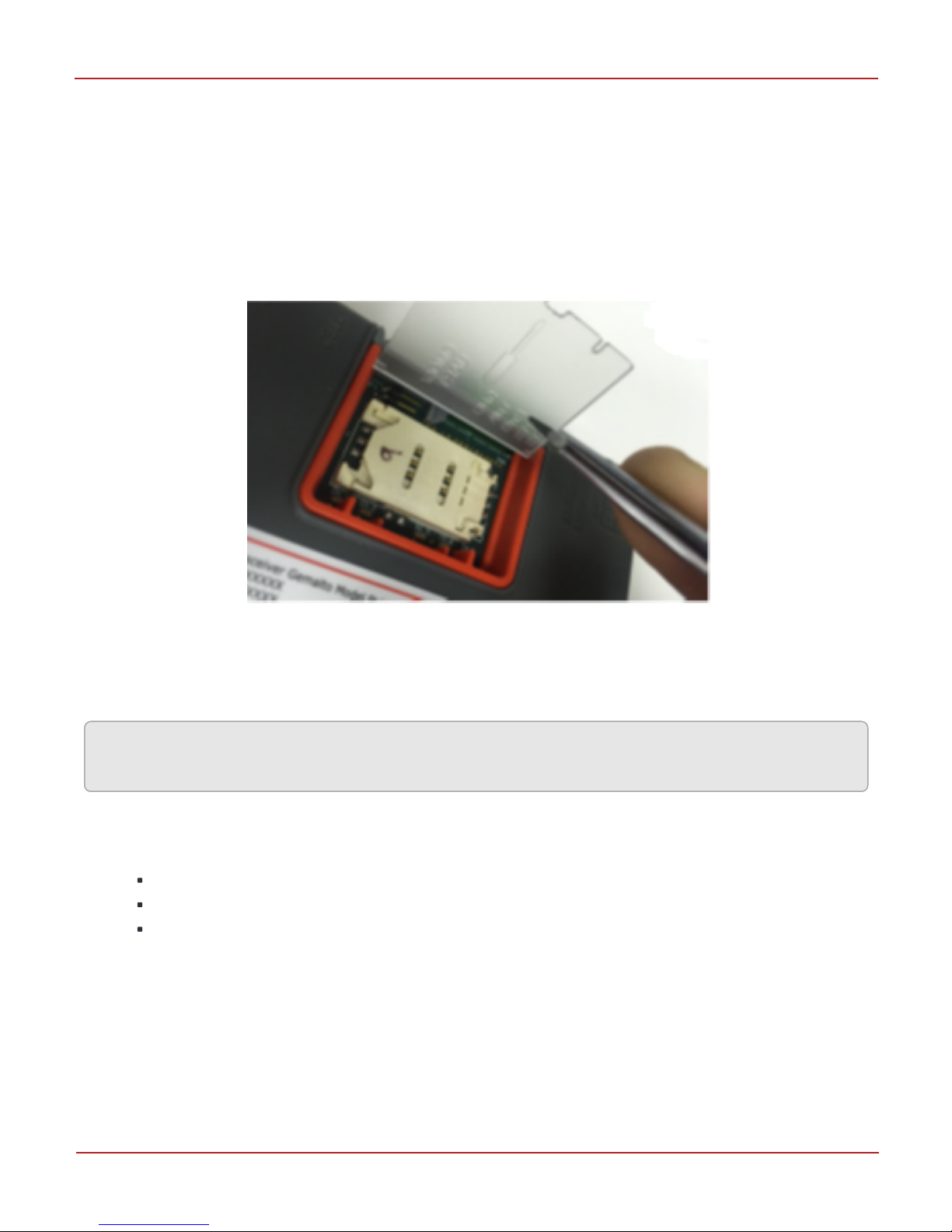
4.1 Installing the SIM Card
The Cloud Link 4G Modem has a connector that holds the cellular radio Standard SIM card. Cloud Link
4G Modem supports both 1.8V (Class C) and 3.0V (Class B) version SIM cards.
To install the SIM card:
1. Lift the cover on the Cloud Link 4G modem.
2. Slide the white SIM card holder to the right, then lift the left edge.
3. Insert a SIM card into the slot provided and close the card holder.
4. Slide the SIM card holder to the left until it snap locks.
5. Close the cover.
Attention: To avoid damage to the SIM card, ensure that the CNI4 / Cloud Link 4G Modem is powered
down before inserting or removing the SIM card.
damage may result to the SIM card.
4.2 Instrument Mounting Options
The instrument mounting options must be clearly specified at the time of order to ensure that everything
a field technician needs is available at the time of installation. A CNI4 device can be mounted using one
of the following options:
Wall mount
Meter mount
Pipe mount
Honeywell | 8
Page 13
4 Mechanical Assemblies
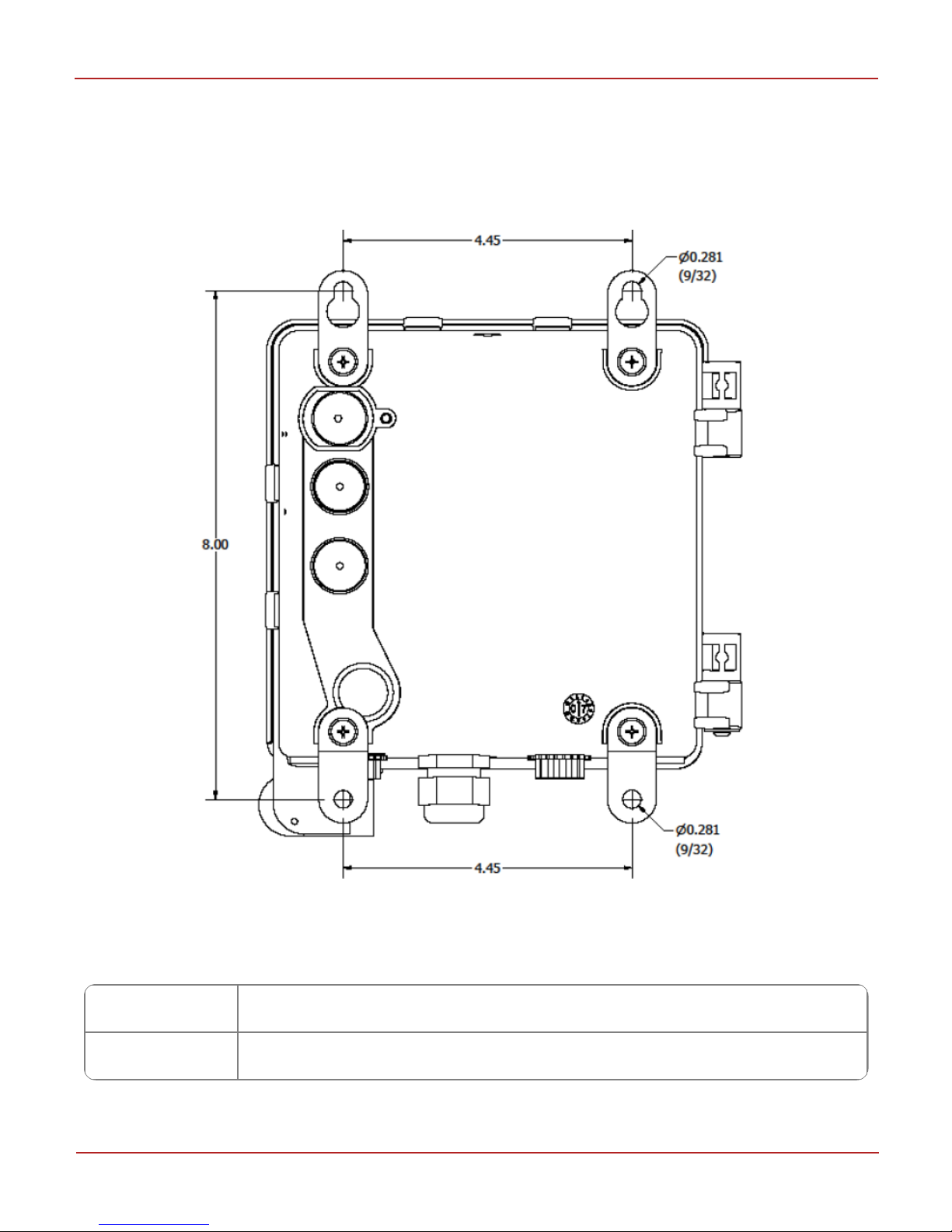
4.2.1 Wall Mounting
Where a flat wall surface is available, such as on the side of a building or shed, stainless steel “hangers”
can be utilized. Illustrated below is the rear view of a CNI4 with associated mounting dimensions (in
inches).
Figure 4-1: Wall Mounting Tabs and Dimensions
Recommended wall and fasteners
Recommended
Wall
Fasteners Stainless Steel Thread Forming ¼" dia-1.25"length, Screw size 0.25" Min Torque 56
Brick Wall
lb.in.
Honeywell | 9
Page 14
4 Mechanical Assemblies
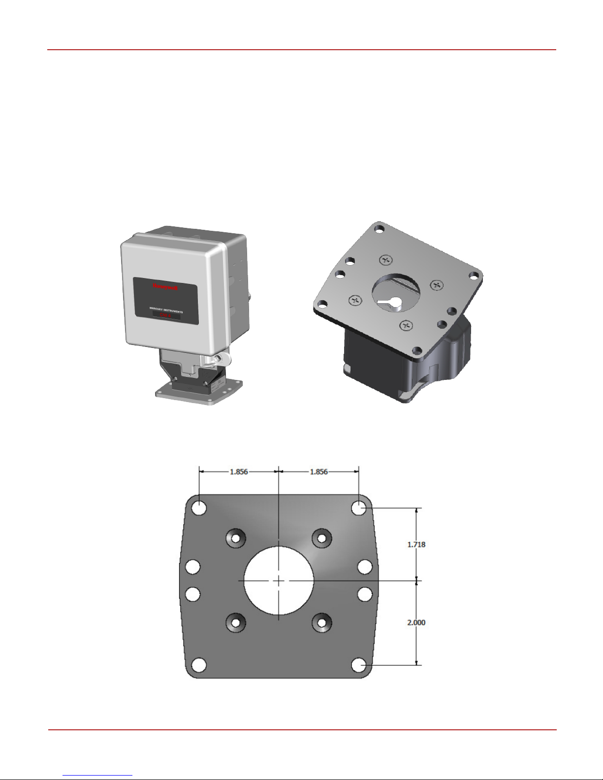
4.2.2 Meter Mounting
The UMB (Universal Mounting Bracket) option is used when the index base has to be mounted directly to
a meter. The advantage this option provides is that you can mount the entire instrument without being
concerned about routing external meter pulse signal wires. You can mount the UMB index base on rotary,
turbine, and diaphragm gas meters that have a rotating instrument drive output. This includes American,
Rockwell, Romet, Roots, or Schlumberger meters.
The UMB housing may be rotated about the base plate so that the instrument and index will face in any
of four directions. To mount, remove all four screws (provided with the kit) which attach the base plate to
the bracket housing. Replace and tighten the four screws after repositioning the UMB housing.
Figure 4-2: CNI4 with Universal Mounting Bracket (UMB)
Reference dimensions for the base plate are shown here. All dimensions are in inches.
Figure 4-3: Universal Mounting Bracket (UMB) Hole Pattern
Honeywell | 10
Page 15
4 Mechanical Assemblies
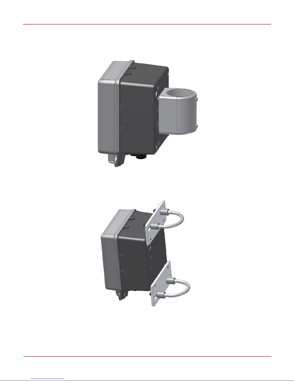
4.2.3 Vertical Pipe Mounting
Another mounting option available for the CNI4 is the pipe-mount. In this option, the adaptor will accept
a 2 inch diameter galvanized pipe, and is secured in place with a pair of Allen-Head Set Screws.
Figure 4-4: Pipe Mounting using Collar
Shown below is a U-Bolt mounting option. This is optimized for metal pipe with an outside diameter of
2”.
Figure 4-5: Pipe Mounting using U-Bolts
Honeywell | 11
Page 16
Hole to lock and
seal the device
4 Mechanical Assemblies
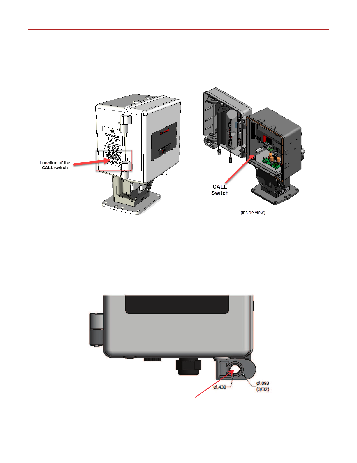
4.3 Call switch
In the CNI4 device, a CALLswitch (magnetic reed switch) is located inside the left side of the instrument
enclosure, behind the material label. This allows the field technician to initiate a call without the need to
open the door of the unit. A hand-held magnetic wand is simply placed against the outside of the
enclosure for a few seconds.
Figure 4-6: CALL switch
4.4 Enclosure Sealing
You need to open and close the device door to configure the CNi4 device. After configuring the CNI4
instrument, close the device lid and lock the door.
Seal the enclosure either using a conventional lock through the larger hole or by a security wire seal
through the smaller hole.
Figure 4-7: Enclosure Sealing Options
Honeywell | 12
Page 17
4 Mechanical Assemblies
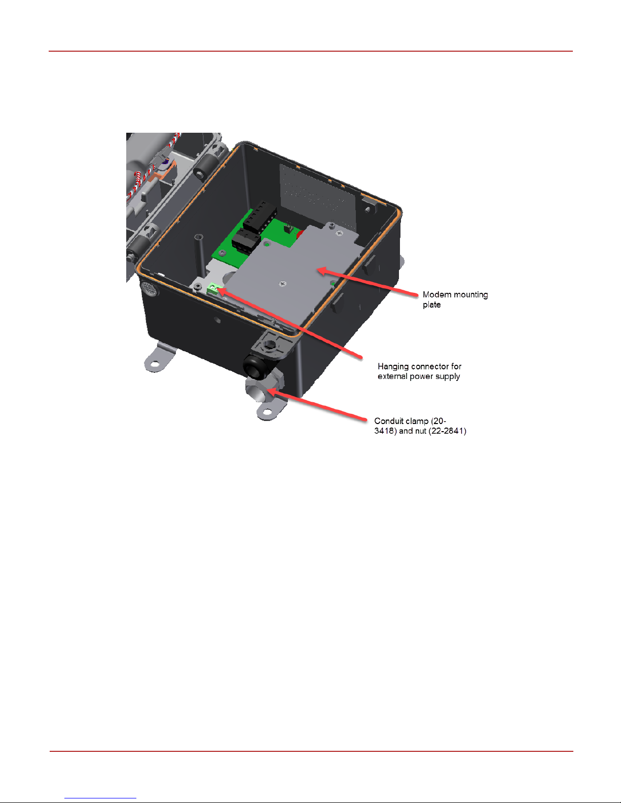
4.5 CNI4 device without the modem
If you have ordered a CNI4 device without the Cloud Link 4G modem, the device will be shipped with a
modem mounting plate installed (see figure below). This enables you to order a Cloud Link 4G modem at
a later time, and retrofit it inside the CNI4 device.
Antenna and terminal block position (external dc power) are same for both meter and wall mount
For Div 2 installation with external power option: The enclosure is supplied with a rigid metal conduit
clamp 20-3418 and nut 22-2841
Honeywell | 13
Page 18
5 Electrical Assemblies
5 Electrical Assemblies
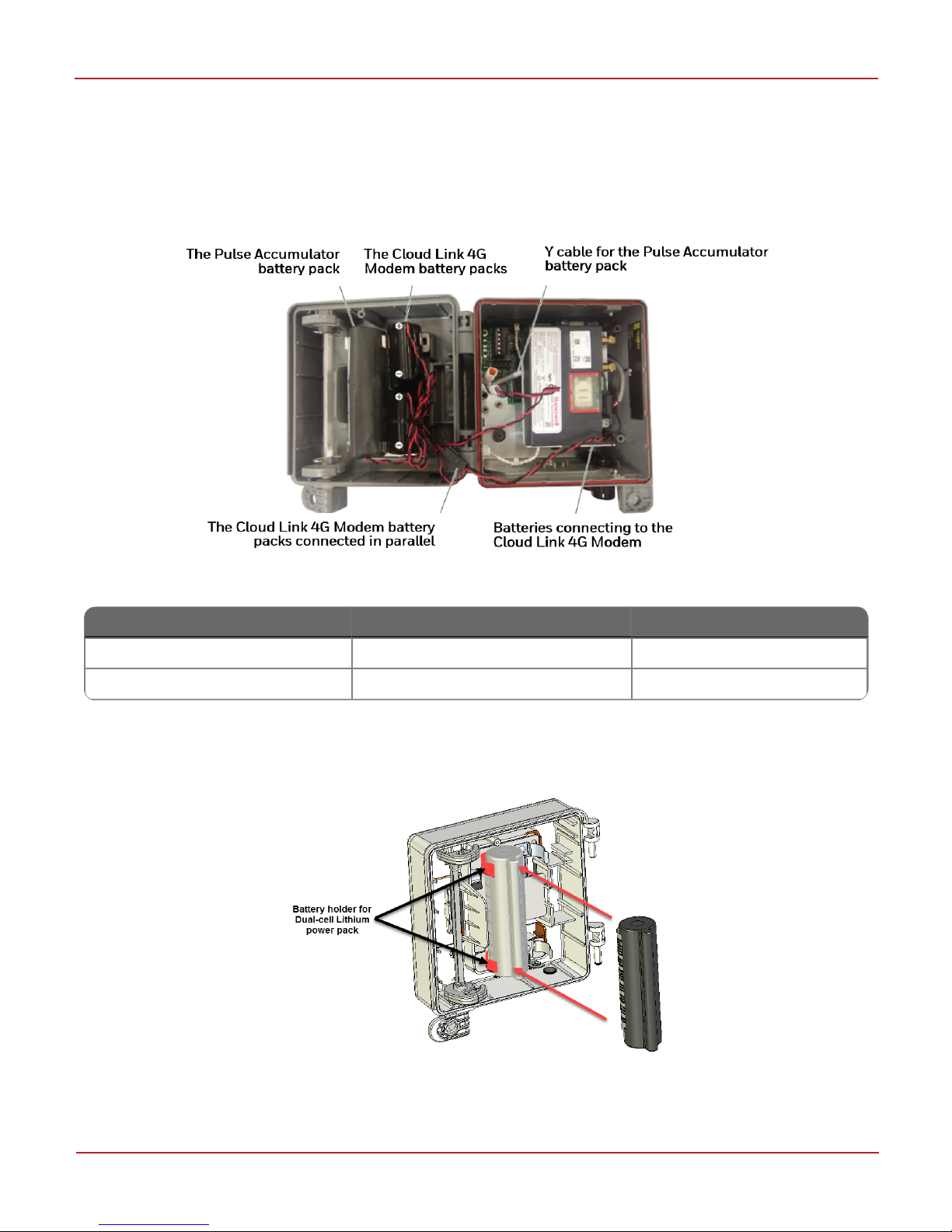
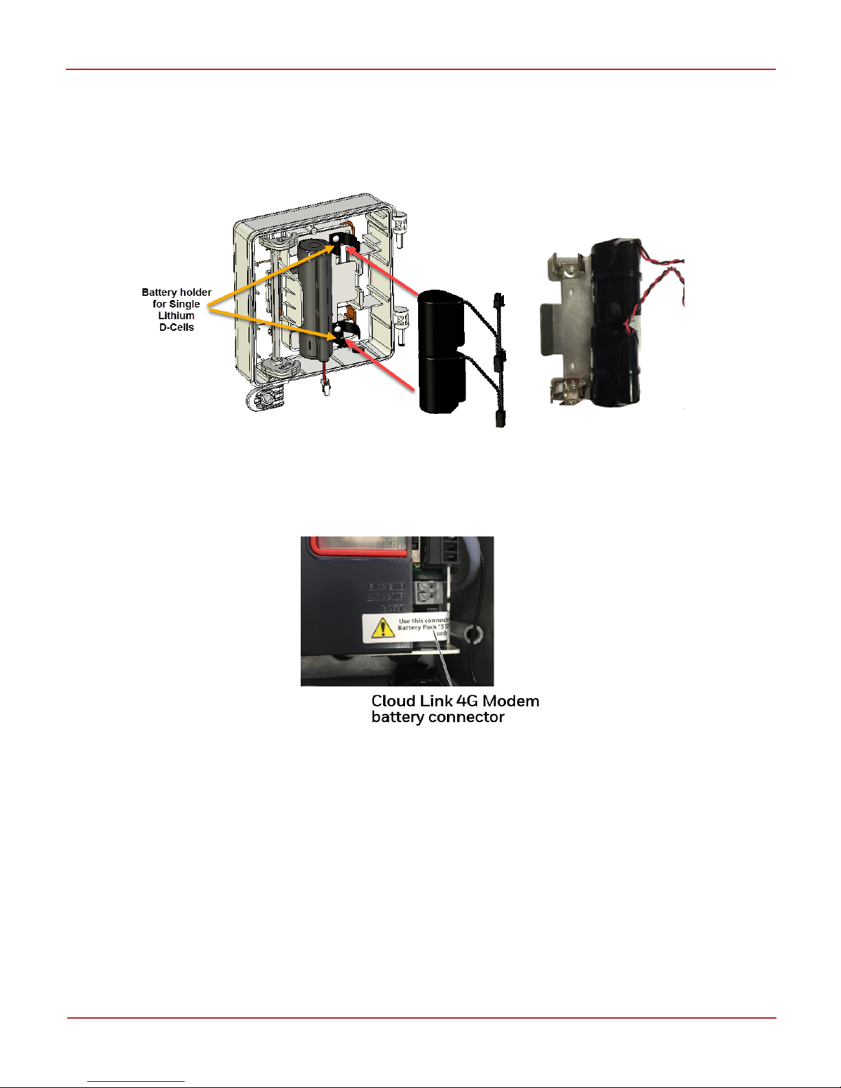
5.1 Internal Battery Power Options
Shown below is the CNI4 device with the Pulse Accumulator and Cloud Link 4G Modem battery packs
installed and wired.
Figure 5-1: Lithium Battery Pack Mounting
Component Battery pack Ordering Part Number
Pulse Accumulator Dual-cell Lithium power pack 40-6048
Cloud Link 4G Modem Single Lithium D-Cell 51203165-100
To connect the battery pack to the Pulse Accumulator
1. Insert the Pulse Accumulator battery pack into the battery holder provided on the enclosure door.
2. Connect the Pulse Accumulator battery pack to the Y cable.
3. Wrap the extra wire using a cable tie.
Honeywell | 14
Page 19
5 Electrical Assemblies
To connect the battery packs to the Cloud Link 4G Modem
1. Insert the Cloud Link 4G Modem battery pack into the battery holder provided on the enclosure
door. You can also connect two battery packs in parallel, and install them in place as shown in the
figure below.
2. Tie-wrap the batteries to the metal plate.
3. Connect the female connector from the first battery to the male connector of the second battery.
4. Remove the warning label as shown in the picture, and then remove the dummy battery connector
plug on the Cloud Link.
5. Attach the connector from the second battery to the Cloud Link battery connector.
6. Wrap the extra wire using a cable tie.
5.1.1 Battery Replacement
Batteries must be replaced in non-hazardous location or after ensuring the area is free from hazardous
gases. Before replacing the Pulse Accumulator battery connect the fresh battery to the free-end of the Ycable to avoid power interruption.
Replacement of internal battery packs is quick and convenient by pressing left-wards on the large plastic
tab and pulling the pack out. Take care to not lose grip of the battery pack while disconnecting the power
connector from the Pulse Accumulator board.
Honeywell | 15
Page 20

5 Electrical Assemblies
5.1.2 Extending Battery Life
The CNI4 is designed to provide a long service life when operating from batteries. Total battery life is
influenced by two factors in the CNI4 — continuous background current and high current draw during
cellular calls. The background current can be minimized to a certain extent by using fewer pulse input
connections and using normally-open (Form-A) contacts for pulse and alarm sensing. High current draw
depends on the number and duration of cellular calls made. This can be minimized by ensuring the CNI4
has strong cellular reception (which minimizes call retries) and by limiting the number of regular
scheduled calls to a practical extent.
The battery life also depends on bluetooth advertisement interval and so it is recommended to optimize
the usage of bluetooth.
5.2 External Power Option
A 3 Pin connector is available on the Y-cable to connect to an external power supply. Where AC power is
readily available, as is the case at some sites, use a power adaptor to supply the necessary voltage. The
power adaptor is required to be capable of sourcing Class 2 power supply with 2A rated current, 5V to 16V
range.
To setup external power supply
1. Remove the housing of the metal conduit and route the power cable through it.
2. Connect the power cable to the 3-Pin power connector on the Pulse Accumulator Board.
3. Connect the other end of the power cable to an external power source (5 to 16 V, 2A peak current).
The output voltage from the power adaptor can be wired to the positive and GND terminals of the 3 pin
connector shown above. It may be necessary to check with a voltmeter to determine the positive and GND
wires coming from the power adaptor. Polarity of the terminal block connection will be apparent from the
wire color — Red is positive and Black is negative.
Attention: In the event of a reverse connection, no harm will be caused to the electronics but the CNI4
will not power as expected.
Honeywell | 16
Page 21
Connector to the
Pulse Accumulator
Connector to the
Cloud Link 4G Modem
USB connection
to the PC
5 Electrical Assemblies
5.3 Connecting the external pulse inputs
(Applicable for wall-mounted units only)
It is possible to connect a maximum of two external pulse inputs at TB2 (Terminal Block 2) of the Pulse
Accumulator.
A 3.5 VDC wetting voltage is provided by each Pulse Accumulator input channel. If the pulse channel is to
be wired to an active device, i.e. transistor-type output, be sure to observe polarity.
To connect the external pulse inputs
1. Remove the housing on the cable gland and route the pulse input(s) cable through it.
2. Unplug the male 4-Pin terminal block connector.
3. Connect the external input pulse wires of the cable into the appropriate slot on the 4-Pin terminal
block connector.
4. Reconnect the 4-Pin terminal block connector.
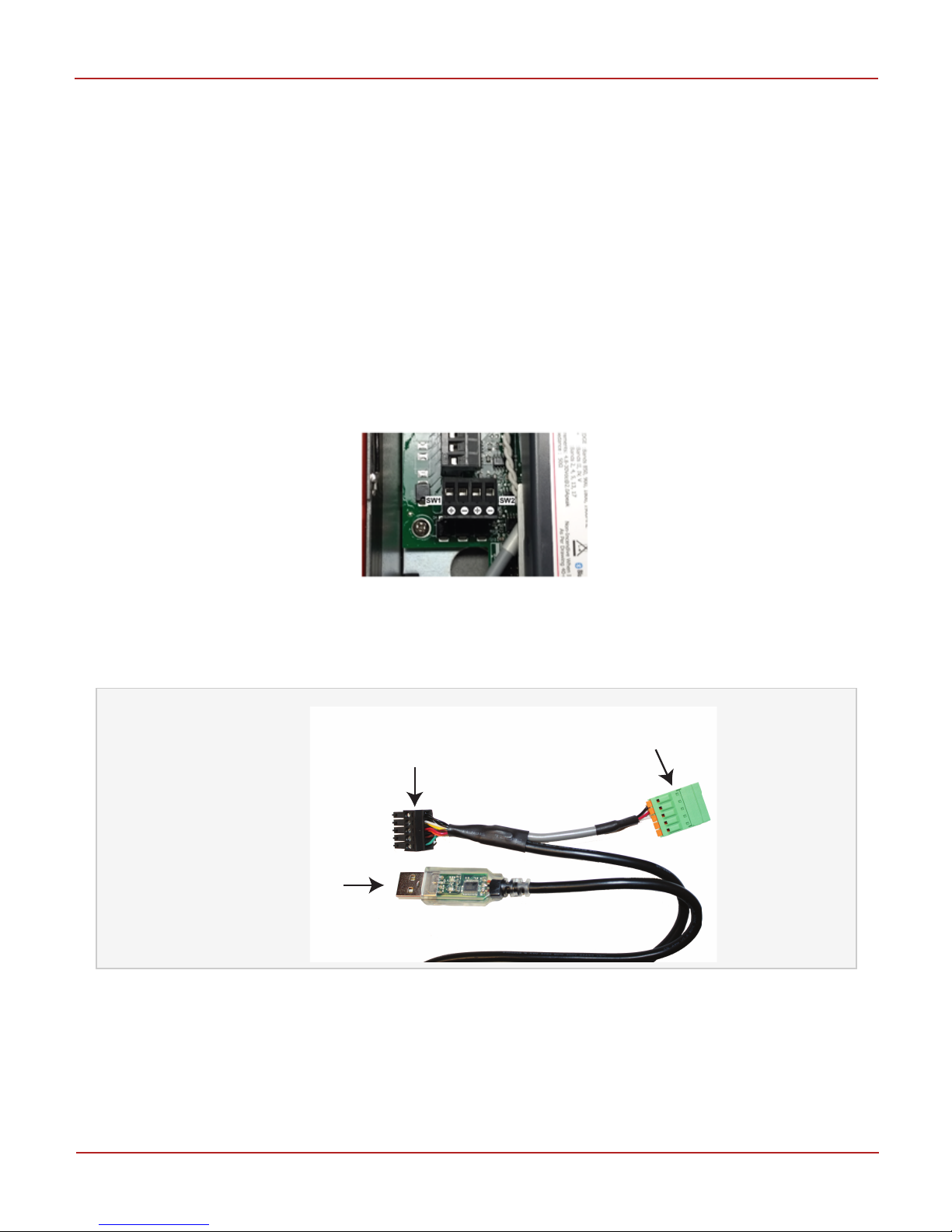
5.4 USB-to-serial cable
You can use the MasterLink Software (R510.1 or higher) to configure the Pulse Accumulator and the
Cloud Link 4G Modem as two independent sites, using the USB-to-serial cable (40-6147-kit).
Figure 5-2: The USB-to-serial cable (40-6147-kit)
One end of the cable has a USB connector and the other end includes a male and female connector. The
male (black) connector connects to the Cloud Link 4G Modem, and the female (green) connector connects
to the Pulse Accumulator.
Honeywell | 17
Page 22
5 Electrical Assemblies
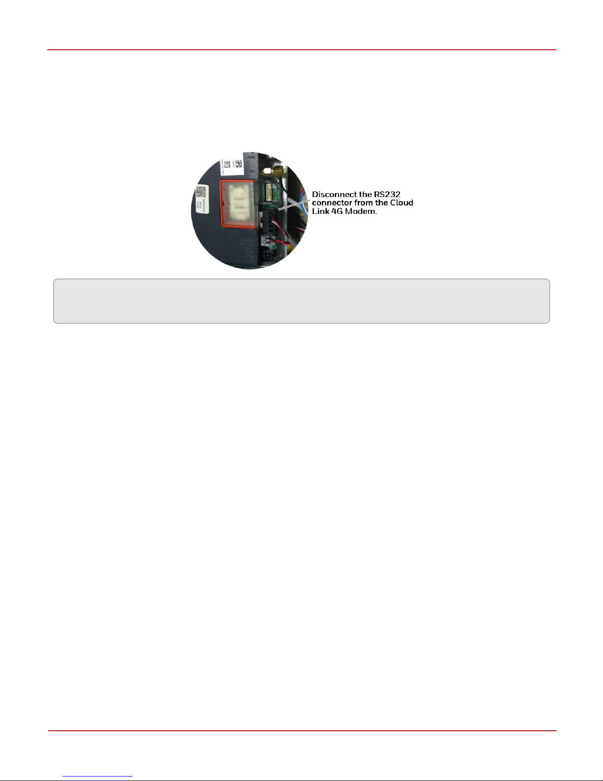
5.5 Disconnecting the serial interface cable
To configure the Cloud Link 4G Modem and the Pulse Accumulator, you need to disconnect the serial
cable interface connecting them. To do this, Disconnect the RS232 connector connected to the Cloud
Link 4G modem, and then use the USB-to-serial cable (40-6147-kit) to continue with the configuration
process.
Attention: After configuration is complete, remember to resore the original serial interface between the
Pulse Accumulator and the Cloud Link 4G Modem.
Honeywell | 18
Page 23
5 Electrical Assemblies
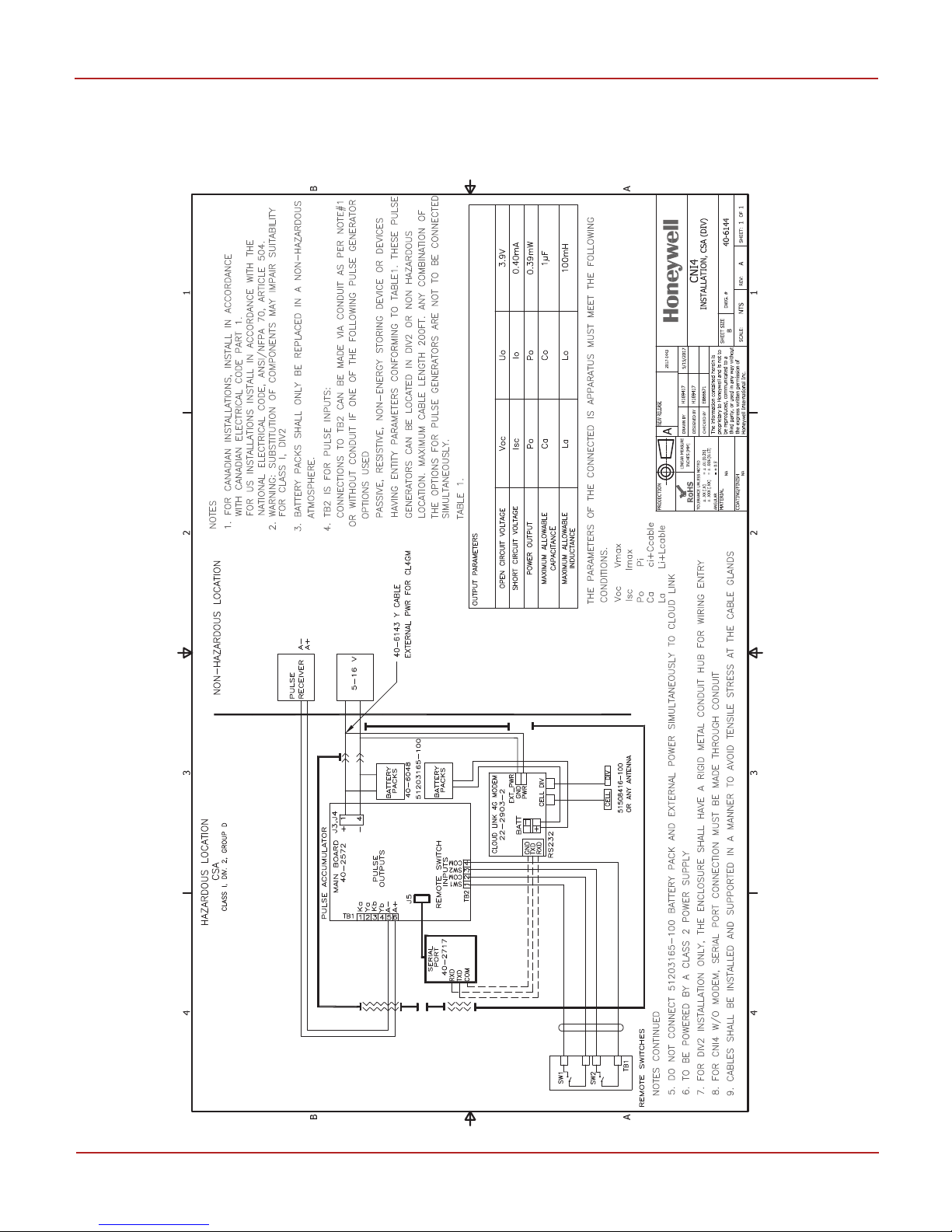
5.6 Installation Drawing
CNI4 device for Class I Division 2 must be connected to other circuits as per the below installation
drawing (40-6144). Substitution of components may impair suitability for use in a hazardous location.
Honeywell | 19
Page 24

6 Getting Started with a CNI4 device
6 Getting Started with a CNI4 device
Follow the steps below to get started with a new CNI4 device:
Step 1: Open the door of the CNI4 and install the SIM Card
Step 2: Power-up the CNI4 — via battery or external power supply
Step 3: Connect the external pulse inputs (applicable for wall-mounted option only)
Step 4: Disconnect the serial cable interfacing the Pulse Accumulator and the Cloud Link 4G Modem
Step 5: Configure the Pulse Accumulator using serial connection
Step 6: Configure the Cloud Link 4G Modem using serial connection
Step 7: Restore the original serial cable connection
Step 8: Close and lock the door
Honeywell | 20
Page 25

7 Configuration
7 Configuration
MasterLink software is used to configure the CNI4 device. MasterLink R510.1 is available as a Windows
application and also as an app that can be installed on iOS and Android devices.
CNI4 Configuration scenarios are listed here:
Using the MasterLink Windows application you can:
Configure the Pulse Accumulator and the Cloud Link 4G Modem as separate sites by connecting
to them individually using a serial cable. In this case, both must have the same Site ID.
Configure the CNI4 device as an integrated device by connecting to it over internet.
Configure the CNI4 device as a single site, and using the same site you can connect to the Pulse
Accumulator / Cloud Link 4G Modem individually through serial communication.
Using the MasterLink mobile app, you can connect to the CNI4 device over Bluetooth, and configure it as
an integrated device.
7.1 Getting started with MasterLink
On launching the MasterLink, you will see a screen to log on.
To start using MasterLink Application, Administrator must be registered using the license key provided by
Honeywell. After the site administrator is registered, they can create new users using Security feature.
For individual user, the generated license key must be emailed to them by the administrator allowing
them to register and start using MasterLink.
Honeywell | 21
Page 26

7 Configuration
For a first time user, click New User and register. Enter the log-in details, browse and select the license
key, and then click Register. The user-name you enter while registering must match with the user name
used while creating the license key.
The Login screen appears. Log in with your credentials. Click Sign In.
Honeywell | 22
Page 27

7 Configuration
The following screen is displayed.
Download a copy of the MasterLink Guide for more information on using Honeywell MasterLink.
Honeywell | 23
Page 28

7 Configuration
7.2 Configuring a Pulse Accumulator using serial connection
To configure the Pulse Accumulator using serial connection:
1. Disconnect the serial cable interface connecting the Pulse Accumulator and the Cloud Link 4G
Modem.
'
2. Insert the female connector of the Pulse Accumulator into the male connector of the USB-to-serial
cable (40-6147-kit).
3. Connect the USB end of the serial cable to a PC running the MasterLink R510.xx desktop
application.
4. Launch and login to the MasterLink R510.xx desktop application.
5.
Navigate to the Settings menu. In the 'Communications Setup' tab, select the Serial Port Connector
and the Baud Rate (default value = 9600) and Click OK.
Note: If multiple serial port connectors are detected, then ensure that you select the
correct port using the Connector drop-down. Also, ensure that you set the baud rate to
match the baud rate of the connected instrument.
Honeywell | 24
Page 29

7 Configuration
6.
Click Connect. MasterLink starts connecting to the Pulse Accumulator.
When connecting to the Pulse Accumulator for the first time, as the site is not already added
to MasterLink, you will see the following warning message asking you to add the site to
MasterLink.
This warning is not displayed, if the site is already added to MasterLink.
7. Close the warning message. The following screen appears.
8.
Edit the Site Name.
Click Save to continue.
Honeywell | 25
Page 30

7 Configuration
The instrument dashboard appears. Also, the site is added to the list of sites on the site
management screen.
Note: Before making any changes to the connected instrument, ensure that you wait till
the dashboard data is completely loaded.
9.
Click the center of the Time Sync widget and perform a time synchronization between the Pulse
Accumulator and the PC by clicking Sync. You need to perform a time sync if you see a difference in
the instrument time and the host (PC) time. Othervise you can skip this step.
10.
Navigate to View/Edit > Configure by Group > Site Information and change the Site ID to the value
required by MDM software.
11.
Navigate to View/Edit > Configure by Group > Modem Call-in Configuration.
Honeywell | 26
Page 31

Item No. Description
Recommended Value
333 Call-in Trigger 3 = Alarm & Scheduled Call-in
449 Switch Filtering 1 = Filter Both Channels
486 Modem AT-Command Enable 1-Yes
334 Scheduled Call-In Date Set to the desired Call-In Date
335 Scheduled Call-In Time Set to the desired Call-In Time
336 Call-In Retry By Instrument
339 Scheduled Call-In Phone number
<IP>/<Port>Example:
192.168.1.1/50467
485 Call-Out Stop Time 00:00:00
490 Call-Out Start Time 00:00:00
493 Alarm Call-In Phone number
<IP>/<Port> Example:
192.168.1.1/50467
495 Modem Retry Interval A 5 minutes
496 Modem Retry Interval B 1440 minutes
497 Modem Retry A Count 3
7 Configuration
Select the check-box next to an Item number, enter a value in the text box provided and then
click on Write Item button to write the value against the item in the connected
instrument/device. You can search for a specific item number and can also modify multiple
Item Numbers at once. You can also use the Read Item button (enabled only when an item is
selected) to read the currently configured value of the item numbers.
Set the following parameters:
12.
Click Disconnect to disconnect MasterLink from the Pulse Accumulator. On successful
disconnection from the Pulse Accumulator, a status message is displayed. Close the pop-up to
acknowledge the message.
Honeywell | 27
Page 32

7 Configuration
7.3 Configuring a Cloud Link 4G Modem using serial connection
To configure the Cloud Link 4G Modem using serial connection:
1. Disconnect the male connector of the USB to serial cable that was previously connected to the
Pulse Accumulator.
2. Insert the male connector, so far unused, of the USB-to-serial cable into the female RS232
connector slot on the Cloud Link.
3. Connect the USB end of the serial cable to a PC running the MasterLink R510.xx desktop
application.
4. Launch and login to the MasterLink R510.xx desktop application.
5.
Navigate to the Settings menu. In the Communications Setup tab, select the Serial Port Connector
and the Baud Rate (default value = 9600) and Click OK.
Note: If multiple serial port connectors are detected, then ensure that you select the
correct port using the Connector drop-down. Also, ensure that you set the baud rate to
match the baud rate of the connected instrument.
Honeywell | 28
Page 33

7 Configuration
6.
Click Connect. MasterLink starts connecting to the Cloud Link 4G Modem.
When connecting to the Cloud Link 4G Modem for the first time, as the site is not already
added to MasterLink, the following warning message appears asking you to add the site to
MasterLink.
This warning is not displayed, if the site is already added to MasterLink.
7. Close the warning message. The following screen appears.
8.
Edit the Site Name.
Click Save to continue.
Honeywell | 29
Page 34

Item
No.
Description Verizon Non-Verizon
3071 Verizon enable 1 = Enable 0 = Disable
3016 Fetch Radio Parameters 1 = Set 1 = Set
3021 ModemIPType 0 = IPv4 0 = IPv4
3022 Packet Service Connection ATD*99***3# ATD*99#
7 Configuration
The instrument dashboard appears. The site is added to the list of sites on the Site
Management screen.
Note: Before making any changes to the connected instrument, ensure that you wait till
the dashboard data is completely loaded.
9.
Wait for the dashboard to load. Click the center of the Time Sync widget and perform a time
synchronization between the Cloud Link 4G modem and the PC by clicking Sync. You need to
perform a time sync if you see a difference in the instrument time and the host (PC) time. Othervise
you can skip this step.
10.
Navigate to View/Edit > Configure by Group > Radio Configuration.
Select the check-box next to an Item number, enter a value in the text box provided and then click
on Write Item button to write the value against the item in the connected instrument/device. You
can search for a specific item number and can also modify multiple Item Numbers at once. You can
also use the Read Item button (enabled only when an item is selected) to read the currently
configured value of the item numbers.
Set the following parameters:
Honeywell | 30
Page 35

Item
No.
Description Verizon Non-Verizon
Command
3064 Manual APN Enable 1 = Enable 1 = Enable
3023 APN Name Provided By Verizon Example for AT&T:
12221.mcs
Item No. Description Recommended Value
3142 MiWireless Enable 1 = Enable
3028 Cellular session timeout 180 seconds
7 Configuration
Note: To make an internet connection, The Cloud Link 4G modem requires an Internet APN
(access point name) from the cellular service provider. In order to connect to the Internet, the
provider has its own computer equipment called a “gateway” server. The server will usually have
an APN in the form of a domain name, such as “myserviceprovider.com” or a generic name such
as “proxy”. Contact your service provider for this information.
11.
To enable MiWireless mode, Cloud Link must be externally powered and modem session timeout
must be configured to 180 seconds.
Attention: Restart the Cloud Link 4G modem after changing the 'Cellular session timeout'.
12. Disconnect MasterLink.
13.
Power cycle the Cloud Link 4G Modem.
Honeywell | 31
Page 36

If.. Then..
You know the Site ID of Pulse Accumulator
and RUID of Cloud Link 4G modem
Continue with the procedure mentioned below, and
configure the CNI4 device as an integrated site in
MasterLink.
You do not know the Site ID or RUID Connect to Cloud Link 4G Modem, and Pulse
Accumulator individually over serial, and then make a
note of the Site ID and the RUID before configuring the
CNI4 device as an integrated site.
7 Configuration
7.4 Configuring an integrated CNI4 device using serial connection
Before configuring an integrated CNI4 site in MasterLink, ensure that you are aware of the Site ID of
Pulse Accumulator and RUID of Cloud Link 4G modem, and they must be the same.
Warning: If you have configured the Pulse Accumulator and the Cloud Link 4G Modem as separate
standalone sites in MasterLink, ensure that you delete those sites before adding a new CNI4 site as
an integrated device.
To configure a CNI4 device using serial connection:
1. Ensure that the USB-to-serial cable is connected to one of the components (Cloud Link 4G Modem
OR Pulse Accumulator) inside the CNI4 device and a computer running MasterLink software.
Attention: Do not connect and use both the black and green connectors at the same time. Only
one connector (either black OR green) can be used at any given point of time. If you are using
the black connector to connect to the Cloud Link 4G Modem, ensure that the female (green)
connector is disconnected. If you are using the green connector to connect to the Pulse
Accumulator, ensure that the male (black) connector is disconnected.
2. Launch and login to the MasterLink R510.xx desktop application.
Honeywell | 32
Page 37

7 Configuration
3.
Select the Site menu, and on the 'Site Management' screen, click Add Site.
The following screen appears.
4. Configure the following site properties:
Site Name: The name of the connected site.
Site Location: The location where the instrument is installed.
Site ID: The first eight digits of the user assigned, site identification number. The
entry is limited to only characters: 0-9, therefore characters “.” and “-” are not valid.
Site ID 2: The second set of eight digit, site identification numbers.
Honeywell | 33
Page 38

7 Configuration
Click Save to continue.
The site is added to the list of sites on the Site Management screen.
User ID: User ID used to log-in to the device. Valid User IDs are 0 through 99
(decimal numeric).
Instrument Access code: Passcode used to log-in to the device. Valid passcodes are
00000 through 99999 (decimal numeric). The Passcode must be 5 digits in length.
Internet/Phone: None. Not applicable as the device is being configured to connect
over serial.
Other fields displayed on the screen can be left blank.
5.
Navigate to the Settings menu. In the 'Communications Setup' tab, select the Serial Port Connector
and the Baud Rate (default value = 9600) and Click OK.
Note: Note: If multiple serial port connectors are detected, then ensure that you select the
correct port using the Connector drop-down. Also, ensure that you set the baud rate to match
the baud rate of the connected instrument.
Honeywell | 34
Page 39

7 Configuration
6.
Access the Site menu, and from the Site Management screen, click and select the newly added CNI4
site, and then click on the Serial link.
MasterLink starts connecting to the CNI4 device over serial interface.
Honeywell | 35
Page 40

7 Configuration
While using the
USB-to-serial cable
IF.. MasterLink recognizes
the connected CNI4
device as..
The USB end of the
Male (black) connector is connected to
Cloud Link 4G Modem
Cloud Link 4G Modem
connector is
connected to a
OR
computer running
MasterLink
Female (green) connector is connected
Pulse Accumulator
to the Pulse Accumulator
The instrument dashboard appears.
If the Female (green) connector is connected to the Pulse Accumulator, MasterLink
recognizes the connected CNI4 device as Pulse Accumulator.
If the Male (black) connector is connected to Cloud Link 4G Modem, MasterLink recognizes
the connected CNI4 device as Cloud Link 4G Modem.
Honeywell | 36
Page 41

7 Configuration
Note: Before making any changes to the connected instrument, ensure that you wait till
the dashboard data is completely loaded.
7.
In the View/Edit menu, use the 'Configure by Group' tab to modify the Item Numbers. Select the
check-box next to an Item number, enter a value in the text box provided and then click on Write
Item button to write the value against the item in the connected instrument/device. You can also
use the Read Item button (enabled only when an item is selected) to read the currently configured
value of the item numbers.
Honeywell | 37
Page 42

7 Configuration
7.5 Connecting to an integrated CNI4 device over internet
Attention: Before connecting to an integrated CNI4 device over internet, ensure that the Cloud Link 4G
Modem is in MiWireless mode and is externally powered. Also ensure that the modem is connected to
the cellular network and the modem is assigned a static IP.
To configure and connect to a CNI4 device over the internet:
1.
On the Site Management screen, click Add Site.
The following screen appears.
Honeywell | 38
Page 43

7 Configuration
2. Configure the CNI4's site properties.
Site Name: The name of the connected site.
Site Location: The location where the instrument is installed.
Site ID: The first eight digits of the user assigned, site identification number. The
entry is limited to only characters: 0-9, therefore characters “.” and “-” are not valid.
Site ID 2: The second set of eight digit, site identification numbers.
User ID: User ID used to log-in to the device. Valid User IDs are 0 through 99
(decimal numeric).
Instrument Access code: Passcode used to log-in to the device. Valid passcodes are
00000 through 99999 (decimal numeric). The Passcode must be 5 digits in length.
Internet/Phone: Internet IPv4 (because the device is being configured to connect
over the internet).
Site Phone/IP address: The static IP and port number used to connect to the device.
[Use the port number configured for Cloud Link 'Server mode IP port number' =
3111, refer Modem Item Numbers under Appendex section.]
Other fields displayed on the screen can be left blank.
Click Save to continue. The site is added to the list of sites on the Site Management screen.
Honeywell | 39
Page 44

7 Configuration
3. Select the CNI4 site. The following screen appears.
4.
Click on Internet.
MasterLink starts connecting to the CNI4 device over the air using TCP/IP.
Honeywell | 40
Page 45

7 Configuration
After the CNI4 device is connected, the device dashboard appears.:
Note: Before making any changes to the connected instrument, ensure that you wait till
the dashboard data is completely loaded.
5. In the View/Edit menu, use the 'Configure by Group' tab to modify the Item Numbers. Select the
check-box next to an Item number, enter a value in the text box provided and then click on Write
Item button to send the value to the connect site. You can also use the Read Item button to read
the currently configured value of the item numbers.
Honeywell | 41
Page 46

7 Configuration
7.6 Adding a CNI4 site in MasterLink mobile application
Note: Before adding the CNI4 device in MasterLink Mobile App, ensure that you are aware of the
Remote Unit ID (RUID) of the Cloud Link 4G Modem. Each CNI4 device has a unique six-digit ID
number that is assigned to it prior to shipment. If the RUID is not specified at the time of shipment,
then the CNI4 device is shipped with an RUID that is the last six digits of the serial number located on
the front label of the Cloud Link 4G Modem. This RUID is used to identify the CNI4 device while
adding a site in the MasterLink Mobile App.
To add a CNI4 site in the MasterLink mobile application:
1. Login to the MasterLink app 2. Tap Add / Pair Site
3. On the Site Management Screen, enter the site details, and tap
Add.
3. Use the RUID of Cloud Link to
identify and connect to the site.
4. When you see the Bluetooth
pairing request, tap Pair.
Honeywell | 42
Page 47

7 Configuration
5. After the CNI4 site is added,
tap OK.
6. The site dashboard appears and
displays the instrument data.
Note: Before making any changes to the connected instrument, ensure that you wait till the dashboard
data is completely loaded.
Honeywell | 43
Page 48

7 Configuration
7.6.1 Configuring items in the MasterLink mobile application
To modify the item numbers in MasterLink mobile application:
1. Tap Config > Config by Item / Config by
Group
3. Select Write Item
2. Configure item parameters
Honeywell | 44
Page 49

7 Configuration
7.7 Uploading Certificates
Data Exchange over Cellular Network between MasterLink and Cloud Link 4G Modem can be protected
using TLS 1.2 enabled communication. The certificates needed for enabling this communication can be
loaded to Cloud Link 4G Modem by using MasterLink R510.1.
To enable SSL communication, make sure the Security Enable check box under Certificate tab is checked.
Then upload a valid security certificate to the MasterLink Software Application R510.1 and host. These
certificates can either be self-signed or signed by a third-party.
Attention: Enabling SSL on the Cloud Link 4G Modem must be followed by enabling SSL on host. If the
remote host does not support SSL, the Cloud Link 4G Modem requires forced defaults after the
certificates are loaded.
To load security certificates:
1. In the 'Update' menu, select the 'Certificate' tab.
2.
Select the Certificate Type from the drop-down. Browse and select a certificate file.
3.
Click Update to send the certificate to the instrument.
4.
Finally click Enable Security.
Note: It is mandatory to load security certificates to Cloud Link using serial interface. You can renew
certificates using any of the supported interfaces.
Honeywell | 45
Page 50

7 Configuration
Steps to prepare Cloud Link 4G Modem to use certificates:
Attention: Honeywell recommends users to use certificates provided by a valid Certificate Authority for
this purpose. It is also recommend to use different certificates for different Cloud Link 4G Modems
deployed in the field.
1. Enable SSL in Cloud Link 4G Modem (Item Number: 3017).
2. Configure SSL private key in Cloud Link 4G Modem (Item Number: 3086).
3. Then upload a valid security certificate to Cloud Link 4G Modem using MasterLink Software
Application R510.1. Loading certificates to Cloud Link 4G Modem must proceed in the following
order:
a.
Key Certificate
b.
Client Certificate
c.
Server Certificate
d.
CA certificate.
4. Restart Cloud Link 4G Modem.
5. Perform a Time Sync after restarting Cloud Link 4G Modem.
6. Edit the site by selecting Internet/Phone as Pv4 and checking the SSL option. IP Address and Port
Number can vary based on the customer's network settings.
7. Configure SSL Private Key. This key should match the one configured in Cloud Link 4G Modem
(Item Number: 3086)
8.
Configure IP Address and Port Number.
9.
Click Save.
10.
Click on the Internet link to connect to the Cloud Link 4G modem over the internet.
Note: Place the certificates (CA, Client, Server and Private Key file) in the location
C:\ProgramData\Honeywell\MasterLink\Certificates.
Certificate names must match the following naming conventions:
CA Certificate: SiteId1_SiteId2_ca.pem
Client Certificate: SiteId1_SiteId2_clientcertificate.pem
Server Certificate: SiteId1_SiteId2_servercertificate.pem
Private Key file: SiteId1_ SiteId2_keyfile.pfx
Private key file: SiteId1_ SiteId2_keyfile.pem
Also the Site ID must be of 8 characters in length (prefix zeros if the configured site ID is less than 8
characters.).
Honeywell | 46
Page 51

Firmware upgrade over..
Serial OTA Bluetooth
MasterLink Desktop Application
ü ü
MasterLink Mobile Application
ü
7 Configuration
7.8 Firmware Upgrade
You can use the MasterLink 510.1 software to upgrade the Cloud Link 4G Modem firmware.
7.8.1 Firmware Upgrade using MasterLink
When you are connected to the CNI4 device, you will see two tabs enabled in the 'Update' screen.
Use the Modem tab to upgrade the modem firmware. Click Browse to select the firmware file. The Start
Upgrade button will be enabled. Now click the Start Upgrade button to start the Cloud Link 4G Modem
firmware upgrade.
Honeywell | 47
Page 52

7 Configuration
7.8.2 Firmware Upgrade over bluetooth
To perform an OTA updrade of Cloud Link 4G Modem firmware:
1. Tap Firmware 2. Select Firmware and tap Download 3. Firmware Validation
4. Send firmware to device 5. Validation 6. Device restarts
Honeywell | 48
Page 53

7 Configuration
7. Installation in progress 8. Firmware update completed
Honeywell | 49
Page 54

Error
Codes
Error Description Troubleshooting Recommendations
150 Firmware upgrade image is not
valid
Firmware binary may be corrupted. Check for the right
firmware from the release package
153 Firmware upgrade packet
sequence mismatch
Re-initiate firmware upgrade using MasterLink. Upgrade
will resume from where it stopped
154 Firmware upgrade fail due to
invalid packet size
Check the max packet size in MasterLink
155 Firmware upgrade fail due to
flash write error
Retry firmware upgrade. If problem persists, replace the
hardware
156 Firmware upgrade fail due to
flash read error
Retry firmware upgrade. If problem persists, replace the
hardware
157 Firmware upgrade sequence
number out of range
Re-initiate firmware upgrade using MasterLink. Upgrade
resumes from where it stopped
158 Firmware upgrade fail due to low
battery
Wait (1-4 hrs ) for the Super capacitor to recharge. After
that, retry the firmware upgrade.
159 Firmware upgrade fail due to
image checksum error
Firmware binary may be corrupted. Check for the right
firmware from the release package
160 Firmware upgrade fail due to
data packet checksum error
Re-initiate firmware upgrade using MasterLink. Upgrade
will resume from where it stopped
162 No Diagnostic records found Perform a Time Sync before pulling Logs
164 Microprocessor Watchdog Reset
occurred
If problem persists, replace the hardware
172 External OTA flash segment erase
fail
In case of multiple occurrences, perform a reset. If problem
still persists, replace the hardware.
174 OTA flash write failure If problem persists, replace the hardware
175 Data flash read failure In case of multiple occurrences, perform a reset. If problem
still persists, replace the hardware.
176 OTA flash read failure Retry firmware upgrade. If problem persists, replace the
hardware
177 Configuration data checksum
error
In case of multiple occurrences, perform a reset. If problem
still persists, replace the hardware.
180 Client certificate key is invalid Client certificate is not valid or corrupted. Reload valid
client certificate key.
181 Server certificate key is invalid Server certificate is not valid or corrupted. Reload valid
server certificate key.
184 Client certificate expired Send certificates for renewal
8 Troubleshooting
8 Troubleshooting
Connect the CNI4 device to MasterLink, and download diagnostic logs to troubleshoot the following
issues:
Honeywell | 50
Page 55

Error
Codes
Error Description Troubleshooting Recommendations
185 Server certificate expired Send certificates for renewal
186 CA certificate expired Send certificates for renewal
193 Modem not responding In case of multiple occurrences, replace the hardware.
195 Radio on Initialization Fail?? In case of multiple occurrences, replace the hardware.
196 PPP connection fail Check for correct APN, supercap voltage Item#3014(>3.2),
and Signal Strength
197 TCP/IP socket connection fail Check PowerSpring and port numbers
200 Modem dial fail Check packet service command, supercap voltage
Item#3014(>3.2), and Signal Strength
201 BLE Abrupt Connection Failure Super capacitor voltage is low for bluetooth to connect.
Wait for 1-4hrs for the supercap to charge
202 BLE pairing fail Retry pairing from MasterLink app or Switch Off and
switch On Bluetooth on mobile.
203 User table checksum error In case of multiple occurrences, perform a reset. If problem
still persists, replace the hardware.
205 BLE out of bonds Write Item# 3082 = 1 to unpair bonds
208 SRAM configuration checksum
mismatch
In case of multiple occurrences, perform a reset. If problem
still persists, replace the hardware.
8 Troubleshooting
Honeywell | 51
Page 56

Ch Item # Item Name
Description
002
910
Ch1 Accumulated Volume
Ch2 Accumulated Volume
Totalized Accumulated Volume based on the
volume signal connected to its input. The totalized
value is scaled to the volume unit selected at item
092 for Ch1 and item 458 for Ch2. The number of
digits is defined by item 097 for both.
226
911
Ch1 Inc Accumulated Volume
Ch2 Inc Accumulated Volume
The Incremental Accumulated Volumes are the
same as Accumulated Volume (items 002 and
910) but is initialized (re zeroed) at the beginning
of every Log Interval, (Hourly or Daily) as defined
by item 202. If the CNI4 is accessed via a serial
connection, this item will display the current value
for that point in time.
098
912
Ch1 Input Pulse Value
Ch2 Input Pulse Value
Select:
0 - 1 CF
1 - 5 CF
2 - 10 CF (Default)
3 - 100 CF
4 - 1000 CF
5 - .1m3
6 - 1 m3
7 - 10 m3
8 - 100 m3
9 - 1000 m3
10 - 10000 CF
12 - 50 CF
13 - 500 CF
Use codes (0-13) to select the value for each
pulse received at Ch1 or Ch2 inputs. This selection
must agree with the gas meter drive rate or meter
pulse value when connected to a meter. When
connected to a volume corrector, the value must
agree with the value assigned to the corrector’s
output pulse.
114
913
Ch1 Input Pulse Scaling
Ch2 Input Pulse Scaling
Default = 1.0000
Additional scaling for item 098 and 912 (Input
Pulse Value), if required. Usually needed when the
volume input is a value other than 0.1, 1, 5, 10,
100, or 1000.
000
908
000 - Ch1 FixedFactor Volume
098 - Ch2 FixedFactor Volume
Totalized Accumulated Volume for Ch1 and Ch2,
multiplied by a user-assigned scaling factor
provided by item 044 for Ch1 and item 440 for
Ch2. The totalized value is then scaled to the
volume unit selected at item 090 for Ch1 and item
457 for Ch2. The number of digits is defined by
9 Appendix
9 Appendix
9.1 Item Code Types
There are two basic item code types used in the CNI4 — Direct-read and Configuration. Direct-read items
are mainly used to store information or to accumulate readings. Except during the initial installation,
these items are normally just read periodically to obtain the accumulated information. However, if
needed, these values may be changed by directly typing in new information from the keyboard.
Configuration items are used to configure the CNI4 device.
9.1.1 Volume Items
Honeywell | 52
Page 57

Ch Item # Item Name
Description
item 096 for both.
225
909
Ch1 Inc FixedFactor Volume
Ch2 Inc FixedFactor Volume
The Incremental FixedFactor Volumes are the
same as FixedFactor Volume (item 000 and 908)
but are initialized (re-zeroed) at the beginning of
every Log Interval (Hourly or Daily) as defined by
item 202. If the CNI4 is accessed via a serial
connection, this item will display the current value
for that point in time.
044
440
Ch1 FixedFactor Value
Ch2 FixedFactor Value
Default = 0.0000
User-assigned scaling factor to be applied to the
FixedFactor Volumes for Ch1 and Ch2. The
FixedFactor scaling is normally used to adjust the
accumulated volume for a fixed pressure factor, a
fixed temperature factor, or both. The scaling
factors default to a value of zero, which forces the
FixedFactor Volumes to remain at zero when the
fixed factor feature is not used.
092
090
Ch1 Accumulated Vol Units
Ch1 FixedFactor Vol Units
Select:
0 - CU FT
1 - CU FT x 10
2 - CRUFT x 100
3 - CF
4 - CF x 10
5 - CF x 100
6 - CF x 1000
7 - CCF (Default)
8 - MCF
9 - m3 x 0.1
10 - m3
11 - m3 x 10
12 - m3 x 100
13 - m3 x 1000
14 - CF x 10,000
15 - THERMS
16 - DKTHERMS
17 - MJOULES
18 - GJOULES19 - KILOCAL
19 - kWh
20 - CF x 100,000
Codes (0-20) for item 092 (Accumulated Vol
Units) and item 090 (FixedFactor Vol Units) that
selects the volume units of measure.
097
096
Ch1 & Ch2 Accumulated Vol Digits
Ch1 & Ch2 FixedFactor Vol Digits
Select:
0 - 8 DIGITS, Example: 12345678
1 - 7 DIGITS, Example: 2345678
2 - 6 DIGITS, Example: 345678
3 - 5 DIGITS, Example: 45678
4 - 4 DIGITS, Example:5678
Codes (0-4) for items 097 (Accumulated Vol
digits) and 096 (FixedFactor Vol Digits) that
selects the number of digits when displaying
either type of volume reading.
9 Appendix
Honeywell | 53
Page 58

VALUE DESCRIPTION MULTIPLIER (Vum[Item])
0 or 3 Cubic feet (CF) 1.0
1 or 4 Cubic feet (CF) X 10 10.0
2, 5 or 7 Cubic feet (CF) X 100 100.0
6 or 8 Cubic feet (CF) X 1000 1000.0
9 Cubic meters x 0.1 3.531467
10 Cubic meters 35.31467
11 Cubic meters x 10 353.1467
12 Cubic meters x 100 3531.467
13 Cubic meters x 1000 35314.67
14 Cubic meters x 10000 353146.7
15 Therms 100000.0
16 Dekatherms 1000000.0
17 Mega Joules 35314.67
18 Giga Joules 35314670.0
19 Kilo Calories 35.31467
20 Kilo Watt Hours 35314.67
21 Cubic feet (CF) X 100000 100000.0
Description Ch1 Item# Ch2 Item#
Input Pulse Value 098 912
Input Pulse Scaling (this feature is normally not needed) 114 913
Accumulated Volume 002 910
Incremental Accumulated Volume 226 911
Accumulated Volume Units 092 458
Accumulated Volume # of Digits 097
9 Appendix
Items-90, 92, 457 and 458 are used in conjunction with other Item Codes to convert raw pulse counts to a
more meaningful value. The value of the Item Code translates to a multiplier “VUm[Item]”. Example: If
Item-457 is set for a value of 2 (CF x 100), then Vum[457] = 100.0.
Items associated with Accumulated Volumes:
Honeywell | 54
Page 59

Ch Item #
Item Name
Description
200
Site ID Number Part 1
Default = 00000000
The first eight digits of the user assigned site
identification number. The entry is limited to characters
0-9 only.
“.” and “-” are not valid.
Note: All instruments downloaded using Mercury
Instruments Window-based software must be
configured for unique Site ID Numbers at Items 200 and
201.
201
Site ID Number Part 2
Default = 00000000
The second set of eight digits of the site identification
number. These eight digits are combined with the eight
from item 200 to create a 16-digit identification
number.
62
Instrument S/N
Default = 00000000
Factory assigned Instrument Serial Number. Example:
09901234.x9901234 - disregard the leading
zerox99xxxxx - 2 digit year of manufacturexxx01234 - 5
digit sequence number during year of manufacture
122
Firmware Version
A read-only version number indicating the instrument’s
operating firmware. The number reported is
automatically updated when a different firmware file is
up loaded into the instrument’s FLASH memory.
126
Instrument Baud Rate
Select:
0 - 9600 - Default
1 - 4800
2 - 2400
3 - 1200
4 - Not Used
5 - Not Used
6 -19200
7 - 38400
8 - AutoBaud
Codes (0-8) to select the instrument’s Baud Rate for
serial communications. When a Cloud Link 4G Modem
is installed, leave the selection set to 2400. For other
communication devices, set the baud rate to match the
baud rate of the connected device. Avoid using
Autobaud unless local connections are the only types of
serial connections to be used. When Autobaud is used,
the instrument will automatically match the baud rate
of the connected computer, otherwise the computer’s
baud rate must be set to match that of the instrument.
127
Instrument Type
A read-only numeric code assigned to all Mercury
Instruments products used to identify the particular
type of instrument CNI4 = 8
170
Protocol Code A
Select:
0 – Send Time-out Errors
(Default)
1 – Do not send Time-out
Errors
Codes (0-1) to select if specific Time-out error codes
are transmitted while attempting a serial link Sign-on.
When this item is set to “0”, (which is the recommended
setting for most applications) all instrument error codes
are transmitted. When set to “1”, the CNI4 will not send
Time-out errors during serial communications. The
selection of “1” is provided as a convenience for some
3rd party communication interfaces.
171
Time-out Delay 1
Default = 20
The time (in seconds) the CNI4 waits for the host device
to send protocol character “ENQ” (Ctrl-E) following the
9 Appendix
9.1.2 Site Information Items
Honeywell | 55
Page 60

Ch Item #
Item Name
Description
“EOT” (Ctrl-D) during instrument Sign-on. If the “ENQ”
is not received in the specified time, an error “21” (Timeout error) is transmitted from the CNI4. This item is
usually set to 7-seconds but when a Cloud Link 4G
Modem is installed, the value must be set to at least
20-seconds. Range: 7 to 60,
172
Time-out Delay 2
Default = 20 seconds
The time (in seconds) the CNI4 waits for the “SN”
protocol com- mand (Sign-on) following the receipt of
the “ENQ” before issuing an error “21” (Time-out error).
This item is usually set to 7-seconds but when a Cloud
Link 4G Modem is installed, the value must be set to at
least 20-seconds. Range: 7 to 60.
118
Reference Number 1
Default = 00000000
No specific function for this item other than to store a
numeric value, for any reason. Examples of stored
numbers: phone #, meter #, installation date, map
coordinates, elevation, etc.
119
Reference Number 2
Default = 00000000
Second location for a stored number. Same purpose as
item 118 above.
449
Switch Filtering
Select:
0 - Filter Neither Channel
1 - Filter Both Channels
Default
2 - Filter Channel 1 only
3 - Filter Channel 2 only
Codes (0-3) to indicate whether the input switch
filtering algorithm is enabled for either or both input
channels. In general, switch filtering should be “On”
when the input channel is wired to a mechanical-type
switch (such as a reed switch) or “Off” if the input
channel is wired to an electronic pulse output (such as
the corrected volume pulses from an electronic volume
corrector). Use Raw Item Access to change the selection
for the codes listed below.
Ch Item #
Item Name
Description
48 Battery Voltage Reading Battery voltage reading, measured at last wake-up
49 Battery Low Volt Limit
Default = 4.30
Low voltage limit for main battery, initiates a low voltage
battery alarm (Item 099) if the value a item 048 drops below
this limit.
50 Shutdown Voltage Limit
Default = 4.00
The voltage level at which the unit goes into Shutdown,
meaning no more pulses will be accepted until the battery is
replaced.
Ch Item #
Item Name
Description
202 Log Interval
Select:
60 (minutes) Default
24 (hours)
User selected time period that determines how often a Timerelated, 4-item audit trail record is placed in audit trail
memory. The four audit trail items are selected at items 258 -
261.
203 Time Real Time Clock that displays hours, minutes, and seconds in
9 Appendix
9.1.3 Battery Items
9.1.4 Date and Time Items
Honeywell | 56
Page 61

Ch Item #
Item Name
Description
Default = 12:00:00 24-hour “military” format, i.e., 14:30:02 would be two seconds
past 2:30 PM. When entering or changing the time, leading
zeros are required where applicable.
204 Date
Default = 01-01-99,
Format: MM-DD-YY
A numeric field indicating the calendar date provided by the
on-board real-time clock. The format of the Date is
determined by the selection at item 262 and may be
displayed as MM-DD-YY, DD-MM-YY, or YY-MM-DD. The
Date automatically tracks the days in the month, including
leap year. When configuring this item, leading zeros are
required where applicable. This Date and Time (from Item
203) are used to time-stamp the records in Audit Trail
memory.
205 Gas Day Start Time
Default = 09 00 00
User selectable time to indicate the beginning of the GAS
DAY, which by definition for other items, is the time of day
when daily computations are re-zeroed to begin the next
day’s computations. Note: The time entered should only
contain zeros for minutes and seconds.
262 Date Format
Select :
0 - MM-DD-YY Default
1 - DD-MM-YY
2 – YY-MM-DD
Codes (0-2) to select the format in which the Date is entered
and displayed at item
204. The format for all date-related items will also be
governed by this item
Ch Item #
Item Name
Description
450 Memory Capacity A read-only value indicating audit trail memory
capacity, expressed in days or months, based on
the maximum number of audit trail records at item
481.
481 Audit Trail Max Records A read-only value indicating the maximum number
of audit trail records available for this particular
product
258 Audit Trail Data Item 1 of 10
Default: 002 (Ch1Accumulated
Volume)
The first of ten user selectable Audit Trail Report
Items that can be configured for Audit Trail logging.
To use these ten items, insert the desired item code
number into any of the report locations (258 - 261
and 229 - 234). The value “255” at any of these
Report Items will cause that position to be ‘blank’.
259 Audit Trail Data Item 2 of 10
Default: 226 (Ch1 Inc.
Accumulated Volume)
260 Audit Trail Data Item 3 of 10
Default: 910 (Ch2Accumulated
Volume)
9 Appendix
9.1.5 Audit Trial Configuration Items
Honeywell | 57
Page 62

Ch Item #
Item Name
Description
261 Audit Trail Data Item 4 of 10
Default: 911 (Ch2 Inc.
Accumulated Volume)
229 Audit Trail Data Item 5 of 10
Default: 255 (blank)
230 Audit Trail Data Item 6 of 10
Default: 255 (blank)
231 Audit Trail Data Item 7 of 10
Default: 255 (blank)
232 Audit Trail Data Item 8 of 10
Default: 255 (blank)
233 Audit Trail Data Item 9 of 10
Default: 255 (blank)
234 Audit Trail Data Item 10 of 10
Default: 255 (blank)
Ch Item #
Item Name
Description
099 Battery Low Volt
Alarm
Default = 00000000
This item indicates if a low voltage alarm for the main battery
was generated. During a wake-cycle, if the measurement for
item 048 (Battery Voltage Reading) is a value less than the
value at item 049 (Battery Low Volt Limit), an alarm is initiated
and is indicated by placing “11111111” at this item. “00000000”
indicates there is no Battery Low Volt Alarm. The alarm
indication cannot be cleared until the batteries are replaced or
the voltage becomes greater than item 049..
108 Alarm Output
Default = 00000000
This item displays “11111111” to indicate that a Battery Low
Volt Alarm has become active, and that an alarm pulse was
transmitted out the Alarm Channel. “00000000” at item 108
indicates there are no active alarms.
462 Battery Low Alarm
Time
Default = 00 00 00
The time during the day (on the date indicated at item 463) the
Battery Low Volt Alarm occurred.
463 Battery Low Alarm
Date
Default = 01-01-04
The date a Battery Low Volt Alarm (item 099) first occurred.
After the battery pack is replaced, items 462 and 463 should be
manually changed back to their default values so that the next
battery alarm will be easily recognized
484 Alarm Channel
Control
Select:
0 - Alarm Pulse
Selection that determines the function of the main board’s
Alarm Channel output, i.e., terminals A+ & A- at TB1. The
traditional function is to output a 50 mSec Form-A alarm pulse,
used for remote notification. The alternative function is to
9 Appendix
9.1.6 Alarm Items
Honeywell | 58
Page 63

Ch Item #
Item Name
Description
Output (Default)
1 - Modem Power
Control
provide a Form-A control signal to activate DC power to an
external, battery-operated device, such as a cellular or external
modem. When configured for Power Control, use items 485 &
487 - 490 to define how and when power is to be applied to the
external device.
493 Alarm Call-In Phone
Number
User supplied phone
number to be dialed
on all Alarm calls-in
Ch Item #
Item Name
Description
333 Call-In Trigger
Select:
0 - No Call-in
1 - Alarm Call-in Only
2 - Scheduled Call-in Only Default
3 - Alarm & Scheduled Call-in
Codes (0-3) to select the activity that will cause the
instrument to make a call into a host system.
334 Scheduled Call-In Date
Default = 01-01-04
Date of the next scheduled call-in. When used, this
parameter is normally incremented to the next
calendar date by the host data collection computer
so that a future call-in will occur.
335 Scheduled Call-In Time
Default = 12 00 00
Time of the next scheduled call-in. When used, this
parameter is normally set once and then reused for
the next day’s call-in. However, the data collection
computer might make slight adjustments to
optimize call throughput if scheduling a large
number of units.
336 Call-In Retry By:
Select:
0 = Host - Default
1 = Alarm: Host / Scheduled:
Codes (0-3) to select the retry strategy that is to be
implemented by the instrument based on the
following guidelines;
Host: Host is responsible for retrying failed call-ins
9 Appendix
9.1.7 Call-in and Call-out
The CNI4 can receive host-initiated calls (Call-out) or provide instrument-initiated calls (Call-in). Call-in
type calls can be the result of an instrument Alarm, a Scheduled call, or by ‘Forcing-a-call’ by swiping a
magnet next to the reed switch (figure below). The ‘Force-a-call’ function can only be used if item 333
(Call-In Trigger) is set to Alarm Call-in. If instrument-initiated calls fail to connect to a host system,
primary and secondary call-in retries are activated in an effort to complete the call-in process.
Caution: The CNI4 can receive Call-outs by configuring the Cloud Link 4G Modem to function in
MiWireless mode, and in this scenario the Cloud Link 4G Modem must be connected to external power
source.
Honeywell | 59
Page 64

Ch Item #
Item Name
Description
Instrument
2 = Alarm: Instrument / Scheduled:
Host
3 = Instrument (Most Preferred)
after the initial hand shake. If a call-in fails, the
instrument is responsible for retrying only until it
receives the “+-+clralms” string from the host.
Thereafter the instrument will not retry if the call is
dropped. (It expects the host to do so.)
Instrument: Instrument is responsible for retrying
failed call-ins. For alarm call-ins, the call is
considered successful when a sign-off command is
received at the instrument. For scheduled call-ins,
the call is only considered successful if the host
writes a ‘0’ to item 338 (Scheduled Call-in
Occurred). Until that happens, the instrument will
call back after a dropped call, or even after a signoff command.
338 Scheduled Call-In Occurred
Codes:
0 = No, call-in has not occurred Default
1 = Yes, call-in has occurred
Status of scheduled call-in activity. “1” (Yes)
indicates call-in activity has occurred. “0” (No)
indicates call-in activity has not occurred from the
point in time this item was last reset. Following the
successful transfer of data, this item is intended to
be reset to “0” by the data collection computer just
prior to instrument sign-off. Also see item 336.
339 Scheduled Call-In Phone Number User supplied phone number the instrument will
call when the Scheduled Call-in feature is enabled
via items 333 and 486. The time of the scheduled
call is deter- mined by items 334 and 335.
490 Call-out Start Time
Default = 00 00 00
Parameter used to set the time of day to start the
call-out cycle when using modem power control.
485 Call Out Stop Time
Default = 00 00 00
User supplied time during the calendar day that
Modem Power Control (enabled via item 484) will
end. Also see item 490 for Start Time.
487 Call-in Keep Alive Time
Default = 15 minutes
User selectable parameter to set the amount of
time (in minutes) to leave the communication
system (i.e. modem) powered up after an Alarm or
Scheduled call-in. The purpose of this feature is to
allow for a follow-up call to retrieve additional
information (such as audit trail data) if needed.
488 Call-out Repeat Interval
Default = 0
User selectable parameter to set the amount of
time (in minutes) to wait until repeating the Callout Window set by the Call-out Keep Alive Time
(Item 489).
Note: When used, the value set in Item 488 must be
greater than the value set in Item 489, otherwise
the power control feature is disabled.
489 Call-out Keep Alive Time
Default = 0
User selectable parameter to set the amount of
time (in minutes) that power is be applied to an
external modem, starting at the time-of-day set
9 Appendix
Honeywell | 60
Page 65

Ch Item #
Item Name
Description
into item 490
(Call-out Start Time). Note: Set items 488 and 489
to “0” (default) to disable Call-out power control.
Call-in power control (item 487) will still provide
modem power for scheduled and alarm calls-in
486 Modem AT-Command Enable
Select:
0 - No
(Call-in via Alarm Pulse. Wires
from TB1 A- & A+ must be
connected to a compatible
modem, eg. MI Modem or ECI-2)
1 - Yes (Default)
(Call-in via AT-commands @ J5
using CMOS or RS-232 serial
communications)
Codes (0-1) to select the method of instrument
call-in.
491 Modem Init String
Default = ATE0Q0V0X4
Where:AT = Attention (required for
each modem command string)
E0 = Echo Off
Q0 = Result Codes Enabled
V0 = Verbose Mode Off (i.e. use
number codes, not text)
X4 = Modem waits for dial tone
before dialing or sends No Dial
tone code if not detected within 5seconds or sends Busy code on
busy signal
Character string used to initialize the instrument
modem at the beginning of each AT-type call-in.
The default string is for use with Mercury
Instruments ’Cloud Link 4G Modem. Other brands
or types of modems may require a different init
string.
492 Modem Dial String
Default = ATDT
Where: DT = Dial the phone
number using Tones, not pulses
(DP)
Dial Telephone Number modifier
494 Modem Hang-up
Default = ATH
Where: H (or H0) causes the
modem to hang up
String Switch Hook Control
495 Modem Retry Interval A
Default = 5
The amount of time (in minutes) to wait before
attempting a retry, following a failed Scheduled or
Alarm call-in. Often referred to as the primary retry
interval.
496 Modem Retry Interval B
Default = 1440 (i.e., 24 hours)
The amount of time (in minutes) to wait before
attempting a retry, following the last failed primary
retry call. Often referred to as the secondary retry
interval.
9 Appendix
Honeywell | 61
Page 66

Ch Item #
Item Name
Description
497 Modem Retry A Count
Default =3
Following a failed Scheduled or Alarm call-in, the
maximum number of Interval A (primary) retry
attempts,
Scaling Factor Reported Interval Reading Reported Total
1 29 10332
0.5 14 (see Note-1) 5166
2 58 20664
0.1 2 (see Note-1) 1033 (see Note-1)
2500 ??? (see Note-2) 25830000
Table 9-1: Examples of Using the Scaling Factor
Item
#
Item Name Item Description Possible Values
3002 Cloud Link 4G
Modem Serial
Number
Cloud Link 4G Modem Serial Number 19 character string
3003 Cloud Link 4G
Modem
Manufacturing Date
Cloud Link 4G Modem Manufacturing data 19 character string,
DD:MM:YYYY.
3004 Radio IMEI number Radio identification number 19 character string
3005 Change Battery Tells Cloud Link we have inserted a new battery.
Resets the "available % battery life" (3011)
calculation and updates Battery type (3007)
0 - Clear, 1 - Set.
3006 Modem Advance
Low Battery
Indication
Advance Low Battery Indication (in days):
Maximum allowed is 180 days and Min allowed is
7
Min = 7Days Max =
180 Days
9 Appendix
9.1.8 Scaling Factor Item Codes
The “Scaling Factor” is a multiplier, pulse scaling can be applied using their respective Input Pulse
Scaling items (if needed) before the pulses are stored (added) to their respective accumulated totals This
affects how the recorded pulse counts are reported to the host system.
Ch1 versus Ch2 volumes units can be independently scaled.
Items-114 and 913 are used in conjunction with other Item Codes to convert the raw pulse counts to
some other more meaningful value. The value of the Item Code translates to a multiplier “SFm[Item]”,
which is any value between 0.0 and 200.0. Example: If Item-913 is set for a value of 2.3 then SFm [913] =
2.3.
Example: Assume the most recent interval count is 29 pulses and the total count so far is 10332.
9.1.9 Modem Item Codes
Honeywell | 62
Page 67

Item
#
Item Name Item Description Possible Values
3007 Modem Power
Source Type
Automatically detected by cloudlink and updated
when 3005 is resetted
0 - Single Battery
Pack, 1 - Dual
Battery Pack, 2 Quad Battery Pack,
3 - One Battery
With SuperCap, 4 External Supply
With Single Battery
Pack, 5 - External
Supply With Dual
Battery Pack, 6 External Supply, 7 No Supply.
3008 Battery Charge
Capacity
Battery Charge Capacity: is based on battery type
(0 if external Power Supply is used)
Floating Point
value (in Milli
Coloumbs)
3009 Super Cap Low
voltage to drop the
call
Super cap voltage reading. If event occurs, it will
be logged in the diagnostics.
Floating Point
value, Min = 2 V
Max = 4 V
3011 Available % battery
life
Percentage battery life Min = 0 % Max =
100 %
3012 Super Cap Charge
Availability (in sec)
Super cap voltage in seconds. Before calling the
EC350 will read this parameter and decide whether
it can make a call or not.
Floating Point
value (in Sec)
3014 Modem Internal
Voltage
Internal Voltage supply to the modem. Should be in
the x-xV range
Floating Point
value (In Volts)
3016 Fetch radio
parameters
Forces a read of the SIM card details upon modem
power up (reads SIM#, Radio carrier, Radio
software version, radio hardware version).
0 - Clear, 1 - Set.
3017 SSL enable /
Disable
0 - Disable, 1 - Enable 0 - Disable, 1 -
Enable.
3021 Modem IP Type TCP/IP configuration to be used 0 - IPV4, 1 - IPV6, 2
- IPV4V6.
3022 Packet Service
Connection
Command
This command initiates a packet (internet)
connection This can be different for different
cellular providers, but generally the universallyaccepted string is"ATD*99#"
49 character string
3023 Access Point Name This is the name of the gateway to the service
provider’s internet service. Examples: m2m@TMobile.com or isp.singular
49 character string
3024 PAP / CHAP Enable Password Authentication protocol or
Challenge/Handshake Authentication Protocol.
Additional security settings for the cellular
connection.
0 - None, 1 - PAP, 2
- CHAP.
3025 PAP / CHAP User
Nam
29 character string
3026 PAP / CHAP Pass
Word
29 character string
9 Appendix
Honeywell | 63
Page 68

Item
#
Item Name Item Description Possible Values
3028 Cellular Session
Timeout
Timeout after which a session between Cloud Link
and PowerSpring or Masterlink (…) is closed (in
case of inactivity).
Note: Restart the Cloud Link 4G modem after
changing the 'Cellular session timeout'.
16 bit integer Min =
1 Sec Max = 65535
Sec
3029 SIM Card Number String
3031 Carrier Name Mobile Carrier name (verizon, AT&T, …) String
3033 Source Port Starting
Number
When establishing a client connection (Cloud Link
calling a server), it must assign itself a port
number which will be reported to the host server. If
the Source Port Ending Number is the same, then
the customer wishes to use the same source port
number for each call. If the Source Port Ending
Number is greater, then the customer wishes to
use a range of port numbers. The first call will use
the Source Port Starting Number. For each
subsequent call, the source port number will be
incremented until it is greater than the Source Port
Ending Number. Once greater, the sequence will
start over with the Source Port Starting Number.
Example-1: Source Port range = 50000 - 50010 1st
Call uses 50000 2nd Call uses 50001 11th Call
uses 50010 12th Call uses 50000 and so on
16 bit integer Min =
1024 Max = 65535
3034 Source Port Ending
Number
16 bit integer Min =
1024 Max = 65535
3037 Primary Destination
IP Address (Client
Mode)
Primary IP address of the Host Server which Cloud
Link can call upon emergency (magnet swap). This
function is enabled by item 3106 'Modem Call On
Magnetic Switch Enable'.
39 character string
(Min 12
characters)
3038 Primary Destination
Port Number (Client
Mode).
Primary port of the Host Server which Cloud Link
can call upon emergency (magnet swap). This
function is enabled by item 3106 'Modem Call On
Magnetic Switch Enable'.
16 bit integer Min =
1024 Max = 65535
3039 Alternate
Destination IP
Address (Client
Mode)
Alternate IP address of the Host Server which
Cloud Link can call upon emergency (magnet
swap). This function is enabled by item 3106
'Modem Call On Magnetic Switch Enable'.
39 character string
(Min 12
characters)
3040 Alternate
Destination Port
Number (Client
Mode)
Alternate port of the Host Server which Cloud Link
can call upon emergency (magnet swap). This
function is enabled by item 3106 'Modem Call On
Magnetic Switch Enable'.
16 bit integer Min =
1024 Max = 65535
3044 Server Mode Friends
(White) List Enable
If enabled, Cloud Link will accept only connections
(Call Out) from the IP addresses configured in
items 3045-3054.
0 - Disable, 1 Enable.
30453054
Server Mode Friends
(White) List(10 IP
Server White list IP addresses 1 - 10 String
9 Appendix
Honeywell | 64
Page 69

Item
#
Item Name Item Description Possible Values
address)
3055 Device Wakeup time Modem sleep timeout after an AT command is
received. Example with 3055 set to 15s. If EC350
sends and ATDT command to Cloud Link, Cloud
Link will go back to sleep 15s later if no other
command is received.
16 bit integer Min =
1 Sec Max = 180
Sec
3057 MasterLink session
timeout
MasterLink session timeout for both Cloud Link
4G Modem & EVC connection
16 bit integer Min =
60 Sec Max = 960
Sec
3058 Last call / Known
Signal Strength
RSSI - Received Signal Strength Indicator. Last call
known signal strength on a 2G network. Excellent :
-50dBm ð -70dBm Good : - 70dBm ð -85dBm Fair :
-85dBm ð -100dBm Poor : -100dBm ð -120dBm
Float (in dBm)
3059 Last Known Source
IP Address
Last call IP address String
3060 Last Known Source
Port
Last call IP Port 32 bit integer
3062 Modem Firmware
Version
String
3063 Radio Modem
model
String
3064 Modem Manual
APN Enable
Typically select manual APN if a private static APN
is assigned to your SIM card.
0 - Disable, 1 Enable.
3065 RS-232 / RS-485
Serial Port Baud
Rate
0 - 1200, 1 - 2400,
2 - 4800, 3 - 9600,
4 - 19200, 5 38400, 6 - 57600, 7
- 115200.
3067 RS-232 Serial Port
Flow Control
0 - Disable, 1 Enable.
3070 Include Baud in
CONNECT Message
Check in CNI2 manual 0 - Disable, 1 -
Enable.
3071 Modem Verizon
Enable
Select 'Enable' if operating on the Verizon network.
'Disable' if not. Changes to this parameter require
3016 (fetch parameters) to be set and Cloud Link
to be rebooted.
0 - Disable, 1 Enable.
3072 Use Non-Verbose
(Numeric) Response
Codes
Check in CNI2 manual 0 - Disable, 1 -
Enable.
3073 Serial Port Delay
Before Sending
Packet
During a Call-In sequence, the modem acquires the
data and will wait for a xx mSec gap before
sending the data to PowerSpring.
16 bit integer Min =
10 mSec Max =
10000 mSec
3075 RS-485 enable Defines the RS-232 or RS-485 operation of the
serial port. This setting has to match the Hardware
Switch.
0 - Disable, 1 Enable.
9 Appendix
Honeywell | 65
Page 70

Item
#
Item Name Item Description Possible Values
3076 BLE MAC Address String
3078 Advertisement
interval(in msec)
How often Cloud Link broadcast its ID. 16 bit integer Min =
320 mSec Max =
10000 mSec
3079 BLE Module Status Shows if a device is connected to Cloud Link over
the BLE link.
0 - Disconnected, 1
- Connected.
3080 BLE firmware
version
String
3081 BLE stack version String
3082 BLE forget all
bonds
Cloud Link remembers up to 8 devices that have
paired with it. Once this limit is reached no new
device can be connected. This parameter has to be
Enabled to clear the list of paired devices and be
able to pair a new device. This parameter can be
changed either using an already paired
smartphone or by going into level 2 "FORGET DEV"
menu.
0 - Disable, 1 Enable.
3084 BLE Last RSSI Floating point
value(in dBm)
3085 BLE Security type There are 2 types of connection : "Just Works" and
"Passkey Entry". With Just Works, any device can
connect to the modem over BLE, no passkey is
required. If "Passkey entry" is selected, when trying
to connect, a passkey has to be entered on the
smartphone to be able to pair. This passkey can be
found on the EC350 in Level 2, "BT PAIRING" menu.
The passkey must be entered within 40 seconds.
The passkey is valid for 40 seconds after which it
expires. If the passkey expires, you need to obtain
a new passkey, and start all over. Passkey entry
bluetooth pairing works only when the Cloud Link
4G Modem is used in integrated mode.
1 - Just Works, 2 Passkey Entry.
Passkey entiry is
not applicable for
CNI4.
30863093
Modem SSL
Security Passphrase
When SSL secure connection is used, a password
has to be entered on both ends (Cloud Link and
MasterLink) so that the communication can be
established. This passphrase is used to encrypt the
security certificate.
String
3095 Remote Unit ID
(RUID)
Used for BLE idvertisment and identification of
Cloud Link (Standalone) in MasterLink.
String, 6 characters
3096 Running / Existing
Firmware Version
Cloud Link 4G Modem firmware revision String
3097 Running Firmware
CRC checksum
Cloud Link 4G Modem firmware checksum String
3098 Down Loading
Firmware Version
Firmware version being downloaded to the Cloud
Link.
String
3099 Firmware upgrade
max packet size
Maximum packet size used during firmware
upgrade. When doing a Firmware upgrade over the
0 - 256 Bytes, 1 512 Bytes, 2 - 1024
Bytes.
9 Appendix
Honeywell | 66
Page 71

Item
#
Item Name Item Description Possible Values
cellular network, if the Maximum Transmission
Unit (MTU) of the network is lower than the
configured packet size, the packet size should be
decreased to be smaller than the MTU. On an LTE
network the MTU is typically 1200 bytes.
3100 Firmware image
max size allowed
32 bit Integer (in
Bytes)
3101 Coordinated
Universal Time
(UTC)
When the Cloud Link 4G Modem receives a time
and date, it is relative to Coordinated Universal
Time (UTC), which is essentially the same thing as
Greenwich Mean Time (GMT).
32 bit Integer Min =
0 Sec Max =
4294967295 Sec
3102 Date format type 0 - MMDDYY, 1 -
DDMMYY, 2 YYMMDD.
3103 Cloud Link 4G
Modem Bootloader
version
String
3104 Cloud Link 4G
Modem Bootloader
CRC
32 bit Integer
3105 Modem Call On Low
Battery Enable
Whenever selected, Cloud Link will call the IP
addresses defined in 3037-3040 on Low battery
conditions (requires PowerSpring)
0 - Disable, 1 Enable.
3106 Modem Call On
Magnetic Switch
Enable
Whenever selected, Cloud Link will call the IP
addresses defined in 3037-3040 when the switch
magnet is activated (requires PowerSpring)
0 - Disable, 1 Enable.
3108 Modem Date
3109 Modem Time InHH MM SS
3110 Server mode IP
address
Used when CLoudLink is in integrated mode. This
parameter needs to be configured by the user so
that Cloud Link knows its IP address (Call Out
mode)
39 character string
(Min 12
characters)
3111 Server mode IP port
number
Used when CLoudLink is in integrated mode. This
parameter needs to be configured by the user so
that Cloud Link knows which port to listen on (Call
Out mode). This port shall be configured in
MasterLink or PowerSpring for example.
16 bit integer Min =
1024 Max = 65535
3112 BLE connection
interval
Advertisement interval max : data value in mSec 16 bit integer Min =
8 mSec Max = 4000
mSec
3113 Pulse count Cloud Link 4G Modem has a feature to count the
raw pulses coming from an input switch. This adds
the advantage of getting redundant counts along
with the counts from the actual meter measured by
the external EVC. To use this functionality, you
need to enable and configure this feature (Item
3136). If you want to start from a specific value, to
16 bit integer Min =
1 Max = 99999999
9 Appendix
Honeywell | 67
Page 72

Item
#
Item Name Item Description Possible Values
be able to write to that parameter, first disable the
count feature (item 3136), then write item 3113,
then enable the pulse count feature (item 3136).
3114 Cloud Link 4G
Modem board
temperature
Modem Board Temperature (units are defined in
item 3140)
Float
3118 Cloud Link 4G
Modem Reset
counter
This items keeps track of how many times the
modem has been rebooted.
Usigned integer 32
bits
3120 Low Battery Alarm
Event
The battery alarm depends on the number of days
(defined in 3006) before the battery is expected to
die. If 3105 is set, this will generate a call to
PowerSpring. This alarm will be active and can be
acknowledge by clearing this alarm.
0 - Not Active, 1 Active.
3121 Modem Magnetic
Alarm
Whenever Magent is swiped on the magnetic reed
switch, this alarm will be active and can be
acknowledge by clearing this alarm. If 3106 is set,
this will generate a call to PowerSpring.
0 - Not Active, 1 Active.
3122 BLE transmit power BLE transmit power 16 bit integer Min =
0 Max = 9
3123 BLE enable If Disabled, this item will turn off the BLE module
completely.
0 - Disable, 1 Enable.
3124 Last call Cellular
service
Last call Cellular service 0 - 2G, 1 - 3G, 2 -
4G, 3 - No Call.
3125 Last call cellid Last call Cellular ID Global cellular identification
number-Region specific.
String
3126 Last call Location
ID
Last call location identifier. Set of Cell Towers
Identification ID in 4G
String
3127 Last call RSCP RSCP - Receive Signal Coded Power. Signal
Strength, used on 3G networks. Excellent : -50dBm
ð -70dBm Good : - 70dBm ð -85dBm Fair : -85dBm
ð -100dBm Poor : -100dBm ð -120dBm
Floating point
Value (in dBm)
3128 Last call RSRQ RSRQ - Reference Signal Receive Quality. Quality
of the signal received on a 4G network.
Floating point
Value (in dBm)
3129 Last call MCC MCC - Mobile Country Code. Allows Country
identification.
Usigned integer 32
bits
3130 Last call MNC MNC - Mobile Network Code. Cellular Operator
Identification.
Usigned integer 32
bits
3131 Last call Physical
cell id
Actual Tower Identification number String
3132 Last call Cellular
RSRP
RSRP - Reference Signal Receive Power Signal
Strength on 4G networks. Excellent : -70dBm ð 90dBm Good : - 90dBm ð -105dBm Fair : -105dBm
ð -120dBm Poor : -120dBm ð -150dBm
Floating point
Value (in dBm)
3133 Last call Cellular TAC - TowerArea Code Set of Cell Towers String
9 Appendix
Honeywell | 68
Page 73

Item
#
Item Name Item Description Possible Values
TAC Identification ID in 2G or 3G.
3134 Last call duration Lats successful call duration Usigned integer 32
bits (in Sec)
3135 Last call status Last call status 0 - No Call, 1 - Call
in Init, 2 - Dialing,
3 - Dial Failed, 4 Connected, 5 Failed Due to No
Response, 6- PPP
Failed, 7 - TCP
Conn Failed, 8 Low Super Cap, 9 Invalid IP
Configuration, 10 Success.
3136 Pulse count enable Enables the Cloud Link 4G Modem pulse Counting
input. See Item 3113.
0 - Disable, 1 Enable.
3137 Modem
Restore/Reset/Clear
logs
This item can be used to clear some logs or do a
firmware reset on Cloud Link. Writing to this
parameter is instantaneous and does not require
disconnecting from the instrument. 1 'Restore
Defaults-Device Config' - Similar to a factory
default done by shortening the pins. 7 'Restore
Defaults-Security Config' - Clears the SSL
certificate, issue time, expiry time,... 8 'Restore
Defaults-Battery Config' - Clears battery
configuration : battery type, battery change, ... 9
'Modem Reset' - Firmware reset. 10 'BLE Module
Reset' 11 'Restore Defaults-Internal Config'
0 - None, 1 Restore DefaultsDevice Config, 2 Clear Event Logs, 3
- Clear Alarm Logs,
4 - Clear
Diagnostic Logs, 5
- Clear Cellular
Logs, 6 - Clear All
Logs, 7 - Restore
Defaults-Security
Config, 8 - Restore
Defaults-Battery
Config, 9 - Modem
Reset, 10 - BLE
Module Reset, 11 Restore DefaultsInternal Config.
3138 Modem server
timeout
Used when connecting to third party EVCs which
do not support Call Out start and end time. This
parameter can be used defines how long Cloud
Link will remain in server mode.
Unsigned Integer
32 bits Min = 60
Sec Max =
4294967295 Sec
3139 Remote Unit ID 2
(RUID)
String, 6 characters
3140 Temperature units Units used when displaying the modem board
temperature (item 3114).
0 - Degree Celcius,
1 - Farenheit, 2 Rankine, 3 - Kelvin.
3141 BLE number of
bonds
Number of devices which have paired with Cloud
Link. See item 3082.
Unsigned Integer 8
bits
3142 MIWireless Enable 0 = for 350 or integrated mode(default), 1 =
MiWireless. In MiWireless mode, the modem will
directly connect to the cellular network when the
power is applied. In EC350 or integrated mode,
once the power is applied to the modem, it will
0 - Disable, 1 Enable.
9 Appendix
Honeywell | 69
Page 74

Item
#
Item Name Item Description Possible Values
remain in a dormant state until the corrector send
an AT command to instruct the mode to wake up
and join the network. (When this item number is
changed, the instrument must be restarted)
3143 BLE start time To save battery life, the BLE connection can be
completely turned OFF (item 3123) or turned ON
during a specific part of the day. By default, the
BLE is ON between 6AM and 6PM. If you want to
permanently enable BLE, set Start time = 00 00 00
and stop time = 23 59 00.
Time in HH MM SS
3144 BLE stop time Time in HH MM SS
3145 BLE Passkey If Passkey security is selected for BLE (see item
3085), this item will contain the passkey generated
by the modem.
String
3146 External Supply
Voltage
If the power source type is external (item 3007),
then this item will contain the supply voltage.
Floating point
value (in Volts)
3147 Alarm Call Retries Number of times Cloud Link will try to contact the
primary destination IP address (item 3037) before
switching to the secondary (item 3039). The same
number of retries will happen on the secondary. If
it fails the modem will go to sleep.
Unsigned Integer 8
bits Min = 0 Max =
2
3148 Cloud Link 4G
Modem model
number
Defined by factory. String
3149 PWA serial number PWA serial number String
3150 PWA revision
number
PWA revision number String
9 Appendix
Honeywell | 70
Page 75

9 Appendix
9.2 CNI4 Index Base
When the UMB index mount option is included with the instrument, a rotating magnet and two or three
magnetic sensor switches will be present inside the enclosure as seen below. For convenience, wires from
the sensor switches are prewired from the factory to the pulse counting input terminal block. In the
unlikely event that one of the two reed switches fails, the redundant input channel will continue to
register accurate counts.
The illustration below shows the CNI4 with the rotary magnet and magnetic sensor switches. For the sake
of clarity, this illustration does not show the routing of wires from the sensor switches.
Figure 9-2: Index Base with Magnetic Switches
Another option is the Uncorrected Pulse Output board, as seen below. This provides an additional drysignal pulse output that allows for connection to an external pulse counting instrument.
Figure 9-3: Pulse Output Board
Honeywell | 71
Page 76

9 Appendix
Illustrated below is the UMB index without the front covers or enclosure housing. To change the direction
of rotation, first remove the odometer. This is accomplished by removing the screw on the top left corner
after which the odometer can be pulled out straight.
Figure 9-4: Internal View of the Index Base
A small Allen wrench tool is included with the index. Loosen the set screws on the top and bottom miter
gears and swap the gear that engages. Shift the gear set upwards for meters with CW rotation and down
for meters with CCW rotation. See the gear detail drawing below. After the gears are securely set, check
for good gear engagement that is neither too loose (causing gear skipping) or too tight (causing gear
binding). Then reinstall the odometer.
Figure 9-5: Rotation Gears within the Index Base
Honeywell | 72
Page 77

9 Appendix
Note that it is also possible to change the number of digits visible on the mechanical odometer using the
horizontal sliding “windows”. Up to three digits from the right side and/or up to three digits from the left
side can be masked-off.
Honeywell | 73
Page 78

9 Appendix
9.3 Connecting to cellular networks
9.3.1 Connecting to AT&T network
AT&T Wireless uses 3 main types of IP addresses:
1.
Public Static IP addresses. These IP addresses normally connect to an APN like: 12221.mcs or to an
APN provided by AT&T. The area code of the phone number must match the APN you are using.
2.
Private Static IP addresses. These IP addresses can use the same APN as the public static IP
addresses or a dedicated IP provided by AT&T.
3.
Private Dynamic IP addresses. This is typically what is used in mobile phones.
To obtain the APN:
1. Contact AT&T support
2. Authorize your account by providing either:
Phone number associated to the Sim
IMEID of the Sim card. It is written on the Sim card.
3. Request the following details from AT&T support
IP Address of the Sim card.
APN Associated to Sim card.
4. Ask AT&T to verify the MEIDwith which the Cloud Link device is registered on the network. You can
find the Cloud Link MEID on the Honeywell label.
9.3.2 Connecting to Verizon network
Verizon Wireless uses 3 main types of IP addresses:
1.
Public Static IP addresses. These IP addresses normally connect to one of the following APNs:
ne01.VZWSTATIC, mw01.VZWSTATIC, we01.VZWSTATIC or so01.VZWSTATIC. The area code of the
phone number must match the APN (ne, mw, we or so).
2.
Private Static IP addresses. These IP addresses can use the same APN as the public static IP
addresses or a dedicated IP provided by Verizon.
3.
Private Dynamic IP addresses, Verizon typically uses VZWINTERNET as an APN. This is typically
used in mobile phones.
Honeywell | 74
Page 79

9 Appendix
To obtain the APN:
1. Contact Verizon support
2. Authorize your account by providing either:
Phone number associated to the Sim
IMEID of the Sim card. It is written on the Sim card.
3. Request the following details from Verizon support
IP Address of the Sim card.
APN Associated to Sim card.
4. Ask Verizon to verify the MEIDwith which the Cloud Link device is registered on the network. You
can find the Cloud Link MEID on the Honeywell label.
Honeywell | 75
Page 80

10 Glossary
10 Glossary
2
2G/3G/4G
A mobile communications standard
A
Accumulated Volume
Totalized Accumulated Volume based on
the volume signal connected to its input.
Activity Log
This function is used to quickly view the
Activity Log on screen. Please note that
this log is different from the Event Log
because this log mainly focuses on
software activity (and some firmware
activity) where the Event Log function
records activity that is directly linked to
and maintained within the instrument.
Alarm Log
The alarm log contains descriptions of
all significant problems detected by the
system
APN
Access Point Name (APN) is the name of
a gateway between a mobile network and
host system. The cellular device
requesting a data connection must be
configured with an APN to communicate
with the carrier. Based on the APN used,
the mobile carrier assigns an IP address
to the device. Device IP addresss
assigned from carrier are categorized
into two types i.e. Dynamic and static IP
address. Type of IP address assigned to
the device depends on the APN
configured to the device. For static IP
address,a special SIM cards need to be
procured from the carrier with agreed
dataplan. Carriers support two types of
network toplogy - public and private
network. If the data collection system
and the cellular devices are to be
deployed in private network, the sevice
provider can implement a network which
connects to private network without
disturbing existing network topology. In
this deployement special SIM cards are
required which are configured with a
private APN provided by the carrier.
Audit Trail
You can use the 'Audit Trail' tab to view
and download Audit Trial data from the
instrument. The term "Audit Trail" has
different meanings in MasterLink
Software Application that depend on the
type of connected instrument.
B
Baud rate
The baud rate is the rate at which
information is transferred in a
communication channel. In the serial
port context, "9600 baud" means that the
serial port is capable of transferring a
maximum of 9600 bits per second.
C
CA Certificate
A Certification Authority (CA) is a trusted
entity that issues electronic documents
that verify a digital entity's identity on
the Internet.
Client Certificate
A client certificate is a type of digital
certificate that is used by client systems
to make authenticated requests to a
remote server.
D
Diagnostic log report
Displays log files containing messages
that record all types of events, including
startup and shutdown information,
errors, warning messages, and access
information
F
Firmware
Permanent software programmed into a
read-only memory.
FixedFactor Value
The FixedFactor scaling is normally used
to adjust the accumulated volume for a
Honeywell | 76
Page 81

10 Glossary
fixed pressure factor, a fixed temperature
factor or both.
I
Incremental Accumulated Volumes
The Incremental Accumulated Volumes
are the same as Accumulated Volume
(items 002 and 910) but is initialized
(rezeroed) at the beginning of every Log
Interval, (Hourly or Daily) as definded by
item 202. If the Pulse Accumulator is
accessed via a serial connection, this
item will display the current value for
that point in time.
Item Codes
An “Item Code” is a 3-digit number that
describes the information to be written to
or read from a Mercury device.
Item File
An Item File stores the connected site
instrument’s item values in a file.
L
LTE
In telecommunication, Long-Term
Evolution (LTE) is a standard for highspeed wireless communication for mobile
devices and data terminals, based on the
GSM/EDGE and UMTS/HSPA
technologies.
readings.
O
OTA
Over-the-air
P
Passkey
A Passkey contains encrypted
information of user name and privileges.
For a user to be effected in other
MasterLink instances a Passkey needs to
be generated by the Administrator and
sent to the user.
Private Key
The private key is used to decrypt the
information and restore it to its original
format so that it can be read.
R
Reed Switch
The reed switch is an electrical switch
operated by an applied magnetic field.
RS-232/RS-485
In telecommunications, RS-232/RS-485
is a standard for serial communication
transmission of data.
M
MDM
Meter data management (MDM) refers to
software that performs long-term data
storage and management for the vast
quantities of data delivered by smart
metering systems.
MEID
MEID stands for Mobile Equipment
Identifier and is a unique identifier for a
mobile device. MEID is a form of ESN
(Electronic Serial Number).
Metrological items
A “Metrological” item is any item that
affects the accuracy of the pulse-count
S
Serial port
Port of your system to which the device
is connected
Server Certificate
Server certificates or SSL certificates are
small data files that digitally bind a
cryptographic key to an organization's
details.
Site
A 'Site' refers to a connected field
instrument/device.
SSL
SSL (Secure Sockets Layer) is the
standard security technology for
Honeywell | 77
Page 82

10 Glossary
establishing an encrypted link between a
web server and a browser. This link
ensures that all data passed between the
web server and browsers remain private
and integral.
T
Time Sync
The Time Sync function is used to
synchronize instrument time with host
time.
TLS
Transport Layer Security (TLS) and its
predecessor, Secure Sockets Layer (SSL),
both frequently referred to as "SSL", are
cryptographic protocols that provide
communications security over a
computer network.
U
UMB
Universal Mounting Bracket
small contact pressure as sensor inputs.
Failing to do this might result in
switches remaining electrically "open"
when pressed, due to contact oxidation.
Wriggler mechanism
A wriggler device is provided for a gas
meter endpoint or gas meter index as an
interface with a gas meter drive
mechanism.
USB
Universal Serial Bus (USB) is an industry
standard that defines cables, connectors
and communications protocols for
connection, communication, and power
supply between computers and devices.
User IDs and Passcodes
User IDs and Passcodes are used to
login to an instrument. When creating a
user account, assign User ID, and a
Passcode, and assign a role to the new
user. Valid User IDs are 0 through 99
(decimal numeric). Valid passcodes are
00000 through 99999 (decimal numeric).
The Passcode must be 5 digits in length.
W
Wetting current
Wetting current is the minimum electric
current needing to flow through a
contact to break through the surface film
resistance. The film of oxidation occurs
often in areas with high humidity.
Providing a sufficient amount of wetting
current is a crucial step in designing
systems that use delicate switches with
Honeywell | 78
 Loading...