

Page 1

Cellular Network Interface
–2(
CNI2
)
Operating and Installation Guide
V
ersion:
1.01
Issued
:
May 3, 2010
--
Preliminary
--Not Released
--
Preliminary
--
Not Released
--
Preliminary
--
Copyright
©
2010Honeywell |
Mercury Instruments
,
Cincinnati, Ohio
,
USA.
Page 2

CNI2
O
perating and Installation
Guide
1
Contents
REVISION HISTORY
................................
................................
................................
................
10
TRADEMARKS AND COPYR
IGHTS
................................
................................
.......................
11
SYMBOLS AND ICONS.
................................
................................
................................
..........
12
IMPORTANT BATTERY IN
FORMATION
................................
................................
.................
14
CNI2 OVERVIEW
................................
................................
................................
.....................
15
CNI2 FEATURES
................................
................................
................................
.....................
15
CERTIFICATIONS
................................
................................
................................
....................
15
MECHANICAL ASSEMBLIE
S
................................
................................
................................
..
16
INSTRUMENT MOUNTING
OPTIONS
................................
................................
...............................
16
WALL MOUNTING
................................
................................
................................
............................
16
METER INDEX BASE
................................
................................
................................
........................
17
VERTICAL PIPE MOUNTI
NG
................................
................................
................................
............
20
ENCLOSURE SEALING
................................
................................
................................
....................
21
INTERNAL BATTERYPOW
ER O
PTIONS
................................
................................
.........................
21
INTERNAL CIRCUIT BOA
RDS
................................
................................
................................
..........
24
CNI2 Board
................................
................................
................................
................................
....24Serial Port M
ultiplexer Board
................................
................................
................................
..........
25RS-
485 Serial Data Converter
................................
................................
................................
........
26
Serial Multiplexer & RS
-
485 Boards
................................
................................
...............................
27
Summary of Serial Data Connection Scenarios
................................
................................
..............
28
CNI2 INDEX BASE
................................
................................
................................
............................
30
OPTIONAL REMOTE PULS
E TRANSMITTER
................................
................................
..................
33
ANTENNA OPTIONS
................................
................................
................................
.........................
34
TAMPER DETECT & CALL
SWITCH OPTIONS
................................
................................
................
36
ELECT
RICAL ASSEMBLIES
................................
................................
................................
...
37
CIRCUIT BOARD CONNEC
TORS & JUMPERS
................................
................................
................
37
Cellular Radio Module
................................
................................
................................
....................
38
SIM Card Socket
................................
................................
................................
............................
38
Reset Jumper JP4
................................
................................
................................
.........................
38
Power Connectors J1 & J2
................................
................................
................................
.............
38
Terminal Block TB2
................................
................................
................................
........................
39
Terminal Block TB4
................................
................................
................................
........................
39
JP3 & JP6 Jumper Settings
................................
................................
................................
............
39
Connector J4
................................
................................
................................
................................
.40Terminal Block TB1
................................
................................
................................
........................
41
Connector J9
................................
................................
................................
................................
.41Connector J11
................................
................................
................................
...............................
41
Connector J12
................................
................................
................................
...............................
41
Connector J7
................................
................................
................................
................................
.42RS-232 MULTIPLEXER BOAR
D
................................
................................
................................
........
43RS-
485 CONVERSION BOARD
................................
................................
................................
........
45
UNCORRECTED PULSE OU
TPUT BOARD
................................
................................
......................
46
SIGNAL INPUTS & OUTP
UTS
................................
................................
................................
...........
47
Alarm Inputs
................................
................................
................................
................................
..47Pulse Counting Inputs
................................
................................
................................
....................
49
Outputs
................................
................................
................................
................................
..........
49
POWER SUPPLY OPTIONS
................................
................................
................................
.............
50
Extending Battery Life
................................
................................
................................
....................
50
Low Battery Detection
................................
................................
................................
....................
50
AC MAINS POWER CONFI
GURATION
................................
................................
.............................
51
Page 3

CNI2
O
perating and Installation
Guide
2
SOLAR POWER CONFIGUR
ATION
................................
................................
................................
..52SERIAL PORT CONNECTI
ONS
-
TB2
................................
................................
...............................
52
SIM SOCKET CONNECTIO
N
................................
................................
................................
............
5
3
PROGRAMMING INF
ORMATION
................................
................................
............................
56
STARTING THE MP32
®
CONFIGURATIONPROGRA
M
................................
................................
....57CONFIGURING THE PROG
RAMMING PORT
................................
................................
...................
58
STARTING THE CNI2 PR
OGRAMMING APPLICATIO
N
................................
................................
....59MAIN SCREEN
................................
................................
................................
................................
..60Saving and Retrieving Configurations
................................
................................
............................
60
Remote Unit ID (RUID)
................................
................................
................................
.................
60
Primary Destination
................................
................................
................................
........................
60
Originate Calls
................................
................................
................................
...............................
61
Allow Connection Requests
................................
................................
................................
...........
61
Respond to Voice Calls / Respond to SMS
................................
................................
.....................
61
Time Interval Size
................................
................................
................................
..........................
61
Firmware Version
................................
................................
................................
...........................
62
Compare Device Configuration to Template
................................
................................
...................
62
INPUT / OUTPUT CONFI
GURATION
................................
................................
................................
63
Alarm Input Parameters
................................
................................
................................
.................
63
“Special Purpose” Input Parameters
................................
................................
...............................
65
Pulse
-
Counting Input Parameters
................................
................................
................................
..67Output Parameters
................................
................................
................................
........................
69
Output
Under Host Control
................................
................................
................................
.........
69
Output Follows Input
................................
................................
................................
..................
69
“Special Purpose” Output
................................
................................
................................
...........
70
OPTIONS SCREEN
................................
................................
................................
...........................
71
Applications Selection
................................
................................
................................
....................
71
Metretek SIP
................................
................................
................................
..............................
71
Metretek SIP via InvisiConnect
................................
................................
................................
...71Metretek InvisiConnect
................................
................................
................................
...............
72
Mercury MINI
-
MAX or Mercury Pulse Accumulator
................................
................................
.....72Metretek SMS Modem
................................
................................
................................
................
72
Transparent Modem
................................
................................
................................
...................
73
Allow Transparent Mode
................................
................................
................................
................
73
When Answering if No Port Select…….
................................
................................
..........................
74
Low Battery Alarm
................................
................................
................................
.........................
75
Queue Size
................................
................................
................................
................................
....
75
Queue Full Alarm
................................
................................
................................
...........................
76
Sample Rates
................................
................................
................................
................................
76
SERIAL PORT CONFIGUR
ATION
SCREEN
................................
................................
.....................
77
Port Select ID
................................
................................
................................
................................
77
Port Enable
................................
................................
................................
................................
....77Max BPS. Data Bits,
Parity, Stop Bits
................................
................................
.............................
77
Flow Control
................................
................................
................................
................................
..78Hardware Handshaking
................................
................................
................................
..............
78
Sof
tware Handshaking
................................
................................
................................
...............
79
No (None) Handshaking
................................
................................
................................
.............
79RS-
485 Half Duplex
................................
................................
................................
...................
79
Delay before Sending Packets
................................
................................
................................
.......
79
Always Send CONNECT Message
................................
................................
................................
.
80
Always “RING” Port
................................
................................
................................
........................
80
Use Non
-
verbose Result Codes
................................
................................
................................
.....80Enable Blocking
................................
................................
................................
.............................
80
Use Alternate CONNECT Message
................................
................................
................................
80
Connect on DTR High
................................
................................
................................
....................
81
Page 4

CNI2
O
perating and Installation
Guide
3
Disconnect on DTR Low
................................
................................
................................
................
82
CELLULAR SETTINGS SC
REEN
................................
................................
................................
......83CDMA Service (Aeris, Verizon, Sprint)
................................
................................
...........................
83
CDMA Packet (Internet) Service
................................
................................
................................
.83CDMA Circuit Switched Data (CSD) Service
................................
................................
...............
83
Over
-
the-Air-Activation (OTAA)
................................
................................
................................
..84OTAA Programming Number
................................
................................
................................
.....85Packet Service Connection Command
................................
................................
.......................
86
Session Timeout
................................
................................
................................
........................
86
Ping Interval
................................
................................
................................
...............................
86
Source Port Starting / Ending Numbers
................................
................................
......................
86
PAP User Name and Password
................................
................................
................................
..86Max
imum Packet Size
................................
................................
................................
................
87
Auxiliary Radio Type
................................
................................
................................
..................
87
GSM Service (AT&T, T
-
Mobile, Rogers)
................................
................................
.........................
88
GSM Packet (Internet) Service
................................
................................
................................
...88GSM Circuit Switched Data (CSD) Service
................................
................................
.................
89
Installation of the SIM Card
................................
................................
................................
........
90
GPRS Access Point Name
................................
................................
................................
.........
91
Packet Service Connection Command
................................
................................
.......................
91Session Timeout
................................
................................
................................
........................
91
Ping Interval
................................
................................
................................
...............................
91
Source Port Starting / Ending Numbers
................................
................................
......................
91
PAP User Name and Password
................................
................................
................................
..91PIN Number
................................
................................
................................
...............................
92
Maximum Packet Size
................................
................................
................................
................
92
Auxiliary Radio Type
................................
................................
................................
..................
92
iDENService (Nextel, Harmony)
................................
................................
................................
.....93HSPAService
................................
................................
................................
................................
.93CALL SCHEDULING SCRE
EN
................................
................................
................................
..........
94
Call Retry Strategy
................................
................................
................................
.........................
94
Primary Call Retry Count
................................
................................
................................
...............
94
Primary Call Retry Interval
................................
................................
................................
.............
95
Secondary Call Retry Interval
................................
................................
................................
.........
95
Try Alternate Destination
................................
................................
................................
................
95
Enable Repetitive Call Schedule
................................
................................
................................
....95SERVER MODE SCREEN
................................
................................
................................
.................
96
PROGRA
MMING THE CNI2
................................
................................
................................
..............
97
Loading a Configuration with the Programming Cable
................................
................................
....97OVER
-
THE
-
AIR (OTA) PROGRAMMIN
G
................................
................................
...........................
99
What is Over
-
the-Air Programming?
................................
................................
...............................
99
Over
-
the-Air Configuration Changes
................................
................................
..............................
99
Over
-
the-Ai
r “Firmware” Changes
................................
................................
................................
101
LED STATUS INDICATOR
S
................................
................................
................................
..
102
CALL PROGRESS AND ST
ATUS
................................
................................
................................
....
102
ERROR CODES
................................
................................
................................
..............................
103
LEDS AFTER OVER
-
THE
-
AIR REPROGRAMMING
................................
................................
........
107
TECHNICAL INFORMATIO
N
................................
................................
................................
.
108
“SAMPLE RATE” EXPLAI
NED
................................
................................
................................
.........
108
“DEBOUNCE” EXPLAINED
................................
................................
................................
.............
109
What is Switch “Bounce”?
................................
................................
................................
............
109
What is “Debouncing”?
................................
................................
................................
................
109
FORM
-
C OPERATION
................................
................................
................................
....................
111
USING THE OUTPUT
................................
................................
................................
......................
112
Page 5

CNI2
O
perating and Installation
Guide
4
AT MODEM EMULATION M
ODE
................................
................................
................................
....
113
ATV (response type) Command
................................
................................
................................
...
113
ATE (echo)
Command
................................
................................
................................
.................
114
ATH (hangup) Command
................................
................................
................................
.............
114
ATZ (reset) Command
................................
................................
................................
.................
114ATA (answer) Command
................................
................................
................................
..............
114
ATD (dial) Command
................................
................................
................................
...................
114
+++ (escape) Command
................................
................................
................................
..............
115
AT Command Chaining
................................
................................
................................
................
115
AT+ICLK? (time and date) Command
................................
................................
..........................
115
Response to AT Commands while in SLEEP Mode
................................
................................
......116
DC-2009 DATA COLLECTION
SOFTWARE SETUP
................................
.............................
117
INTRODUCTION
................................
................................
................................
.............................
117
SETTING UP THE S
IP SERVER FOR PACKET
(INTERNET) CONNECTIO
NS
...............................
117
SETTING UP DC
-
2009 FOR CSD CONNECT
IONS
................................
................................
.........
119
SETTING UP A CALL SC
HEDULE
................................
................................
................................
..
121
DEFINING THE CNI2
–
MANUAL MODE
................................
................................
.......................
124
CONFIGURING THE CNI2
................................
................................
................................
..............
127
CONFIGU
RING THE CNI2’S PULS
E-COUNTING INPUTS
................................
..............................
128
CONFIGURING THE CNI2
’S CALL INFORMATION
................................
................................
........
130
CONFIGURING THE CNI2
’S ALARMS
................................
................................
............................
131
Customer Alarm
-1................................
................................
................................
........................
132
Customer Alarm
-2................................
................................
................................
........................
132
Magnetic or ”CALL” Switch Alar
m
................................
................................
................................
132
TAMPER Detect Alarm
................................
................................
................................
................
133
AC-OFF Alarm
................................
................................
................................
.............................
133
AC-ON Alarm
................................
................................
................................
...............................
133
Unit Reset Alarm
................................
................................
................................
..........................
133
Call Retry Alarm
................................
................................
................................
...........................
133
Queue Full Alarm
................................
................................
................................
.........................
133
Clock Resync Alarm
................................
................................
................................
.....................
133
Remote Daily Volume Low Input
-
1,2,3,4
................................
................................
......................
134Remote Daily Volume High Input
-
1,2,3,4
................................
................................
......................
134
Remote TTI Consumption Low Input
-
1,2,3,4
................................
................................
................
134
Remote TTI Consumption High Input
-
1,2,3,4
................................
................................
...............
134
Low Battery Alarm
................................
................................
................................
.......................
134
DEFINING THE CNI2
–
AUTOMATICMODE
................................
................................
.................
135
STARTING DC
-
2009
................................
................................
................................
.......................
135
OBTAINING THE CNI2’S
CELLULAR PHONE NUMBE
R
................................
................................
.
135
OBTAINING THE CNI2’S
HARDWARE STATUS AND
CELLULAR INFORM
ATION
........................
136
MAINTENANCE
................................
................................
................................
.....................
142
BATTERY REPLACEMENT
................................
................................
................................
.............
142
CLEANING AND C
HEMICAL COMPATIBILIT
Y LIST
................................
................................
.......
142
MAINTENANCE CHECKLIS
T
................................
................................
................................
..........
142
ESD HANDLING PRECAUT
IONS
................................
................................
..........................
144
CONTROL DRAWINGS
-
HAZARDOUS AREA
................................
................................
.....
145
HAZARDOUS AREA CLASS
IFICATION (NORTH AM
ERICAN CLASS I, DIVI
SION 2)
....................
145
SPECIFICATIONS
................................
................................
................................
..................
150
CERTIFICATIONS
................................
................................
................................
...........................
150
MECHANICAL
................................
................................
................................
................................
.
151
Operati
onal Temperature range
................................
................................
................................
...
151
Page 6

CNI2
O
perating and Installation
Guide
5
Terminal Block Screws
................................
................................
................................
................
151
Environmental Ratings
................................
................................
................................
.................
151
Enclosure Mounting
................................
................................
................................
.....................
151
Mounting Direction
................................
................................
................................
.......................
151
Humidity Range
................................
................................
................................
...........................
151
Cable Glands
................................
................................
................................
...............................
151
Weight of CNI2 with Wall Mount Option: (w/o batteries)
................................
...............................
151
Weight of CNI2 with Meter Mount Opt
ion: (w/o batteries)
................................
.............................
151
Battery Pack Shipping Weight
................................
................................
................................
......
151
ELECTRICAL
-
POWER
................................
................................
................................
..................
153
Battery Voltage: (without load applied)
................................
................................
........................
153
Approved Battery Pack Assemblies
................................
................................
..............................
153
Battery Life
................................
................................
................................
................................
..
153
Current Requirements during Transmission
................................
................................
.................
153
Sleep current (data logger mode, no communicationsoption boards)
................................
...........
153
Sleep current (transparent modem mode, no communications option boards)
.............................
153
Boost Capacitor
................................
................................
................................
...........................
154
Low-Voltage Detector
................................
................................
................................
..................
154
Power Input #3 (TB1) Connector Type
................................
................................
.........................
154
Power Input #1 & #2 (J1 and J2) Connector Type
................................
................................
........
154
ELECTRICAL
-
GENERAL
................................
................................
................................
...............
155
Pulse Count Retention Memory
................................
................................
................................
....
155
Flash Pro
gram Memory
................................
................................
................................
................
155
Static RAM Memory
................................
................................
................................
.....................
155
Clocks
................................
................................
................................
................................
.........
155
Logic Supply Vo
ltage
................................
................................
................................
...................
155
Auxiliary Supply Voltage
................................
................................
................................
..............
155
ELECTRICAL
–
DIGITAL OUTPUTS
................................
................................
...............................
156
Number of outputs
................................
................................
................................
.......................
156
Output Configuration
................................
................................
................................
....................
156
Source resistance
................................
................................
................................
........................
156
Operating Modes
................................
................................
................................
.........................
156
J7, J9, J11, J12 Connector Type
................................
................................
................................
..
156
TB4 Connector Type
................................
................................
................................
....................
156
Recommended Output Cable
................................
................................
................................
.......
156
ELECTRICAL
–
DIGITAL INPUTS
................................
................................
................................
...
157
Number of inputs
................................
................................
................................
.........................
157
Input Configuration
................................
................................
................................
......................
157
Input rate (sampling mode)
................................
................................
................................
..........
157
Minimum input pulse width (
sampling mode)
................................
................................
................
157
Sample rate (sampling mode)
................................
................................
................................
......
157
Debounce Count (sampling mode)
................................
................................
...............................
157
Input rate (edge
-
detection mode)
................................
................................
................................
.
157
Minimum pulse width (edge
-
detection mode)
................................
................................
...............
157
Wetting current per inp
ut
................................
................................
................................
..............
157Wetting voltage
................................
................................
................................
............................
157
Input resistance
................................
................................
................................
...........................
157
J7, J9, J11, J12
Connector Type
................................
................................
................................
..
157
Recommended Input Cable
................................
................................
................................
..........
157
ELECTRICAL
–
SERIAL PORT (TB2)
................................
................................
..............................
158
Number of input lines
................................
................................
................................
...................
158
Input levels
................................
................................
................................
................................
..
158
Number of output lines
................................
................................
................................
.................
158
Output levels
................................
................................
................................
................................
158
Bit rate
................................
................................
................................
................................
.........
158
TB2 Connector Type (RXD, TXD, GND)
................................
................................
.......................
158
Page 7

CNI2
O
perating and Installation
Guide
6
TB2 Connector Type (all other signals)
................................
................................
........................
158
FUNCTIONAL
................................
................................
................................
................................
..
159
Modes of Operation
................................
................................
................................
.....................
159
Cellular Network Communications Options (varies with model)
................................
.....................
159
Paging Mechanisms
................................
................................
................................
.....................
159
Status Indicators
................................
................................
................................
..........................
159
Firmware and Configuration Programming
................................
................................
...................
159
CELLULAR RADIO AND A
NTENNA INFORMATION
................................
................................
.......
160
GSM24
................................
................................
................................
................................
........
160
CDMA24
................................
................................
................................
................................
......
160
iDen270
................................
................................
................................
................................
.......
160
Receive Frequencies
................................
................................
................................
...................
160
Transmit Frequencies
................................
................................
................................
..................
160
Antenna Connector
................................
................................
................................
......................
160
Antenna (internal quad
-
band) (GSM24, CDMA24)
................................
................................
........
160
Antenna (internal quad
-
band) (iDEN270)
................................
................................
.....................
160
ASCII CHAR
T
................................
................................
................................
................................
..
161
Page 8

CNI2
O
perating and Installation
Guide
7
Figures
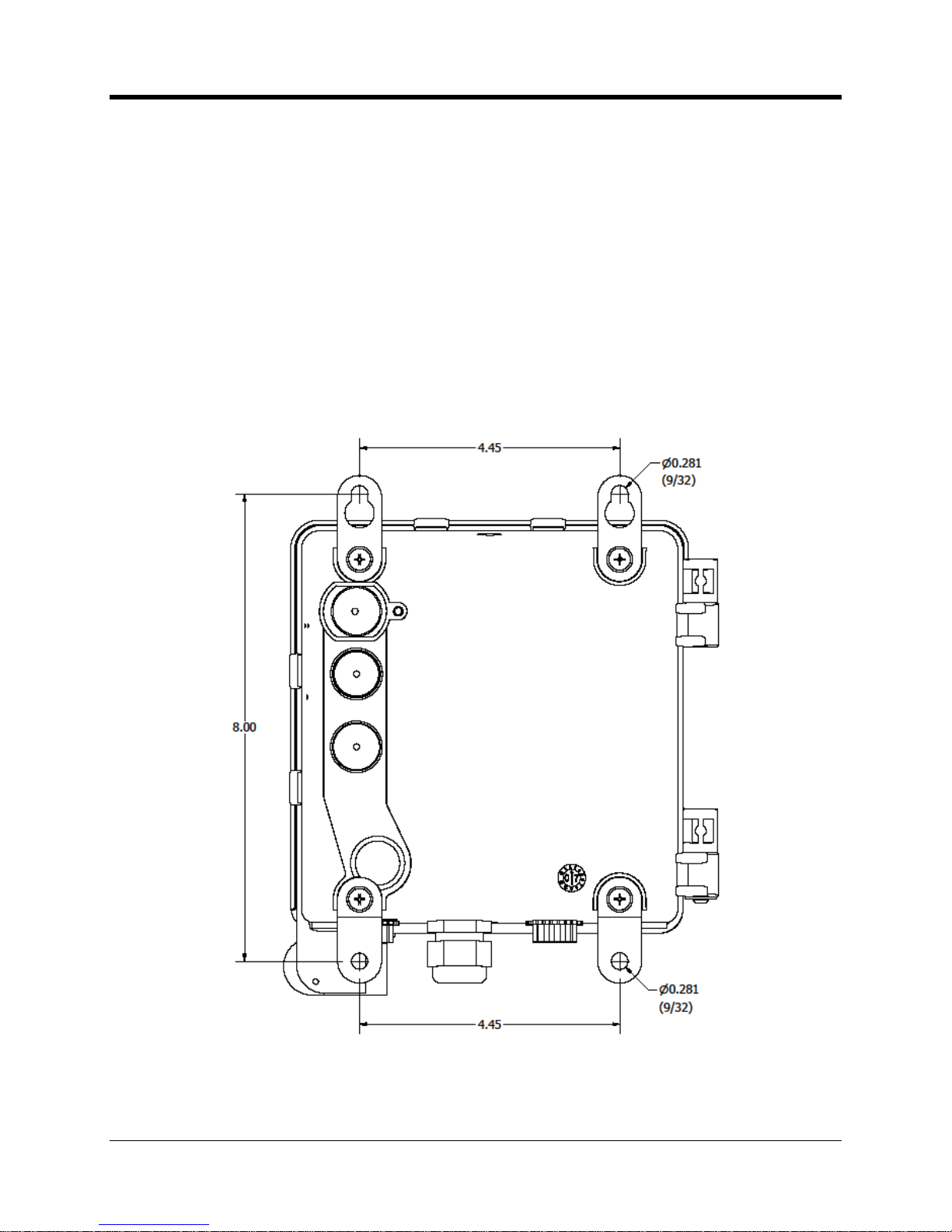
Wall Mounting Tabs and Dimensions
................................
................................
........................
16
Wall Mount Hangers Asse
mbly Sequence
................................
................................
................
17
CNI2 with Universal Mounting Bracket (UMB)
................................
................................
...........
18
Bottom View of the Universal Mounting Bracket (UMB)
................................
.............................
19
Universal Mounting Bracket (UMB) Hole Pattern
................................
................................
.......
19
Pipe Mounting using Collar
................................
................................
................................
.......
20
Pipe Mounting using U
-
Bolts
................................
................................
................................
.....20Enclosure Sealing Options
................................
................................
................................
........
21
Lithium Battery Pack Mounting
................................
................................
................................
..21Alkaline Battery Pack Mounting
................................
................................
................................
.22Disposable Alkaline Battery Pack
................................
................................
..............................
23
CNI2 Board Orientation
................................
................................
................................
.............
24
CNI2 Board and Multiplexer Board
................................
................................
............................
25
CNI2 Board and RS
-
485 Board
................................
................................
................................
.26CNI2 Board with RS
-
485 Board and Multiplexer Board
................................
.............................
27
CNI2 with single RS
-
232 connection to external instrument
................................
......................
28
CNI2 wit
h multiplexer board to support two serial data links
................................
......................
28
CNI2 with conversion board to interface to RS
-
485 capable instrument
................................
....28Configuration using both RS
-
232 & RS
-
485 options
................................
................................
..29Index Base with Magnetic Switches
................................
................................
..........................
30
Pulse Output Board
................................
................................
................................
...................
31
Internal View of the Index Base
................................
................................
................................
.31Rotation Gears within the Index Base
................................
................................
.......................
32
Remote
Pulse Transmitter
................................
................................
................................
.........
33
Location of the Internal Antenna
................................
................................
...............................
34
Antenna Connection to Radio Module
................................
................................
.......................
34
Bottom View with External RF Connector
................................
................................
..................
35
Location of the TAMPER and CALL Switches
................................
................................
...........
36
CNI2 Circu
it Board Layout
................................
................................
................................
.........
37
J1 and J2 Power Connectors
................................
................................
................................
....38Configuration Jumpers
................................
................................
................................
..............
39
Jumper Block JP6 Settings
................................
................................
................................
.......
40
Jumper Block JP3 Settings
................................
................................
................................
.......
40
Capacitor Connection to TB1 (prewired)
................................
................................
...................
41
Serial RS
-
232 Multiplexer Board
................................
................................
...............................
43
Wiring to the Serial RS
-
232 Multiplexer Board
................................
................................
..........
44RS-
485 Conversion Board Connectors
................................
................................
.....................
45
Uncorrected Pulse Output Board
................................
................................
...............................
46
Alarm Input Connectors
................................
................................
................................
............
47
Alarm / Pulse Input Terminal Block TB4
................................
................................
....................
48
CNI2 Power Connections
................................
................................
................................
..........
50
AC Power Adapter
................................
................................
................................
....................
51
External Power Tie
-
In Block
................................
................................
................................
......51Typical Solar Power System
................................
................................
................................
.....52Serial
Port Terminal Block TB2
................................
................................
................................
.53Typical SIM Card
................................
................................
................................
......................
53
Installation of the SIM Card
................................
................................
................................
.......
54
Page 9

CNI2
O
perating and Installation
Guide
8
Serial and USB Programming Cables
................................
................................
.......................
56
MP32
®
Login Screen
................................
................................
................................
.................
57
MP32
®
Device Selection Screen
................................
................................
...............................
57
Programming Port Configuration Screen
................................
................................
...................
58
CNI2 Main Configuration Screen
................................
................................
...............................
59
Standard A
larm Descriptions
................................
................................
................................
.....63Configuration of an Alarm Input
................................
................................
................................
.64Configuration of a “Special Purpose” Input
................................
................................
................
66
Configuration of a Pulse Counting Input
................................
................................
....................
67
Configuration of a “Special Purpose” Output
................................
................................
.............
70
Options Screen
................................
................................
................................
.........................
71
“Route To” Port Selection in Transparent Mode
................................
................................
........
75
Serial Port Configuration Screen
................................
................................
...............................
77
Hardware Flow Control
................................
................................
................................
.............
78
DTR Detection Jumper
................................
................................
................................
..............
82
CDMA Cellular Configuration Screen
................................
................................
........................
85
Installation of the SIM Card
................................
................................
................................
.......
90
GSM Cellular Configuration Screen
................................
................................
..........................
90
Call Scheduling Screen
................................
................................
................................
.............
94
Server Mode Screen
................................
................................
................................
.................
96
Attaching the Programming Cable
................................
................................
.............................
97
OTA Device Selection Screen
................................
................................
................................
.
100
Example of Error Code “35” Display
................................
................................
........................
103
LED Error Codes 11 thru 19
................................
................................
................................
....
104
LED Error Codes 21 thru 39
................................
................................
................................
....
105
LED Error Codes 41 thru 59
................................
................................
................................
....
106
LED Er
ror Codes 61 thru 79
................................
................................
................................
....
107
Example of Timed Sampling
................................
................................
................................
...
108
Example of Switch Bounce
................................
................................
................................
......
109
Example of Debouncing Process
................................
................................
............................
110
Typical Form
-
A and Form
-
C (KYZ) Connections
................................
................................
.....
111
Example of Detection of a
Form
-
C Fault
................................
................................
.................
111
Accuracy Errors Using the “Output
-
Follows
-
Input” Feature
................................
.....................
112Delay Errors Using “Output
-
Follows
-
Input” Feature
................................
................................
.
112
Typical CNI2 “AT” Responses
................................
................................
................................
.
113
Received Data (RXD) Detection Jumper
................................
................................
.................
116
Starting the DC
-
2009 System Configuration
................................
................................
............
117
Changing the Data Collection Configuration
................................
................................
............
118
Configuring the SIP Se
rver
................................
................................
................................
......
119
Configuring DC
-
2009 for CSD Connections
................................
................................
............
120
Configuring a Call Schedule
................................
................................
................................
....
121
Defining a Call Profile Name
................................
................................
................................
...
122
Defining a Call Profile
................................
................................
................................
..............
123
Starting the CNI2 Configuration Process
................................
................................
.................
124
Remote Unit Selection Screen
................................
................................
................................
125
Device Type Selection Screen
................................
................................
................................
125
Add Remote Unit Screen
................................
................................
................................
........
126
Remote Unit Configuration General Information Screen
................................
..........................
127
Device Configuration Screen
................................
................................
................................
...
128
Data Input Configuration Screen
................................
................................
.............................
129
Call Information Screen
................................
................................
................................
...........
130
Page 10

CNI2
O
perating and Installation
Guide
9
Hardware Ala
rm Configuration Screen
................................
................................
....................
131
Viewing the Cellular and Hardware Status
................................
................................
..............
136
Cellular and Hardware Status Screen
................................
................................
.....................
137
Starting the Call Diagnostic Dump Utility
................................
................................
.................
138
Using the Call Diagnostic Dump Utility
................................
................................
....................
139
Status and Cellular Information on the Call Dump Screen
................................
.......................
139
Cellular Information Fields
................................
................................
................................
.......
140
Previous Error Codes on th
e Call Dump Screen
................................
................................
.....
140
Power Input Connector Polarities
................................
................................
............................
154
ASCII Conversion Chart
................................
................................
................................
..........
161
Page 11

CNI2
O
perating and Installation
Guide
10
Version 1.00
April 23, 2010
-
Initial release of draft document.
Version 1.01
May 3
, 2010
-
Redefined section breaks.
-
Redefined some text styles to allow automatic inclusion into the table of contents.
-
Added
figure titles to all illustrations
and added a list of figures after the table of contents.
-
Moved battery regulations
statements
and warnings
to
the
beginning of
the
document.
-
Added an auto
-
date field to the cover sheet.
-
Refined and added to the section that deals with programming the unit
.
REVI
SI
ON HISTORY
Page 12

CNI2
O
perating and Installation
Guide
11
“Windows” refers to
Microsoft Windows 2000, XP, Vista and Windows
-7that
are either
registered trademarks or trademarks of Microsoft Corporation in the United States and/or other
countries.
“MV90
®
” is
either
a registered tra
demark
or
trademark
of
Itron
Corporation.
“DC-
2009
®
”
“MP32
®
”
and “
InvisiConnect
®
”
are either registered trademarks or trademarks of
Honeywell International.
Other brands and product names are trademarks or registered trademarks of their respective
holder
s.
“Metretek” is a reference to a business that produced
data logging and telemetry products
between 1977 and 2008. Metretek was acquired by Mercury Instruments in 2008. The
Metretek name appears in this document as a reference to legacy products and pr
otocols,
which are still in use today.
For additional information or questions regarding Mercury Instruments, please contact
a Product
Support Specialist
or visit our website.
Honeywell |
Mercury Instruments
3940 Virginia Ave. • C
incinnati, Ohio 45227 USA
Phone 513
-
272-1111 • Fax 513
-
272-0211
www.mercuryinstruments.com
TRADEMARKS
AND COPY
RIGHTS
Page 13
CNI2
O
perating and Installation
Guide
12
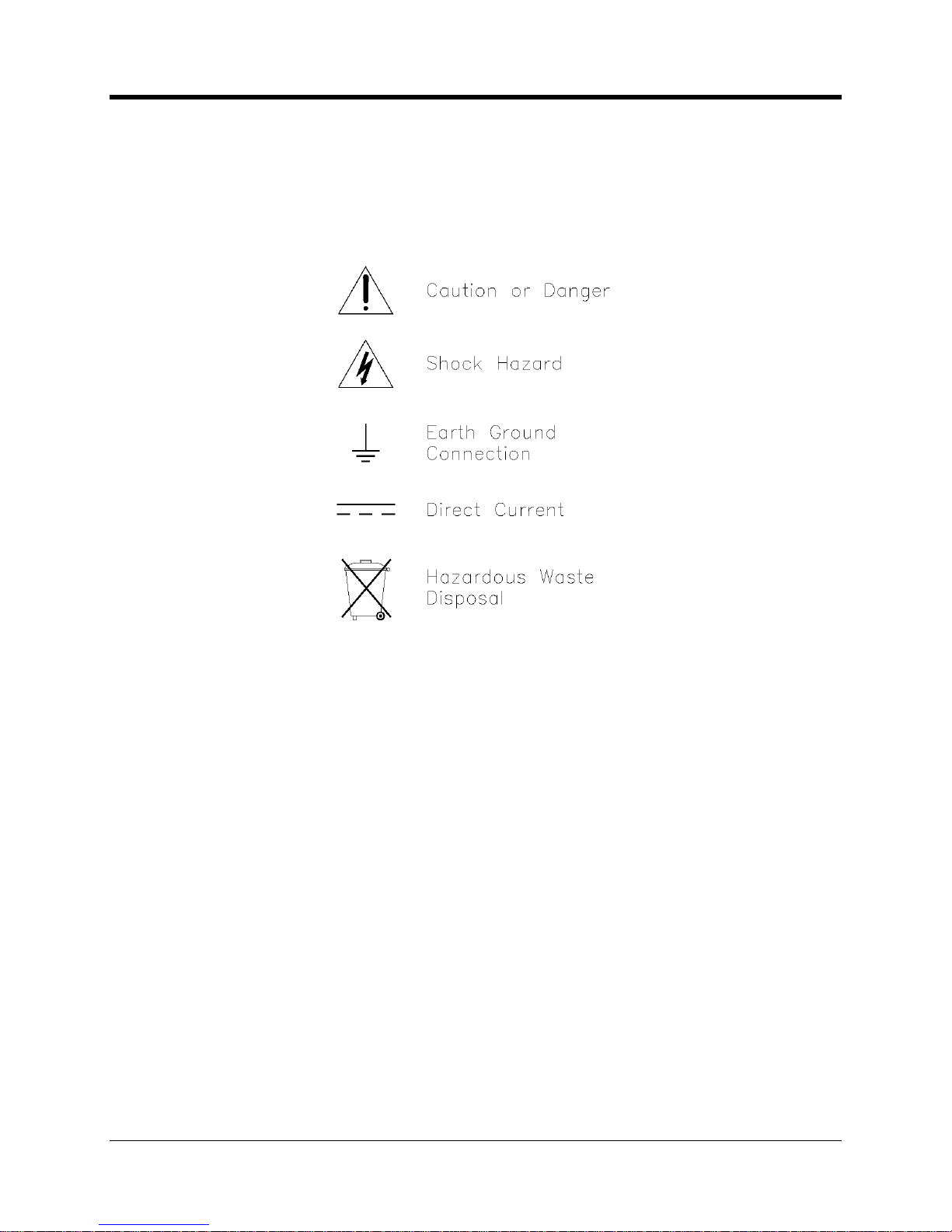
The following symbols may be found within the text of this document, or
may
be marked direct
ly
on the equipment.
Denotes an information item
Denotes a user action item
Denotes an example line
Caution or Danger:
Alerts the operator to special precautionary actions that may be required,
or danger hazards that exis
t or have the potential to exist.
Shock Hazard:
Alerts the operator to an electrical shock hazard condition that exists or could
potentially exist.
Earth Terminal:
Symbol that indicates earth ground. A copper rod buried in the ground is a
common examp
le of an earth ground connection, although these can take various forms.
Reference your local electrical code regulations for detailed information.
Direct Current:
Internationally recognized symbol that represents voltage in the form of direct
current. A
common example of a direct current (DC) source is an automotive car battery.
Hazardous
Wa
ste Disposal
:
Alerts the operator that the equipment or component thus labeled
is not to be disposed of without special consideration to the hazardous waste that it
contains.
Compliance is necessary to ensure that national, state, and local community legal statutes are
not violated.
SYMBOLS
AND
ICONS.
Page 14

CNI2
O
perating and Installation
Guide
13
Warning
This product contains a radio
-
frequency transmitter,
Motorola Model g24
-
L, FCC ID # IHDT56HQ1,
(GSM
-
Equipped CNI2)
The co
mbined cable loss and antenna gain must not exceed +6.8 dBi (850 band),
+1.9 dBi (900 band), +7.7 dBi (1800 band) or +2.2 dBi (1900 band). Total system
output must not exceed 2.0W EIRP in the 1900 band in order to comply with the
EIRP limit of 24.232.
The
product must be installed in a manner that
provide
s
a minimum separation
distance of 20cm (8”)
or more between the antenna and
users and persons and
must not be co
-
located or operat
e
in conjunction with any other antenna or
transmitter
to satisfy expos
ure requirements.
.
Warning
This product contains a radio
-
frequency transmitter,
Motorola Model
c24,FCC ID # IHDT56JE1
,
(CDMA
-
Equipped CNI2)
The combined cable loss and antenna gain must
not exceed +5.3dBi (800 band).
The combined cable loss and
antenna gain must not exceed +4.2dBi and total
system output must no
t exceed 2.0W EIRP in the
PCS (
1900
)
band in order to
comply with the EIRP limit of 24.232
(b).The
product must be installed in a manner that
provide
s
a minimum separation
distance of 2
0cm (8”)
or more between the antenna and
users and persons and
must not be co
-
located or operat
e
in conjunction with any other antenna or
transmitter
to satisfy exposure requirements.
.
FCC Warning:
This device complies with Part 15 of the FCC Rules. O
peration is subject to the
following two conditions: (1) This device may not cause harmful interference, and
(2) this device must accept any interference received, including interference that
may cause undesired operation.
Page 15

CNI2
O
perating and Installation
Guide
14
Caution
Disposal of lithium battery cells is strictly regulated in most areas as hazardous waste
material. Consult your regional waste disposal authority to ensure full compliance
with legal statutes when disposing of cells.
Warning
Transp
ort of primary cell lithium batteries (even when fully discharged) of this type is
strictly forbidden on passenger aircraft. Cargo shipment of batteries via UPS, FedEx,
etc., requires special shipping containers, packing, and paperwork to be completed.
Domestic Requirements
Class
-
9 is a general class designation by the DOT and has specific packaging instructions.
Lithium primary cells are ‘Class
-
9’ if they contain more than 5.0 grams of lithium. This is
applicable to
the lithium battery pack
s
intended
for
use
with the
CNI2
.
Specific requirements are applicable to Class
-
9 shippers:
Product handlers must be tested and certified. Packaging must meet Group II requirements and
boxes must be tested by UN specification. Packaging must be clearly marked to
indicate:
Lithium batteries, UN3090, PG II, Number of packages, Emergency phone number, Shipper
certification.
MSDS information must also be included within the package.
Additional requirements may apply, or come into force in the future. Please co
nfirm all
requirements in advance with your shipper.
IMPORTANT BATTERY IN
FORMATIO
N
Page 16

CNI2
O
perating and Installation
Guide
15
The Honeywell
CNI2 is a pulse accumulator (data logger) and serial data communications
product with an integral cellular radio transceiver. Pulse signal inputs (dry contact) and ala
rm
inputs can be supplied from an external electronic corrector
or other measurement device
. An
index base option with both a mechanical index display and pulse switch output is available.
Serial data communications with a cor
rector
or similar instrument
are also possible using either
an RS
-
232 or RS
-
485 connection.
A variety of power o
ptions are also available
. These include alkaline battery, lithium battery, or
an external source such as solar or AC mains.
Numerous pulse counting inp
uts and alarm trigger inputs are supported.
Optional meter index base enables direct mounting onto a gas meter.
Several mounting options provide flexibility to mount to a wall, pipe, meter, etc.
Cellular radio service options include conventional GSM and C
DMA. Additional radio
options are also available to service special market
needs
.The internal antenna feature conceals the nature of the wireless device. Where signal
strength is a concern, external antenna options are also supported.
Various power opt
ions are available, including alkaline battery, lithium battery, or
connections for external sourced power. External power can be either AC mains or
solar.
The enclosure is field proven durable and UV resistant against weather effects.
Over
-
the-air firmw
are update capability allows for new feature enhancements as they
become available.
CSA Hazardous area certification, Class I, Div
-
2, Group
-
DPTCRB cellular network approvals
FCC Part 15
(B), 22, 24
Measurement Canada
Metrology
Operational
temperature range
-
22 to +158 F (
-
30 to +70 C)
CNI2
OVERVIEW
CNI2
FEATURES
CERTIFICATIONS
Page 17
CNI2
O
perating and Installation
Guide
16
INSTRUMENT MOUNTING
OPTIONS
A number of options are available for conveni
ent
installation of the CNI2 product. These should
be clearly specified at the time of
order to ensure
that the field t
echnician
has everything he or
she needs to install the product.
WALL MOUNTING
Where a flat wall surface is available, such as on the side of a building or shed, stainless steel
“hangers” can be utilized.
Illustrated below is the rear
view of a CNI2, along with associated
mounting dimensions.
Wall Mounting Tabs and Dimensions
MECHANICAL ASSEMBL
IES
Page 18

CNI2
O
perating and Installation
Guide
17
Assembly sequence for the backside hangers is shown in the illustration below. The lock
-
washer contacts directly with the enclosure, then the hanger, the f
lat washer, and lastly the
screw to secure. Tighten the screw until snug, but do not over
-
tighten.
Wall Mount Hangers Assembly Sequence
METER INDEX BASE
Where it is desired to have an index base mounted directly to a meter, the UMB
(
Universal
Mount
ing Bracket
)
option is available. The
a
dvantages of
this
package are that the entire
instrument can be mounted without any concerns about routing external meter pulse signal
wires. Mounting of the UMB index base is possible on rotary, turbine, and diaphr
agm gas
meters that have a rotating instrument drive output. This includes American, Rockwell, Romet,
Roots, or Schlumberger meters.
The UMB housing may be rotated about the base plate so that the instrument and index will
face in
any of the four direct
ions. R
emov
e
all four screws which attach the base plate to the
bracket housing.
Replace and tighten the four screws after you have repositioned the UMB
housing.
Page 19

CNI2
O
perating and Installation
Guide
18
CNI2 with Universal Mounting Bracket (UMB)
Page 20

CNI2
O
perating and Installation
Guide
19
The bottom side of the UMB meter index i
s seen below, along with the ‘wriggler’ mechanism.
Bottom View of the Universal Mounting Bracket (UMB)
The following illustration provides reference dimensions for the base plate.
Universal Mounting Bracket (UMB) Hole Pattern
Page 21
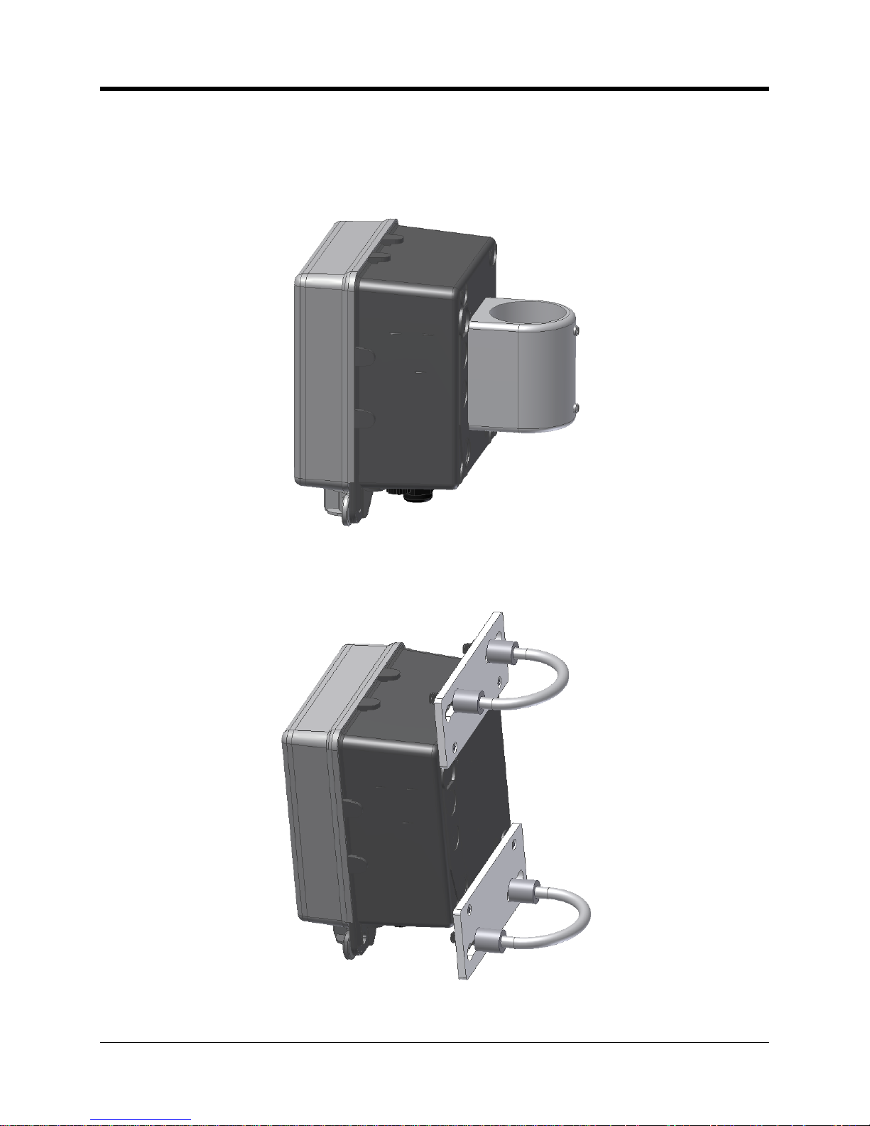
CNI2
O
perating and Installation
Guide
20
VERTICAL PIPE MOUN
TING
Another mo
unting option available for the CNI2 is the pipe
-
mount. This adaptor will accept a 2
⅜” (2.375
”
) diameter galvanized pipe, and is secured in place with a pair of Allen
-
head set
-
screws.
Pipe Mounting using Collar
Illustrated below is a U
-
Bolt mounting
option.
T
his is optimized for metal pipe w
ith an outside
diameter of 2
⅜” (2.375
”).Pipe Mounting using U
-
Bolts
Page 22
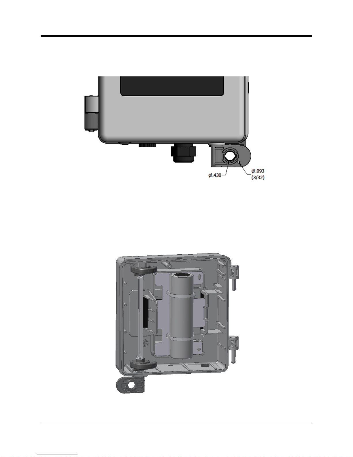
CNI2
O
perating and Installation
Guide
21
ENCLOSURE SEALING
Sealing of the enclosure is readily accomplished using either a conventional lock through the
larger
hole
or a securit
y wire seal through the smaller hole.
Enclosure Sealing Options
INTERNAL BATTERY POW
ER OPTIONS
Several battery configurations are available to best serve the particular applications. Shown
below is the dual
-
cell lithium power pack. This
pack insert
s onto
the enclosure door with the
right
-
side
of the
metal plate tilted inwards first, and then snapping secure on the left side.
Removal is the opposite, and it is a simple matter of pressing outwards against the plastic lever.
Lithium Battery Pack M
ounting
Page 23
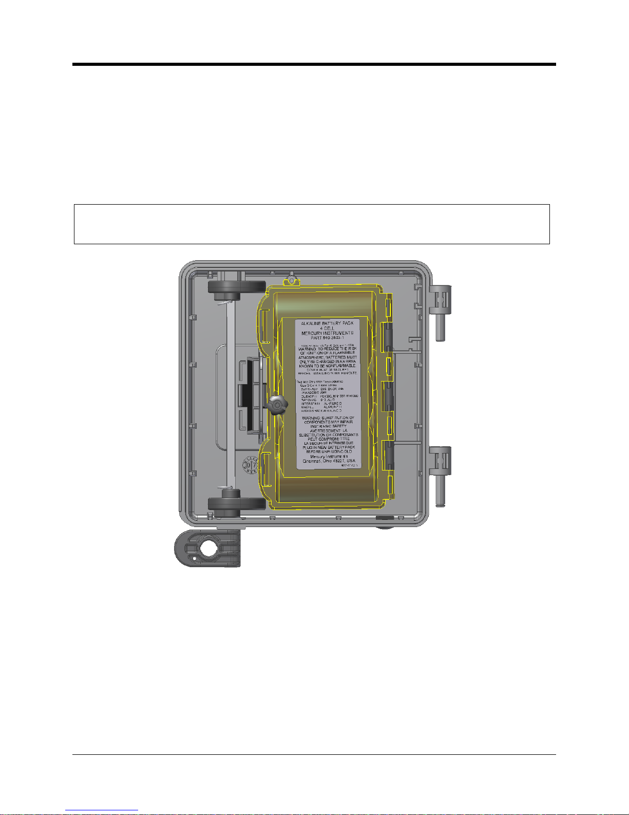
CNI2
O
perating and Installation
Guide
22
A larger quad
-
cell lithium pack is also available for double the capacity of the dual cell type.
Refer to the specifications section at the end of this manual for a comprehensive listing of
battery pack options their part numbers.
Alkaline batt
ery packs are available in either disposable form, or with a molded plastic housing
that permits direct replacement of individual cells. The illustration below shows the plastic
housing model mounted onto the enclosure door. Although the molded battery h
ousing has a
higher initial cost, it offers the advantage of replacement cell availability from numerous local
suppliers.
NOTE
When replacing alkaline batteries, only use new fresh cells from the same supplier and
having equivalent part numbers.
Alk
aline Battery Pack Mounting
Page 24
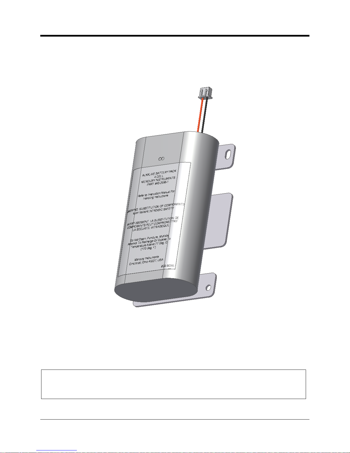
CNI2
O
perating and Installation
Guide
23
Alkaline cells are also available in a completely disposable package option. After the service life
of the battery pack has expired, the user simply disposes of the entire assembly, including the
metal bracket.
Refer to the
specifications section of this manual, or the control drawing for a compiled listing of
approved battery packs.
Disposable Alkaline Battery Pack
To avoid loss of system power to the CNI2 board during battery changes, it is recommended
that the fresh
batteries be connected to the available J1 or J2 connector before removal of the
old battery pack. This is a hot swap method that is permitted for the brief period during which
batteries are to be replaced.
IMPORTANT NOTE
Physical space is not availabl
e within the enclosure to permit two battery packs to be
permanently installed simultaneously. In addition, parallel battery packs would violate
hazardous area safety approvals for this product.
Page 25

CNI2
O
perating and Installation
Guide
24
INTERNAL CIRCUIT BOA
RDS
The f
ollowing is a brief summary
of the CNI2 internal circuit boards and various options.
Specific details of each board or option are described in more detail later.
CNI2 Board
Illustrated below is the CNI2 board with the cellular radio in the center, and various connectors
around
the perimeter. This represents the most common model that is supplied with no
accessory boards and no index base.
CNI2 Board Orientation
Page 26
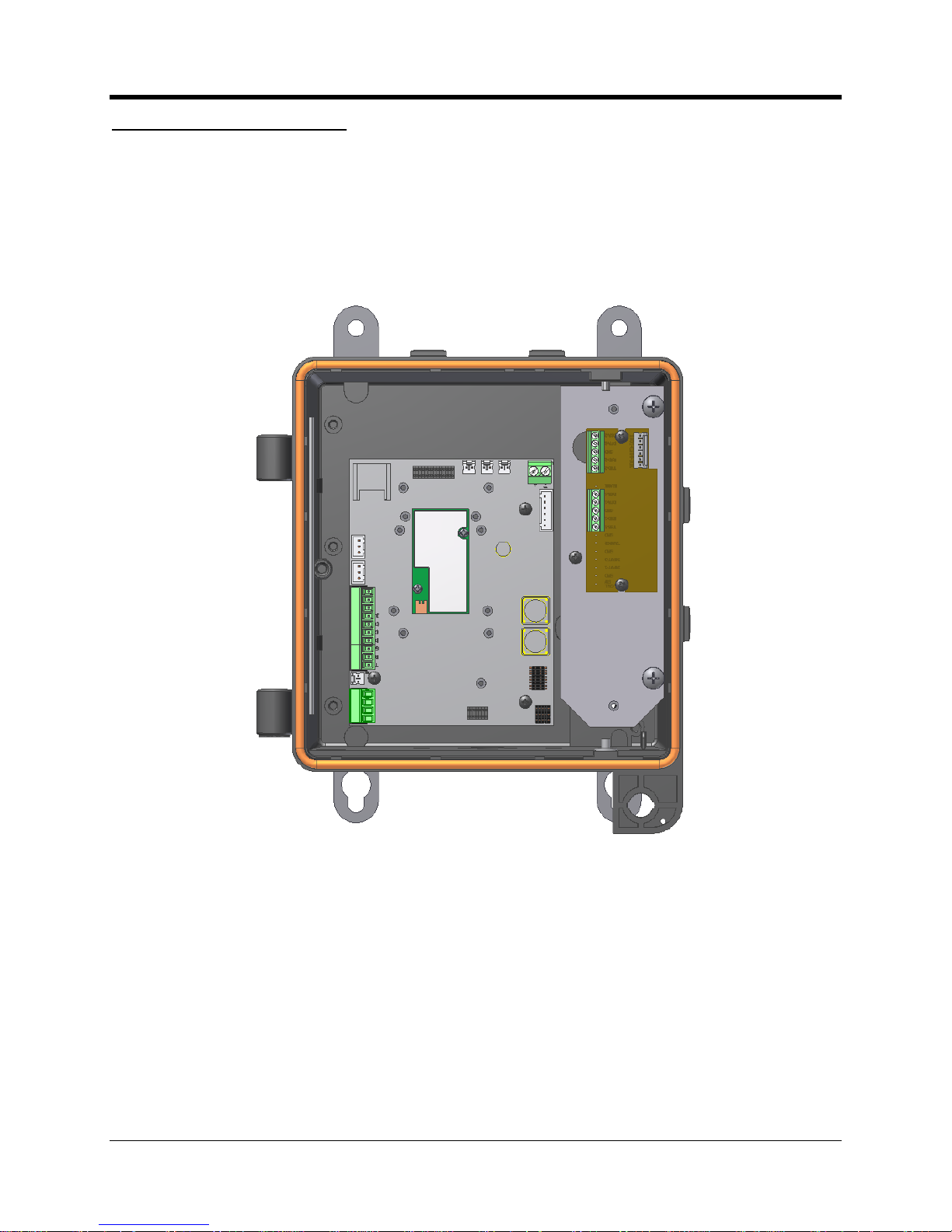
CNI2
O
perating and Installation
Guide
25
Serial Port Multiplexer Board
One of the accessory board options available is the serial port multiplexer. Thi
s enables the
CNI2 serial data port to access two external devices (electronic correctors for example). Two
terminal blocks provide the connection point for serial data cable.
A metal base plate is included for the purpose of securing the board into posi
tion as seen in the
illustration.
CNI2 Board and Multiplexer Board
Page 27
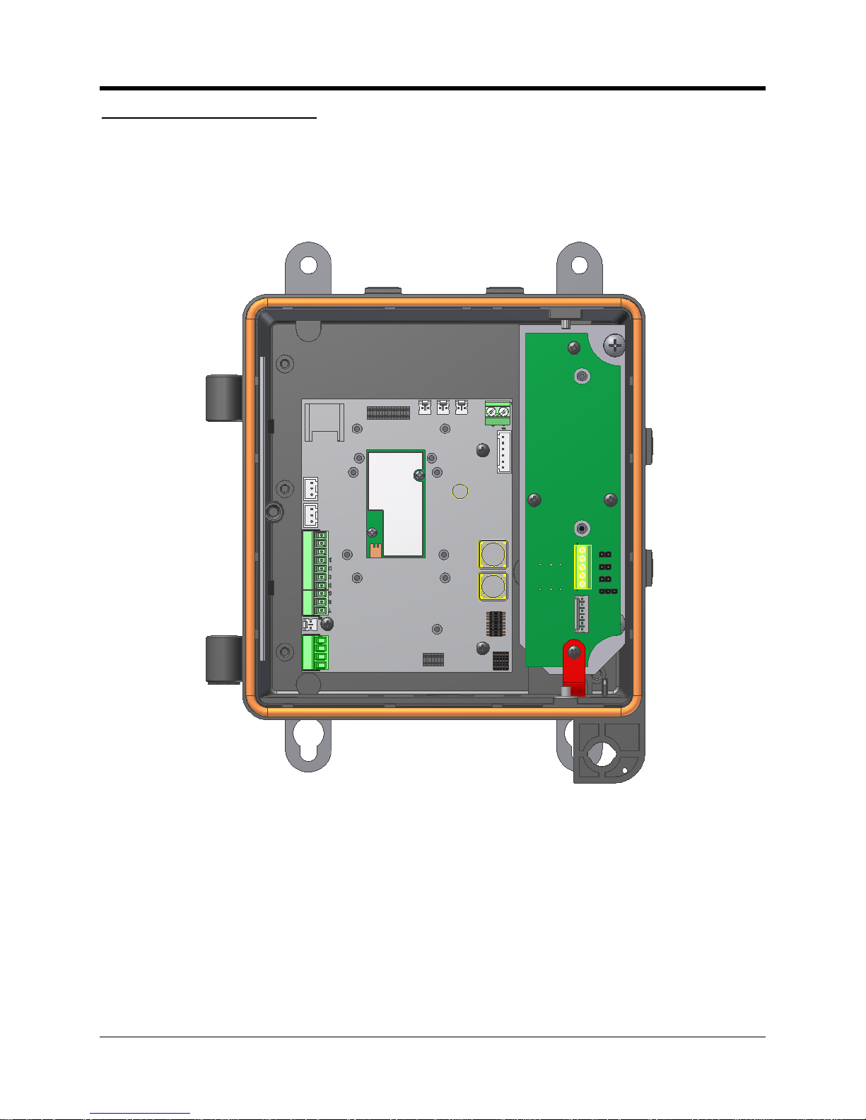
CNI2
O
perating and Installation
Guide
26
RS-485 Serial Data Converter
Another accessory option available is the RS
-
485 conversion board. RS
-
485 is somewhat
similar to the RS
-
232 standard in that it is a wired transmissio
n line for serial data exchange.
The RS
-
485 standard offers several advantages over RS
-
232 in terms of cable length distance,
noise immunity, multi
-
node drops, etc.
CNI2 Board and RS
-
485 Board
Page 28
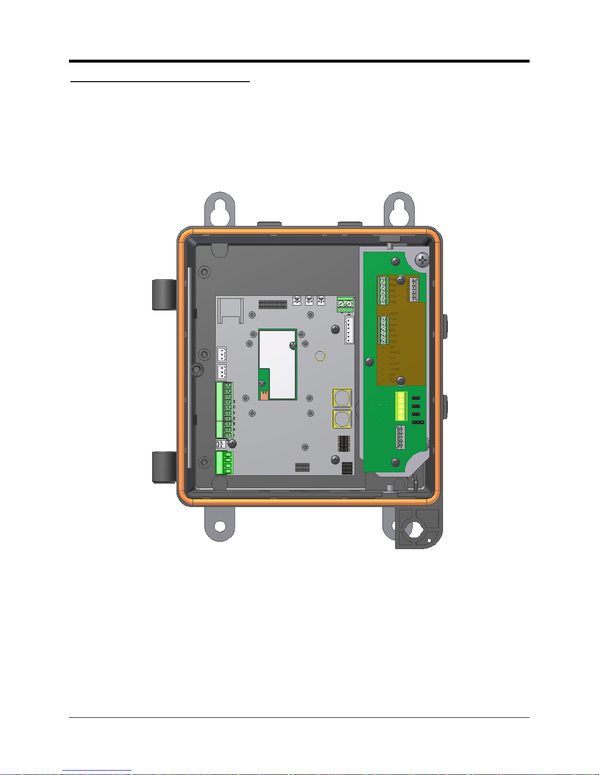
CNI2
O
perating and Installation
Guide
27
Serial Multiplexer & RS
-
485 Boards
It is possible to su
pport both the RS
-
232 serial data transfer and RS
-
485 transfer by switching
channels with the multiplexer board. An example of where this might be of value is when there
is a corrector that requires an RS
-
232 data link, and a pressure transducer that requi
res an RS
-
485 connection. Take note however that serial data exchange can take place only on a channel
at a given time.
CNI2 Board with RS
-
485 Board and
Multiplexer Board
Page 29
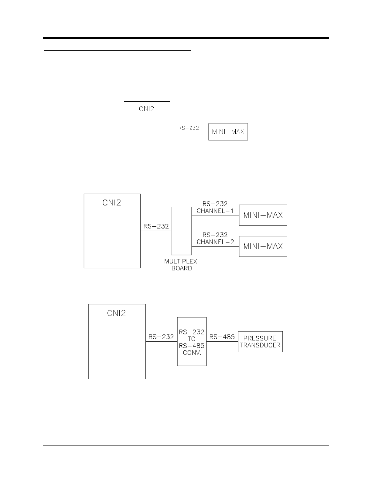
CNI2
O
perating and Installation
Guide
28
Summary of Serial Data Connection Scenarios
The simple block diagrams bel
ow provide an overview of serial data connection possibilities for
the CNI2. For the sake of convenience, end devices are shown here as being
a
‘Mini
-
Max’
corrector
anda‘Pressure Transducer’. The Mini
-
Max has an RS
-
232 port and the Pressure
Transducer
has
an RS
-
485 port.
CNI2 with single RS
-
232 co
nnection to external instrument
CNI2 with multiplexer board t
o support two serial data links
CNI2 with conversion board to interfa
ce to RS
-
485 capable instrument
Page 30
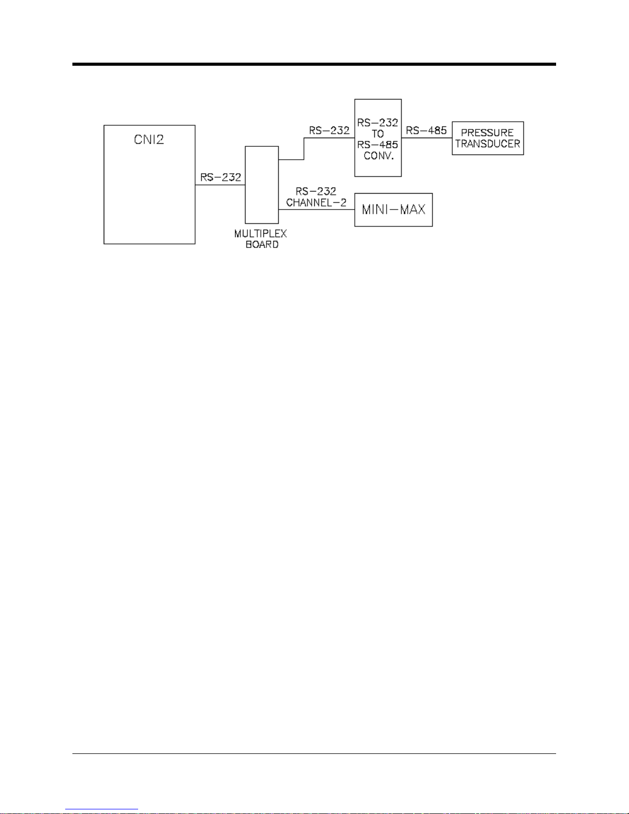
CNI2
O
perating and Installation
Guide
29
Configuration using bot
h RS
-
232 & RS
-
485
options
Page 31

CNI2
O
perating and Installation
Guide
30
CNI2 INDEX BASE
When the UMB index mount option is included with the instrument, a rot
ating
magnet and
several
magnetic
sensor switches will be present inside the enclosure as seen below.
For
convenience, wires from t
he senso
r switches are pre
-
wired from the factory to the pulse
counting input terminal block TB4. In the unlikely event that one of the two reed switches should
fail, the redundant input channel will continue to register accurate counts.
The illustration below s
hows the CNI2 with the rotary magnet and dual reed switches.
Index Base with Magnetic Switches
For the sake of clarity
this
illustration
does not
show the routing of wires from the sensor
switches.
Page 32

CNI2
O
perating and Installation
Guide
31
Another
option is the Uncorrected Pulse Output boa
rd, as seen below. This provides an
additional dry
-
signal pulse output that allows for connection to an external pulse counting
instrument.
Pulse Output Board
For the sake of clarity
this
illustration
does not
show the routing of wires from the sensor
switches.
Illustrated below is the UMB index without the front covers
or
enclosure housing. To change the
direction of rotation, it is first necessary to remove the odometer. This is accomplished by
removal of the screw in the top left corner, after w
hich the odometer pulls straight out.
Internal View of the Index Base
Page 33

CNI2
O
perating and Installation
Guide
32
A small Allen wrench tool is included with the index. Loosen the set screws on the top and
bottom miter gears and swap the gear that engages. Shift the gear set upwards for meter
s with
CW rotation and down for meters with CCW rotation.
See
the gear detail drawing below.
After
the gears are securely set, check for good gear engagement that is neither too loose
(causing
gear skipping) or too tight (causing gear binding)
.
Then rei
nstall the odometer
.
Rotation Gears within the Index Base
As a final note, it is also possible to change the number of digits visible on the mechanical
odometer
using
horizontal sliding “windows”. Up to three digits can be masked
-
off from the right
s
ide, and/or up to three digits from the left side.
Page 34

CNI2
O
perating and Installation
Guide
33
OPTIONAL REMOTE PULS
E TRANSMITTER
Some applications may not be suitable for a direct mount index on the CNI2 enclosure, due to
available space or other reasons. Where this is the case,
Honeywell
also o
ffers a remote pulse
transmitter with mechanical index display. Pulse switch wiring can then be routed into one of
the cable fittings on the CNI2 enclosure.
Contact a Honeywell
Product Support Specialist for additional details and ordering options.
Remote Pulse Transmitter
Page 35

CNI2
O
perating and Installation
Guide
34
ANTENNA OPTIONS
For the majority of site installations the most convenient and cost effect choice are CNI2’s with
the internal cellular antenna as seen in the illustration below. This is a five inch length
rectangular shaped
circuit board (light blue color) that is mounted directly to the left inside wall
of the enclosure. Connection to the radio is via a short coaxial cable with an ‘MMCX’ type
connector on the end.
Location of the Internal Antenna
If it becomes necessa
ry to disconnect the cable from the cellular radio, take care to firmly grasp
the metal end of the MMCX
connector
housing and pull straight out. Never pul
l directly on the
cable itself or bend the connector.
Antenna Connection to Radio Module
Page 36

CNI2
O
perating and Installation
Guide
35
Where
cellular signal reception is problematic, due to either terrain or proximity to cellular
towers, it may be necessary to utilize an externalantenna instead. This option is available in
the form of a bulkhead N
-
Fitting (jack or female) mount as seen in the
illustration. An external
antenna can then be elevated as required and directionally pointed to the nearest cell tower.
Bottom View with
External
RF Connector
Page 37

CNI2
O
perating and Installation
Guide
36
TAMPER DETECT & CALL
SWITCH OPTIONS
The figure below illustrates where two magnetic det
ect switches have been added to the CNI2.
At the bottom left corner is a seen a small white
magnetic switch
which has been wired into the
J9 connector. This enables a
field t
echnician to swipe
a hand
-
held magnet
wand
(part no. 20
-
7286)
near
bottom left s
ide with in order to initiate a call. In cases where the CNI2 enclosure is
sealed with a lock or wire seal, this form of call trigger is very convenient.
Location of the TAMPER and CALL Switches
The TAMPER switch is seen in the upper left
-
hand corn
er. Not shown is an actuating magnet
attached to the door. When the door isopened the switch activates and can generate an
immediate call into the central office, or the event will be reported on the next scheduled call.
Page 38

CNI2
O
perating and Installation
Guide
37
CIRCUIT
BOARD CONNECTORS & J
UMPERS
This chapter
identifies the
locations of important components, connection points, and jumpers
on the CNI2 and a
ccessory boards.
CNI2 Circuit Board Layout
ELECTRICAL ASSEMBLIE
S
Page 39

CNI2
O
perating and Installation
Guide
38
Cellular Radio Module
The cellular radio module
is manufactured by M
otorola and will be either a
g24-L
(GSM) or c24
(CDMA)
. It is possible to remove and install a new module in the event that the original
module
fails
. Two small screws must be removed first, the radio pulled straight away from the board,
and the nylon sp
acers retained for later use. This type of operation is best performed within an
office setting, and even then only when absolutely necessary. The high density electrical
connector on the radio is delicate and can easilybe damaged unless great care is t
aken during
insertion and removal.
SIM Card Socket
This connector holds the
cellular radio SIM card for GSM
-
equipped models of the CNI2.
SIM
cards are not required for CDMA radios.
Reset Jumper JP4
If it is necessary to perform a complete reset operat
ion, use a small blade screwdriver or coin to
short out the two pins of JP4.
Caution:
A reset will cause
all
pulse data to be lost and theunit’s time
-of-
day to be reset. This
will cause the CNI2 to call the data collection system to report a “Unit R
eset” alarm.
When possible, first place a call to download accumulated interval data to
the central
office
prior to performing a reset.
Power Connectors J1 & J2
These connectors are intended for connection to power sources. Both connectors are ident
ical
in function, and allow for the hot
-
swap of batteries without the loss of power to the CNI2 board.
J1 and J2 Power Connectors
Page 40

CNI2
O
perating and Installation
Guide
39
Terminal Block TB2
Terminal block TB2 provides for connection to the RS
-
232 serial port
of the CNI2.
This
connector will be prewired at the factory whenever RS
-
485 adaptor or a RS
-
232
multiplexer
board
is installed.
There is more information about the serial port later in this document.
Terminal Block TB4
Terminal block TB4 is
the connec
tion point for pulse
-
counting
or alarm
-
sensing inputs
. If an
index base is provided with the CNI2 then this connector will be prewired
at the factory
.
JP3 & JP6 Jumper Settings
Factory default settings for JP3
and
JP6 are illustrated below. Manipulati
on of these jumpers
allows for special operating modes and test functions. Normally the default settings will not be
altered unless under direct guidance from a Product Support Specialist or perhaps a customized
retrofit kit
supplied by Honeywell.
Conf
iguration Jumpers
Page 41

CNI2
O
perating and Installation
Guide
40
JP6
JUMPER OUT
JUMPER IN
1-2
Not used (storage for spare jumper)
Not used (storage for spare jumper)
3-4
Not used (storage for spare jumper)
Not used (storage for spare jumper)
5-6
*** Enables normal operation
Enables
factory
tes
t mode
7-8
Not used (storage for spare jumper)
Not used (storage for spare jumper)
9-10
*** Directs programming cable to Main
Processor
Directs programming cable to Aux
illiary
Processor
11-12
Disconnects on
-
board pull
-
ups for digital
lines 1, 2, 3, 4, 5
and 8.
*** Connects on
-
board pull
-
ups for digital
lines 1, 2, 3, 4, 5 and 8.
13-14
Disconnects on
-
board pull
-
ups for analog
input lines 1 thru 6.
*** Connects on
-
board pull
-
ups for
analog input lines 1 thru 6.
15-16
Disconnects on
-
board pull
-
ups for dig
ital
lines 6 and 7.
*** Connects on
-
board pull
-
ups for digital
lines 6 and 7.
*** = Recommended setting
Jumper Block JP6 Settings
JP3A-BB-C
1
Not used (storage for spare jumper)
Not used (storage for spare jumper)
2
CNI2
wakes up on change in D
TR serial
input line
***
CNI2
wakes up on change in RXD
serial input line
3
+3.3V / 0V non
-
inverted RXD input on serial
port.
*** ±5.5V inverted (RS
-
232) RXD input on
serial port.
4
*** Allows
CNI2
to shut
-
down the on
-
board 3.6V regulator when not needed
.
Permanently enables the on
-
board 3.6V
regulator. Normally only used for factory
testing or special applications.
5
*** Allows
CNI2
to shut
-
down the on
-
board 3.6V regulator when not needed.
Permanently enables the on
-
board 3.6V
regulator. Normally on
ly used for factory
testing or special applications.
*** = Recommended setting
Jumper Block JP3 Settings
Connector J4
This connector provides direct access when performing a firmware download or configuration
change when using the MP32 software and pro
gramming cable.
Page 42

CNI2
O
perating and Installation
Guide
41
Terminal Block TB1
This terminal block is pre
-
wired to a high density reserve capacitor as illustrated below.
Normally this connection will not be altered, unless under special circumstances and
instru
ctions from Honeywell.
Capacit
or Connection to TB1 (prewired)
Connector
J9
The d
efault function of J9 is to serve as a
CALL
trigger input. Activation of this inpu
t will cause
the CNI2 to immediately call the central office.
Circuit connection is intended for a “dry” contact
switc
h, meaning that it is a simple switch (or transistor) with no drive voltage. In most cases this
will be pre
-
wired
at the factory to a magnetic
sense switch.
This line can also be configured as
an
additional
alarm
-
sensing
input
, a pulse
-
counting input or
a
s an output
.
Connector
J11
The d
efault function of J11 is to serve as a power failure report input. This is useful for AC
mains applications where the loss of power can be reported to the
central office
. Circuit
connection is intended for a “dry” contac
t switch, meaning that it is a simple switch (or transistor)
with no drive voltage.
This line can also be configured as
an
additional
alarm
-
sensing
input
, a pulse
-
counting input or
as an output
.
Connector
J12
The d
efault function of J12 is to serve as
a tamper detect input. If
the TAMPER
option is
ordered then this alarm will trigger
any
time that the enclosure door has been opened.
The
CNI2 can be configured to place an immediate call to the central office when this occurs, or to
simply report the ev
ent on the next scheduled call.
Circuit connection is intended for a “dry”
contact switch, meaning that it is a simple switch (or transistor) with no drive voltage.
Page 43

CNI2
O
perating and Installation
Guide
42
This line can also be configured as
an
additional
alarm
-
sensing
input
, a pulse
-
counting
input or
as an output
.
Connector
J7
There is no d
efault function
forJ7. It can be configured as
an
additional
alarm
-
sensing
input
, a
pulse
-
counting input or as an output
. Circuit connection is intended for a “dry” contact switch,
meaning that it is a
simple switch (or transistor) with no drive voltage.
It can also be defined as a “Special Purpose Output” which allows the CNI2 to use this line to
control some internal function. This is described in more detail later in this document under the
heading
“
Special Purpose Output
”.
Page 44

CNI2
O
perating and Installation
Guide
43RS-
232 MULTIPLEXER BOAR
D
The RS
-
232 multiplexer is shown
below. The connector J3 is pre
-
wired at the f
actory to the
CNI2 board. When
the RS
-
485 board is
not included with the assembly
then both serial ports
are available fo
r connection to external devices. An example might be two ECAT electronic
correctors at a field site.
If
the configuration has both the multiplexer board and the RS
-
485 as part of the system, then
only terminal block TB2 is available for wiring to an ext
ernal RS
-
232 device. TB1 will have been
pre-wired to the RS
-
485 board, which has its’ own connector for external wiring to an RS
-
485
compatible instrument.
Please note that the TXD line isa driven output, RXD is an input, DSR is a driven output, and
DT
R is used as a wakeup trigger. The following page describes the DTR function and wiring
connection in more detail.
Serial RS
-
232 Multiplexer Board
Page 45

CNI2
O
perating and Installation
Guide
44
In many cases
the CNI2
is powered by a
battery
. I
t is necessary to minimize power
consumption wheneve
r possible. The multiplexer board is based upon opto
-
isolators that
consume power when enabled. For this reason the m
ultiplexer board is not powered
except
when in the process of active data exchange. This presents a problem in that the CNI2 will not
be
able to detect serial communications activity when the multiplexer board is powered down.
A simple method to resolve this is to wire the RXD signal coming from the external instrument in
parallel with both the RXD line and DTR input line. The multiplexe
r board is able to detect serial
data flow on the DTR line, even when in low power mode. This then enables the CNI2 board to
wake from low power mode, drive the multiplexer board, and subsequently receive serial stream
data.
The illustration below shows
where the jumper wire is to be installed across the terminal block
positions 2 & 4.
Wiring to the Serial RS
-
232 Multiplexer Board
NOTE
The a
ddition of a jumper wire as seen above is only required on the multiplexer board itself.
A jumper wire sho
uld not be installed directly on the terminal block of the CNI2 board.
Page 46

CNI2
O
perating and Installation
Guide
45RS-
485 CONVERSION BOARD
The RS
-
485 conversion board is shown
below.
External wiring connections are accomplished
using
terminal block TB1. The number of connections will depend upo
n whether the link is half
duplex or full duplex. Although the full duplex wiring method requires two additional wire
conductors, it is typically simpler to deploy and service in the field.
JP1-When installed this jumper places a 120 ohm termination lo
ad on the RX end. For most
installations this jumper should be installed.
JP2-When installed, this jumper places a 120 ohm termination load on the TX end. For most
installations this jumper will not be installed.
JP3-When installed this jumper re
duces the bandwidth of rise and fall transition edges of the
transmit signal to minimize signal reflections (similar to echo’s) on the cable. For most
installations this jumper is not installed.
JP4-Selects half duplex or full duplex mode. Position A+
B is half duplex, and B+C is full
duplex.
NOTE
If you are using half duplex operation you must select the “
RS-485 Half Duplex
” setting on
the
Serial Port Settings
configuration screen.
Honeywell
has a document available that further details the RS
-
485
theory of operation and how
it applies to this particular board. A Product Support Specialist can provide a copy of this
document in PDF format upon request.
RS-485 Conversion Board Connectors
Page 47

CNI2
O
perating and Installation
Guide
46
UNCORRECTED PULSE OU
TPUT B
OARD
This
option provides a single Form
-
C dry contact switch output for connection to other devices
outside of the CNI2. Counts are proportional to those recorded by the other sensor switches
that wire into the CNI2. This board mounts onto the small met
al plate in proximity to the rotating
magnet head as seen
earlier
.
A three position terminal block provides the connection point for external wiring.
Uncorrected Pulse Output Board
Page 48

CNI2
O
perating and Installation
Guide
47
SIGNAL INPUTS & OUTP
UTS
There are a total of sixdigital sign
als on the
CNI2
board that can be used as alarms, status
inputs, pulse
-
counting inputs or control outputs. A later portion of this chapter provides a
technical discussion about how each input is processed.
Each signal has a “Line Number” associated with
it as seen in the next figure. Knowing which
line number correlates with which input signal is necessary when using the MP32 configuration
software. In most applications these lines are preconfigured for the most common data logger
applications, which wo
uld be a 2
-
channel pulse recorder with power supply control and
monitoring. However any of the six signals can be reconfigured as necessary for the
application.
Alarm Inputs
Any of the six signals can be used as alarms or status inputs. These can be
configured in a
number of ways.
Two of these inputs are connected to the TB4 terminal block and the other
four have their own connectors. If any input is configured as an alarm or status input then it
cannot be used to count pulses.
Alarm Input Conne
ctors
Note
-
1: The common or ground circuit connection at J11 is on the opposite pin when compared
to the other three connectors.
Note
-
2: Mating connector type is available from AMP/Tyco Electronics under part number
641190
-2.Note
-
3: Some configur
ations of the CNI2 are pre
-
wired at the factory with a door
-
tamper detect
switch at J12 and a magnetic call switch at J9.
Page 49

CNI2
O
perating and Installation
Guide
48
The “CALL
” input is usually connected to a magnetic switch located inside the unit. You can
activate the switch by placing a stro
ng magnet near this spot on the outside of the enclosure.
Alternatively the switch can be a simple pushbutton switch located inside the unit or protruding
from the wall of the enclosure. Or you can just momentarily short the J9 pins witha screwdriver
or
coin. This switch will cause the CNI2 to immediately call in to the central computer and report
a “Call” or “Mag. Switch’ alarm.
The “
TAMPER
” switch is often a magnetic switch mounted to the side of the enclosure and a
magnet on the door. When the door
is opened the magnet and switch separate and generate
an alarm. This is often used to detect intrusion as well as record service events.
If you wish to use these inputs for any other purpose you can rename them in the data collection
system. For instan
ce you could rename the “Tamper” alarm as “Low Pressure” or “High
Temperature”.
You can also combine the “Call” and “Tamper” inputs together as a Form
-
C (“KYZ”) pair, in
which case the combination is reported as a “Call” alarm to the data collection syste
m. A
Form
-
C switch consists of one normally
-
open and one normally
-
closed switch. If at any time
both are open or closed this is considered a failure and will be reported as a “Tamper” alarm.
The “Power Fail” input is usually used todetect the loss of
ac mains power. When the alarm
goes active this will be reported as an “AC
-
OFF” alarm. When it returns to an inactive state an
“AC-ON” alarm will be reported. Again if you wish to use this input for any other purpose you
can rename it in the data coll
ection system.
In many standard configurations the J7 “Alarm” input can also be used as an alarm or pulse
-
counting input. This input is not reported to the system as any particular alarm but the CNI2 can
still call in immediately if this input goes act
ive or inactive. Usually if this line is programmed as
an input it is used for pulse
-
counting rather than an alarm.
Alarm / Pulse Input Terminal Block TB4
Page 50

CNI2
O
perating and Installation
Guide
49
The inputs on TB4 will be reported as “Alarm
-
1” and “Alarm
-
2” to the data collection system.
Either can be Form
-
A (normally open) or Form
-
B (normally closed). Or they can be combined
as a Form
-
C (“KYZ”) pair, in which case the combination is reported as “Alarm
-
1” to the data
collection system. A Form
-
C switch consists of one normally
-
open and o
ne normally
-
closed
switch. If at any time both are open or closed this is considered a failure and will be reported as
an “Alarm
-
2” alarm.
Pulse Counting Inputs
Any of the six signals can be used as pulse
-
counting inputs, but no more than four can be
co
nfigured this way because that’s all the data collection system will accept. If any input is
configured as a pulse
-
counting input then it cannot be used as an alarm or status input. Pulse
-
counting inputs can be either Form
-
A, Form
-
B or Form
-
C switches.
Outputs
Any of the six signals can be
configured as outputs. These are low
-
level (+3.3V) logic signals
with very low current (2 mA) capabilities. In many cases these signals will need additional
amplification or conversion by external equipment.
-
Outp
ut Under Host Control
: This configuration can be used to
control external equipment from
the central office, such as a warning light, an audio alarm or a pump. This isonly supported
when using the “Relay Settings” feature in the
DC-2009
®
data collection
system. The output is
changed to the new setting only after a successful call.
-
Output Follows Input #”:
In this configuration the output follows any one of the inputs
(“r
epeater”)
. This allows other external equipment to have access to the same pulse
or alarm
information that is being processed by the CNI2.
WARNING
An output has strict limitations with respect to voltage and current.
See the specifications section to avoid damage to the
CNI2
board.
Page 51

CNI2
O
perating and Installation
Guide
50
POWER SUPPLY OPTIONS
Illustrated below is a port
ion of the CNI2 board. TB1 is prewired at the factory to a high density
capacitor element to support peak load demands when operating the cellular radio. J1 and J2
are the power connectors for the CNI2. Additional details follow.
CNI2 Power Connect
ions
Connectors J1 & J2 are electrically equivalent, and it does not matter which of the two is used
for attachment to the power source. For a batterypowered application it is recommended that
the fresh pack be plugged into an available connector
first
before disconnecting the depleted
pack.
Extending Battery Life
The CNI2 has been designed to provide long service life when operating from batteries. Total
battery life is influenced by two factors in the CNI2; continuous background current and high
curr
ent draw during cellular calls. The background current can be minimized to a certain extent
by using fewer pulse input connections and using normally
-
open (Form
-
A) contacts for pulse
and alarm sensing. High current draw depends on the number and duration
of cellular calls
made. This can be minimized by ensuring the CNI2 has strong cellular reception (which
minimizes call retries) and by limiting the number of regular scheduled calls to the extent
practical.
Low Battery Detection
The voltage level at whi
ch a low
-
battery condition is triggered can be changed using the MP32
programming software
.
Normally the programming template provided by Mercury will have a
default value optimized for the application.
Page 52

CNI2
O
perating and Installation
Guide
51
AC MAINS POWER CONFI
GURATION
Where AC power is r
eadily available, as is the case at some sites, then a power adaptor can be
used to supply the necessary voltage. Requirements for the power adaptor are that it be
capable of sourcing 1 ampere of current at 5.0 volts DC. For Class I, Div. 2 locations, th
is will
require special consideration to ensure that the rules stipulated by NEC and equivalent
Canadian wiring codes for hazardous locations are strictly adhered to.
AC Power Adapter
The output voltage from the power adaptor will be wired into a smal
l terminal block as illustrated
below. It may be necessary to check with a voltmeter which wire is positive and which is
negative coming from the power adaptor.
Polarity of the terminal block connection will be apparent from the opposite end wire colors
in
that Red is positive and Black is negative. In the event that a reverse connection is made by
accident, no harm will be caused to the electronics aside from the fact that the CNI2 will not
power as expected.
External Power Tie
-
In Block
A lithium o
r Alkaline battery pack can be connected to the vacant J1 / J2 power connector to
supply continuous power in the event of AC mains failure. Lithium batteries have a longer
‘shelf
-
life’
as compared to alkaline batteries
, and are
normally regarded as the su
perior choice
for long term backup applications.
Page 53

CNI2
O
perating and Installation
Guide
52
SOLAR POWER CONFIGUR
ATION
Solar power is also a possibility, although it will be necessary to also provide a voltage charge
regulator and lead acid battery as seen in the illustration. Wiring to the termin
al block illustrated
previously will be the same as was the case for the AC mains application. The lead acid battery
serves as the backup source during the evening and cloudy days. Correct sizing of the solar
panel and lead acid battery are necessary for
a given territorial region. Application notes are
available from solar panel suppliers to assist in the process of sizing the panel and battery.
Typical Solar Power System
SERIAL PORT CONNECTI
ONS
-
TB2
In addition to processing alarms and pulse data
, the CNI2 can act as a “transparent” modem.
This allows the central computer to communicate directly with a device connected to the CNI2’s
RS-232 serial port. Most applications for the CNI2 being used as a cellular modem will be with
a Mercury corrector
instrument. Other configurations are certainly possible as well, to support
3rd party instruments such as transducers, odorizers, etc.
The serial port consists of signals with traditional EIA (RS
-
232) levels of ±
5
V. Recommended
cable length should not e
xceed 15 feet, and may need to be shorter at higher bit rates. All serial
parameters are configurable using the MP32 configuration program.
There are also several non
-
inverted logic
-
level signals that are used to connect directly to other
instruments tha
t have a similar port. In most cases these signals will be prewired at the factory.
Page 54

CNI2
O
perating and Installation
Guide
53
Serial Port Terminal Block
TB2
SIM SOCKET CONNECTIO
N
CNI2 products that have a GSM cellular radio require a SIM card (Subscriber Iden
tity Module) to
be installed as shown in the illustration. The gold contacts face towards the connector, and the
notched end must be positioned outwards as shown.
Typical SIM Card
If your CNI2 is equipped with a CDMA radio, then a SIM card is not re
quired. A SIM card should
not be installed into a CDMA configured CNI2.
WARNING
-
Explosion Hazard
Do not install or remove the SIMcard while the circuit is live unless the area is known to be non
-
hazardous.
Page 55

CNI2
O
perating and Installation
Guide
54
Installation of the SIM Card
Theotch on corner of SIM card faces away from the socket as illustrated above.
WARNING
:
Never install or remove a SIM card when the CNI2 has power applied. There is some risk that
the SIM card could be damaged if plugged / unplugged with power pres
ent.
Page 56

CNI2
O
perating and Installation
Guide
55
Page 57

CNI2
O
perating and Installation
Guide
56
Each
CNI2
must be programmed with information that relates to the cellular network, the type of
data collection system that will be contacted,
the type of inputs to process, etc. This is done
with a Windows
-
bas
ed program called “MP
32®” and a special
programming cable as shown
here.
Serial and USB Programming Cables
PROGRAMMING INFORMAT
ION
Page 58

CNI2
O
perating and Installation
Guide
57
STARTING THE MP32
®
CONFIGURATION
PROGRAM
When the MP32
®
program is started a login screen appears. If the “
DC-20
09®” data collection
system is also running on this system then you will need to enter an authorized user name and
password that is valid for
DC-2009
®
.
Otherwise if
DC-2009
®
is not running on this system then use the default user name and
password as is a
nd select
OK
.
MP32
®
Login Screen
The next s
creen to appear will be the device selection
screen.
MP32
®
Device Selection Screen
Page 59

CNI2
O
perating and Installation
Guide
58
CONFIGURING THE PROG
RAMMING PORT
MP32
®
needs to know which COM port to use with the programming cable. Select the
“
C
ommunications Configuration”
button on the
device selection
screen.
When the USB programming cable is
first
plugged in
,
the system should detect it and load the
necessary driver software.
If you are having problems with this contact us and we can help.
When the installation is complete the system will assign a new COM port to the cable, such as
COM5. It may not be
immediately
apparent what COM number has been assigned
to a USB
device
. To find this out
(with the cable plugged in)
go to:
Settings
Con
trol Panel
System
Hardware
Device Manager
Ports
You should see your USB cable there and its assigned COM port. Each USB cable has a
unique electronic serial number. The computer will remember this number. If one USB cable is
unplugged and anoth
er one is installed, the system will
not
reuse the previous COM port
number. Rather it will assign a new COM port number to it. For instance, if the previous cable
was assigned COM5, then the new cable might become COM6.
If using the serial programming c
able then the COM port is the physical COM port
number
that
the cable is plugged in to, typically COM1 or COM2.
Programming
Port Configuration Screen
Check the “
Use as default Connection
” under the
Cable COM Port
heading, select the
appropriate COM po
rt number and then select
OK
.
Page 60

CNI2
O
perating and Installation
Guide
59
STARTING THE
CNI2
PROGRAMMING APPLICAT
ION
When the
device selection
screen reappears select the
CNI2
button.
The following screen will
appear.
Some fields are filled in for demonstration purposes and may be different than
those
you will enter.
CNI2
Main
Configuration Screen
Page 61

CNI2
O
perating and Installation
Guide
60
MAIN SCREEN
Saving and Retrieving Configurations
A “configuration” is a set of parameters that will be programmed into the
CNI2
. It is
also
referred to as a “template”. Once you define a conf
iguration it can be saved by using the
FILE
pull-down menu in the upper left
-
hand corner of the screen. A previously saved configuration
can be opened in the same manner. This is useful if many units are to be programmed with
similar information, such as
all using
t
he same destination IP address
es or cellular information
.
To start a programming session either
OPEN
a previously saved template or manually enter all
of the parameters. If you would like to work with the configuration that is already store
d in the
CNI2
you can perform a
READ
operation of the
CNI2
with the programming cable installed and
the unit powered up. The status of the operation is displayed on the bottom of the screen. The
CANCEL
button will terminate the session in
the event there
is no response or an error.
IMPORTANT NOTE
Reading
the configuration from
a CNI2
automatically resets the unit and clears all
accumulated data.
Remote Unit ID (RUID)
Each
CNI2
must have a unique
six-digit
ID number.
This is required by the data
collection
system. Legal
values are 000000
-
FFFFFF (hexadecimal notation). Sequential numbering is not
required, nor is it necessary to use anyof the hexadecimal digits ‘A, B, C, D, E, or F’.
T
ypically
if you do not specify the ID number prior to shipme
nt then
the
CNI2
is shipped with
an
RUID
thatisth
e last six digits of the
serial number locate
d on the front label.
Primary Destination
CSD mode is similar to a dial
-
up connection on a wired phone line. CSD service is no longer
offered by some cellu
lar service providers.
If the
CNI2
is allowed to originate a
CSD
data call to
another mo
dem
then it w
ill need the phone number of that
modem. Select the “
Phone Number
”
button and enter up to 32 numeric digits. As with most cellular phones, it is usually
necessary to
enter the entire phone number, including area code, even if the call is local. For example in the
U.S., a call to 555
-
1212 within area code 987 may have to be entered as 19875551212.
If the
CNI2
is to communicate via the Internet then it wi
ll need the IP address and port number
of the data collectio
n server. Your computer
system
s
administrator usually assigns these
values. Select the “IP Address” button. Then enter the address of the server expressed in
“dotted decimal format”, such as 19
8.32.67.101. The data collection server is usuallyassigned
a default port number of 50466, but the systemadministrator can change this.
Do not use port
numbers below 1024.
The Primary Destination is used for scheduled calls, consumption
-
related alarms
, page call
-
backs, low battery alarms, etc.
Any hardware input that has been programmed as an alarm
input can have its own unique destination.
This will be discussed shortly.
Page 62

CNI2
O
perating and Installation
Guide
61
Originate Calls
Check this box if the
CNI2
is allowed to originate CSD or I
nternet connections. This allows the
CNI2
to call in at regularly scheduled times or whenever an alarm condition occurs. When using
the Internet for communications the
CNI2
acts as a “client”.
It can only originate calls to the
data collection system.
Allow Connection Requests
This setting allows the CNI2 to act as an Internet “server”, allowing it to be contacted via the
Internet. When this box is checked the
Server Mode
configuration
screen is used to define
specific server features.
IMPORTANT NOTE
The
Allow Connection Requests
feature requires the cellular radio to be powered up more
frequently. This will have a great impact on battery life. A permanent power source such as
solar or AC is recommended if you wish to use this option.
Respond to
Voice Calls
/ Respond to SMS
“Paging” is a mechanism that causes the
CNI2
to call back to the Primary Destination on
demand. You can
page the
CNI2
by
call
ing it
s
cellular
voice number or by
send
ing
it a text
message using
SMS
, or
short
message service
.
Your cellular account may not offer voice or
SMS service.
In addition to paging, i
f the
CNI2
is configured for CSD mode the
n
checking
the “
Respond to
Voice Calls
” box will allow the
CNI2
to answer incoming CSD calls from the central office.
IMPORTANT N
OTE
The
Respond to Voice Calls
/
Respond to SMS
option
s are
NOT
recommended for
battery
-
powered operation
. These options require the cellular radio to be powered up at all times,
which will quickly drain the
CNI2
’s batteries.
A permanent power source suc
h as solar or
AC is recommended if you wish to use these options.
Time Interval Size
You can configure the CNI2 to count pulses from up to 6 sources
. Pulses are counted
over a
specific time int
erval and the total for that period is saved as
one record
.
It then starts the
counting process over for the next time interval and this process continues indefinitely. The
time interval can be 1, 2, 3, 5, 6, 10, 12, 15, 20, 30 or 60 minutes
(anything evenly divisible into
60)
. A shorter time period allows you
to observe small changes with more detail. But it also
consumes
storage space
more quickly, causing the
CNI2
to need to communicate with the data
collection system more frequently
so that older data is not lost
. This can have an impact on
both battery li
fe and the cost of the cellular service.
The
CNI2
has the capacity to save a total of 30,000 records before it starts to overwrite the
oldest records. These are divided equally between all active pulse
-
counting channels. If only
one channel is used for
pulse
-
counting then all 30,000
record
locations will be used for that
Page 63

CNI2
O
perating and Installation
Guide
62
channel. If using a 10
-
minute interval it would take a little over 200 days to reach the end of the
memory. If
three
channels are active then each channel is allocated
1/3 of the memo
ry, or
10,000
records.
If some of the pulse / alarm inputs are not being used for pulse
-
counting then they should
be
programmed as alarm inputs
even if they are not going to be used for alarms. This will cause
the memory to be divided between only tho
se channels that will be counting pulses.
The data collection system (
DC-2009
®
or MV90
®
)
must also be configured with the same
interval
size;
otherwise the calls from the
CNI2
will be rejected.
Although the CNI2 can accept
up to six channels of pulse inf
ormation,
DC-2009
®
or MV90
®
can only accept four.
Firmware Version
The firmware version number is reported any time the configuration is read from the
CNI2
using
the programming cable
.
This
value
cannot be altered.
Compare Device Configuration to Temp
late
This feature is useful when programming many
CNI2
devices with
similar
information. When
the
CNI2
’s configuration is read it is compared to a configuration file (a “template”) of your
choice. If there are any differences other than the unit’s ID nu
mber, they will be displayed. You
can manually enter the filename of the template or use the browse button to locate it on your
system.
Page 64

CNI2
O
perating and Installation
Guide
63
INPUT / OUTPUT
CONFIGURATION
The
CNI2
has
six(6)digital lines that can serve as alarm sensing or pulse
-
counting
in
puts
, or as
output
s.
Four of the lines are available on four 2
-
pin MTA connectors J7, J9, J11 and J12, as shown
earlier
. These are normally used as alarm
-
sensing inputs and are often prewired for specific
alarm triggers such as a magnetic TAMPER switch.
However any of these can be configured
as pulse
-
counting inputs
.
Two other lines are available on the “TB4” terminal block. These are most often used as pulse
-
counting inputs but can also be configured as alarm
-
sensing inputs.
The inputs can be nor
mally open (Form
-
A), normally closed (Form
-
B) or combined into a KYZ
(Form
-
C) configuration.
When using Form
-
C connections there are certain lines that can be
grouped together.
An
output
can be used to control external equipment from the central office
, such as a warning
light, an audio alarm or a pump (remote control of this output is only available when using the
DC-2009
®
data collection system). Or it can be configured as a “repeater”, replicating
any line
that is configured as an input
.
WARNING
An output has strict limitations with respect to voltage and current.
See the specifications section to avoid damage to the
CNI2
board.
Alarm Input
Parameters
An “alarm” is an event such as a switch closing or opening.
The CNI2 reports the alarm
cond
ition to the data collection system (
DC-2009
®
or MV90
®
) using standard descriptions as
shown in this table:
Line
Designation
CNI2
Connector
Alarm Text Reported by DC2009
Line #1
TB4
-
1 & 2
“
Alarm
-1”
Line #2
TB4
-
3 & 4
“
Alarm
-2”
Line #3
--Line #4
--Line #5
--Line #6
--Line #7
--Line #8
--Line #9
J9“Call” or “Mag
”
Line #10
J12
“Tamper”
Line #11
J11
“AC-On” and “AC
-
Off”
Line #12
J7
No alarm
description
Standard Alarm Descriptions
Page 65

CNI2
O
perating and Installation
Guide
64
Any description can be changed in the data collection
system.
For instance if Line#10 is used
for something other than the TAMPER switch it will still be reported to the data collection system
as a TAMPER alarm. But you can change the alarm description at the central office to
something like
“Pump Failure”
or “High Temperature”
to more
-
accurately describe the event.
NOTE
Lines #3 thru #8 are only available using an optional expansion board which isnot available
at this time.
An example
configuration for
the internal “CALL”
switch is shown here.
Conf
iguration of an Alarm Input
Select “
Alarm
Input
” from the “
Line Type
” pull
-
down list.
You can give this input a
Description
of 15 characters or less. This is for your records only and
is not reported to the data collection system.
If the input is a no
rmally
-
open switch then select
Form
-
A
. If the input is a normally
-
closed
switch then select
Form
-
B
. If you are combining lines together to create a KYZ input, then
select
Form
-C(Y-normally open) or Form
-C(Z-normally closed)
. If you select
Form
-
C
for o
ne
line then the next line will automatically be assigned as the other Form
-
C input and will inherit
the
partner’s settings
.
Allowed Form
-
C pairs are Lines
-
1&2, 9&10 and 11&12.
The “
Debounce
” setting, in combination with the “
Sample Rates
” setting on the
OPTIONS
screen determines how long the switch needs to be closed or open before being considered a
“real” alarm event. Debouncing and sample rates are discussed in more detail later in this
document.
Page 66

CNI2
O
perating and Installation
Guide
65
The “
Immediate Call on Input Going Active
” will cause
the CNI2 to call immediately into the
central office when the
alarm event is sensed.
The “
Immediate Call
on Input Going Ina
ctive
” will cause the CNI2 to call immediately into the
central office when the
alarm event ends.
If neither
box is checked
then
the alarm event will be reported on the next scheduled call.
NOTE
Even if the “
immediate call
” boxes are checked the data collection system (
DC-2009
®
or
MV90
®
) has the ability to override them.
The “
Input Going Active Indicates Primary Power Source h
as Failed
” is usually used in systems
that contain a primary power source (ac or solar) and also an emergency backup battery.
This
puts the CNI2 into a low
-
power conservation mode until the alarm event is over. During this
time some features may not be a
vailable. For instance if the CNI2 is configured to respond to
SMS pages, which requires that the radio be powered up and running all the time, this mode will
be temporarily suspended and the radio will be powered down until the primary power has been
res
tored.
By checking the “
Default Alarm to Primary Destination
” box the CNI2 will call into the Primary
destination phone number or IP address. Otherwise you can specify a unique destination for
each alarm.
“
Special Purpose
”
Input Parameters
An input ca
n be configured to perform a predefined function that does not relate to alarm
-
sensing or pulse
-
counting. At this time there is only one function, and that is to start and / or
end what is called “Server Mode”. Server Mode allows the CNI2 to accept conne
ction requests
from the central office over the Internet.
In many cases the CNI2 will only enter Server Mode for brief periods throughout the day. One
way to make this happen isto configure one of the inputs as a Server Mode control line.
The next s
creen shot illustrates how Line
-
12 (connector J7) is used for this purpose. The
Line
Type
is chosen to be “
Special Purpose Input
”. The input is configured as a Form
-
A (normally
open) input. When the “
Enable Server Mode on Input Going Active
” box is che
cked two more
selections will appear. One selection will terminate the Server Mode after a user
-
defined time
period (in the
Server Mode
configuration screen). The other selection will terminate the Server
Mode when the input returns to the inactive (open
) state.
Page 67

CNI2
O
perating and Installation
Guide
66
Configuration of a “Special
Purpose”
Input
Page 68

CNI2
O
perating and Installation
Guide
67
Pulse
-
Counting Input Parameters
Configuration of a Pulse Counting Input
Select
“
Pulse
-
Counting Input
” from the “
Line Type
” pull
-
down list.
You can
give
this input
a
Description
of
15 charac
te
rs or less. This
is for your records only and
is not reported to the data collection system.
If the input is a normally
-
open switch then select
Form
-
A
. If the input is a normally
-
closed
switch then select
Form
-
B
. If you are combining Lines
-
5 & 6 togeth
er to create a KYZ input,
then select
Form
-C(Y-normally open
) or Form
-C(Z-normally closed
)
.
If you select
Form
-
C
for
one line then the next line will automatically be assigned as the other Form
-
C input and will
inherit the partner’s settings. Allowed F
orm-C pairs are Lines
-
1&2, 9&10 and 11&12.
Line
-5settings.
The “
Debounce
” setting, in combination with the “Sample Rates” setting on the OPTIONS
screen determines how long the switch needs to be closed or open before being considered a
“real”
pulse
event.
Debouncing and sample rates are discussed in more detail later in this
document.
The “
Scaling Factor
” is not currently supported.
The
CNI2
has the capacity to save a total of 30,000
pulse
-
counting
records before it starts to
overwrite the oldest record
s. These are divided equally between all active pulse
-
counting
channels. If only one channel is used for pulse
-
counting
then all 30,000
records
will be used for
that channel. If
three
pulse
-
counting
channels are active then each channel is allocated
1/3ofthe memory, or 10,000
records.
Page 69

CNI2
O
perating and Installation
Guide
68
NOTE
If you do not require pulse
-
counting on
a line
then configure
itasa Form
-
A alarm input
so that
all other pulse
-
counting inputs
haveaccess to
as much
storage space as
possible.
The data collection system (
DC-2009
®
or
MV90
®
) must know how many pulse
-
counting
channels are activated. The minimum is 1
and t
he maximum is
4.
When the data collection system receives the pulse records from the CNI2 it expects them to be
in a specific order starting with the 1
st
inp
ut and ending with the last. The CNI2 does not have
restrictions regarding the order in which you program the pulse
-
counting lines. You could
program Line #1 and Line #2 as alarms and #9 and #10 as pulse
-
counters. To stay compliant
with DC
-
2009 here
is how the records are sent:
The very 1st line that is programmed for pulse counting is considered “Input
-
1”.
The next line that is programmed for pulse counting is considered “Input
-
2”.
The next line that is programmed for pulse counting is considered “I
nput
-
3”.
The next line that is programmed for pulse counting is considered “Input
-
4”.
Remember that a Form
-
C pair is treated as only one input.
Here’s an example:
Lines #1, 2, 9 and 10are configured as alarm inputs and Lines #11 and #12 for pulse
-
count
ing.
Line #11 is presented as “Input
-
1” to DC
-
2009 because it’s the 1st line programmed for pulse
-
counting. Line #12 is presented as “Input
-
2” because it’s the 2nd line programmed for pulse
-
counting.
Here’s another example involving a mixture of Form
-
C a
nd Form
-
A settings:
Lines #1 and #2 are programmed for pulse
-
counting, Form
-
A operation. Lines #11 & #12 are
configured for Form
-
C pulse counting. Line #1 is presented as “Input
-
1” to DC
-
2009 because
it’s the 1st line programmed for pulse
-
counting. Lin
e #2 is presented as “Input
-
2” because it’s
the 2nd line programmed for pulse
-
counting. Lines #11/#12 are presented as “Input
-
3” because
they are the 3rd set of lines programmed for pulse
-
counting.
Page 70

CNI2
O
perating and Installation
Guide
69
Output Parameters
An output line can be configured
three ways.
You can give this input a
Description
of 15
characters or less. This is for your records only and isnot reported to the data collection
system.
Output Under Host Control
DC-2009
®
has the ability to control up to 3 output lines. These can
be used to activate external
equipment such as pumps or audible alarms.
These outputs are controlled using the
“
Relay Information
”
screen in DC
-
2009’s
“Remote Unit
Configur
a
tion”
program.
This is discussed in an upcoming chapter.
There are no res
trictions on which digital signals can be programmed as outputs. But DC
-
2009
refers to Relay Numbers
-
1, 2 and 3. So here is how the CNI2 handles this:
The very 1st line that is programmed as a host
-
controlled output is considered “Relay
-
1”.
The next lin
e that is programmed as a host
-
controlled is considered “Relay
-
2”.
The next line that is programmed as a host
-
controlled is considered “Relay
-
3”.
O
utput Follows Input
When a line is programmed as an alarm or pulse
-
counting input its state can be r
eplicated on
any one of the output lines, within the frequency limits of the CNI2. This allows other pulse
-
counting or alarm
-
sensing equipment to have access to the same information. For instance the
CNI2 may be counting pulses and there may be another p
iece of equipment located nearby that
needs to count these pulses too. The CNI2 can be programmed to transmit a replica of the
input signal to this other piece of equipment.
To use this feature select the desired output line. Then from the selection lis
t choose the
“Output Follows Input #x”
where “x” is one of the input lines. For instance you may want Input
Line #1 to appear on Output Line #12. You would select Line #12 and then program is as
“Output Follows Input #1
”
.
There are some timing limitati
ons when using this feature.
This will be discussed shortly.
Using the “Output
-
Under
-
Host
-
Control” feature, the outputs are not changed until the
call has ended and declared a good call.
NOTE
Whenever the CNI2 is powered up or reset, all output
s that have been configured
for host control will be in an open
-
circuit condition until changed by DC
-
2009.
Page 71

CNI2
O
perating and Installation
Guide
70
“Special Purpose”
Output
The CNI
2 will use a “special purpose
” output to control some operation within the unit assembly,
such as turning a power supply on or off.
At this time the “Special
Purpose” output only applies
to Line
-
12, which is the
J7
connector
. If a unit is shipped with a line programmed as a
Special
Purpose
output, it should not be changed unless you understand the implications.
Configuration of a
“Special Purpose” Out
put
As a “Special Purpose Output” the signal on the J7 connector will go active shortly before the
cellular radio is powered up to make a call. It will return to the inactive state shortly after the
cellular radio is powered down. The active state (3.3V or t
o 0V) is defined by the “
Active High
”
or “
Active Low
” selections on this screen.
Page 72

CNI2
O
perating and Installation
Guide
71
OPTIONS SCREEN
Options Screen
Applications Selection
The CNI2 has several modes of operation. It can serve as a data logger for pulse
-
counting and
alarm sensing applic
ations, a transparent modem to allow the host system to communicate with
an external piece of equipment, or as a short
-
message
-
service (SMS) modem.
Metretek SIP
When the CNI2 calls into the data collection system (
DC-2009
®
or MV90
®
) it will identify it
self as
a Metretek “SIP” data logger.
In this mode the CNI2 serves as a data logger for pulse
-
counting
and alarm sensing applications and uses the legacy Metretek communications protocol.
The
term “SIP” refers to a Metretek data logger called a Survey I
nstrument Point.
DC-2009
®
supports both CSD and IP (internet) communications with the CNI2.
MV90
®
) only
supports CSD connections (see next topic).
Metretek SIP
via InvisiConnect
MV90
®
does not support internet connections
with
Metretek
“SIP”
devices.
To accomplish this it
is necessary to install another software product called “
InvisiConnect
®
”.
InvisiConnect
®
acts as
a modem emulator and a transparent “bridge” to the internet. In this case you should select
“
Metretek SIP via
InvisiConnect
” from th
e pull
-
down list.
The CNI2 contacts the InvisiConnect
®
server first. Data is then transferred between
InvisiConnect
®
and the MV90
®
system as though the connection was occurring over a wired
phone (CSD) connection.
Page 73

CNI2
O
perating and Installation
Guide
72
Contact a Honeywell
Product Support S
pecialist for additional details and ordering
information
for InvisiConnect
®
.
Metretek InvisiConnect
InvisiConnect
®
Server is a software application that acts as a modem emulator and a
transparent “bridge” to the internet.
The CNI2 acts as an alarm
-sensing unit as well as a transparent communications link between
a device attached to its serial port and the host system that is connected to InvisiConnect
®
Server. The CNI2 does not support pulse
-
counting in this mode.
Contact a Honeywell
Product Suppor
t Specialist for additional details
about InvisiConnect
®
.
Mercury MINI
-
MAX or Mercury Pulse Accumulator
When the CNI2 calls into the data collection system (
DC-2009
®
or MV90
®
) it will identify itself as
a
Mercury MINI
-
MAX or Mercury Pulse Accumulator.
In this mode the CNI2 serves as a data
logger for pulse
-
counting and alarm sensing applications and uses the legacy
Mercury
Instruments
communications protocol.
DC-2009
®
supports
both of these settings
. MV90
®
can support either
setting
depending upon
which options were purchased
for
MV90
®
.
“
Mercury Pulse Accumulator
” is recommended
because there is less data to transfer resulting in shorter calls. If “
Mercury MINI
-
MAX
” is
selected the CNI2 will report values of 0 for any parameters relating to pre
ssure or temperature
measurements.
Metretek SMS Modem
This mode is primarily used by the InvisiConnect
®
Server software.
In a traditional wired
modem setup the central computer can usually contact the
remote device
directly by dialing its
phone
number. On the Internet there are servers and clients. A server is usually a computer
system that is always running and always “listening” for connection requests from clients.
When you use your personal computer to access a website your PC is the clie
nt and the
website is the server.
A client cannot be contacted
directly
via the Internet. In many cases the CNI2 acts as a client
only
.
However the CNI
2
can be “paged”. The page then causes the CNI2 to call back
immediately to the central office.
O
ne method of paging is by Short Message Service, or SMS. SMS is often used to send short
text messages between two cellular phones. In some cases a message can be sent from a
computer using a traditional SMTP (email) server.
NOTE
At the present time the CNI2 does not fully support
“
Mercury MINI
-
MAX
” or “
Mercury Pulse
A
ccumulator
” modes of operation.
Contact a Honeywell
Product Support Specialist for additional details
.
Page 74

CNI2
O
perating and Installation
Guide
73
But there may be obstacles
to sending an SMS. First, the computer running
the data collection
system may not have access to an SMTP server. Or if the computer is using a cellular modem
to connect to the Internet it may not be able to send SMS messages without first terminating th
e
Internet connection. Finally, for security reasons,
some cellular providers only allow SMS
messages to be exchanged between two mobile devices, and not between a mobile device and
an
SMTP server
.
The
SMS Modem
is a special configuration of a CNI2. Its
sole purpose is to allow the central
computer to send mobile
-to-
mobile SMS messages via the cellular network without interfering
with existing Internet connections or requiring an email server connection.
Transparent Modem
In this mode the CNI2 serves a
s a communications device only and does not count pulses or
report alarms. It establishes a two
-
way connection between the central office and any serial
device connected to
one of its serial ports
.
As a transparent modem a call can be triggered by an ala
rm event (CALL switch, TAMPER
switch, etc.). However since it is not calling a known data collection system such as
DC-2009
®
or MV90
®
it has no way to report the actual reason for the call.
Allow Transparent Mode
This
checkbox
only applies when the CNI
2 is configured as a Metretek SIP, a
Mercury MINI
-
MAX or Mercury Pulse Accumulator.
At the beginning of a call the CNI2 will attempt to communicate with the data collection system
using the Metretek or Mercury protocol. If after a short period of time
there is no recognizable
response from the system,
and
if the “
Allow Transparent
” box is checked, the CNI2 will establish
a transparent communications link between the device attached to its serial port and the host
system.
Here’s an example of how this
might be used. Let’s say the CNI2 is counting pulses from its
UMB index and its serial port is connected to a digital camera. The CNI2 will normally call into
DC-2009
®
or MV90
®
to report its
UMB
count
information. The data collection system does not
kno
w that there is a camera at the site and wouldn’t know how to communicate with it anyway.
Now another application program
(notDC-
2009
®
or MV90
®
)
wants to capture an image of the
site where the CNI2 is located.
After the CNI2 connects and does not receiv
e a recognizable
Metretek or Mercury response it will establish a connection to the camera. At this point the
application program can now communicate directly with the camera and will close the
connection when finished.
On the
Cellular Settings
configur
ation screen (to be discussed shortly) is a setting called
“
Session Timeout
”. During transparent mode if there is no communications between the host
system and the serial device for this period of time, the CNI2 will terminate the connection by
itself. T
his period of time has a direct impact on battery life and should be kept as short as is
reasonable for the application.
Page 75

CNI2
O
perating and Installation
Guide
74
Also see the next discussion about port selection as this also affects the transparent mode of
operation.
When Answering if No Port
Select…….
This setting
is used
when the CNI2 is allowed to enter “transparent”
mode. In this mode the
CNI2 will establish a transparent communications link between the host system and the device
attached to one of its serial ports
(see previous discussio
ns)
. This mode is only possible if (a)
the CNI2 has been configured as a “
Transparent Modem
” or (b) the CNI2 is configured as a
Metretek or Mercury data logger
and the “
Allow Transparent
” box is checked
.
The CNI2 has one on
-
board serial port (Port
-
1).
This can be expanded to two ports using the
Serial Port Multiplexer discussed earlier in this document. Future options will allow up to 7
additional ports to be added.
Each port is assigned a unique ID number using the
Serial Port Configuration
screen,
to be
discussed shortly. Port
-
1 is automatically assigned the RUID that isassigned to the entire
CNI2. Port
-
2 and beyond are assigned unique ID numbers by you.
When the CNI2 receives an incoming connection request
,
or is paged to call
back to the cent
ral
office, it
needs to know which serial port to select for the call. Once the connection with the host
is established the CNI2 will wait a certain number of seconds
(defined by you) for a special
command to
arrive
from the host. This command has the fo
rmat:
+-+PAxxxxxx<cr>
w
here “xxxxxx” is the ID of one of the serial ports and <cr> is a carriage return character.
The
“xxxxxx” must contain all six digits of the RUID including leading 0’s.
If the ID
number in the command is valid
and
that port is e
nabled (via the
Serial Port
Configuration
screen), then CNI2 will return the following response:
<cr><lf>
CONNECTED TO PORT
-
xxxxxx<cr><lf>
where “xxxxxx” is the ID of the serial port, <lf> is a line feed character and <cr> is a carriage
return character
.
If the ID number in the command is not in the list, or if that particular port is not enabled (via the
Serial Port Configuration
screen), then the “
Route To
” port will be selected and the CNI2 will
return the following response:
<cr><lf>
INVALID PORT N
UMBER OR PORT IS NOT ENABLED
<cr><lf>
If the +
-
+PA command is not received within the specified time frame then the CNI2 will select a
port based on the “
Route To
” setting.
Page 76

CNI2
O
perating and Installation
Guide
75
“Route To”
Port Selection in Transparent Mode
Port
-
1 is the on
-
board port
(or the first channel
of
the Serial Port Multiplexer board). Port
-
2 is
the second channel
of
the Serial Port Multiplexer board.
“
Sequential
” will cause the CNI2 to select the next enabled port with each call. For instance if
Ports
-
1,2 and 3 are enabled
then Port
-
1 will be selected on the first call, Port
-
2 on the next call,
Port
-
3 on the third call and back to Port
-
1 on the next call.
With each call the CNI2 will send thefollowing message to the host system:
<cr><lf>
CONNECTED TO PORT
-
xxxxxx<cr><lf>
where “xxxxxx” is the ID of the serial port, <lf> is a line feed character and <cr> is a carriage
return character.
Low Battery Alarm
When the batteries get low the
CNI2
will start logging and reporting low
-
battery alarms to the
data collection system
. The voltage level is preset
at the factory for most applications
. If you
check the “
Immediate Call on Low Battery Condition
” box the unit will immediately call in
whenever the low battery point is reached. If this box is unchecked then the low battery
condition will be reported on the next call.
NOTE
Even if the “
immediate call
” box is checked the data collection system (
DC-2009
®
or
MV90
®
)
has the ability to override it.
The
CNI2
will record the time of the day that the alarm event occurred and th
is time will be
reported to the central office.
Queue Size
TheCNI2
can
count
electrical
pulses
from
up to siz sources although the data collection system
(DC-
2009
®
or MV90
®
) will only accept up to 4.
Pulses are counted
over a specific time int
erval
and the total for that period is saved as
one record
.
It then starts the counting process over for
the next time interval and this process continues indefinitely.
The place where this is stored is
called the “queue”.
Page 77

CNI2
O
perating and Installation
Guide
76
The time interval can be
anything e
venly divisible into 60
minutes
. A shorter time period allows
you to observe small changes with more detail. But it also consumes memory more quickly,
causing the
CNI2
to need to communicate with the data collection system more frequently
so
that older d
ata is not lost
. This can have an impact on both battery life and the cost of the
cellular service.
The
CNI2
can
save a total of 30,000 records before it starts to overwrite the oldest records.
These are divided equally between all active pulse
-
counting
channels. If only one channel is
used for pulse
-
counting then all 30,000
record
locations will be used for that channel. If using a
10-minute interval it would take a little over 200 days to reach the end of the memory. If
three
channels are active th
en each channel is allocated
1/3 of the memory, or 10,000
records.
Each record consumes 2 bytes of memory. For a queue size of 30,000 records select the “60K”
size. For a smaller queue (16,000 records) select the “32K” size.
The data collection sys
tem(DC-2009
®
or
MV90
®
) has the ability to request the entire contents of the queue, so a smaller
queue size w
i
ll result in a shorter call, lower power consumption and lower cellular costs.
Queue Full Alarm
To prevent the loss of accumulated data the
CNI2will place an immediate call to the central
office when the
storage “queue
” reaches a certain point. You can define this as any percentage
between 1% and 100%. Default is 75%.
Sample Rates
The
CNI2
does not inspect the state of the inputs 100% of th
e time; otherwise it wouldn’t have
time to perform any other functions. Rather the
CNI2
briefly inspects (“
samples
”) the condition
of the lines one or more times each second. You can configure the
CNI2
to take as few as one
sample per second or as many a
s 50 samples per second. The
12 possible
input
/output lines
are
divided into two groups, each with its own sampling rate.
Lines
-
1, 2, 9, 10, 11 and 12 are
one group. Lines
-
3 thru 8 are in the other group.
NOTE
Lines #3 thru #8 are only available usin
g an optional expansion board which is not available
at this time.
The sample rate is based on how quickly you expect the inputs to change. Faster sampling
rates are used for quickly
-
changing inputs but results in higher power consumption. Too slow
o
f a sampling rate can lead to errors.
Debouncing and sample rates are discussed in more detail later in this document.
Page 78

CNI2
O
perating and Installation
Guide
77
SERIAL PORT CONFIGUR
ATION SCREEN
Besides processing alarms and pulse data the
CNI2
can act as a “transparent” modem. This
allows the
central computer to communicate directly with a device connected to the
CNI2
’s RS
-
232 serial port. An option board called the Dual Port Multiplexer allows a second port to be
added. Future expansion boards will offer even more ports.
Serial Port Co
nfiguration Screen
Port Select
ID
Each serial port must be assigned a unique
Port Select ID
number. The format follows that of
the Primary RUID discussed earlier. Serial Port
-
1 is the physical port TB2 onthe
CNI2
board
and
is automatically set to
the
Primary RUID. Its Port Select ID is grayed out and cannot be
changed.
Port Enable
Check the
Port Enabled
box to turn on a serial port.
Ports must be enabled in ascending order
starting with Port
-
1. For instance if Port
-
1 is enabled, and then you skip
to Port
-
4 and enable it,
this will automatically enable Ports
-
2 and 3 as well. Conversely if Ports 1 thru 4 are enabled
and you disable Port
-
2, this will automatically disable Ports
-
3 and 4 as well.
Max BPS. Data Bits, Parity, Stop Bits
These parame
ters must match the settings of the device connected to
each
serial port.
Page 79

CNI2
O
perating and Installation
Guide
78
Flow Control
There may be situations in which the device connected to the serial port is sending data at a
volume that exceeds the CNI2’s capacity to process it and pass it on t
o the central computer.
In packet mode the data from the serial device is assembled into a “packet”, then sent on to the
central computer. A packet cannot be larger than 1100 bytes and each packet’s arrival at the
central computer must be verified bef
ore another can be sent. Due to latency in the cellular
networks and on the Internet each exchange may take several seconds to complete. During
this time it may be necessary to stop the serial device from sending any more information. The
actual packet
size is adjustable
using the “
Maximum Packet Size
” setting in the
Cellular Settings
configuration screen.
Some devices do not support any kind of handshaking and may have large messages to send.
This is not usually a problem in CSD mode because each byt
e is immediately sent to the central
computer. In packet mode when the user
-
defined packet size is reached it is sent to the server.
Meanwhile the data that continues to be transmitted by the serial device is stored in memory.
After the previous packet
has been sent another is collected, packaged and sent.
As each
packet is delivered to the server
there is
that much
more
space is freed up for
new
data.
However, it is possible for the serial device to eventually overrun the memory if the packets are
slo
w to be delivered to the server. This may lead to the loss of data. One possible solution is to
reduce the baud rate between the serial device and the CNI. This may give the
CNI2
enough
time to deliver packets and keep up with new data.
There are seve
ral methods commonly used to control the flow of data between serial devices,
generally called “handshaking”.
The selections are
N
one,H
ardware
,
S
oftware
or RS
-
485 Half
Duplex
. Other selections are for other applications and should not be used.
Hardware
Handshaking
Hardware
handshaking uses additional signals on the hardware interface to stop and start the
flow of data from the
serial device
. On the CNI
2
’s terminal block is an output signal called DSR.
This signal would normally be connected to the “C
TS” (clear
-to-
send) input line on the
serial
dev
ice
. Initially the DSR line will be positive. A positive voltage on this line indicates that the
serial device
may transmit data. When DSR goes negative, the
serial device
should halt its
transmission. Wh
en the connection is terminated the DSR line will go negative for a brief
moment and then go positive until the next connection.
Hardware Flow Control
Page 80

CNI2
O
perating and Installation
Guide
79
Software Handshaking
Xon/Xoff
handshaking (also called “software hand
shaking”) uses two ASCII characters to stop
and start the flow. The CNI
2
will send an “Xoff” (19 decimal or 13 hex) to the
serial device
to
stop the transmission, and an “Xon” (17 decimal or 11 hex) to resume transmission. Once an
Xoff character is sent
the
serial device
should halt its transmission. Also the DSR line will
remain positive throughout the session. When the connection is terminated the DSR line will go
negative for a brief moment and then go positive until the next connection.
No (None)
H
andshaking
If
NONE
is selected the DSR line will remain positive throughout the session. When the
connection is terminated the DSR line will go negative for a brief moment and then go positive
until the next connection.
In CSD mode each byte of data fro
m the
serial device
is immediately
passed on to the central computer, and visa versa. In this case flow control is generally not
needed and “
NONE
” can be selected as the flow control method.
In packet mode
i
f the
serial device
never sends more than 1
100bytes in one message and must
receive a response before sending another message, then the flow control can be set to
“
NONE
”.
RS-485 Half Duplex
Select this when using the optional RS485 conversion board and only when it is being used in
half-duplex mod
e.
Delay before Sending P
ackets
In packet mode the data from the serial device is assembled into “packets” and sent on to the
central computer. The maximum size of the packet isprogrammable and cannot exceed
1100
bytes. The data from the serial devic
e is sent out whenever it exceeds the maximum packet
size.
However some or all messages from the serial device may never exceed the maximum packet
size. Therefore the CNI
2
must have a way to determine when the serial device’s message is
complete and re
ady to send to the host. Some serial devices may
terminate
a message with a
particular character like a carriage return or line feed. However for other devices these two
characters may be meaningful data. Therefore searching for a particular terminating
character
may not work in all cases.
The
CNI2
determines when a message is complete when there have been no characters
received from the serial device for a certain period of time. This value can range from 1 to
65535 milliseconds and may have to be d
etermined experimentally. A value that is too low may
cause a message to be sent is several packets. Also, each packet contains the device’s
message along with some overhead information used for routing and error checking. Breaking
a larger message down
into several packets means more overhead and could affect the cost of
the cellular service. Remember, the cost of packet service is usually based on the number of
bytes exchanged in a month.
Page 81

CNI2
O
perating and Installation
Guide
80
Choosing a value that is too high may cause the application p
rogram running on the central
computer to abort or retry too often because it did not receive a response within an acceptable
period of time.
Start with a value of 50 ms and fine
-
tune it from there.
Always Send CONNECT Message
The serial device connecte
d to the CNI2 can request a call or answer an incoming call by
issuing specific “AT” commands such as “ATD” (dial) or “ATA” (answer). When the connection
with the central computer has been established the
CNI2
will send a “CONNECT” message to
the serial d
evice to let it know that the connection has been established.
The
CNI2
can also place a call on its own in response to an alarm condition or some other
event. In these situations the
CNI2
would not normally send a “CONNECT” message to the
serial device
. However some devices may require a “CONNECT” message before allowing
further communications. By checking the
Always Send Connect Message
box the
CNI2
will
always send a “CONNECT” message every time it connects with the central computer,
regardless of w
ho originated the call.
.
Always “RING” Port
In some applications the
serial device connected to the CNI2
may have been programmed to
automatically answer incoming calls. After the call is answered and a connection is established
with the central compute
r a “CONNECT” message is usually sent to the
serial
device.
In other applications the serial
device might control when incoming calls will be answered. The
CNI2
will send a number of “RING” messages to the
serial device and wait for the serial
device
to
respond with an answer (“ATA”) command. If this mode is required, check the
Always
“RING” Port
checkbox. The
CNI2
will send up to three “RING” messages to the remote device.
If an “ATA” is received the
CNI2
will respond with a “CONNECT” message. If no
response is
received the CNI
2
will send a “CONNECT” message only if the
Always Send Connect Message
box has been checked.
Use Non
-
verbose Result Codes
For AT
-
compatible modems a “verbose” message is usually a readable text string such as
“CONNECT” or “RIN
G”. A “terse”, “numeric”, or “non
-
verbose” message typically consists of
one or two numeric digits, such as “2”. The CNI
2
defaults to verbose messages, but the remote
device can change this by issuing an “ATV”
or “ATV0”
command. However some devices may
simply expect non
-
verbose messages and will not issue any additional commands to make this
happen. In this case check the
Use Non
-
verbose Result Codes
box.
Enable Blocking
This is used solely for
InvisiConnect
®
applications and is not currently suppo
rted.
Use
Alternate CONNECT Message
Usually the serial device requires some sort of notification when a connection has been
established with the central computer. Often this message will be “CONNECT xxxx”, where
“xxxx” indicates the baud rate, such as “
CONNECT 9600”. The CNI2 defaults to this format, but
Page 82

CNI2
O
perating and Installation
Guide
81
the serial device can change this to a simple “CONNECT” message by issuing an “ATX”
command. However some serial devices may simply expect a simple “CONNECT” message
and will not issue any additional c
ommands to make this happen. In this case check the
Edit
CONNECT Message
box.
You must specify the exact message in the
Connect Message
window. This includes non
-
readable (control) characters. Non
-
verbose responses are often one to two ASCII numbers
followed by a carriage return character. Verbose messages are normally preceded and
followed by a carriage return and line feed combination. Use the “Enter” key on your keyboard
to insert a carriage return and line feed combination. To insert a single l
ine feed character press
and hold the ALT key while on the keyboard’s numeric keypad enter the digits 0 1 0. Then
release the ALT key. To insert a single carriage return character press and hold the ALT key
while on the keyboard’s numeric keypad enter th
e digits 0 1 3. Then release the ALT key. In
either case you will not actually see the characters in the window, but you may see the cursor
move to the next line.
Connect on DTR High
Some serial devices may indicate a desire to place a call by
simply
a
ctivating a control line. On
the CNI2’s TB2 terminal block is an input line called DTR.
If the DTR input line on the
communications terminal block goes positive, the CNI
2
will wait 10 seconds for an “ATD” (dial)
or “ATA” (
answer) command from the
device.
If
a command is
received the CNI
2
will
start the
call process.
Otherwise a call will be placed
after 10 seconds
and the
CNI2
will behave
according to the
Always Send Connect Message
setting. If enabled
a “CONNECT” message
will be sent to
the serial
dev
ice once the connection with the central computer has been
established. The call will end with a “NO CARRIER” message. If the connection cannot be
established a “NO CARRIER” message is returned.
As discussed
earlier
two remote devices can be wired to t
he same CNI
2 using the
optional
Serial P
ortMultiplexer board. Either remote device can raise the DTR line but the CNI
2
will not
be able to determine which device isactually asserting the line. If the wrong port is selected
when this happens the CNI
2
may not see the “ATD” command if the remote device issues one.
NOTE
When the CNI2 is in low
-
power “sleep” mode it can only detect that the DTR line has gone
active
if the JP3
-
2 jumper is in the “A
-
B” position. See the next illustration.
Page 83

CNI2
O
perating and Installation
Guide
82
DTR Detection Jumper
Disconnect on DTR Low
Some serial devices may indicate a desire to terminate a call by simply deactivating a control
line. On the CNI2’s TB2 terminal block is an input line called DTR.
If the DTR input line on
the
communications terminal block
is positive when the call starts, and then
goes negative
while the
call is in progress
, the CNI2 will terminate the
call.As discussed earlier
two remote devices can be wired to the same CNI2 using the optional
Serial Po
rt Multiplexer board. Either remote device can deactivate the DTR line but the CNI2
will not be able to determine which device is actually doing this. It might be possible that the
call started by one device might be accidently terminated by the other
device. In this case you
might consider having the serial devices trigger an alarm input on the CNI2 rather than using the
DTR line.
Page 84

CNI2
O
perating and Installation
Guide
83
CELLULAR SETTINGS SC
REEN
CDMA Service (Aeris, Verizon, Sprint)
CDMA is an abbreviation for
C
odeDivision
M
ultiple
A
cces
s communications. CDMA
technology was originally developed for military applications but was eventually commercialized.
This communications standard is widely used in North America and in some parts of Asia and
South America.
Rather than dividing calls
into time slots like GSM, CDMA allows all users to transmit at the
same time. Each call is accompanied by a unique digital code that allows it to be differentiated
from the rest. As an analogy suppose you are in a crowded room and many conversations are
taking place at the same time. Your brain is able to distinguish the conversation you are having
with your friend because it is able to focus on your friend’s voice characteristics. As the room
grows more crowded each person must talk louder and the siz
e of the conversation “zone”
grows smaller. You may have to move closer to your friend to keep the conversation going.
Thus the number of conversations is limited by the overall interference and noise in the room.
A cellular account must be activated
with a cellular service provider prior to placing a
CNI2
into
service.
The service provider may ask the device type, which must be specified as the “
CNI2
/
CDMA24”.
CDMA Packet (Internet) Service
S
ingle carrier, radio transmission technology (1X or 1XRT
T) packet service
may have to be
added to a standard voice plan, or may be a stand
-
alone service.
Packet service packages are generally priced by the number of bytes to be transferred rather
than by the minute. Typically the smallest available package
will be 1 megabyte (1 Mb) per
month. The amount of data that the
CNI2
will produce depends upon what sort of data is
requested from the
CNI2
.
The amount of information exchanged on each call may range from
several hundred bytes to 10’s of thousands of
bytes. It may be necessary to test the system for
several months and then adjust the cellular account for the best cost based on your needs.
The
CNI2
requires full Internet access because the data collection software could be running on
any server loca
ted anywhere in the world.
Full access is usually assigned to customers who will
be connecting a cellular modem to a personal computer.
One parameter that will be needed is the packet service connection command. In most cases
the command will be
ATD#777
but you may want to check with your service provider.
CDMA Circuit Switched Data (CSD) Service
The service provider must support asynchronous circuit
-
switched data (CSD) exchange at the
baud rate of the central computer’s modem.
Sometimes this capabili
ty may be included as part
of a standard voice package or it may be an add
-
on feature at extra cost.
One consideration when ordering service is the frequency of calls to and from the
CNI2
. Each
service provider offers different packages that may includ
e a fixed number of minutes per month
for a fixed price. However, when this number is exceeded, the cost per each additional minute
Page 85

CNI2
O
perating and Installation
Guide
84
can be very high. There are also variations in the way “minutes” are measured. For example, a
call lasting 1 minute 10 se
conds may be considered to be a 2
-
minute call by some providers. It
might be possible to purchase less expensive packages that have additional “weekend” or
“evening” minutes, and then schedule the
CNI2
to call in at those times. Some plans may offer
the
1stminute free. This might be advantageous for short calls.
Another consideration when ordering service is the location of the
CNI2
with respect to the
service provider’s network. It is best to describe where the units will be located and where they
will be calling, otherwise you could be charged “roaming” or long
-
distance fees. Some providers
offer free long distance or no roaming charges aspart of their basic plans.
The final consideration is the direction of the calls. If the
CNI2
is to origina
te calls, then the
service must support “mobile
-
originate” service. If the unit is to receive calls, then “mobile
-
terminate” service is required.
The service provider may
need the following information:
Type of cellular service desired, which is
circ
uit-switched data (CSD)
.
The device type, which must be specified as the “
CNI2
/ CDMA24”.
Data rate. This rate must match the speed of central computer’s modem.
Mobile
-
originate and/or mobile
-
terminate service.
Number of minutes per month.
Location of th
e
CNI2
and the location of central computer (to determine if “roaming” or
long distance charges apply).
The service provider will need to know the “MEID” number printed on the radio.
This is
printed on a label on the radio.
Over
-
the-Air-Activation (OTAA)
Unlike GSM, CDMA technology does not support the use of a SIM memory card (Subscriber
Identity Module) to hold and transport account information. Therefore the account information
must be downloaded into the cellular radio’s own memory. For some carriers
this is
accomplished by dialing a special phone number to request “over
-
the-air-activation” (OTAA).
The activation phone number is specific to the service provider and must be programmed into
the
CNI2
.
The OTAA process does two things. After the first
successful OTAA call a new phone number
is programmed into the phone. This is the number that can be used to page the unit via a
phone or data call, or via an SMS message. It also starts the account billing process. Second,
a “preferred roaming list” (
PRL) is downloaded into the phone. This instructs the radio which
service provider(s) to search for and connect to.
Over
-
the-air activation is attempted whenever the unit is reset. Another call will be attempted if
the first one fails. After two unsucc
essful attempts the
CNI2
will go into an idle mode and will
attempt another OTAA call every hour until one issuccessful. Until then the unit will not be able
to call in to the data collection system.
After the first successful call an OTAA call is th
en performed every 7 days. The reason for this
is that cellular service providers often make arrangements with other providers to carry calls in
areas where their own equipment and towers do not exist. These agreements allow the call to
Page 86

CNI2
O
perating and Installation
Guide
85
be forwarded at n
o additional charge. The preferred roaming list says that it is acceptable to
connect with these carriers. However at some point your service provider may install new
equipment in these areas and the contract with the partner may be terminated. In this
new
situation roaming fees will be added to each call if the radio is allowed to connect to the other
carriers. This is why it is important to periodically update the PRL.
For service providers that do not support “o
ver-the-air-activation”
the radios mu
st be
preprogrammed
at our factory
prior to shipment.
Go to the Cellular Settings screen and s
elect “
CDMA
” as the
Service Type
.
CDMA
Cellular Configuration Screen
OTAA Programming Number
In some cases after purchasing CDMA service the radio must
dial a special phone number to be
activated and to have account information downloaded into the phone’s memory. This phone
number is specific to the carrier and must be entered into the “
OTAA Programming Number
”.
For instance for Veri
zon the number i
s usually *228,,,,,1; (*228 followed by five (5) commas,
then a “1” followed by a semicolon)
.
NOTE
If your CDMA service provider does not support OTAA programming then leave this
field blank.
Page 87

CNI2
O
perating and Installation
Guide
86
Packet Service Connection Command
This command is issued to
the cellular radio to request a packet (Internet) connection. For most
CDMA service providers the phrase “
ATD#777
” will work, and this is the default setting for the
CNI2
in CDMA mode.
If you are having problems connecting, this could be the problem.
Contact your service provider
for more information.
Session Timeout
If there is no communications between the
CNI2
and the
data collection system
for this many
seconds then the
CNI2
will terminate the connection. Recommended value is 30 seconds.
Ping
Interval
Not used in this application.
Source Port Starting / Ending Numbers
This only applies to packet (Internet) connections.
DC-2009
®
and
InvisiConnect
®
act
as an Internet server
s
on your computer and thus must be
allowed access to the outside worl
d. Most corporate computer systems use firewall technology
to prevent unauthorized and potentially damaging access from outside sources. To minimize
potential invasion
DC-2009
®
or
InvisiConnect
®
and
the
CNI2
exchange private information using
the 64
-
bit
data encryption standard
(DES64)
. If this exchange fails, the
connection is terminated
by both sides.
When the
CNI2
calls in it assigns itself what is known as a “
source port
” number. To further
enhance security the
CNI2
can be assigned only one or a
specific range of source port numbers
that the firewall will allow through.
Valid source port numbers are 40000
–
65535. The
CNI2
will use a new number with each call.
For example for a range of 50000
–
50010, the first call will use 50000, the 2
nd
call
50001, and
so on. When 50010 has been used the next port number will roll back to 50000.
PAP User Name and Password
As an added security measure some cellular service providers require Password Authentication
Protocol, or PAP, to gain access to their
Internet service. The radio must present a user name
and a password that was assigned when the cellular service was purchased. The user name or
password can be any combination of printable characters, including spaces, such as “Bob
Smith” or “1234”. The
total number of characters for
both
the user name and password cannot
exceed 48 characters. Often the cellular provider has a specific format for the username and
password, so you will need to obtain that information from them.
The password is hidden on
this screen for added security. You must enter the password twice
to verify that it was entered correctly.
Page 88

CNI2
O
perating and Installation
Guide
87
NOTE
If PAP is not required then
both
the user name and password fields
must
be blank, otherwise the connection may be refused.
Maximum Packet
Size
The setting has no affect in CSD mode. In packet (IP) mode the data from the
serial device
is
assembled into “packets” and sent on to the central computer. The maximum packet size is
1100 bytes. Depending upon cellular network congestion and the
quality of the radio
connection, it may help to reduce the packet size. The larger the packet, the more chance there
is for errors. Several smaller packets may have a better chance of arriving intact than a single
large one. As each packet arrives at t
he central computer, it is checked for errors. If a packet
arrives with errors, the computer will request retransmissions until it arrives intact or until a
maximum number of retries have occurred. This can introduce significant delays and may
increase t
he cost of the cellular service. Remember, the cost of packet service is based on the
number of bytes exchanged in a month. Excessive retries may cause your maximum plan limit
to be exceeded.
If you notice excessive retries, or if the connection betwe
en the
CNI2
and the central computer
terminates early or often, this may be the cause.
Auxiliary Radio Type
Not currently supported.
Page 89

CNI2
O
perating and Installation
Guide
88
GSM Service (AT&T, T
-
Mobile, Rogers)
GSM is an abbreviation for
G
lobal
S
ystem for
M
obile communications. This commun
ications
standard is widely used throughout Europe, Africa, Asia and parts of North and South America.
Messages are digitized into packets and sent in brief bursts during allocated time slots using a
variation of TDMA (Time Division Multiple Access) techni
ques. Up to 8 cellular phones can thus
share the same frequency band, which in turn permits the system to support more users with
existing equipment. Efficient utilization of spectrum is an important consideration for service
providers since there is only
a limited bandwidth space that has been allocated to cellular phone
service.
Most GSM systems throughout the world operate on either the 900 MHz or 1800 MHz
communications bands. In North America most GSM systems operate on the 850 and 1900
MHz bands.
GSM Packet (Internet) Service
Some GSM service providers may not offer all forms of data transfer. General packet radio
service (GPRS) may have to be added to a standard voice plan, or may be a stand
-
alone
service.
GPRS packages are generally priced
by the number of bytes to be transferred rather than by
the minute. Typically the smallest available package will be 1 megabyte (1 Mb) per month.
The amount of data that the
CNI2
will produce depends upon what sort of data is requested
from it. The am
ount of information exchanged on each call may range from several hundred
bytes to 10’s of thousands of bytes. It may be necessary to test the system for several months
and then adjust the cellular account for the best cost based on your needs.
In order
to connect to the Internet, the cellular service provider has its own computer equipment
called a “gateway” server, aptly named, as it is their gateway to the Internet. The server will
have an “APN” (access point name), usually in the form of a domain na
me such as
“internetaccess.providername.com” or something as simply as “proxy”. Contact your service
provider for this information. This APN will be needed when configuring the
CNI2
.
Service providers may have several different gateways to choose from, d
epending upon the
type of service required. “Web phones” (cellular phones that support Internet access) are
generally assigned to a gateway that only connects to WAP services (wireless application
protocol). The
CNI2
requires full Internet access because
the data collection software could be
running on any server located anywhere in the world.
Full access gateways are usually
assigned to customers who will be connecting a cellular modem to a personal computer.
Another parameter that will be needed is th
e packet service connection command. In most
cases the command will be
ATD*99#
but you may want to check with your service provider.
A cellular account must be activated with a cellular service provider prior to placing a
CNI2
into
service.
The service
provider may ask the device type, which must be specified as the “
CNI2
/
GSM24”.
Page 90

CNI2
O
perating and Installation
Guide
89
GSM Circuit Switched Data (CSD) Service
For CSD service the GSM service provider must support asynchronous circuit
-
switched data
(CSD) exchange at 4800 or 9600 baud. The b
aud rate must match the baud rate of the central
computer’s modem.
Sometimes this capability may be included as part of a standard voice
package or it may be an add
-
on feature at extra cost.
One consideration when ordering service is the frequency of c
alls to and from the
CNI2
. Each
service provider offers different packages that may include a fixed number of minutes per month
for a fixed price. However, when this number is exceeded, the cost per each additional minute
can be very high. There are als
o variations in the way “minutes” are measured. For example, a
call lasting 1 minute 10 seconds may be considered to be a 2
-
minute call by some providers. It
might be possible to purchase less expensive packages that have additional “weekend” or
“evenin
g” minutes, and then schedule the
CNI2
to call in at those times. Some plans may offer
the 1
st
minute free. This might be advantageous for short calls.
Another consideration when ordering service is the location of the
CNI2
with respect to the
service p
rovider’s network. It is best to describe where the units will be located and where they
will be calling, otherwise you could be charged “roaming” or long
-
distance fees. Some providers
offer free long distance or no roaming charges aspart of their basi
c plans.
The final consideration is the direction of the calls. If the
CNI2
is to originate calls, then the
service must support “mobile
-
originate” service. If the unit is to receive calls, then “mobile
-
terminate” service is required.
The service pro
vider will need the following information:
Type of cellular service desired, which is
circuit
-
switched data (CSD)
.The device type, which must be specified as the “
CNI2
/ GSM24”.
Data mode is to support 4800 or 9600
-
baud operation. This rate must match
the speed
of central computer’s modem.
Mobile
-
originate and/or mobile
-
terminate service.
Number of minutes per month.
Location of the
CNI2
and the location of central computer (to determine if “roaming” or
long distance charges apply).
The service provide
r may need to know the “IMEI” number printed on the radio.
Page 91

CNI2
O
perating and Installation
Guide
90
Installation of the SIM Card
Installation of the SIM Card
Go to the Cellular Settings screen and select “
GSM
” as the
Service Type
.
GSM Cellular Config
uration Screen
Page 92

CNI2
O
perating and Installation
Guide
91
GPRS Access Point Name
If the
CNI2
will be making an Internet connection the cellular service provider will need to
provide an Internet APN (access point name). In order to connect to the Internet, the provider
has its own computer equip
ment called a “gateway” server. The server will usually have an
APN in the form of a domain name, such as “myserviceprovider.com” or a generic name such
as “proxy”. Contact your service provider for this information.
Packet Service Connection Command
This command is issued to the cellular radio to request a packet (Internet) connection. For most
GSM cellular service providers the phrase “
ATD*99#”
will work, and this is the default setting for
the
CNI2
in GSM mode.
If you are having problems connect
ing, this could be the problem. Contact your service provider
for more information.
Session Timeout
If there is no communications between the
CNI2
and the dat
a collection system for this many
seconds then the
CNI2
will terminate the connection. Recomm
ended value is 30 seconds.
Ping Interval
Not used in this application.
Source Port Starting / Ending Numbers
This only applies to packet (Internet) connections.
DC-2009
®
and
InvisiConnect
®
act
as an Internet server
s
on your computer and thus must be
a
llowed access to the outside world. Most corporate computer systems use firewall technology
to prevent unauthorized and potentially damaging access from outside sources. To minimize
potential invasion
DC-2009
®
or
InvisiConnect
®
and
the
CNI2
exchange priv
ate information using
the 64
-
bit data encryption standard. If this exchange fails, the
connection is terminated by both
sides.
When the
CNI2
calls in it assigns itself what is known as a “
source port
” number. To further
enhance security the
CNI2
can b
e assigned only one or a specific range of source port numbers
that the firewall will allow through.
Valid source port numbers are 40000
–
65535. The
CNI2
will use a new number with each call.
For example for a range of 50000
–
50010, the first call wil
l use 50000, the 2
nd
call 50001, and
so on. When 50010 has been used the next port number will roll back to 50000.
PAP User Name and Password
As an added security measure some cellular service providers require Password Authentication
Protocol, or PAP,
to gain access to their Internet service. The radio must present a user name
and a password that was assigned when the cellular service was purchased. The user name or
Page 93

CNI2
O
perating and Installation
Guide
92
password can be any combination of printable characters, including spaces, such as “B
ob
Smith” or “1234”. The total number of characters for
both
the user name and password cannot
exceed 48 characters. Often the cellular provider has a specific format for the username and
password, so you will need to obtain that information from them.
The password is hidden on this screen for added security. You must enter the password twice
to verify that it was entered correctly.
NOTE
If PAP is not required then
both
the user name and password fields
must
be blank, otherwise the connection may be re
fused.
PIN Number
GSM cellular radios require a memory card called a SIMcard (Su
bscriber Iden
tity Module).
This is issued when the cellular service is purchased. A SIM holds information about the
account so that certain services are made available t
o the customer such as Internet access. A
SIM card can be moved to a different phone or radio, and the account information moves with it.
Though convenient, this may encourage someone to steal the SIM card, insert it into his or her
own cellular phone an
d make hundreds of hours of calls that will be billed to you or your
company.
A pers
onal iden
tification number (PIN) is an extra security measure to prevent unauthorized use
of a SIM card. The PIN number can range from 1 to 8 numeric digits long and can
be assigned
by the cellular service provider when the card is activated.
NOTE
If
a PIN number
is not required then
the PIN number field
must
be blank.
Maximum Packet Size
The setting has no affect in CSD mode. In packet (IP) mode the data from the
serial device
is
assembled into “packets” and sent on to the central computer. The maximum packet size is
1100 bytes. Depending upon cellular network congestion and the quality of the radio
connection, it may help to reduce the packet size. The larger
the packet, the more chance there
is for errors. Several smaller packets may have a better chance of arriving intact than a single
large one. As each packet arrives at the central computer, it is checked for errors. If a packet
arrives with errors, the
computer will request retransmissions until it arrives intact or until a
maximum number of retries have occurred. This can introduce significant delays and may
increase the cost of the cellular service. Remember, the cost of packet service is based on th
e
number of bytes exchanged in a month. Excessive retries may cause your maximum plan limit
to be exceeded.
If you notice excessive retries, or if the connection between the
CNI2
and the central computer
terminates early or often, this may be the cause
.
Auxiliary Radio Type
Not currently supported.
Page 94

CNI2
O
perating and Installation
Guide
93
iDENService
(Nextel, Harmony)
iDEN is an abbreviation for
I
ntegrated
D
igital
E
nhanced
N
etwork
. This communications
standard was developed by Motorola and provides
its users the benefits of a trunked
radio and
a cellular telephone. Up to six communication channels share a 25 kHz space.
iDEN operates
on either the 800 MHz or 900MHz bands and is based on time division multiple access (TDMA)
and GSM architectures.
It supports circuit
-
switched data (CS
D) and packet (Internet)
communications, as well as voice and two
-
way radio services.
Like GSM radios
an iDEN radio requires a memory card called a SIMcard (Subscriber Identity
Module).
When “iDEN” is selected
as the
Service Type
most parameters are th
e same as for
GSM. Refer to the previous section for information.
One parameter that is not required is the
Int
ernet APN (access point name), so this field is
disabled (grayed out).
You can leave the
Packet Service Connection Command field blank.
NOTE
Due to the availability of iDEN radios support for iDEN service will not be offered
after 2010 and may be discontinued earlier.
HSPAService
HSPA (High Speed Packet Access) is not yet supported by the CNI2. If this selection is made
the CNI2 will disp
lay an error code of “15” until another selection is made.
Page 95

CNI2
O
perating and Installation
Guide
94
CALL SCHEDULING SCRE
EN
Call Scheduling Screen
Call Retry Strategy
If the
CNI2
attempts a call and the call is unsuccessful for any reason, it can try the call again at
a later time. It c
an also be told to retry the call to a different computer
or not retry the call at all
.
If many
CNI2
s are installed and programmed to call the same system around the same time
then it is likely that afew of the calls may fail due to network congestion
, or the data collection
system may not be configured to accept that many calls at once. To reduce the chance of
retries it is best to spread the call schedule out among all of the units.
Primary Call Retry Count
This is the number of times that the
CNI2
will try to repeat a call at the
Primary Call Retry
Interval
rate, which is a value between 1 and 255 minutes. Once a call is successful the retry
strategy is cancelled. But if the
Primary Retry Count
is exhausted then subsequent calls will be
at
tempted at the
Secondary Call Retry Interval
.
If the
Primary Retry Count
value is specified as 0 then
no
primary retry attempts are made and
the
CNI2
will go immediately to the
Secondary interval.
An overly
-
aggressive retry strategy will reduce battery life.
Page 96

CNI2
O
perating and Installation
Guide
95
Primary Call Retry Interval
This is the number of min
utes to wait between each Primary retry attempt. The range is from 1
to 255 minutes.
Secondary Call Retry Interval
After the
Primary Call Retry Count
has expired, or if it was set to 0 to begin with, the
Secondary
Call Retry Interval
defines the number
of hours between each additional attempt, up to 255
maximum. There is no limit to the number of times the
CNI2
will attempt a call at this rate.
Once a call is successful the retry strategy is cancelled.
If the secondary interval is specified as 0 t
hen no further attempts will be made to retry the call.
Try Alternate Destination
If the
CNI2
attempts a call
and the call is unsuccessful for any reason,
it can immediately retry
the call to a different destination. If this 2nd call also
fails then the
CNI2
will follow the normal
retry strategy described earlier. Each new retry will start with a call to the primary destination
followed by a call to the alternate destination if the call to the primary destination fails.
This feature is us
eful when there are several data collection systems sharing the same
database and the primary system is overwhelmed with other calls or is downfor maintenance or
some other reason.
Even if the retry strategy is disabled, if the
Try Alternate Destination
is checked, the
CNI2
will
still try one call to the alternate destination if the call to the primary destination fails.
Enable Repetitive Call Schedule
In some applications you might want the
CNI2
to call in at regular intervals. Check the box and
ente
r the time period in
minutes
. This schedule will be followed as soon as the unit is reset or
reprogrammed.
For instance if the unit is to call in every 24 hours enter a value of 1440
minutes.
To
completely
disab
le the retry strategy, set
both
the
Primary Retry Count
and the
Secondary Retry Interval
to zero (0).
D
isabl
ing
the retry strategy
is
not
recommended for most applications. Each time the CNI2
contacts
DC-2009
®
or
MV90
®
it is given a new time to call back
. If a call fails and the unit
is not allowed to retry the call, it will never receive a new call
-
back time and therefore will
not have a reason to call back again unless an alarm situation forces a new call.
If you do disable the retry strategy you may
want to consider using the
Repetitive Call
Schedule
feature. With this enabled the unit will have another reason to call in at a later
time.
Page 97

CNI2
O
perating and Installation
Guide
96
SERVER MODE SCREEN
On the Internet there are “servers” and
“clients”. A server is usually a computer system that is
always running and always “listening” for connection requests from clients. When you use your
personal computer to access a website your PC is the client and the website is the server.
A client
cannot be contacted directly via the Internet. In many cases, for security reasons and
for battery life reasons, the CNI2 acts as a client only.
However the CNI2 can act as a serverand accept connection requests from the outside world.
It can do this o
n a full
-
time basis or at specific times during specific days of the week.
Server Mode Screen
NOTE
At the present time Server Mode is not supported.
Page 98

CNI2
O
perating and Installation
Guide
97
PROGRAMMING THE
CNI2
Loading a Configuration with the Programming Cable
IMPORTANT NOTE
Progra
mming
the configuration
into
a CNI2
automatically resets the unit and clears all
accumulated data.
1)
Make sure the proper COM port isselected (see the beginning of this chapter).
2)
Attach the 9
-
pin end of the programming cable (Figure 4
-
1) to an availabl
e serial
communications port on the computer, such as COM1, or if the cable isa USB type
(Figure 4
-
2), then simply attach it to your USB port.
3)
Attach the opposite end of the interface cable to the 6
-
position connector (J4) on the
CNI2
board. The connect
or is keyed and can only insert in one direction.
Attaching the Programming Cable
4)
Select the
PROGRAM
button to start programming the
CNI2
. Status messages will
appear in the lower left
-
hand corner of the screen and shoul
d end with an “Operation
Successful” message. If an error occurs check your cable and serial port settings.
Page 99

CNI2
O
perating and Installation
Guide
98
During programming the RED and GREEN LEDs may
light
as data is being transferred
between the
CNI2
and MP32
®
.5)When programming has completed, unp
lug the cable from the
CNI2
board. The
CNI2
is
now ready to be put into service.
Page 100

CNI2
O
perating and Installation
Guide
99
OVER
-
THE
-
AIR (OTA) PROGRAMMIN
G
What is Over
-
the-Air Programming?
The
CNI2
’s configuration and/or its operating program (called “firmware”) can be changed once
the unit i
s installed in the field. This is called over
-
the-air (OTA) programming. At the present
time this feature is only supported when using the
DC-2009
®
data collection system
and then
only in Internet (IP) mode
. MV90
®
does not support OTA changes
andDC-
200
9®does not
support OTA in CSD mode
.
NOTE
The remote unit ID (RUID) and Service Type (GSM or CDMA) cannot be changed
over
-
the-air.
These can only be changed using a programming cable.
WARNING
In some case and in some countries (Canada for example) a
metering device is not allowed
to have its program or configuration changed over
-
the-air.
Over
-
the-Air
Configuration Changes
Both MP32
®
andDC-
2009
®
must be running on the same system at the same time.
The
PROGRAM ACCOUNTS / LISTS
button
on the bottom of the main MP32 screen will be enabled
only
when both programs are running.
Set up all configuration items as you would for any
CNI2
. The
n
select the
PROGRAM
ACCOUNTS / LISTS
button
on the bottom of the main MP32 screen. The following scr
een will
appear.
IMPORTANT
It is extremely important that all configuration parameters be correct, especially those
related to the cellular network.
Otherwise the CNI2 may not be able to conta
ct the central office again.
This will require an on
-
site visit to correct the problem.
 Loading...