

Honeywell AZ DATASHEET
Pressure transmitters
Adjustable display range
AZ display modules show the output of a transmitter from the MODUFLEX system on an LED
display.
On 3-conductor systems the supply and signal
voltage is led from the evaluation module via ribbon cable. No additional wiring is needed.
The starting and end values of the display can
be set anywhere between -50 and +1199, so
that any display range can be assigned to any
pressure range. The decimal point can be
moved with a slide switch.
The y-signals of the transmitter can thus be displayed in any unit, e.g. V, mA, bar, mbar, %,°C,
°F, psi, m, cm (filling level), m
3
, cm3(volume) etc.
Technical data
Display 3 1/2 digit LED display,
7 mm high, adjustable
display range:
–50 to +1999
Supply voltage 24 VAC or 24 VDC.
Via ribbon cable from
the basic module
Signal voltage (input) 0–10 V.
Signal input via ribbon
cable from the evaluation
module or from other
modules. Signal input
switchable with slide
switch 9.
Normal setting: D
(output signal from evaluation module is displayed)
Decimal point Set with slide switch
Factory setting Input signal 0–10 V
0–10.00 ± 1 digit
Power consumption Max. 1 W
Degree of IP 65, in the installed
protection state
Dimensions Height:
1 module unit = 34 mm
Type series AZ
Digital display, plugs onto transmitter
AZ 331
Type Suitable for Display Display range
AZ 331 3-conductor systems 3 1/2 digit –50…+1999
By setting the input selector switch 9 to position E, the unit can be made to display signals generated
by other modules. Furthermore, in its condition on delivery (factory setting 0–10.0), the display module
can be used for accurately setting the operating range of a transmitter. All controls are accessible from
the front, after removing the window. After setting, reinsert the window and press it in evenly.
Product Summary
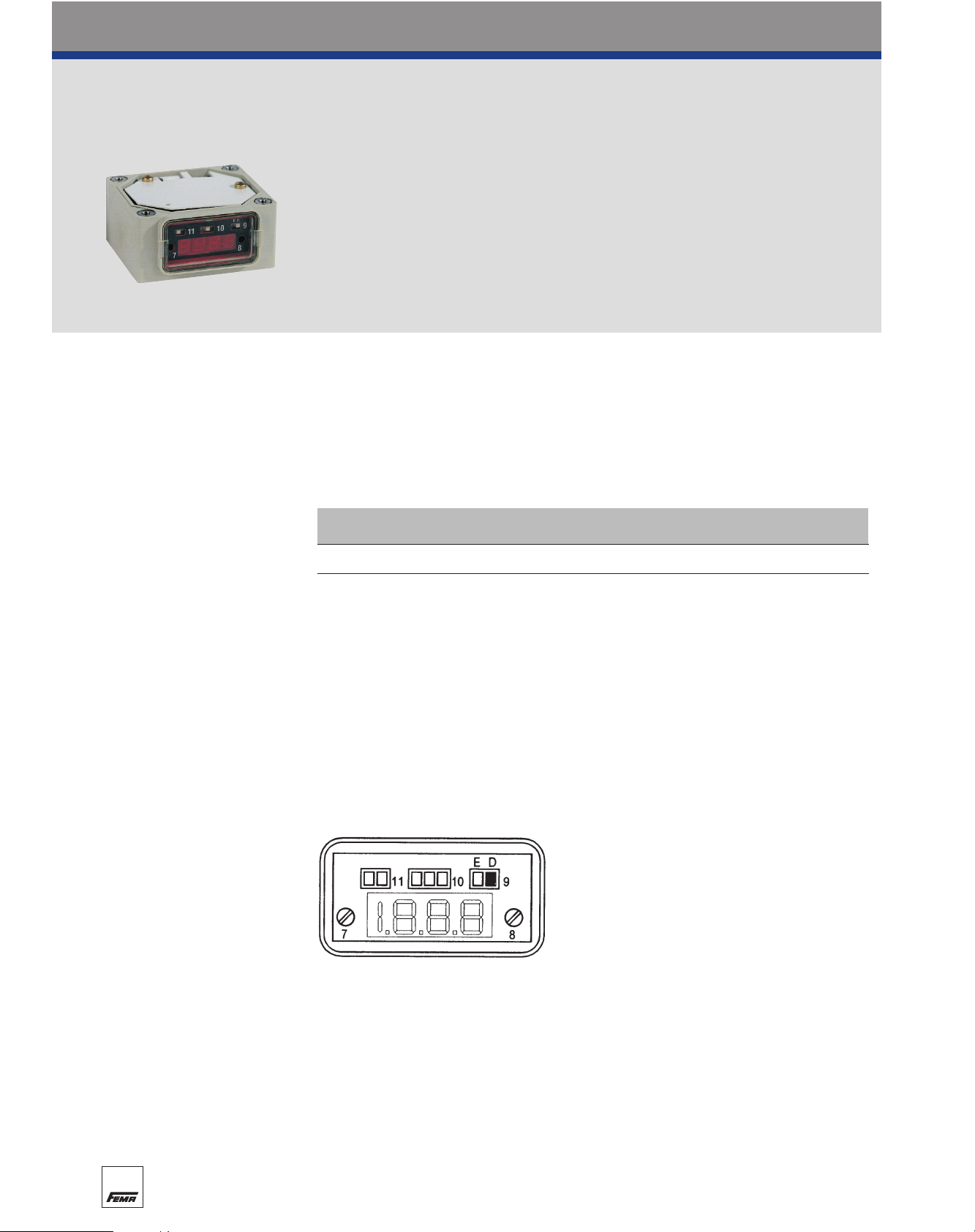
Controls
Potentiometer 7 For setting lower display value (e.g. for y-signal 0%)
Potentiometer 8 For setting upper display value (e.g. for y-signal 100%)
Input selector switch 9 Position D: Output signal of the evaluation module is displayed
(normal setting)
Position E: Signal of another module is displayed
Decimal point switch 10 For setting the decimal point
Decimal point switch 11 Decimal point on/off
Operator interface
AZ 331 (3 1/2 digit)
See above for description of
controls.
80
 Loading...