

Page 1
S6065A2001
S6065A1003/2001
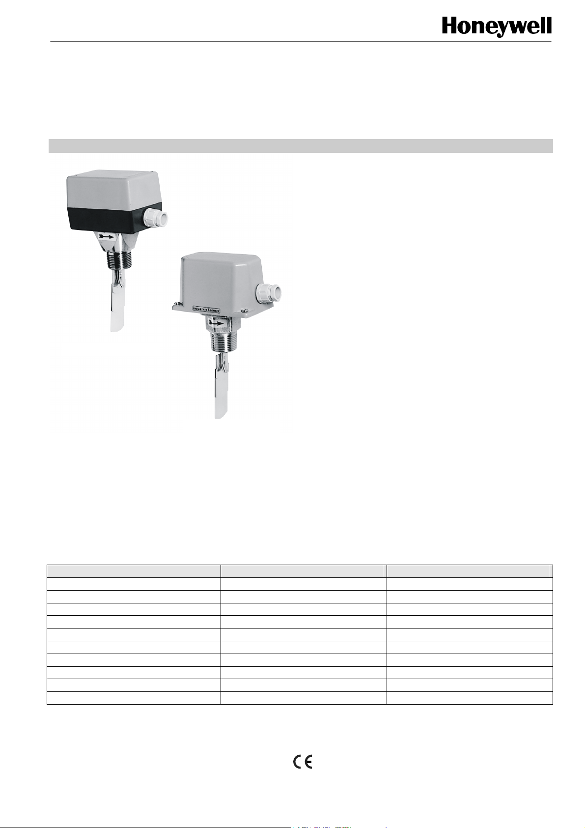
LIQUID FLOW SWITCHES
SPECIFICATION DATA & MOUNTING INSTRUCTIONS
FEATURES
• Cost-effective flow switches for HVAC applications.
• High-capacity, fully-encapsulated NC/NO micro-switch.
• A single type suitable for pipes with a diameter of 1 to 8".
COMMON SPECIFICATIONS
Switching capacity 15 (8) A, 24...250 Vac
Lifetime 50000 cycles at nominal load
Working temperature -40...+85 °C at 90% rel. humidity,
non-condensing
Electrical connection Screw terminal, wire up to 1.5 mm
cable ∅ 6...9 mm
Protection class I according to EN60730
Protection standard IP65 according to EN60529
Housing material ABS and corrosion-protected steel
Accessories PA2 Paddle set
2
MOUNTING
The S6065A1003 and S6065A2001 Liquid Flow Switches can
be mounted in any desired position far from elbows, valves,
and filters.
S6065A1003
GENERAL
The S6065A1003 and S6065A2001 Liquid Flow Switches are
designed for monitoring flow rates in pipes employed in HVAC
applications. They are suitable for monitoring flow in water,
oil, cooling circuits, and lubrication systems. The S6065A2001
is designed for monitoring aggressive liquids.
See Table 1 for the reset and switch points for water. Data for
other media must be determined empirically.
NOTE: The arrow on the housing must point downstream.
In the case of vertical pipes, reset the range to balance the
paddle weight. To prevent malfunction caused by impurities in
the medium, do not mount the device with the housing
pointing downwards.
When using multiple paddles, the paddles must be
arranged in order of decreasing length downstream,
i.e. with the longest paddle facing the oncoming
liquid.
MODELS
Specification S6065A1003 S6065A2001
Flow medium non-aggressive liquid aggressive liquid
Mounting Rp 1" (ISO7/1) Rp 1" (ISO7/1)
Maximum pipe temperature 120 °C 120 °C
Pressure 11 bar 30 bar
Paddle material 1.4401 1.4401
Lever yellow brass 1.4404
Sensor body yellow brass 1.4404
Housing dimensions 113 x 70 x 65 mm 108 x 70 x 72 mm
Weight 850 g 850 g
Approvals TÜV-approved TÜV-approved
® U.S. Registered Trademark EN0B-0314GE51 R01008
Copyright © 2008 Honeywell Inc. • All rights reserved
Page 2
S6065A1003/2001 LIQUID FLOW SWITCHES
SWITCH-POINT ADJUSTMENT
The flow switch is factory-set to the min. flow rate. To adjust
the device to other levels, turn the adjustment screw
clockwise. Table 1 lists the reset points and switch points for
water. Data for other media must be determined empirically.
Table 1. Reset and switch points for water
paddles (L) pipe Ø
1" 1" 3.6 0.6 / 1.0 2.0 / 2.1
1" 1-1/4" 6.0 0.8 / 1.3 2.8 / 3.0
1" 1-1/2" 9.0 1.1 / 1.7 3.7 / 4.0
1"+2" 2" 15.0 2.2 / 3.1 5.7 / 6.1
1"+2" 2-1/2" 24.0 2.7 / 4.0 6.5 / 7.0
1"+2"+3" 3" 36.0 4.3 / 6.2 10.7 / 11.4
1"+2"+3" 4" 60.0 11.4 / 14.7 27.7 / 29.0
1"+2"+3"+Z* 4" Z 60.0 6.1 / 8.0 17.3 / 18.4
1"+2"+3" 5" 94.0 22.9 / 28.4 53.3 / 55.6
1"+2"+3"+Z* 5" Z 94.0 9.3 / 12.9 25.2 / 26.8
1"+2"+3" 6" 120.0 35.9 / 43.1 81.7 / 85.1
1"+2"+3"+Z* 6" Z 120.0 12.3 / 16.8 30.6 / 32.7
1"+2"+3 8" 240.0 72.6 / 85.1
1"+2"+3"+Z* 8" Z 240.0 38.6 / 46.5 90.8 / 94.2
*For models with the suffix “Z,” the longest paddle must be used to
obtain the values indicated in this table. The Z = 8” paddle must be
cut to the proper length to fit into the pipe without touching the
inside.
rec. Q
(m3/h)
reset / switch point
max
min. flow
(m3/h)
max. flow
(m3/h)
165.7 / 172.5
NOTE: If the flow switch is used as a min. flow controller,
another device must be installed downstream for
alarm condition activation.
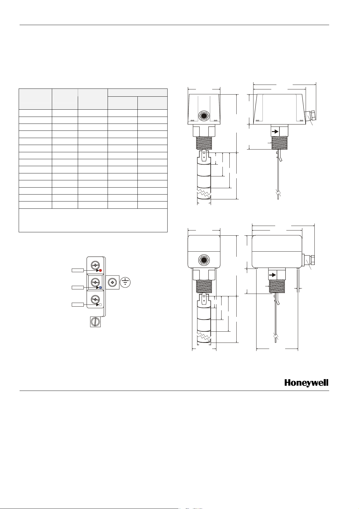
DIMENSIONS
R1”
135 mm
113 mm
135 mm
113 mm
PG11
70 mm
65 mm
126 mmL
54 mm
1”
2”
3”
29 mm
Fig. 2. S6065A1003 dimensions
70 mm
FIELD WIRING
72 mm
COMMON
RED
NORMALLY OPEN
NORMALLY CLOSED
BLUE
WHITE
ADJUSTMENT SCREW
FOR FLOW RATE
1”
132 mm
54 mm
R1”
2”
3”
L
Fig. 1. Field wiring
Connect the red and the white contacts. The contact redwhite opens when the flow drops below the switch point.
When the flow is absent, the contact red-blue closes and can
be used as a signal or alarm contact.
Manufactured for and on behalf of the Environmental and Combustion Controls Division of Honeywell Technologies Sàrl, Rolle, Z.A. La Pièce 16, Switzerland by its Authorized Representative:
Automation and Control Solutions
Honeywell GmbH
Böblinger Strasse 17
71101 Schönaich
Germany
Phone: (49) 7031 63701
Fax: (49) 7031 637493
http://ecc.emea.honeywell.com
Subject to change without notice. Printed in Germany
EN0B-0314GE51 R1008
29 mm
52 mm
Fig. 3. S6065A2001 dimensions
90 mm
PG11
diameter
4.5 mm
 Loading...