

Page 1
SmartLine Wireless Temperature and Universal IO Transmitters
34-SW-25-02, Revision 1, December 2019
INSTALLATION
Evaluate the site selected for the Transmitter installation with respect to the
process system design specifications and Honeywell’s published
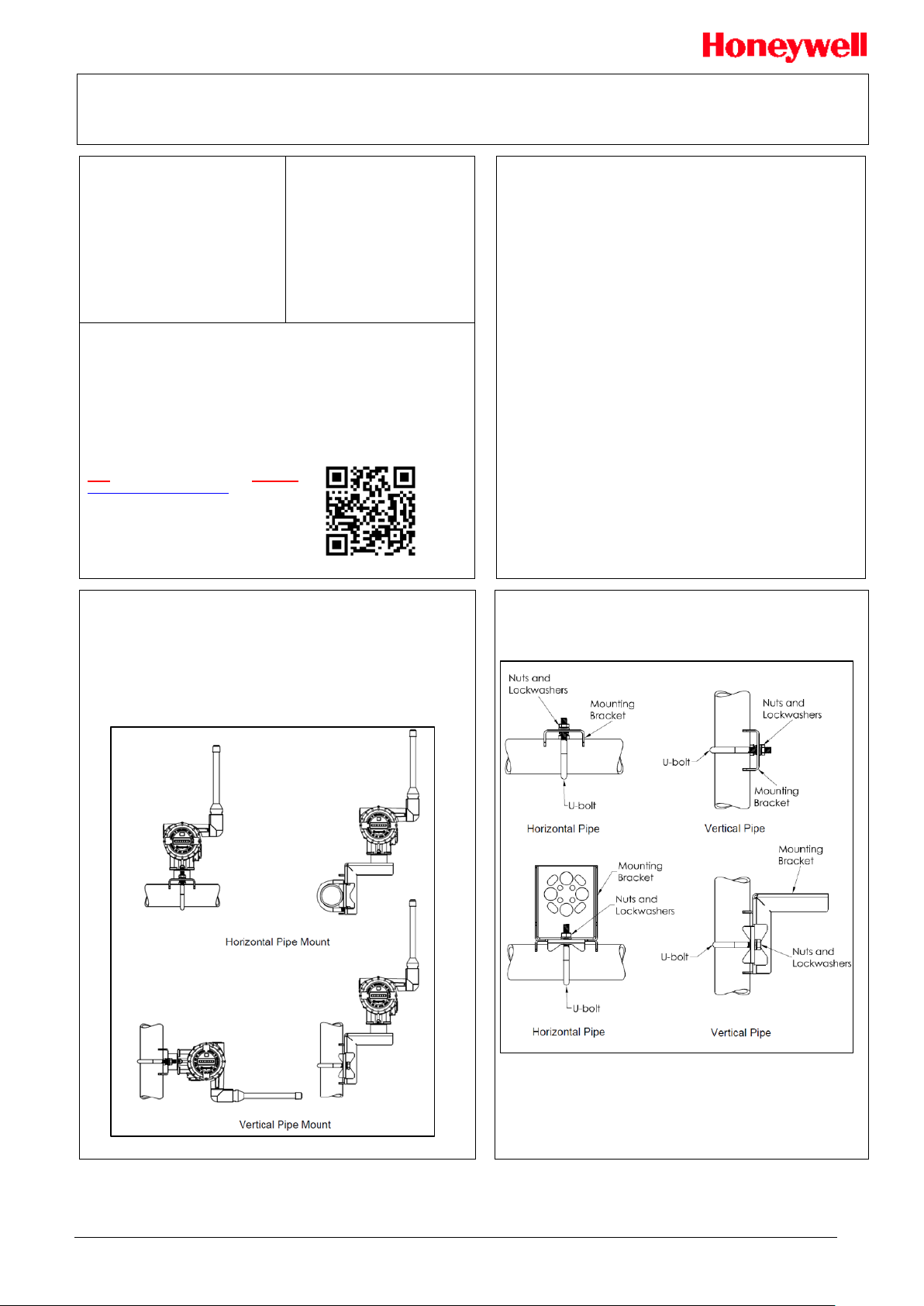
Figure 2: Mounting Brackets
Quick Start Installation Guide
For full details refer to the Wireless
Pressure User’s manual 34-SW-25-01
or the Wireless Temperature User’s
manual 34-SW-25-04, scan QR code
or use URL link below.
Including: Network, Security, Licensing,
Installation, Start Up, Operation,
Maintenance/Repair, Protocols and
Approvals/Certifications etc. including
options.
Documentation
To access complete documentation, including language variants, scan
the QR code below using your smart phone/device or QR code scanner.
Go to the APP store for your free Smartphone QR scanner
Or you can follow the URL to access the online SmartLine HUB page.
The HUB page will contain direct links to open SmartLine product
documentation.
URL QR Code
https://hwll.co/SmartLineHUB
performance characteristics for your particular model.
Mounting the Transmitter
Temperature/UIO models can be attached to a two-inch (50 millimeter)
vertical or hori zo ntal pipe using Hon e yw ell ’s o pt io nal angle or fl at m o unti ng
bracket; alternately you can use your own bracket.
Copyright
Copyright 2019 by Honeywell
Revision 1 – December 2019
Trademarks
SmartLine, is a U.S. registered
trademark of Honeywell Inc.
Table of Contents
Documentation ............................................................................................................. 1
URL ............................................................................................................................. 1
INSTALLATION ........................................................................................................... 1
Bracket Mounting .................................................................................................. 1
Mounting the Transmitter ...................................................................................... 1
Rotating Transmitter Housing ............................................................................... 2
Conduit Entry Plugs and Adapters ............................................................................... 2
Procedures ........................................................................................................... 2
Battery Power Option ................................................................................................... 2
Install/Replace batteries ....................................................................................... 2
24V Power Supply Option ............................................................................................ 3
ELECTRICAL CONNECTION SPECIFICATIONS ................................................ 3
STIW400 TEMPERATURE TRANSMITTER CONNECTIONS .................................... 3
STUW750 UNIVERSAL IO TRANSMITTER CONNECTIONS .................................... 3
STUW751 UNIVERSAL IO TRANSMITTER CONNECTIONS .................................... 3
Environmental Conditions ............................................................................................ 4
Maintenance ................................................................................................................ 4
General Operation ....................................................................................................... 4
EU Declaration of Conformity ...................................................................................... 4
EMC Conformity .......................................................................................................... 4
Hazardous Locations Certifications ............................................................................. 4
Conditions of Certification ............................................................................................ 5
FM Approval Specific Conditions of Use............................................................... 5
CSA, IECEx and ATEX Conditions of Certification ............................................... 5
Apparatus Marked with Multiple Types of Protection ............................................ 5
Radio Compliance Information..................................................................................... 5
Radio Frequency (RF) statement ......................................................................... 5
European Union restriction ................................................................................... 6
FCC compliance statements ................................................................................. 6
IC compliance statements .................................................................................... 6
Bracket Mounting
• Optional mounting bracket, see
• Rotating the transimitter housing, see Figure 3.
Figure 1: Flat and Angle Mounting Brackets
SmartLine Wireless Transmitter Quick Start Installation Guide 1
Page 2
Step
Action
1
Remove the protective plastic cap from the threaded
conduit entry.
2
To ensure the environment ingress protection rating on
may be used.
3
Thread the appropriate size conduit plug (M20 or ½’’
reducers will be used.
4
Tighten adapters according to the following table.
Description
Tool
Torque
M20 Conduit Entry
10mm Hex Wrench
32Nm
24Lb-ft
½’’ NPT Conduit Entry
10mm Hex Wrench
32Nm
24Lb-ft
Step
Action
1
Remove the protective plastic cap from the threaded conduit entry.
2
To ensure the environment ingress protection rating on tapered
threads (NPT), a non-hardening thread sealant may be used.
3
Thread the appropriate size adapter (M20 or ½’’ NPT) into the
conduit entry opening.
4
Tighten adapters according to the following table.
Description
Tool
Torque
½’’ to ¾’’ NPT Conduit Entry
¼’’ Wrench
32Nm
24Lb-ft
CONDUIT ENTRY PRECAUTIONARY NOTICE
THE CONDUIT/CABLE GLAND ENTRIES OF THIS PRODUCT ARE SUPPLIED
NVIRONMENT INTO WHICH THIS PRODUCT WILL BE
INSTALLED. THIS INCLUDES ENSURING COMPLIANCE WITH HAZARDOUS
GOVERNING AUTHORITIES AS APPLICABLE.
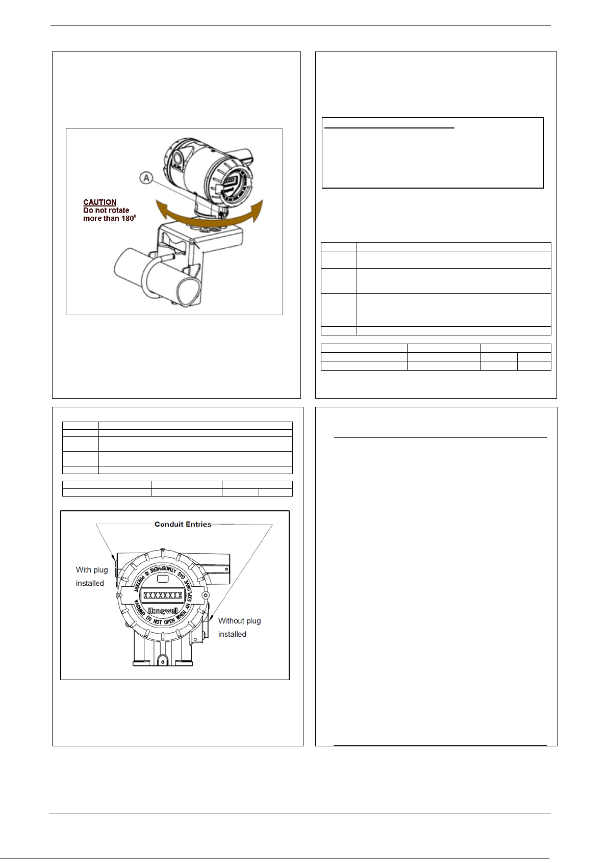
Rotating Transmitter Housing
You can rotate the transmitter for better viewing, access, or antenna
position. Loosen set screw (see A in Figure 3) on outside neck of
transmitter one full turn. Rotate transmitter housing up to 180 degrees in
either direction to desired position. Tighten set screw.
Figure 3: Rotating Transmitter Housing
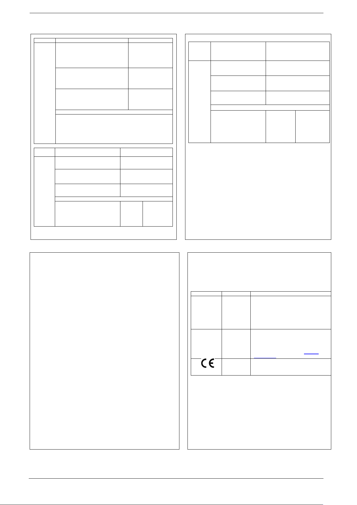
Conduit Entry Plugs and Adapters
Procedures
It is the User/Installer’s responsibility to install the Transmitters in
accordance with national and local code requirements. Conduit entry
plugs and adapters shall be suitable for the environment, shall be
WITH PLASTIC DUST CAPS WHICH ARE NOT TO BE USED IN SERVICE. IT
IS THE USER’S RESPONSI BILITY TO REPLACE THE DUST CAPS WITH
CABLE GLANDS, ADAPTORS AND/OR BLANKING PLUGS WHICH ARE
SUITABLE FOR THE E
LOCATION REQUIREMENTS AND REQUIREMENTS OF OTHER
certified for the hazardous location when required and acceptable to the
authority having jurisdiction for the plant.
Use the following procedures for installation:
Table 1 – Conduit Entry Plugs
tapered threads (NPT), a non-hardening thread sealant
NPT) into the conduit entry opening. Do not install conduit
entry plugs in conduit entry openings if adapters or
Table 1 – Conduit Adapters
Battery Power Option
Install/Replace batteries
WARNING
Risk of death or serious injury from explosion or fire.
• When not in use the Battery Pack must be stored in a non
Note. NO plugs come installed in the housing. All housings come with
temporary plastic dus t pr otecto rs (red ) install ed and a re not c ertifi ed fo r use
in any installation.
Figure 4: Electronic Housing Conduit Entries
Hazardous Area
• Do not change batteries in an explosive gas atmosphere.
• The batteries used in this device may present a risk of fire or
chemical burn if mistreated. Do not recharge, disassemble, heat
above 100°C (212°F), or incinerate.
• When installing batteries, do not snag the battery terminal on
the clip or the battery may be damaged. Do not apply excessive
force.
• Do not drop. Dropping the battery may cause damage. If a
battery is dropped, do not install the dropped battery into the
transmitter. Dispose of dropped battery promptly per local
regulations or per the battery manufacturer’s recommendations.
ATTENTION
Both batteries must be the same model from the same
manufacturer. Mixing old and new batteries or different
manufacturers is not permitted.
Use only the following 3.6V lithium thionyl chloride (Li-SOCl2)
batteries (non-rechargeable), size D. No other batteries are
approved for use in SmartLine Wireless Transmitters.
• Xeno Energy XL-205F
• Eagle Picher PT-2300H
• Tadiran TL-5930/s
• Tadiran GmbH, SL-2780 (Not approved by FM or CSA)
• Honeywell p/n 50026010-501 (Two 3.6V lithium thionyl
chloride batteries)
• Honeywell p/n 50026010-502 (Four 3.6V lithium thionyl
chloride batteries)
• Honeywell p/n 50026010-503 (Ten 3.6V lithium thionyl
chloride batteries)
SmartLine Wireless Transmitter Quick Start Installation Guide 2
Page 3

+
-
STW TRANSMITTER WITH 24VDC POWER SUPPLY OPTION
(Antenna and Meterbody Omitted for Clarity)
GROUND SHIELD AT THIS END ONLY
+
-
THE POWER SUPPLY OUTPUT SHALL
ONLY BE CONNECTED TO THE
INTERNAL TRANSMITTER CABLE
24Vdc Supply
16.0 Vmin
28.0 Vmax
100 mA max
T/C or mV or DI or 2 Wire Resistance
1
2
3
4
5
6
TB1
TB2
PV1
PV2
PV3
PV4
+
+
+
+
-
-
-
-
3 Wire RTD or Resistance
1
2
3
4
5
6
TB1
TB2
PV1
PV3
3 Wire RTD or Resistance
1
2
3
4
5
6
TB1 TB2
PV1
PV3
PV4
+
+
-
-
T/C or mV or DI or 2 Wire Resistance
HLAI (0/4-20mA) or T/C or mV or DI or 2 Wire Resistance
1
2
3
4
5
6
TB1 TB2
PV1 PV2
+
+
-
-
+
-
+
-
+
-
+
-
PV3
HLAI (0/4-20mA) or T/C or mV o r DI or 2 Wir e Resistance
AND Dig ital Output
1
2
3
4
5
6
TB1
TB2
PV1
PV2
+
+
-
-
+
-
+
-
+
-
PV3 Dig ital
Outpu t
24V Power Supply Option
ELECTRICAL CONNECTION SPECIFICATIONS
The 24V power supply requires 16 Vdc to 28 Vdc, 100 mA max supply connection
to the 24V wirin g connector te rminals. Fo r hazardous location instal lation, and
intrinsic safety entity parameters, refer to the control drawing.
1. The 24V wiring terminals will accept 26 to 12-gauge wiring. The
terminals shall be torqued from 0.4 Nm to 0.5 Nm (3.5 to 4.4 lb-in).
(Ordinary Non-Ha zar do us Locations)
STIW400 TEMPERATURE TRANSMI TTER CONNE CTI ONS
Figure 5: Power Supply 24Vdc Option (DC) System Diagram
STUW750 UNIVERSAL IO TRANSMITTER CONNECTIONS
NOTES:
Figure 7: STUW750 Universal Io Transmitter Connections
1. The terminals accept 14-26AWG wire, and the screws shall be torqued to
0.4-0.5Nm (3.5 – 4.4 in-lb)
2. Any combination of sensor type inputs is allowed
3. Shielded cable is required for EMC conformity and is recommended for
all remote sensor installations. The shield shall be grounded at the
transmitter end only. If the shiel d is gro unded at the remote end, the
shield shall not be connected at the transmitter end.
4. When remote mounted probe sensors are used, and the shield is
grounded at the probe, the shield shall not be connected at the
transmitter end.
5. Duplex (redundant) sensors that are bonded to the probe are not
permitted. All thermocouple/mV and RTD/ohms inputs must be insulated
from ground (the probe) and from each other.
6. Digital Input switches, DI, must be dry contact type, simple apparatus
and properly segregat ed from all oth er sour ces of po wer.
SmartLine Wireless Transmitter Quick Start Installation Guide 3
Figure 6: STIW400 Temperature Transmitter Connections
NOTES:
1. The terminals accept 14-26AWG wire, and the screws shal l be
torqued to 0.4-0.5Nm (3.5 – 4.4 in-lb)
2. Any combination of sensor type inputs is allowed
3. Shielded cable is required for EMC conformity and is
recommended for all remote sensor installations. The shield shall
be grounded at the transmitter end only.
4. When remote mounted probe sensors are used and the shield is
grounded at the probe, the shield shall not be connected at the
transmitter end.
5. Duplex (redundant) sensors that are bonded to the probe are not
permitted. All thermocouple/mV and RTD/ohms inputs must be
insulated from ground (the probe) and from each other.
6. Digital Input switches, DI, must be dry contact type, simple
apparatus and properly segregated from all other sources of
power.
STUW751 UNIVERSAL IO TRANSMITTER CONNECTIONS
Figure 8: STUW751 Universal Io Transmitter Connections
NOTES:
1. The terminals accept 14-26AWG wire, and the screws shal l be
torqued to 0.4-0.5Nm (3.5 – 4.4 in-lb)
2. Any combination of sensor type inputs is allowed
3. Shielded cable is required for EMC conformity and is
recommended for all remote sensor installations. The shield shall
be grounded at the transmitter end only. If the shield is grounded at
the remote end, the shield shall not be connected at the transmitter
end.
4. When remote mounted probe sensors are used and the shield is
grounded at the probe, the shield shall not be connected at the
transmitter end.
5. Duplex (redundant) sensors that are bonded to the probe are not
permitted. All thermocouple/mV and RTD/ohms inputs must be
insulated from ground (the probe) and from each other.
6. Digital Input switches, DI, must be dry contact type, simple
apparatus and properly segregated from all other sources of
power.
Page 4

DIRECTIVE
DESCRIPTION
2014/53/EU
Radio Equipment Directive
2014/34/EU
ATEX Directive
2014/68/EU
Pressure Equipment Directive (for
pressure models)
STANDARD
DESCRIPTION
EN 300 328 V2.1.1
Wideband transmission systems;
2,4GHz ISM band
EN 61326-1: 2013
Electrical equipment for
use - EMC requirements
EN 301 489-1 V2.1.1
ElectroMagnetic Compatibility (EMC)
services
AGENCY
TYPE OF PROTECT ION
Ambient Temperature
Intrinsically Safe:
Ex ic IIC T4 Gc
Non Incendive:
Gc
Explosion-Proof/ Flam e pr oo f/D u st Pr oof :
Class II, Zn 21, AEx tb [ia Da] IIIC T95 Db
Enclosure: Type 4X/ IP66/ IP67
Standards Used:
CSA C22.2 No. 0
CAN/CS
ANSI/UL 60079
FM 3616
CAN/CSA C22.2 No.60529:16
ANSI/ISA 12.12.01
FM 3600
ANSI/UL 61010
CAN/CSA C22.2 No.60079
ANSI/UL 60079
FM 3615 – Aug 2006, ANSI/UL 913-2015
Environmental Conditions
Refer to the specification sheet for performance considerations.
The transmitter operates with an ambient temperature of -40
o
C to +85 oC. If
installed in a hazardous environment, the maximum ambient temperature may
be limited. Refer to the control drawing and the markings on the transmitter
nameplate.
Ambient humidity limits are 0 to 100% relative humidity.
The transmitter may be installed indoors or outdoors, with pollution degree 4.
The enclosure is rated Type 4X, IP66 / IP 67.
The transmitter operates up to an altitude of 2,000 m.
Entry plugs/glands rated for the installation environment are required to be
installed on the transmitter.
Maintenance
The SmartLine Wireless Transmitter itself does not require any specific
maintenance routine at regularly scheduled intervals, other than changing the
batteries as required.
If the transmitter requires repair or replacement parts, please contact your local
Honeywell TAC. TAC contact information can be found on the last sheet of this
quick start guide.
General Operation
1. INSTALL.
2. ANTENNA. The transmitter can be supplied with an integral 4dBi
antenna. If the transmitter is equipped with a remote mount
antenna connection, connect the antenna with a RF cable. The
transmitter remote mount and antennas utilize N-type connectors.
3. POWER up the transmitter.
Remove the end cap, opposite the LCD display, to connect
power. Ensure the internal power cable is connected to the
battery pack or 24V supply module as applicable.
Once powered, verify that the transmitter LCD is functioning. If
the LCD is blank , check the power connections, and batteries as
applicable.
4. PROVISION the transmitter to the network
a. Over The Air (OTA) provisioning can be done using the
Wireless Device Manager (WDM) interface.
b. Handheld provisioning can be done through the IR port with a
Handheld Provisioning Device such as MCT404
5. VERIFY that the transmitter connects in the wireless network, and
can transmit PVs. This step may take several minutes,
depending on your network.
a. Load the DD file (if not done previously)
b. Configure the transmitter as desired using the property panel
c. Configure the channel(s) as desired using the pr op ert y p anel .
d. Activate the channel(s)
6. CALIBRATE. If required, calibration should only be done after the
transmitter is installed in its final location.
EU Declaration of Conformity
A copy of the Smartline Wireless Transmitters EU Declaration of Conformity can be
downloaded here:
https://www.honeywellprocess.com/library/support/Public/Documents/50136122.pdf
The Smartline Wireless Transmitters complies with the following directives
EMC Conformity
The Smartline Wireless Transmitters complied with the following EMC standards
SmartLine Wireless Transmitter Quick Start Installation Guide 4
Hazardous Locations Certifications
Hazardous location certifications
Refer to product label for applicable approvals and control drawing.
Table B-2 Certifications and Approvals
Class I; Division 1; Groups A, B, C, D;
Class II, Division 1, Groups E, F, G;
Class III, Division 1; T4
Class I, Zone 0 AEx ia IIC T4 Ga
Class I Zone 2 AEx ic IIC T4 Gc
Ex ia IIC T4 Ga
Class I; Division 2; Groups A, B, C, D;
Class II, Division 2, Groups E, F, G;
Class III, Division 2, T6...T5
Ex nA [ia Ga] IIC T6...T5 Gc
Class I, Zn 2, AEx nA [ia Ga] IIC T6...T5
Class I, Division 1; Groups A, B, C, D;
Class II, Division 1, Groups E, F, G;
Class III, Division 1; T6...T5
Ex db [ia Ga] IIC T6...T5 Gb
Ex tb [ia Da] IIIC T95 Db
Class I, Zn 1 AEx db [ia Ga] IIC T6...T5 Gb
-10, CSA C22.2 No.94.2-15, CSA C22.2 No.213-16,
A C22.2 No.60079-1:16, CAN/CSA C22.2 No.60079-31:15
-1-2015, ANSI/UL 60079-31-2015
– Dec 2011, ANSI/UL 50E-2015
CSA C22.2 No.25-17, CAN/CSA C22.2 No.61010-1-12
-2015, ANSI/UL 60079-11-2014
– Dec 2011, ANSI/IEC 60529 – 2004
CSA C22.2 No.30-M1986, CAN/CSA C22.2 No.157-92
-1-2016
-0-2013, ANSI/UL 60079-15-2013
, CAN/CSA C22.2 No.60079-11:14
-0:15, CAN/CSA C22.2 No.60079-15:16
-40 to +80°C: ia
-40 to +85°C: ic
-40°C to +85°C : T5
-40°C to +75°C : T6
-40°C to +85°C : T5
-40°C to +75°C : T6
-40°C to +85°C : T95
Data transmission equipment
operating in the
measurement, control and laboratory
standard for radio equipment and
CSA
(USA and
Canada)
Page 5
AGENCY
TYPE OF PROTECT ION
Ambient Temperature
Approvals
Intrinsically Safe:
T4
Non Incendive:
T5...T6
Dust Proof:
Db
C : T5, T95
Enclosure: Type 4X/ IP66/ IP67
Standards Used:
ANSI/ ISA 60079-11: 2014, ANSI/ ISA 60529: 2004
AGENCY
TYPE OF PROTECT ION
Ambient Temperature
Intrinsically Safe:
II 3 G Ex ic IIC T4 Gc
-40 to +80°C: ia
Flameproof / Dust Proof:
-40°C to +85°C : T5
Non Incendive:
-40°C to +85°C : T5
Enclosure: IP66/ IP67
Standards Used:
EN 60079
2014
EN 60079
2015
AGENCY
TYPE OF PROTECT ION
Ambient Temperature
Intrinsically Safe:
-40 to +80°C: ia
Flameproof / Dust Proof:
Ex tb [ia Da] IIIC Db T95C
-40°C to +85°C : T5
Enclosure: IP66 /IP67
Standards Used:
Agency
Certification
Description
Communications
The SmartLine Wireless Transmitters comply
cause undesired operation.
Industry Canada
The installer of this radio equipment must
sc.gc.ca/rpb.
The SmarLine wireless transmitter has been
2014/53/EU.
IS Class I, II, III; Division 1; Groups
ABCDEFG; T4
Class I, Zone 0 AEx ia IIC Ga T4
Class I, Zone 2[0] AEx ic [ia Ga] IIC Gc
NI-AIS Class I; DIV 2; Groups ABCD;
T5...T6
Class I, Zone 2[0] AEx nA [ia Ga] IIC Gc;
FM
TM
(USA)
DIP-AIS Class II, III DIV 1; Groups EFG;
T5...T6
Zone 21[20] AEx tb [ia Da] IIIC T95°C
FM 3600:2018, ANSI/ISA 60079-0: 2013
ANSI/ ISA 60079-15: 2013, ANSI/ NEMA 250: 2008
FM 3610: 2018, FM 3810: 2018
ANSI/ ISA 60079-31: 2015
FM 3611: 2018, FM 3616: 2011
II 1 G Ex ia IIC T4 Ga
II 2[1] G Ex d [ia Ga] IIC T6...T5 Gb
II 2[1] D Ex tb [ia Da] IIIC 95C Db
II 3[1] G Ex ec [ia Ga] IIC T6...T5 Gc
ATEX
EN 60079-0 : 2012 + A1:2013
-40 oC to +85 °C
-40 °C to +85 °C : T5
-40 °C to +70 °C : T6
-40 °C to +85 °
-40 °C to +70 °C : T6
-40 to +85°C: ic
-40°C to +75°C : T6
-40°C to +75°C : T6
-1 :
EN 60079-11 :
2012
-7 :
IEC 60079-31
2013
Conditions of Certification
FM Approval Spe ci f ic C o nd itions of Use
1) For Zone 2 installation with the 24V Power Supply, the installer shall
provide transient over-voltage protection external to the equipment
such that the voltage at the supply terminal of the equipment does not
exceed 140% of the voltage rating of the equipment.
2) The enclosure contains aluminum and is considered to present a
potential risk of ignition by impact or friction. Care must be considered
during installation and use to prevent impact or friction.
3) Painted surface of the enclosure may store electrostatic charge and
become a source of ignition in applications with a low relative humidity
less than approximately 30% relative humidity where the painted
surface is relatively free of surface contamination such as dirt, dust or
oil. Cleaning of the painted surface should only be done with a damp
cloth.
CSA, IECEx and ATE X Conditions of Certification
1) Under certain extreme circumstances, the non-metallic parts
incorporated in the enclosure of this equipment may generate an
ignition-capable level of electrostatic charge. Therefore, the
equipment shall not be installed in a location where the external
conditions are conducive to the build-up of electrostatic charge on
such surfaces. In addition, the equipment shall only be cleaned with
a damp cloth.
2) The enclosure is manufactured from low copper aluminum alloy. In
rare cases, ignition sources due to impact and friction sparks could
occur. This shall be considered during installation, particularly if the
equipment is installed in a zone 0 location.
Apparatus Marked with Multiple Types of Protection
The user must determine the type of protection required for installation of the equipment.
The user shall then check the box [�] adjacent to the type of protection used on the
equipment certification nameplate. Once a type of protection has been checked on the
nameplate, the equipment will not be reinstalled using any of the other certification types.
Ex ia IIC T4 Ga
Ex ic IIC T4 Gc
Ex db [ia Ga] IIC T6...T5 Gb
Non Incendive:
IECEx
Radio Compliance Information
The SmartLine Wireless pressure transmitter uses a low powered ISA100 2.4GHz
radio to communicate with the Radio Infrastructure and Gateway devices that are
connected to a wired DCS network. The wireless transmit power is set at the factory
depending on the destination country. The combination of allowed transmit power and
antenna gains result in a maximum EIRP of 26 dBm = 398 mW transmitted power.
This power is limited depending on destination country.
Federal
Commission
(FCC)
(IC)
Ex ec [ia] IIC T6..T5
IEC 60079-0 : 2017
Table B4: Radio Certifications
FCC ID:
S5751454941
IC:
573WI51454941
-40 to +85°C: ic
-40°C to +85°C : T5
-40°C to +75°C : T6
-40°C to +75°C : T6
IEC 60079-1
: 2014
IEC 60079-7
: 2015
with part 15 of the FCC rules. Operation is
subject to the following two conditions.
(1) this device may not cause harmful
interference, and
(2) this device must accept any interference
received, including interference that may
ensure that the antenna is located or pointed
such that it does not emit RF fields in excess
of Health Canada limits for the general
population; consult Safety Code 6, obtainable
from Health Canada’s web site www.hc-
assessed and is in compliance with the
Radio Equipment Directive (RED)
IEC 60079-11 :
2011
IEC 60079-31 :
2013
Radio Frequency (RF) st at em ent
To comply with FCC’s and Industry Canada’s RF exposure requirements, the
following antenna installation and device operating configurations must be satisfied.
• Remote Point-to-Multi-Point antenna(s) for this unit must be fixed and mounted
on outdoor permanent structures with a separation distance between the
antenna(s) of greater than 20cm and a separation distance of at least 20cm
from all persons.
• Remote Fixed Point–to-Point antenna(s) for this unit must be fixed and
mounted on outdoor permanent structures with a separation distance between
the antenna(s) of greater than 20cm and a separation distance of at least
100cm from all persons.
• Furthermore, when using integral antenna(s) the SmartLine Wireless
Transmitter unit must not be co-located with any other antenna or transmitter
device and have a separation distance of at least 20cm from all persons.
SmartLine Wireless Transmitter Quick Start Installation Guide 5
Page 6

34-SW-25-02, Rev.1
2019 Honeywell International Inc.
ATTENTION
ASIA PACIFIC (TAC) hfs-tac-support@honeywell.com
EMEA, Phone: + 80012026455 or +44 (0)1202645583. FAX: +44 (0) 1344 655554
AMERICAS, Honeywell Process Solutions,
European Union restriction
The SmartLine Wireless Transmitters are in conformity with the applicable standards
as required by the Radio Equipment Directive (RED) 2014/53/EU.
SmartLine Wireless units must be professionally installed
FCC compliance statem en ts
• This device complies with Part 15 of FCC Rules and Regulations. Operation is
subject to the following two conditions: (1) This device may not cause harmful
interference and (2) this device must accept any interference received,
including interference that may cause undesired operation.
• This equipment has been tested and found to comply with the limits for a Class
A digital device, pursuant to Part 15 of the FCC Rules. These limits are
designed to provide reasonable protection against harmful interference in a
residential installation. This equipment generates, uses, and can radiate
radiofrequency energy and, if not installed and used in accordance with these
instructions, may cause harmful interference to radio communications.
Operation of this equipment in a residential area is likely to cause harmful
interference in which case the user will be required to correct the interference
at own expense.
• Intentional or unintentional changes or modifications must not be made to the
SmartLine Wireless Transmitters unless under the express consent of the
party responsible for compliance. Any such modifications could void the user’s
authority to operate the equipment and will void the manufacturer’s warranty.
IC compliance statements
• To reduce potential radio interference to other users, the antenna type and its
gain should be so chosen that the equivalent isotropic radiated power (EIRP)
is not more than that permitted for successful communication.
• Operation is subject to the following two conditions: (1) this device may not
cause interference, and (2) this device must accept any interference, including
interference that may cause undesired operation of the device.
• This Class A digital apparatus complies with Canadian ICES-003.
French: Cet appareil numérique de la classe A est conforme à la norme NMB-003 du
Canada.
WARRANTY/REMEDY
Honeywell warrants goods of its manufacture as being free of defective
materials and faulty workmanship. Contact your local sales office for
warranty information.
If warranted goods are retu rn ed to Hon e ywell du ring the period of
coverage, Honeywel l will rep air or re pla c e wit hou t char ge th os e item s it
finds defective. The foregoing is Buyer's sole remedy and is in lieu of all
other warranties, expr ess e d or implied, including those of
merchantability and fitness for a particular purpose. Specifications may
change without notice. The information we supply is believed to be
accurate and reliable as of this printing. However, we assume no
responsibility for its use .
While we provide application assistance personally, through our
literature and the Honeywell web site, it is up to the customer to
determine the suitability of the product in the application.
Sales and Service
For application assistance, current specifications, pricing, or
nearest Authorized Distributor, contact one of the offices below.
Australia Honeywell Limited, Phone: +(61) 7-3846 1255, FAX: +(61) 7-3840 6481
Toll Free 1300-36-39-36, Toll Free Fax: 1300-36-04-70
China – PRC – Shanghai, Honeywell China Inc. Phone: (86-21) 5257-4568,
Fax: (86-21) 6237-2826
Singapore, Honeywell Pte Ltd. Phone: +(65) 6580 3278. Fax: +(65) 6445-3033
South Korea, Honeywell Korea Co Ltd. Phone:+(822)799 6114. Fax:+(822) 792
9015
Email: (Sales) sc-cp-apps-salespa62@honeywell.com
or (TAC) hfs-tac-support@honeywell.com
Phone: (TAC) 1-800-423-9883 or 215/641-3610. (Sales) 1-800-343-0228.
Email: (Sales) FP-Sales-Apps@Honeywell.com
or (TAC) hfs-tac-support@honeywell.com
name of the
For more information
To learn more about SmartLine Transmitters,
visit www.honeywellprocess.com
Or contact your Honeywell Account Manager
Process Solutions
Honeywell
1250 W Sam Houston Pkwy S
Houston, TX 77042
Honeywell Control Systems Ltd
Honeywell House, Skimped Hill Lane
Bracknell, England, RG12 1EB
Shanghai City Centre, 100 Jungi Road
Shanghai, China 20061
www.honeywellprocess.com
December 2019
 Loading...