

Page 1
Put Bar Code Here
LONWORKS® Bus
TERMINATION
MODULE
TERMINATION
MODULE
DEVICE
DEVICE
DEVICE
TERMINATION
MODULE
TERMINATION
MODULE
DEVICE
DEVICE
DEVICE
MIXED
LOOP
DEVICE
DEVICE
DEVICE
DEVICE
DEVICE
DEVICE DEVICE
DEVICE
DEVICE
DEVICE
DEVICE DEVICE
DEVICE DEVICE
SINGLY TERMINATED
STAR
DEVICE DEVICE
DEVICE DEVICE
DEVICE
M12197
Wiring Guidelines
HONEYWELL CABLE 3252, 3253, 1061,
AK3797, AK3798, AK3799
INTRODUCTION
The Free Topology Transceiver (FTT) supports polarity
insensitive, free topology wiring. This frees the system
installer from wiring using a specific bus topology. T-tap, star,
loop, and mixed wiring topologies are all supported by this
architecture. Free topology wiring reduces the time and
expense of system installation by allowing the wiring to be
installed in the most expeditious manner. It also simplifies
network expansion by eliminating restrictions on wire routing,
splicing, and device placement.
USER’S GUIDE
A FTT network may comprise multiple segments (L
Bus sections containing from one to sixty devices, each
device having a Neuron® ID to validate) separated by
ONWORKS
physical layer repeaters or routers.
FTT networks are very flexible and convenient to install and
maintain, but it is imperative to carefully plan the network
layout and create and maintain accurate documentation. This
will aid in compliance verification and future expansion of the
FTT network. This will also minimize unknown or inaccurate
wire run lengths, node-to-node (device-to-device) distances,
node counts, total wire length, inaccurate repeater/router
locations, and misplaced or missing terminations.
APPLICATIONS
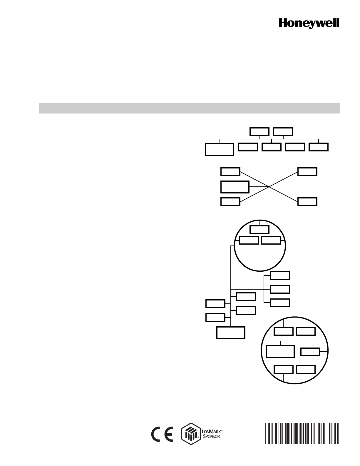
Free topology architecture allows the user to wire the control
devices with virtually no topology restrictions.
Unlike bus wiring designs, the FTT system uses a free
topology wiring scheme that supports T-tap, star, loop, mixed,
and/or daisy-chain (see Fig. 1). This design has many
advantages. First, the installer is free to select the method of
wiring that best suits the installation, reducing the need for
advanced planning and allowing last minute changes at the
installation site. Second, if installers have been trained to use
one style of wiring for all installations, free topology
technology can be introduced without requiring retraining.
Third, retrofit installations with existing wiring plans can be
accommodated with minimal, if any, rewiring. This capability
ensures that FTT technology can be adapted to both old and
new projects, widening the potential market for FTT based
products. Finally, free topology allows FTT systems easy
future expansion by tapping into the existing wiring where it is
most convenient to do so. This reduces the time and expense
of system expansion, and from the customers’ perspective,
keeps down the life cycle cost of the free topology network.
Fig. 1. Typical wiring topologies
supported by the FTT System.
74-2865—04
Page 2
LONWORKS® BUS WIRING GUIDELINES
209541B
TERMINATION
MODULE
209541B
TERMINATION
MODULE
209541B
TERMINATION
MODULE
Q7740A
REPEATER
Q7740A
REPEATER
Q7751A2002
ROUTER
DAISY-CHAIN
TOPOLOGY
DAISY-CHAIN
TOPOLOGY
DAISY-CHAIN
TOPOLOGY
DAISY-CHAIN
TOPOLOGY
209541B
TERMINATION
MODULE
M12369A
Q7740B
4-WAY
REPEATER
209541B
TERMINATION
MODULE
DAISY-CHAIN
TOPOLOGY
FREE
TOPOLOGY
FREE
TOPOLOGY
FREE
TOPOLOGY
M12368
Q7740A
2-WAY
REPEATER
FREE
TOPOLOGY
FREE
TOPOLOGY
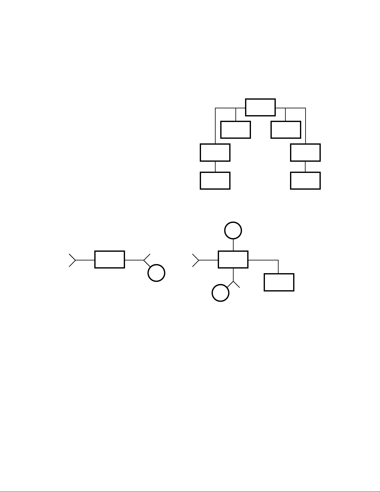
System expansion is simplified by the use of physical layer
repeaters and routers. The Q7740A 2-Way or Q7740B 4-Way
devices perform a repeater function, and the Q7751A
operates as a router. See Fig. 2. If a L
ONWORKS Bus segment
grows beyond the maximum number of devices or total wire
distance, additional FTT segments can be added. This is done
by connecting a Q7740A 2-Way or a Q7740B 4-Way physical
layer repeater (see Fig. 3). The repeaters will transfer data
between the two L
ONWORKS Bus segments, allowing the
number of devices to be spread out as well as increasing the
length of wire over which they c omm unicate.
NOTE: Do not exceed the maximum of 120 devices for a
Q7750A Zone Managers L
(up to 60 devices are allowed per L
ONWORKS Bus network
ONWORKS Bus
segment).
The repeater function permits an FTT network to grow as
system needs expand, without retrofitting existing controllers
or requiring the use of specialized bridges. The maximum
number of repeaters per L
(on either side of the router). A Q7751A L
ONWORKS Bus segment is one
ONWORKS Bus
router can also be used to effectively double the maximum
L
ONWORKS Bus length. The advantage of using the router is
that it will segregate traffic to a L
ONWORKS Bus segment.
When using the repeater all traffic is repeated on each
L
ONWORKS Bus segment. (see following NOTES).
NOTES:
— There can be no more than one repeater on either
side of a Q7751A router.
— An FTT network can have no more than one router
per Zone Manager. Systems requiring high levels
of network traffic may benefit from the use of a
Q7751A router , which forwards p ackets only when
necessary. Routers are not allowed within loops.
Fig. 2. Repeaters and router in a FTT network.
Fig. 3. Physical layer repeater (Q7740A 2-Way or Q7750B 4-Way).
NETWORK CABLING AND CONNECTIONS
This section provides information about cabling and FTT
network connections.
IMPORTANT
• For network terminal connections, twist the wires
together a minimum of three times.
• Only use approved wire and do not use different wire
types on the same bus.
• Follow the bus length limits for the cable type used.
• Properly install the 209541B FTT Termination
74-2865—04 2
Module, see Fig. 4 through 7.
System Performance and Cable Selection
Transmission Specifications
The free topology transmission specifications include two
rules that must both be met for proper system operation:
1. The distance from each device to all other devices and
to the termination must not exceed the (singly
terminated) maximum node-to-node (device-to-device)
distance. For example, if multiple paths exist using loop
topology, then use the longest path for the calculations.
2. The maximum total wire length is the total amount of
wire connected per L
NOTE: See Table 1 for daisy-chain doubly terminated FTT
network bus topology transmission specifications
and Echelon® cable parameters.
ONWORKS Bus segment.
Page 3

LONWORKS® BUS WIRING GUIDELINES
Table 1. Daisy-chain FTT Network Bus Topology Transmission Specifications (Doubly Terminated).
Wire/Cable Type (Unshielded)
Honeywell Cable 1125 (stranded non-plenum) 79 67
Belden 85102 (stranded non-plenum) 56 62
Cable Parameters
16/1.5 mm
16/1.5 mm
2
17.9 4600 feet (1400 m)
2
28 8900 feet (2700 m)
Maximum FTT Network Bus
Length for Segment(s)C nF/km Vprop% of c AWG/Dia. RloopW/km
Belden 8471 (stranded non-plenum) 72 55
Level IV Cable Specifications, 22AWG (solid/
stranded twisted pair)
TIA568A Category 5 24 AWG (twisted pair
solid or stranded, plenum or non-plenum)
49 67
46 58
22/.34 mm
24/.27 mm
2
106 4600 feet (1400 m)
2
168 3000 feet (900 m)
NOTES:
— See Table 2 for singly terminated FTT network bus topology transmission specifications.
— See Tables 3 and 4 for a list of Honeywell provided FTT daisy-chain and free topology network wire/cables.
— See the generic cable manufacturer information that meets Echelon LonWorks Bus specifications in Table 5.
Table 2. FTT Network Free Topology Transmission Specifications (Singly Terminated).
Maximum Length for Segment(s)
Wire/Cable type (Unshielded)
Node-to-Node FTT Network Bus
Honeywell Cable 1125 (stranded non-plenum) 1640 feet (500 m) 1640 feet (500 m)
Belden 85102 (stranded non-plenum) 1640 feet (500 m) 1640 feet (500 m)
Belden 8471 (stranded non-plenum) 1300 feet (400 m)
Level IV Cable Specifications, 22AWG (solid/stranded twisted pair)
TIA568A Category 5 24 AWG twisted pair (solid or stranded, plenum or
820 feet (250 m) 1500 feet (450 m)
non-plenum)
Table 3. Honeywell Provided Daisy-Chain (Doubly Terminated) FTT Network Wire/Cables.
Wire/Cable Type (Stranded Unshielded) Maximum FTT Network Bus Length for Segment(s)
Honeywell Cable 3252 - plenum (one twisted pair) 4600 feet (1400 m)
Honeywell Cable 3253 - plenum (two twisted pair)
Honeywell Cable 1061 - non-plenum (one twisted pair)
Paige AK3797 - plenum (one twisted pair)
Paige AK3799 - plenum (two twisted pair)
Paige AK3798 - non-plenum (one twisted pair)
Table 4. Honeywell Provided Free Topology (Singly Terminated) FTT Network Wire/Cables.
Maximum Length for Segment(s)
Wire/Cable Type (Stranded Unshielded)
FTT Network Bus Node-to-Node
Honeywell Cable 3252 - plenum (one twisted pair) 1640 feet (500 m) 1300 feet (400 m)
Honeywell Cable 3253 - plenum (two twisted pair)
Honeywell Cable 1061 - non-plenum (one twisted pair)
Paige AK3797 - plenum (one twisted pair)
Paige AK3799 - plenum (two twisted pair)
Paige AK3798 - non-plenum (one twisted pair)
NOTE: Honeywell Cable, www.honeywellcable.com, is the recommended manufacturer of network wire.
3 74-2865—04
Page 4

LONWORKS® BUS WIRING GUIDELINES
M12198
YELLOW
ORANGE
BROWN
M12200
YELLOW
ORANGE
L
ONWORKS
-BUS
BROWN
TERMINATION
MODULE
TERMINATION
MODULE
DEVICE DEVICE
DEVICE
(DAISY CHAINED) (DAISY CHAINED)
DEVICE
DEVICE
M12199
M12201
ORANGE
YELLOW
L
ONWORKS-BUS
BROWN
ORANGE
YELLOW
L
ONWORKS-BUS
BROWN
Table 5. Echelon Generic Cable Specification For Belden 85102 Equivalent, Stranded Twisted Pair 16 AWG (1.5 mm2).
Minimum Typical Maximum Units Condition
DC Resistance, each conductor 14.0 14.7 15.5 Ohms/km 20°C per ASTM D 4566
DC Resistance Unbalance 20°C per ASTM D 4566
Mutual Capacitance per ASTM D 4566
Characteristic Impedance 92 100 108 Ohms 64 khz to 1 Mhz, per ASTM D 4566
Attenuation
20 khz 1.3 Db/km 20°C per ASTM D 4566
64 khz 1.9
78 khz 2.2
156 khz 3.0
256 khz 4.8
512 khz 8.1
772 khz 11.3
1000 khz 13.7
Propagation Delay 5.6 Nsec/m 78 khz
Cable Termination
The FTT network segment requires termination for proper
data transmission performance. Use a 209541B FTT
termination module. Free topology (singly terminated)
segments use the yellow and brown wires. Daisy-chain
(doubly terminated) segments use the orange and brown
wires. See Fig. 4.
Fig. 4. 209541B FTT termination module.
Free Topology (Single Termination) Network Segment
In a free topology segment (singly terminated) only one
termination is required and the termination can be placed
anywhere on the free topology segment. See Fig. 1 and 5.
Daisy-Chain (Double Termination) Network Segment
In a daisy-chain free topology segment (doubly terminated)
two terminations are required, one at each end of the FTT
daisy-chained network segment. See Fig. 6 and 7.
Fig. 6. FTT termination module wiring for
double termination network topology.
Fig. 7. Physical connection of modules
for a double termination network.
Fig. 5. Physical connection of module
for a single termination network.
Automation and Control Solutions
Honeywell International Inc. Honeywell Limited-Honeywell Limitée
1985 Douglas Drive North 35 Dynamic Drive
Golden Valley, MN 55422 Toronto, Ontario M1V 4Z9
Honeywell GmbH
Böblinger Straße 17
D-71101 Schönaich
customer.honeywell.com
® U.S. Registered Trademark
© 2008 Honeywell International Inc.
74-2865—04 K.K. Rev. 11-08
L
ONWORKS®, Neuron®, LONMARK® and LONMARK® logo are
registered trademarks of Echelon® Corporation.
 Loading...