


GENERATOR
EU32i
OWNER'S MANUAL
MANUEL DE L'UTILISATEUR
BEDIENUNGSANLEITUNG
MANUALE DELL'UTENTE
Service & Support

Honda EU32i
OWNER’S MANUAL
Original instructions
MANUEL DE L’UTILISATEUR
Notice originale
BEDIENUNGSANLEITUNG
Originalbetriebsanleitung
MANUALE DELL'UTENTE
Traduzione delle istruzioni originali

Exhaust contains poisonous carbon
monoxide gas that can build up to
dangerous levels in enclosed or partly
enclosed areas.
Breathing carbon monoxide can cause
unconsciousness or death.
Never run this product's engine in an
enclosed, or even partly enclosed area.
Keep this owner’s manual handy so that you can refer to it any time.
This owner’s manual is considered a permanent part of the generator and
should remain with the generator if resold.
The information and specifications included in this publication were in effect at
the time of approval for printing. Honda Motor Co., Ltd. reserves the right,
however, to discontinue or change specifications or design at any time without
notice and without incurring any obligation whatsoever.
The illustration may vary according to the type.

INTRODUCTION
Thank you for purchasing a Honda generator.
We would like to help you get the best results from your new generator and to
operate it safely. This manual contains the information on how to do that; please
read it carefully.
We suggest you read the warranty to fully understand its coverage and your
responsibilities of ownership.
When your generator needs scheduled maintenance, keep in mind that your
Honda servicing dealer is specially trained in servicing Honda generators. Your
Honda servicing dealer is dedicated to your satisfaction and will be pleased to
answer your questions and concerns.
1

INTRODUCTION
A FEW WORDS ABOUT SAFETY
Your safety and the safety of others are very important.
We have provided important safety messages in this manual and on the
generator. This information alerts you to potential hazards that could hurt you
or others. Please read these messages carefully.
Of course, it is not practical or possible to warn you about all the hazards
associated with operating or maintaining a generator. You must use your own
good judgment.
You will find important safety information in a variety of forms:
• Safety Labels — on the generator.
• Instructions — how to use this generator correctly and safely.
• Safety Headings — such as IMPORTANT SAFETY INFORMATION.
• Safety Messages — preceded by a safety alert symbol and one of three
signal words, DANGER, WARNING, or CAUTION.
These signal words mean:
You WILL be KILLED or SERIOUSLY HURT if you do
not follow instructions.
You CAN be KILLED or SERIOUSLY HURT if you do
not follow instructions.
You CAN be HURT if you do not follow instructions.
This entire book is filled with important safety information - please read it
carefully.
DAMAGE PREVENTION MESSAGES
In addition to the above, you will find information preceded by a symbol.
That information is intended to help you avoid damage to your generator, other
property, or the environment.
2

CONTENTS
INTRODUCTION ................................................................................................ 1
GENERATOR SAFETY ........................................................................................ 6
IMPORTANT SAFETY INFORMATION................................................................................6
Operator Responsibility...................................................................................................6
Carbon Monoxide Hazards.............................................................................................7
Electric Shock Hazards .....................................................................................................8
Fire and Burn Hazards......................................................................................................9
Refuel With Care.................................................................................................................9
Explosion proof ................................................................................................................10
Vehicles and Transportation Hazards.......................................................................10
Disposal...............................................................................................................................10
Disposing of generator..................................................................................................10
SAFETY LABEL LOCATIONS................................................................................................11
INITIAL USE INSTRUCTIONS...........................................................................16
ENGINE OIL..............................................................................................................................16
ENGINE OIL RECOMMENDATIONS..................................................................................17
FUEL...........................................................................................................................................18
FUEL RECOMMENDATIONS...............................................................................................20
CONTROLS & FEATURES.................................................................................21
COMPONENT & CONTROL LOCATIONS ........................................................................21
CONTROLS...............................................................................................................................23
Engine Switch....................................................................................................................23
Starter Grip.........................................................................................................................23
Eco Throttle Switch .........................................................................................................24
Parallel Operation Outlets ............................................................................................25
AC Circuit Protector ........................................................................................................25
FEATURES ................................................................................................................................26
Ground Terminal..............................................................................................................26
Fuel Level Indicator.........................................................................................................27
Output Indicator ..............................................................................................................27
Overload Alarm (Indicator)...........................................................................................28
Oil Alert/Check Indicator...............................................................................................28
LED Light Patterns...........................................................................................................29
Bluetooth® Function........................................................................................................30
Smartphone application ...............................................................................................30
Grip and Under Grip........................................................................................................32
3

CONTENTS
BEFORE OPERATION.......................................................................................33
ARE YOU READY TO GET STARTED? ...............................................................................33
Knowledge .........................................................................................................................33
IS YOUR GENERATOR READY TO GO?............................................................................33
Check the Engine.............................................................................................................34
AC Appliance and Power Cord....................................................................................34
ENGINE OIL LEVEL CHECK..................................................................................................36
AIR FILTER CHECK .................................................................................................................37
SAFE OPERATING PRECAUTIONS ....................................................................................39
OPERATION ..................................................................................................... 40
STARTING THE ENGINE .......................................................................................................40
STOPPING THE ENGINE.......................................................................................................42
STOPPING THE ENGINE with Bluetooth® ENABLED SMARTPHONE.....................43
AC OPERATION ......................................................................................................................44
AC Applications................................................................................................................46
AC PARALLEL OPERATION.................................................................................................47
AC Parallel Operation Applications...........................................................................48
ECO THROTTLE SYSTEM......................................................................................................50
STANDBY POWER..................................................................................................................51
Connections to a Building’s Electrical System.......................................................51
System Ground.................................................................................................................51
Special Requirements.....................................................................................................52
SERVICING YOUR GENERATOR...................................................................... 53
THE IMPORTANCE OF MAINTENANCE...........................................................................53
MAINTENANCE SAFETY ......................................................................................................54
Safety Precautions...........................................................................................................54
MAINTENANCE SCHEDULE................................................................................................55
ENGINE OIL CHANGE ...........................................................................................................56
AIR CLEANER SERVICE .........................................................................................................57
Foam Air Filter Cleaning................................................................................................57
SPARK PLUG SERVICE ..........................................................................................................58
SPARK ARRESTER SERVICE .................................................................................................60
STORAGE ......................................................................................................... 62
STORAGE PREPARATION ....................................................................................................62
Cleaning ..............................................................................................................................62
Fuel .......................................................................................................................................62
Engine Oil ...........................................................................................................................65
Engine Cylinder ................................................................................................................65
STORAGE PRECAUTIONS....................................................................................................66
REMOVAL FROM STORAGE................................................................................................66
4

CONTENTS
TRANSPORTING ..............................................................................................67
TAKING CARE OF UNEXPECTED PROBLEMS ................................................. 69
ENGINE SPEED IS UNSTABLE OR WILL NOT START ...................................................69
ENGINE LACKS POWER........................................................................................................70
NO POWER AT THE AC RECEPTACLES ...........................................................................70
TECHNICAL INFORMATION............................................................................ 71
SERIAL NUMBER LOCATION..............................................................................................71
SPECIFICATIONS....................................................................................................................72
REFERENCE INFORMATION............................................................................77
SUPPLEMENT ........................................................................... end of the book
• WIRING DIAGRAM
• MAJOR Honda DISTRIBUTOR ADDRESSES
• "UK Declaration of Conformity" CONTENT OUTLINE
• "EC Declaration of Conformity" CONTENT OUTLINE
5

GENERATOR SAFETY
IMPORTANT SAFETY INFORMATION
Honda generators are designed for use with electrical equipment that has
suitable power requirements. Other uses can result in injury to the operator or
damage to the generator and other property.
Most injuries or property damage can be prevented if you follow all instructions
in this manual and on the generator. The most common hazards are discussed
below, along with the best way to protect yourself and others.
Operator Responsibility
• Never attempt to modify the generator. It can cause an accident as well as
damage to the generator and appliances. Tampering with the engine voids
the EU type-approval of this engine.
– Do not connect an extension to the muffler.
– Do not modify the intake system.
– Do not adjust the governor.
– Do not remove the control panel or do not change the wiring of the control
panel.
• Know how to stop the generator quickly in case of emergency.
• Understand the use of all generator controls, output receptacles, and
connections.
• Be sure that anyone who operates the generator receives proper instruction.
• Protect children by keeping them at a safe distance from the generator.
• Be sure to observe the instructions in this manual for how to use the
generator and maintenance information. Ignoring or improperly following
the instructions can cause an accident such as an electric shock, and the
condition of the exhaust gas may deteriorate.
• Do not operate the generator with any cover removed. You may get your
hand or foot caught in the generator and it may cause accident.
• Consult your authorized Honda dealer for disassembly and service of the
generator that are not covered in this manual.
• Obey all applicable laws and regulations where the generator is used.
6

GENERATOR SAFETY
• Gasoline and Oil is toxic. Follow the instructions provided by each
manufacturer before use.
• Place the generator on a firm level place before operation.
Carbon Monoxide Hazards
A generator's exhaust contains toxic carbon monoxide, which you cannot see or
smell. Breathing carbon monoxide can KILL YOU IN MINUTES. To avoid carbon
monoxide poisoning, follow these instructions when operating a generator:
• Only run a generator OUTSIDE, far away from windows, doors, and vents with
engine exhaust directed away from occupied structures.
• Never operate a generator inside a house, garage, basement, crawl space, any
type of vehicle, trailer, or boat, or any enclosed or partly enclosed space.
• Never operate a generator near open doors, windows, vents, or hatches.
• Get fresh air and seek medical attention immediately if you suspect you have
inhaled carbon monoxide.
Early symptoms of carbon monoxide exposure include headache, fatigue,
shortness of breath, nausea, and dizziness. Continued exposure to carbon
monoxide can cause loss of muscular coordination, loss of consciousness, and
then death.
7

GENERATOR SAFETY
Electric Shock Hazards
The generator produces enough electric power to cause a serious shock or
electrocution if misused.
• Do not use in wet conditions. Keep the generator dry.
– Do not use in the rain or snow.
– Do not use near pool or a sprinkler system.
– Do not use when your hands are wet.
• If the generator is stored outdoors, unprotected from the weather, check all
of the electrical components on the control panel before each use. Moisture
or ice can cause a malfunction or short circuit in electrical components that
could result in electrocution.
• Do not connect to a building’s electrical system unless an isolation switch has
been installed by a qualified electrician.
• For parallel operation, use only a Honda approved parallel cable (optional
equipment) when connecting one EU32i to another EU32i generator.
• Never connect different generator models.
• If you get an electric shock, consult a doctor and have medical treatment
immediately.
8

GENERATOR SAFETY
Fire and Burn Hazards
• The exhaust system gets hot enough to ignite some materials.
– Keep the generator at least 1 meter (3 feet) away from buildings and any
type of vehicle, trailer, boat, or other equipment during operation.
– Do not enclose the generator in any structure.
– Keep flammable materials away from the generator.
– Do not block intake or exhaust vents, hoses, ports, or restrict air into or
away from generator.
– Do not add, remove, or modify covers, panels, cowlings, or straps.
• Some parts of the internal combustion engine are hot and may cause burns.
Pay attention to the warnings on the generator.
• The muffler becomes very hot during operation and remains hot for a while
after stopping the engine. Be careful not to touch the muffler while it is hot.
Let the engine cool before storing the generator.
• Do not pour the water directly on the generator to put out the fire when it
occurs. Use an appropriate fire extinguisher specially designed for electric fire
or oil fire.
• If you inhale fumes produced by an accidental fire with the generator, consult
a doctor and have medical treatment immediately.
Refuel With Care
Gasoline is highly flammable, and gasoline vapor can explode.
• Do not refuel during operation.
• Allow the engine to cool if it has been in operation.
• Refuel only outdoors in a well-ventilated area and on a level surface.
• Never smoke near gasoline, and keep other flames and sparks away.
• Do not overfill the fuel tank.
• Make sure that any spilled fuel has been wiped up and cleaned before
starting the engine.
• Always store gasoline in an approved container.
9

GENERATOR SAFETY
Explosion proof
This generator is not compliant with explosion proof.
Vehicles and Transportation Hazards
• Drain the fuel from the fuel tank when transporting.
• Do not operate the generator while it is being transported or while it is
mounted to any type vehicle, trailer, or boat.
• Do not operate the generator when it is in a storage, cargo, or security
enclosure, including any RV generator bay.
• Always completely remove the generator from the vehicle, RV, truck, trailer,
boat, other equipment or structure during operation.
• The generator must remain stationary while in operation.
Disposal
To protect the environment, do not dispose of the used generator, battery,
engine oil, etc. carelessly by leaving them in the waste.
Observe the local laws or regulations or consult your authorized Honda
generator dealer to dispose of these parts.
Please dispose of used motor oil in a manner that is compatible with the
environment. We suggest you take it in a sealed container to your local service
station for reclamation. Do not throw it in the trash or pour it on the ground.
An improperly disposed battery can hurt the environment. Always confirm local
regulations for battery disposal. Contact your servicing dealer for a
replacement.
Disposing of generator
Do not dispose of electric equipment together with household waste
material. If electrical appliances are disposed of in landfills or dumps,
substances can leak and react and enter into the foodchain,
damaging your health and well-being. For further information on the
disposal of this product, please contact your dealer or your nearest
domestic waste collection service.
10
GENERATOR SAFETY
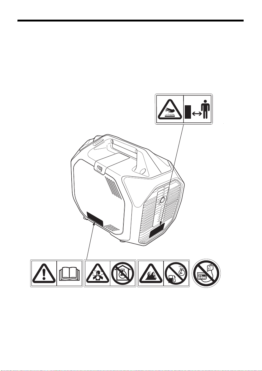
HOT CAUTION
READ OWNER’S
MANUAL
EXHAUST CAUTION FUEL CAUTION CONNECT
CAUTION
SAFETY LABEL LOCATIONS
These labels warn you of potential hazards that can cause serious injury. Read
them carefully.
If a label comes off or becomes hard to read, contact your servicing dealer for a
replacement.
11

GENERATOR SAFETY
SOCKET CAUTION
DO NOT OVER FILL DO NOT TIP
12

GENERATOR SAFETY
• A hot exhaust system can cause serious burns.
Avoid contact if the engine has been running.
• Honda generator is designed to give safe and
dependable service if operated according to
instructions.
Read and understand the Owner’s Manual
before operating the generator. Failure to do so
could result in personal injury or equipment
damage.
• Exhaust contains poisonous carbon monoxide, a
colorless, odorless gas. Breathing carbon
monoxide can cause loss of consciousness and
may lead to death.
• If you run the generator in an area that is
confined, or even partially enclosed area, the air
you breathe could contain a dangerous amount
of exhaust gas.
• Never run your generator inside a garage, house
or near open windows or doors.
• Gasoline is highly flammable and explosive.
Turn the engine off and let it cool before
refueling.
13

GENERATOR SAFETY
• Improper connections to a building’s electrical
system can allow current from the generator to
backfeed into the utility lines.
Such backfeed may electrocute utility company
workers or others who contact the lines during a
power outage, and the generator may explode,
burn, or cause fires when utility power is
restored.
Consult the utility company or a qualified
electrician prior to making any power
connections.
• Do not fill tank past red limit mark.
Overfilling or tipping over the generator
can result in fuel flowing through the vent
tube and causing a leak and fire. You can
be burned or seriously injured.
• Connect and remove the receptacle box for
parallel operation with the engine stopped.
• For single operation, the receptacle box for
parallel operation must be removed.
14

• CE mark, UKCA mark and noise label locations
CE MARK, UKCA MARK and NOISE LABEL
Year of man ufac ture
Name and address of
the manufacturer
Name and address of
authorized representative
Performance class
Quality class
IP code
Dry mass (weight)
NOISE LABEL
GENERATOR SAFETY
Name and address of manufacturer, authorized representative are written in the
“Declaration of Conformity” CONTENT OUTLINE in this Owner’s Manual.
15

INITIAL USE INSTRUCTIONS
MAINTENANCE COVER
MAINTENANCE COVER SCREW
OIL FILLER CAP
UPPER LIMIT
(The oil exists to
the oil filler neck.)
OIL FILLER NECK
DIPSTICK
ENGINE OIL
The generator is shipped WITHOUT OIL in the engine.
1. Place the generator on a level surface.
2. Loosen the maintenance cover screw and remove the maintenance cover.
3. With the generator in a level position, remove the oil filler cap by turning it
counterclockwise.
4. Add enough oil to bring the oil level to the upper limit of the oil filler neck.
SAE10W-30 API service category SE or later (or equivalent) is recommended
for general use; for additional recommendations (see page 17).
Maximum oil capacity: 0.46 L (0.48 US qt, 0.40 Imp qt)
Do not overfill the engine with oil. If the engine is overfilled, the excess oil
may be transferred to the air cleaner housing and air filter.
5. Screw in the oil filler cap securely.
6. Reinstall the maintenance cover and tighten the maintenance cover screw
securely.
16

INITIAL USE INSTRUCTIONS
AMBIENT TEMPERATURE
ENGINE OIL RECOMMENDATIONS
Oil is a major factor affecting performance and service life. Use 4-stroke
automotive detergent oil.
SAE 10W–30 is recommended for general use. Other viscosities shown in the
chart may be used when the average temperature in your area is within the
recommended range.
Lubrication oil specifications necessary to maintain the performance of the
emissions control system: Honda genuine oil.
Read the instructions on the oil container before use.
The SAE oil viscosity and API service category are in the API label on the oil
container. Honda recommends that you use API service category SE or later (or
equivalent) oil.
17

INITIAL USE INSTRUCTIONS
FUEL
Add fuel to the generator in a well-ventilated area. Fuel only outdoors. Keep
gasoline away from appliance, such as pilot lights, barbecues, electric
appliances, power tools, etc. Spilled fuel is not only a fire hazard, it causes
environmental damage. Fuel carefully to avoid spilling fuel. Wipe up spills
immediately. Do not fill the fuel tank above the upper level mark (red) on the
fuel strainer. After fueling, reinstall the fuel tank cap securely.
When appropriate, with the engine stopped, check the fuel level indicator for
the fuel level. If the fuel level is low, wait for the generator to cool off and refill
the fuel tank.
This engine is certified to operate on unleaded gasoline with a research octane
rating of 89 or higher. Refer to "FUEL RECOMMENDATIONS" (see page 20) for
additional fuel recommendations.
Gasoline is highly flammable and
explosive.
You can be burned or seriously injured
when handling fuel.
• Stop the engine and let it cool before
handling fuel.
• Keep heat, sparks, and flame away.
• Handle fuel only outdoors.
• Keep away from your vehicle.
• Wipe up spills immediately.
Fuel can damage paint and plastic. Be careful not to spill fuel when filling your fuel
tank. Damage caused by spilled fuel is not covered under the Warranty.
18
INITIAL USE INSTRUCTIONS
FUEL FILLER CAP
UPPER LEVEL MARK (RED)
TETHER
FUEL STRAINER
FUEL FILLER CAP
1. Remove the fuel filler cap.
2. Fuel carefully to avoid spilling fuel. Do not fill the fuel tank above the upper
level mark (red) on the fuel strainer.
Fuel can damage paint and plastic. Be careful not to spill fuel when filling your fuel
tank. Damage caused by spilled fuel is not covered under the Warranty.
3. After refueling, tighten the fuel filler cap until it clicks.
Move the generator at least 3 meters (10 feet) away from the fueling source and
site before starting the engine.
19

INITIAL USE INSTRUCTIONS
FUEL RECOMMENDATIONS
This engine is certified to operate on unleaded gasoline with a research octane
rating of 89 or higher.
Fuel specification(s) necessary to maintain the performance of the emissions
control system: E10 fuel referenced in EU regulation.
Use unleaded gasoline only, or the catalyzer will lose its effectiveness and
negatively affect exhaust emissions.
Never use gasoline that is stale, contaminated, or mixed with oil. Avoid getting
dirt or water in the fuel tank.
You may use regular unleaded gasoline containing no more than 10% ethanol
(E10) or 5% methanol by volume. In addition, methanol must contain cosolvents
and corrosion inhibitors.
Use of fuels with content of ethanol or methanol greater than shown above may
cause starting and/or performance problems. It may also damage metal, rubber,
and plastic parts of the fuel system.
Engine damage or performance problems that result from using a fuel with
percentages of ethanol or methanol greater than shown above and leaded
gasoline are not covered under the Warranty.
If your equipment will be used on an infrequent basis, refer to the fuel section of
"STORAGE" chapter (see page 62) for additional information regarding fuel
deterioration.
20

CONTROLS & FEATURES
SPARK PLUG MAINTENANCE COVER
MUFFLER
SPARK PLUG
FRAME SERIAL NUMBER
AIR CLEANER
FUEL FILLER CAP
STARTER GRIP
MAINTENANCE COVER
UNDER GRIP
GRIP
COMPONENT & CONTROL LOCATIONS
Use the illustrations on these pages to locate and identify the most frequently
used controls.
21

CONTROLS & FEATURES
INDICATORS
AC RECEPTACLES
(230V 16A)
IT Type
F, G Types
ENGINE SWITCH
ECO THROT TLE
SWITCH
AC CIRCUIT
PROTECTORS
(16A)
PARALLEL
OPERATION
OUTLETS
GROUND TERMINAL
AC RECEPTACLES
(230V 16A)
22

CONTROLS
ENGINE
SWITCH
ON
OFF
STARTER
GRIP
Engine Switch
The engine switch controls the
ignition system.
OFF – Stops the engine.
ON – Running position, and for
starting with the recoil starter.
Starter Grip
Pulling the starter grip operates the
recoil starter to start the engine.
Do not allow the starter grip to snap
back against the generator. Return it
gently to prevent damage to the starter.
CONTROLS & FEATURES
23

CONTROLS & FEATURES
ECO THROTTLE INDICATOR
ECO THROTTLE
SWITCH
Eco Throttle Switch
The Eco Throttle system automatically reduces engine speed when loads are
turned off or disconnected. When appliances are turned on or reconnected, the
engine returns to the proper speed to power the electrical load.
Each time you push the Eco Throttle Switch, the system turns on and off.
If high electrical loads are connected simultaneously, push the Eco Throttle
system to the OFF to reduce voltage changes.
Eco Throttle system ON Indicator lights on (green)
• Recommended to minimize fuel consumption and
further reduce noise levels when less than a full
load is applied to the generator.
Eco Throttle system OFF Indicator lights off
• The Eco Throttle system does not operate.
OVERLOAD RESET:
If the power generation stops due to overload and the overload alarm indicator
is blinking, overload reset is available. After removing the cause of the overload,
power generation can be resumed by pressing and holding the Eco Throttle
switch (for more than 3 seconds).
24

CONTROLS & FEATURES
PARALLEL OPERATION OUTLETS
AC CIRCUIT
PROTECTOR (16A)
(For receptacle No.2)
ON
OFF
PUSH
AC RECEPTACLE
(230V 16A) No. 2
(when pushed in)
AC CIRCUIT
PROTECTOR (16A)
(For receptacle No.1)
AC RECEPTACLE
(230V 16A) No. 1
F, G Types IT Type
AC RECEPTACLE
(230V 16A) No. 2
AC RECEPTACLE
(230V 16A) No. 1
Parallel Operation Outlets
These outlets are used for connecting two EU32i generators for parallel
operation (see page 47 through 49). A Honda approved parallel cable (optional
equipment) is required for parallel operation. This cable can be purchased from
your servicing dealer.
AC Circuit Protector
The AC circuit protectors will automatically switch OFF if there is a short circuit
or a significant overload of the generator at each receptacle. If an AC circuit
protector switches OFF automatically, check that the appliance is working
properly and does not exceed the rated load capacity of the circuit before
resetting the AC circuit protector ON.
25

CONTROLS & FEATURES
GROUND TERMINAL
EARTH MARK
FEATURES
Ground Terminal
The generator ground terminal is connected to the frame of the generator, the
metal non-current-carrying parts of the generator, and the ground terminals of
each receptacle.
Before using the ground terminal, consult a qualified electrician, electrical
inspector, or local agency having jurisdiction for local codes or ordinances that
apply to the intended use of the generator.
The generator produces enough electric power to cause a serious shock or
electrocution if misused.
Be sure to ground the generator when the connected appliance is grounded.
To ground the terminal of the generator, use a copper wire with same or larger
diameter than the cord of the connected appliance.
Use extension cord set with ground conductor when connecting an appliance
with ground conductor.
To identify the Ground pin in the plug, see Receptacle page 76.
26

CONTROLS & FEATURES
FUEL LEVEL INDICATOR
The indicator according to the generator’s fuel level as follows:
80 % or more 60-80 % 40-60 % 20-40 % 20 % or less
OUTPUT INDICATOR (GREEN)
Fuel Level Indicator
The fuel level indicator is a mechanical device that measures the fuel level in the tank.
To provide increased operating time, start with a full tank before operation.
Check the fuel level with the generator on a level surface. Always refuel with the
engine OFF and cool.
Output Indicator
The output indicator (green) is illuminated when the generator is operating
normally. It indicates that the generator is producing electrical power at the
receptacles.
In addition, the output indicator has a simplified hour meter function.
When you start the engine, the indicator blinks according to the generator’s
cumulative operating hours as follows:
• No blinks: 0–100 hours
• 1 blink: 100–200 hours
• 2 blinks: 200–300 hours
• 3 blinks: 300–400 hours
• 4 blinks: 400–500 hours
• 5 blinks: 500 or more hours
27

CONTROLS & FEATURES
OVERLOAD ALARM INDICATOR
(RED)
OIL ALERT/CHECK INDICATOR
(RED)
Overload Alarm (Indicator)
If the generator is overloaded (in excess of 3.2 kVA), or if there is a short circuit in
a connected appliance, the overload alarm indicator (red) will come ON. The
overload alarm indicator (red) will stay ON, and after about 10 seconds, when an
overload or about 5 seconds in case of a short circuit, current to the connected
appliance(s) will shut off, and the output indicator (green) will go OFF. However,
the engine will continue to run.
If the overload alarm indicator (red) blink continuously, press and hold the ECO
Throttle switch to reset it (see page 24).
Oil Alert/Check Indicator
The Oil Alert
insufficient amount of oil in the crankcase. Before the oil level in the crankcase
can fall below a safe limit or in the case of engine overheat, the Oil Alert/Check
indicator (red) comes ON and the Oil Alert system automatically will stop the
engine (the engine switch will remain in the ON position).
If the engine stops or the Oil Alert/Check indicator (red) comes ON when you
pull the starter grip, check the engine oil level (see page 36) before
troubleshooting in other areas. Also, make sure to install the generator on a
level surface.
The engine may stop due to the activating the oil alert system even if the
engine oil level is the normal when the generator is tilted.
If the Oil Alert/Check indicator (red) blink continuously, it suggests an
abnormal, contact your servicing dealer.
system is designed to prevent engine damage caused by an
28

LED Light Patterns
OIL ALERT/CHECK INDICATOR
OVERLOAD ALARM INDICATOR
OUTPUT INDICATOR
CONTROLS & FEATURES
Status Possible cause Output
Indicator
Oil Alert/
Check
Indicator
Overload
Alarm
Indicator
Normal Operating
normally
Malfunction Inverter unit
//
failure etc.
Abnormal Output
/
overcurrent
Inverter unit
overheat
Warning • Engine oil low
• Tilt detection
• Engine overheat
: ON
: OFF
: Blinking
Refer to "TAKING CARE OF UNEXPECTED PROBLEMS" on page 69 for failure
diagnosis.
29

CONTROLS & FEATURES
iOS Android
Bluetooth® Function
The generator is connected to a smartphone via a Bluetooth® connection.
• The range between your Bluetooth® enabled smartphone and the generator
can be maximized when there is a clear, obstruction free, line-of-sight
between devices. The connection distance is also affected by the type of
smartphone used and the surrounding environment, structures, and
electronic interference.
Smartphone application
The Honda “My Generator” smartphone application is for use only with Honda
generators equipped with Bluetooth® technology. The application is able to do
the following convenient functions:
• Remote stop:
Can stop the generator engine from a distance
• Remote change the Eco Throttle system from a
distance
• Remote monitoring:
Displays power output level and remaining
fuel level etc.
• Receive notifications:
Can receive error and maintenance alerts
Downloading the app
Go to the App Store (iOS) or Google Play
(Android) and search for “Honda My Generator” to download the app.
Pairing (For first time connection only)
Refer to the Support on the Honda “My Generator” smartphone application to
pair the smartphone with the generator.
• Perform the pairing operation within 30 seconds after starting the engine.
30

CONTROLS & FEATURES
BLUETOOTH INDICATOR
BLUETOOTH PASSWORD
The indicator according to the Bluetooth® connection as follows:
• OFF: Not connected
• Fast Blinking: Malfunction
• Slow Blinking: Pairing available
• ON: Connected
31

CONTROLS & FEATURES
GRIP
UNDER GRIP
Grip and Under Grip
Use the grip by your hand when lifting the generator.
In addition to using the grip, you can lift the generator using the under grip by
the other hand if necessary.
32
BEFORE OPERATION
ARE YOU READY TO GET STARTED?
Your safety is your responsibility. A little time spent in preparation will
significantly reduce your risk of injury.
Knowledge
Read and understand this manual. Know what the controls do and how to
operate them.
Familiarize yourself with the generator and its operation before you begin using
it. Know how to quickly shut off the generator in case of an emergency.
If the generator is being used to power appliances, be sure that they do not
exceed the generator’s load rating (see pages 46 and 49).
IS YOUR GENERATOR READY TO GO?
For your safety, to ensure compliance with environmental regulations, and to
maximize the service life of your equipment, it is very important to take a few
moments before you operate the generator to check its condition. Be sure to
take care of any problem you find, or have your servicing dealer correct it,
before you operate the generator.
Failure to properly maintain this
generator, or failing to correct a problem
before operation, could result in a
significant malfunction.
Some malfunctions can cause serious
injuries or death.
Always perform a pre-operation
inspection before each operation and
correct any problems.
33

BEFORE OPERATION
To prevent a possible fire, keep the generator at least 1 meter (3 feet) away from
building walls, vehicles, and other equipment during operation. Do not place
flammable objects close to the engine or exhaust.
Before beginning your pre-operation checks, be sure the generator is on a level
and firm surface and the engine switch is in the OFF position.
Check the Engine
• Before each use, look around and underneath the engine for signs of oil or
gasoline leaks.
• Check the engine oil level (see page 36). A low engine oil level will cause the
Oil Alert system to shut down the engine.
• Check the air filters (see page 37). Dirty air filters will restrict air flow to the fuel
system, reducing engine and generator performance.
• Check the fuel level (see page 18). Starting with a full tank will help to
eliminate or reduce operating interruptions for refueling.
AC Appliance and Power Cord
Before connecting an AC appliance or power cord to the generator:
• Use grounded 3-prong extension cords, tools, and appliances, or doubleinsulated tools and appliances.
• Inspect cords and plugs, and replace if damaged.
• Make sure that the appliance is in good working order. Faulty appliances or
power cords can create a potential for electric shock.
• Make sure the electrical rating of the tool or appliance does not exceed the
rated power of the generator or the receptacle being used.
• Do not exceed the current limit specified for any one receptacle.
• When an extension cable is required, be sure to use a tough rubber sheathed
flexible cable (IEC 245 or equivalent).
When using an extension cable the resistance value shall not exceed 1.5 Ω.
34

BEFORE OPERATION
IPx4 PLUG
• Limit length of extension cables; 60 m (200 feet) for cables of 1.5 mm2 (0.0023
2
in
) and 100 m (330 feet) for cables of 2.5 mm2 (0.0039 in2). Long extension
cables will lower usable power due to resistance in the extension cable.
• Keep the generator away from other electric cables or wires such as
commercial power supply lines.
•G Type
WARNING: When connecting an angled plug, be sure to use only a IPx4 plug.
35

BEFORE OPERATION
MAINTENANCE COVER
MAINTENANCE COVER SCREW
OIL FILLER NECK
UPPER LIMIT
(The oil exists to
the oil filler neck.)
OIL FILLER CAP
LOWER LI MIT
(The oil is attached
only to the lower
end of the dipstick.)
DIPSTICK
ENGINE OIL LEVEL CHECK
Check the engine oil level with the generator on a level surface and the engine
stopped.
1. Loosen the maintenance cover screw and remove the maintenance cover.
2. Remove the oil filler cap by turning it counterclockwise. Wipe the dipstick
clean.
3. Insert the dipstick into the oil filler neck as shown, but do not screw it in, then
remove it to check the oil level.
4. If the oil level is near or below the lower limit, fill with the recommended oil
to the upper limit. Do not overfill.
• “Upper limit” means the oil exists to the oil filler neck.
• “Lower limit” means the oil is attached only to the lower end of the
dipstick.
Refer to "ENGINE OIL RECOMMENDATIONS" in page 17.
5. Reinstall the oil filler cap securely.
6. Reinstall the maintenance cover and tighten the maintenance cover screw
securely.
36

BEFORE OPERATION
CLIP
MAINTENANCE COVER
MAINTENANCE COVER SCREW
AIR CLEANER
COVER
PAPER AIR FILTER
FOAM AIR FILTER
GUIDE
The Oil Alert system will automatically stop the engine before the oil level falls
below safe limits. However, to avoid the inconvenience of an unexpected
shutdown, check the oil level regularly.
AIR FILTER CHECK
1. Loosen the maintenance cover
screw and remove the
maintenance cover.
2. Unsnap the air cleaner cover clips;
remove the air cleaner cover.
3. Remove the foam air filter from
the air cleaner cover.
4. Check the foam air filter to be sure they are clean and in good condition. If the
foam air filter are dirty, clean them as described on page 57. Replace the foam
air filter if they are damaged.
5. Reinstall the foam air filter in the air cleaner cover.
6. Remove the paper filter from the guide.
7. If the paper air filter is dirty, replace it with a new one. Do not clean the paper
air filter.
37

BEFORE OPERATION
8. Reinstall the paper air filter, the guide and the air cleaner cover.
9. Reinstall the maintenance cover, and tighten the maintenance cover screw
securely.
Operating the engine without the air filters or with a damaged air filter will allow
dirt to enter the engine, causing rapid engine wear. This type of damage is not
covered by the Warranty.
38

BEFORE OPERATION
SAFE OPERATING PRECAUTIONS
Before operating the generator, review chapters "GENERATOR SAFETY" (see
page 6).
For your safety, do not operate the generator in an enclosed, or partly enclosed
area such as a garage (even if the door is open) or near structures or vehicles.
Your generator's exhaust contains poisonous carbon monoxide gas that can
collect rapidly in such areas, structures, vehicles, trailers, or boats.
• Do not operate the generator when it is in a storage, cargo, or security
enclosure, including any RV generator bay.
• Always completely remove the generator from the vehicle, trailer, boat or
other equipment or structure during operation.
• The generator must remain stationary while in operation.
Exhaust contains poisonous carbon
monoxide gas that can build up to
dangerous levels in enclosed or partly
enclosed areas.
Breathing carbon monoxide can cause
unconsciousness or death.
Never run this product's engine in an
enclosed, or even partly enclosed area.
39

OPERATION
ENGINE SWITCH
ON
STARTING THE ENGINE
To prevent a possible fire, keep the generator at least 1 meter (3 feet) away from
building or trailer walls, vehicles, trailers, boats, and other equipment during
operation. Do not place flammable objects close to the engine or exhaust.
• Operating this generator less than 1 meter (3 feet) from a building, obstruction, or
when it is in an enclosure, a storage or security compartment/bay, can cause
overheating and damage the generator.
• For proper cooling, allow at least 1 meter (3 feet) of empty space above and
around the generator.
Keep all cooling holes open and clear of debris, mud, water, etc. Cooling holes are
located on the side panel, the control panel, and the bottom of the generator. If
the cooling holes are blocked, the generator may overheat and damage the
engine, inverter, or windings.
Refer to "SAFE OPERATING PRECAUTIONS" on page 39 and perform the "IS YOUR
GENERATOR READY TO GO?" checks (see page 33).
Refer to "AC OPERATION" (see page 44) for connecting loads to the generator.
1. Make sure that all appliances are disconnected from the AC receptacle.
2. Turn the engine switch to the ON
position.
40

3. Pull the starter grip lightly until you
STARTER GRIP
ECO THROTTLE SWITCH
Direction to pull
ECO THROTTLE INDICATOR (OFF)
feel resistance; then pull briskly in
the direction of the arrow as shown.
Do not allow the starter grip to snap
back against the generator. Return it
gently to prevent damage to the
starter.
4. If you don't wish to use the Eco
Throttle system, push the Eco
Throttle switch to Eco Throttle
system OFF.
OPERATION
41

OPERATION
ENGINE SWITCH
OFF
PARALLEL CABLE
(optional equipment)
STOPPING THE ENGINE
To stop the engine in an emergency, simply turn the engine switch to the OFF
position securely. Under normal conditions, use the following procedure.
1. Turn off or disconnect all appliances that are connected to the generator.
2. Turn the engine switch to the OFF position securely.
3. If two generators were connected for parallel operation, disconnect the
parallel cable after stopping the engines if you do not wish to resume parallel
operation.
If the generator will not be used for a long period of time, refer to page 64 for
information on "DRAINING THE FUEL TANK".
42

OPERATION
STOPPING THE ENGINE with Bluetooth® ENABLED SMARTPHONE
The engine can be stopped via a Bluetooth® enabled smartphone using a
Bluetooth® application.
Refer to the Bluetooth® application to check the connection, operation, and for
help pairing a smartphone.
43

OPERATION
GROUND TERMINAL
EARTH
MARK
AC OPERATION
If an appliance begins to operate abnormally, becomes sluggish, or stops
suddenly, turn it off immediately. Disconnect the appliance, and determine
whether the problem is in the appliance or the rated load capacity of the
generator has been exceeded.
• Substantial overloading that continuously lights the overload alarm indicator
(red) may damage the generator. Marginal overloading that temporarily lights
the overload alarm indicator (red) may shorten the service life of the generator.
• Be sure that all appliances are in good working order before connecting them to
the generator. Electrical equipment (including lines and plug connections) should
not be defective. If an appliance begins to operate abnormally, becomes sluggish,
or stops suddenly, turn off the generator engine switch immediately. Then
disconnect the appliance, and examine it for signs of malfunction.
The generator produces enough electric power to cause a serious shock or
electrocution if misused.
Be sure to ground the generator when the connected appliance is grounded.
To ground the terminal of the generator,
use a copper wire with same or larger
diameter than the cord of the connected
appliance.
Use extension cord set with ground conductor when connecting an appliance
with ground conductor.
To identify the Ground pin in the plug, see Receptacle page 76.
44

OPERATION
GENERATOR
RCBO
APPLIANCES
Connecting with one RCBO
GENERATOR
RCBO
APPLIANCES
RCBO
Connecting with two RCBO
OVERLOAD ALARM INDICATOR
(RED)
OUTPUT INDICATOR
(GREEN)
Connect a RCBO (Residual current circuit breaker with overload protection) of
30 mA ground fault detection and cut-off of less than 0.4 seconds at more than
30 A of output current, if you are using two or more appliance.
Follow the instructions provided by each RCBO manufacturer before use.
1. Start the engine (see page 40) and make sure the output indicator (green)
comes ON.
2. Plug in the appliance.
45

OPERATION
3. Turn on the appliance.
If the generator is overloaded (see page 46), or if there is a short circuit in a
connected appliance, the overload alarm indicator (red) will go ON. The
overload alarm indicator (red) will stay ON, and after about 10 seconds when an
overload or about 5 seconds in case of a short circuit, current to the connected
appliance(s) will shut off, and the output indicator (green) will go OFF. Stop the
engine and investigate the problem.
Determine if the cause is a short circuit in a connected appliance or an overload.
Correct the problem and restart the generator.
AC Applications
Before connecting an appliance or power cord to the generator:
• Make sure that it is in good working order. A faulty appliance or power cord
can create a potential for electrical shock.
• If an appliance begins to operate abnormally, becomes sluggish, or stops
suddenly, turn it off immediately. Disconnect the appliance, and determine
whether the problem is the appliance or the rated load capacity of the
generator has been exceeded.
Most appliance motors require more than their rated wattage for startup.
Make sure the electrical rating of the tool or appliance does not exceed the
maximum power rating of the generator.
Maximum power is:
3.2 kVA
For continuous operation, do not exceed the rated power.
Rated power is:
2.6 kVA
In either case, the total power requirements (VA) of all appliances connected
must be considered. Appliance and power tool manufacturers usually list rating
information near the model number or serial number.
Substantial overloading that continuously lights the overload alarm indicator (red)
may damage the generator. Marginal overloading that temporarily lights the
overload alarm indicator (red) may shorten the service life of the generator.
46

OPERATION
PAR ALL EL CAB LE
(optional equipment)
AC PARALLEL OPERATION
Before connecting an appliance to either generator, make sure that the
appliance is in good working order and that its electrical rating does not exceed
that of the receptacle.
Most motorized appliances require more than their electrical rating for startup.
When an electric motor is started, the overload alarm indicator (red) may come
ON. This is normal if the overload alarm indicator (red) goes OFF within 4
seconds. If the Oil Alert/Check indicator (red) blink continuously, consult an
authorized Honda servicing dealer.
During parallel operation, the Eco Throttle switch should be in the same
position on both generators.
1. Connect the parallel cable between the two EU32i generators following the
instructions supplied with the cable.
2. Start the engines (see page 40) and make sure the output indicator (green) on
each generator comes ON (see page 44).
47

OPERATION
3. Plug in the appliance following the instruction provided with the parallel
cable.
4. Turn on the appliance.
If the generators are overloaded (see page 49), or if there is a short circuit in a
connected appliance, the overload alarm indicator (red) will go ON. The
overload alarm indicator (red) will stay ON, and after about 10 seconds when an
overload or about 5 seconds in case of a short circuit, current to the connected
appliance(s) will shut off, and the output indicator (green) will go OFF. Stop both
engines and investigate the problem.
Determine if the cause is a short circuit in a connected appliance or an overload.
Correct the problem and restart the generator.
AC Parallel Operation Applications
Follow the instructions included with the parallel cable.
Before connecting an appliance or power cord to the generator:
• Make sure that it is in good working order. A faulty appliance or power cord
can create a potential for electrical shock.
• If an appliance begins to operate abnormally, becomes sluggish, or stops
suddenly, turn it off immediately. Disconnect the appliance, and determine
whether the problem is the appliance or the rated load capacity of the
generator has been exceeded.
• Never connect different generator models and types.
• Use only a Honda approved parallel cable (optional equipment) when
connecting two EU32i generators for parallel operation.
• Never connect or remove the parallel cable when the generator is running.
• For single generator operation, the parallel cable must be removed.
48

OPERATION
Most appliance motors require more than their rated wattage for startup.
Make sure the electrical rating of the tool or appliance does not exceed the
maximum power rating of the generator.
Maximum power in parallel operation is:
6.4 kVA
For continuous operation, do not exceed the rated power.
Rated power in parallel operation is:
5.2 kVA
In either case, the total power requirements (VA) of all appliances connected
must be considered. Appliance and power tool manufacturers usually list rating
information near the model number or serial number.
Substantial overloading that continuously lights the overload alarm indicator (red)
may damage the generator. Marginal overloading that temporarily lights the
overload alarm indicator (red) may shorten the service life of the generator.
49

OPERATION
ECO THROTTLE SWITCH
ECO THROTTLE
INDICATOR (GREEN)
ECO THROTTLE SYSTEM
Each time you push the Eco Throttle Switch, the system turns on and off.
With the system in the ON, engine speed is automatically lowered when loads
are reduced, turned off, or disconnected. When appliances are turned on or
reconnected, the engine returns to the proper speed to power the electrical
load. In the OFF, the Eco Throttle system does not operate.
Appliances with large start-up power demands may not allow the engine to
reach normal operating rpm when they are connected to the generator. Turn
the Eco Throttle system to the OFF and connect the appliance to the generator.
If the engine still will not reach normal operating speed, check that the
appliance does not exceed the rated load capacity of the generator.
If high electrical loads are connected simultaneously, turn the Eco Throttle
system to the OFF to reduce voltage changes.
The Eco Throttle system is not effective for use with appliances or tools that
require only momentary power. If the tool or appliance will be turned ON and
OFF quickly, the Eco Throttle system should be in the OFF.
Eco Throttle system ON Indicator lights on (green)
• Recommended to minimize fuel consumption and
further reduce noise levels when less than a full
load is applied to the generator.
Eco Throttle system OFF Indicator lights off
• The Eco Throttle system does not operate.
50

OPERATION
STANDBY POWER
Connections to a Building’s Electrical System
Connections for standby power to a building’s electrical system must be made
by a qualified electrician. The connection must isolate the generator power
from utility power, and must comply with all applicable laws and electrical
codes.
Improper connections to a building’s
electrical system can allow current from
the generator to backfeed into the
utility lines.
Such backfeed may electrocute utility
company workers or others who contact
the lines during a power outage, and the
generator may explode, burn, or cause
fires when utility power is restored.
Consult the utility company or a
qualified electrician prior to making any
power connections.
In some areas, generators are required by law to be registered with local utility
companies. Check local regulations for proper registration and use procedures.
System Ground
This generator has a system ground that connects the generator frame
components to ground terminals in the AC output receptacles. The system
ground is not connected to the AC neutral wire.
51

OPERATION
Special Requirements
Do not lay the generator on its side when moving, storing, or operating it. Oil and
fuel may leak and damage the engine or your property.
There may be applicable laws, local codes, or ordinances that apply to the
intended use of the generator. Please consult a qualified electrician, electrical
inspector, or the local agency having jurisdiction.
• In some areas, generators are required to be registered with local utility
companies.
• If the generator is used at a construction site, there may be additional
regulations that must be observed.
52

SERVICING YOUR GENERATOR
THE IMPORTANCE OF MAINTENANCE
Good maintenance is essential for safe, economical, and trouble-free operation.
It will also help reduce air pollution.
To help you properly care for your generator, the following pages include a
maintenance schedule, routine inspection procedures, and simple maintenance
procedures using basic hand tools. Other service tasks that are more difficult or
require special tools are best handled by professionals and are normally
performed by a Honda technician or other qualified mechanic.
The maintenance schedule applies to normal operating conditions. If you
operate your generator under unusual conditions, such as sustained high-load
or high-temperature operation, or use it in dusty conditions, consult your
servicing dealer for recommendations applicable to your individual needs and
use.
Failure to properly maintain this
generator, or failing to correct a problem
before operation, could result in a
significant malfunction.
Some malfunctions can cause serious
injuries or death.
Always follow the inspection and
maintenance recommendations and
schedules in this owner’s manual.
Remember that an authorized Honda servicing dealer knows your generator
best and is fully equipped to maintain and repair it.
To ensure the best quality and reliability, use only new, Honda Genuine parts or
their equivalents for repair and replacement.
53

SERVICING YOUR GENERATOR
MAINTENANCE SAFETY
Some of the most important safety precautions follow. However, we cannot
warn you of every conceivable hazard that can arise in performing
maintenance. Only you can decide whether or not you should perform a given
task.
Improper maintenance can cause an
unsafe condition.
Failure to properly follow maintenance
instructions and precautions can cause
serious injuries or death.
Always follow the procedures and
precautions in this owner’s manual.
Safety Precautions
Read the instructions before you begin, and make sure you have the tools and
skills required.
• Make sure the engine is off before you begin any maintenance or repairs. This
will eliminate several potential hazards:
– Carbon monoxide poisoning from engine exhaust
Operate outside away from open windows or doors with engine exhaust
directed away from occupied structures.
– Burns from hot parts
Let the engine and exhaust system cool before touching.
– Injury from moving parts
Do not run the engine unless instructed to do so.
• To reduce the possibility of fire or explosion, be careful when working around
gasoline. Use only a non-flammable solvent, not gasoline, to clean parts. Keep
cigarettes, sparks, and flames away from all fuel-related parts.
54

SERVICING YOUR GENERATOR
MAINTENANCE SCHEDULE
Failure to follow this maintenance schedule could result in non-warrantable
failures.
REGULAR SERVICE PERIOD (3)
Perform at every indicated month
or operating hour interval,
whichever comes first.
ITEM
Engine oil Check level o 36
Change (first time
from purchase)
Change o 56
Air cleaner (element) Check o 37
Clean o (1) 57
Replace o 37
Spark plug Check-adjust o 58
Replace o 58
Spark arrester Clean o 60
Timing belt Check After every 250 hrs. (2) —
Valve clearance Check-adjust o (2) —
Combustion chamber Clean After every 500 hrs. (2) —
Fuel tank Clean Every 2 years or 1,000 hrs. (2) —
Fuel pump filter Replace Every 2 years or 1,000 hrs. (2) —
Fuel tube Check Every 2 years (Replace if necessary) (2) —
Canister Check Every 2 years (Replace if necessary) (2) —
Purge tube Check Every 2 years (Replace if necessary) (2) —
Charge tube Check Every 2 years (Replace if necessary) (2) —
Air tube Check Every 2 years (Replace if necessary) (2) —
Drain tube Check Every 2 years (Replace if necessary) (2) —
(1) Service more frequently when used in dusty areas.
(2) These items should be serviced by your servicing dealer, unless you have the proper tools and are
mechanically proficient. Refer to the Honda shop manual for service procedures.
(3) For commercial use, log hours of operation to determine proper maintenance intervals.
Each
use
First
month
20 Hrs.
Every
months
or
50 Hrs.
o56
Every
3
months
or
100 Hrs.
Every
year
6
or
or
300 Hrs.
Page
This generator is equipped with a catalytic converter. If the engine is not properly maintained, the catalyst in
the muffler may lose effectiveness.
55

SERVICING YOUR GENERATOR
OIL FILLER NECK
UPPER LIMIT
(The oil exists to
the oil filler neck.)
OIL FILLER CAP
ENGINE OIL CHANGE
Drain the oil while the engine is warm to assure rapid and complete draining.
1. Turn the engine switch to the OFF position (see page 42) to reduce the
possibility of fuel leakage.
2. Loosen the maintenance cover screw and remove the maintenance cover
(see page 36).
3. Place a suitable container next to the engine to catch the used oil.
4. Remove the oil filler cap, and drain the oil into the container by tipping the
engine toward the oil filler neck.
Improper disposal of engine oil can be harmful to the environment. If you change
your own oil, please dispose of the used oil properly.
Do not discard it in a trash bin, dump it on the ground, or pour it down the drain.
5. With the generator in a level position, fill with the recommended oil to the
upper limit. Do not overfill.
• “Upper limit” means the oil exists to the oil filler neck. Refer to "ENGINE OIL
RECOMMENDATIONS" in page 17.
Maximum oil capacity: 0.46 L (0.48 US qt, 0.40 Imp qt)
6. Reinstall the oil filler cap securely.
7. Reinstall the maintenance cover and tighten the maintenance cover screw
securely.
Wash your hands with soap and water after handling used oil.
56

SERVICING YOUR GENERATOR
Clean
Squeeze and dry
Dip in oil
Squeeze
Do not twist. Do not twist.
AIR CLEANER SERVICE
Foam Air Filter Cleaning
A dirty foam air filter will restrict air flow to the fuel system, reducing engine
performance. If you operate the generator in very dusty areas, clean the foam
air filter more frequently than specified in the Maintenance Schedule.
1. Clean the foam air filter in warm soapy water, rinse, and allow to dry
thoroughly, or clean in nonflammable solvent and allow to dry.
2. Dip the foam air filter in clean engine oil, and then squeeze out all excess oil.
The engine will smoke when started if too much oil is left in the filter.
3. Wipe dirt from inside of the air cleaner cover using a moist rag.
Be careful to prevent dirt from entering the air duct that leads to the fuel
system.
57

SERVICING YOUR GENERATOR
SPARK PLUG
MAINTENANCE
COVE R
SPARK PLUG CAP
SPARK PLUG WRENCH
SPARK PLUG CAP
SPARK PLUG SERVICE
Recommended spark plug: CR6HSB (NGK)
To ensure proper engine operation, the spark plug must be properly gapped
and free of deposits.
An incorrect spark plug can cause engine damage.
If the engine is hot, allow it to cool before servicing the spark plug.
1. Remove the spark plug maintenance cover.
2. Disconnect the spark plug cap, and remove any dirt from around the spark
plug area.
3. Remove the spark plug with a spark plug wrench.
58

SERVICING YOUR GENERATOR
SIDE ELECTRODE
SEALING WASHER
0.6–0.7 mm
(0.024–0.028 in)
INSULATOR
4. Inspect the spark plug. Replace it if
the electrodes are worn or fouled, or
if the insulator is cracked or chipped.
Clean the spark plug with a wire
brush if it is to be reused.
5. Measure the spark plug electrode
gap with a wire-type feeler gauge.
Correct the gap, if necessary, by
carefully bending the side electrode.
Spark plug gap:
0.6–0.7 mm (0.024–0.028 in)
6. Make sure that the spark plug sealing washer is in good condition, and thread
the spark plug in by hand to prevent cross-threading.
7. After the spark plug is seated, tighten with a spark plug wrench to compress
the washer.
If reinstalling a used spark plug, tighten 1/8–1/4 turn after the spark plug is
seated.
If installing a new spark plug, tighten 1/2 turn after the spark plug is seated.
Torque: 12 N∙m (1.2 kgf∙m, 9 lbf∙ft)
A loose spark plug can overheat and damage the engine.
Overtightening the spark plug can damage the threads in the cylinder head.
8. Reinstall the spark plug cap on the spark plug securely.
9. Reinstall the spark plug maintenance cover.
59

SERVICING YOUR GENERATOR
MUFFLER PROTECTOR
6 mm SCREWS
REAR COVER
6×15 mm SCREWS
6×15 mm SCREWS
6 mm SCREW 6×15 mm SCREW
SPARK ARRESTER SERVICE
If the engine has been running, the muffler will be very hot. Allow the muffler to
cool before servicing the spark arrester.
Clean the spark arrester as follows:
1. Remove the two 6×15 mm screws, and the rear cover.
Remove the two 6 mm screws, two 6×15 mm screws and the muffler
protector.
60

SERVICING YOUR GENERATOR
SPARK ARRESTER
4 mm SCREW
2. Remove the 4 mm screw, and the spark arrester.
3. Use a brush to remove carbon deposits from the spark arrester screen.
Be careful to avoid damaging the screen.
The spark arrester must be free of breaks and tears. Replace the spark arrester
if it is damaged.
4. Install the spark arrester, the muffler protector, and the rear cover in the
reverse order of removal.
61

STORAGE
STORAGE PREPARATION
Proper storage preparation is essential for keeping your generator trouble-free
and looking good. The following steps will help to keep rust and corrosion from
impairing your generator’s function and appearance, and will make the engine
easier to start when you use the generator again.
Cleaning
Wipe the generator with a moist cloth. After the generator has dried, touch up
any damaged paint, and coat other areas that may rust with a light film of oil.
Fuel
Depending on the region where you operate your equipment, fuel formulations may
deteriorate and oxidize rapidly. Fuel deterioration and oxidation can occur in as
little as 30 days and may cause damage to the fuel system. Please check with your
servicing dealer for local storage recommendations.
Gasoline will oxidize and deteriorate in storage. Old gasoline will cause hard
starting, and it leaves gum deposits that clog the fuel system. If the gasoline in
your generator deteriorates during storage, you may need to have the fuel
system components serviced or replaced.
The length of time that gasoline can be left in your fuel tank without causing
functional problems will vary with such factors as gasoline blend, your storage
temperatures, and whether the fuel tank is partly or completely filled. The air in
a partly filled fuel tank promotes fuel deterioration. Very warm storage
temperatures accelerate fuel deterioration. Fuel deterioration problems may
occur within a few months, or even less if the gasoline was not fresh when you
filled the fuel tank.
62

STORAGE
Service according to the table below:
STORAGE TIME RECOMMENDED SERVICE PROCEDURE TO
PREVENT HARD STARTING
Less than 1 month No preparation required.
1 month to 1 year Drain the fuel tank (see page 64).
1 year or more Drain the fuel tank (see page 64).
Remove the spark plug. Put a teaspoon of engine oil
into the cylinder. Turn the engine slowly with the
pull rope to distribute the oil.
Reinstall the spark plug.
Change the engine oil (see page 56).
63

STORAGE
FUEL STRAINER
PUMP GUARD
HAND PUMP
DRAINING THE FUEL TANK
Gasoline is highly flammable and
explosive.
You can be burned or seriously injured
when handling fuel.
• Stop the engine and let it cool before
handling fuel.
• Keep heat, sparks, and flame away.
• Handle fuel only outdoors.
• Keep away from your vehicle.
• Wipe up spills immediately.
Unscrew the fuel filler cap (see page 19), remove the fuel strainer, and empty the
fuel tank into an approved gasoline container. We recommend using a
commercially available gasoline hand pump to empty the tank. Do not use an
electric pump. Siphon the gasoline by inserting the tip of the hand pump into
the side of the pump guard, as shown in the figure below. Reinstall the fuel
strainer and the fuel filler cap.
64

Engine Oil
Change the engine oil (see page 56).
Engine Cylinder
1. Remove the spark plug (see page 58).
STORAGE
2. Pour a teaspoon (5 cm
3. Pull the starter rope several times to distribute the oil in the cylinder.
4. Reinstall the spark plug (see page 58).
5. Slowly pull the starter grip until resistance is felt. At this point, the piston is
coming up on its compression stroke and both the intake and exhaust valves
are closed. Storing the engine in this position will help to protect it from
internal corrosion. Return the starter grip gently.
3
) of clean engine oil into the cylinder.
65

STORAGE
STORAGE PRECAUTIONS
If your generator will be stored with gasoline in the fuel tank, it is important to
reduce the hazard of gasoline vapor ignition.
Select a well-ventilated storage area away from any appliance that operates
with a flame, such as a furnace, water heater, or clothes dryer.
Also, avoid any area with a spark-producing electric motor, or where power
tools are operated.
If possible, avoid storage areas with high humidity, because that promotes rust
and corrosion.
Place the generator on a level surface. Tilting or laying it on its side can cause
fuel or oil leakage.
With the engine and exhaust system cool, cover the generator to keep out dust.
A hot engine and exhaust system can ignite or melt some materials.
Do not use a plastic sheet as a dust cover. A nonporous cover will trap moisture
around the generator, promoting rust and corrosion.
REMOVAL FROM STORAGE
Check your generator as described in the "BEFORE OPERATION" chapter of this
manual (see page 33).
If the fuel was drained during storage preparation, fill the fuel tank with fresh
gasoline. If you keep a container of gasoline for refueling, be sure that it
contains only fresh gasoline. Gasoline oxidizes and deteriorates over time,
causing hard starting.
If the cylinder was coated with oil during storage preparation, the engine may
smoke briefly at startup. This is normal.
66

TRANSPORTING
An engine that has been running will
remain very hot for a period of time.
A hot engine and exhaust system can
burn you and ignite some material.
If the generator has been used, allow it
to cool for at least 15 minutes before
loading the generator on the transport
vehicle.
Drain the fuel from the fuel tank when transporting.
To prevent spillage when transporting, the generator should be secured upright
in its normal operating position.
Do not lay the generator on its side when moving, storing, or operating it. Oil or fuel
may leak and damage the engine or your property.
Do not operate the generator while it is being transported or while it is
mounted to any type of vehicle, trailer, or boat.
Take care not to drop or strike the generator when transporting. Do not place
heavy objects on the generator.
67

TRANSPORTING
HOLDING PART
To transport the generator, hold the holding part (shaded areas in the figure
below).
Avoid a place exposed to direct sunlight when putting the generator on a
vehicle. If the generator is left in an enclosed vehicle for many hours, high
temperature inside the vehicle could cause fuel to vaporize resulting in a
possible explosion.
68

TAKING CARE OF UNEXPECTED PROBLEMS
ENGINE SPEED IS UNSTABLE OR WILL NOT START
Possible Cause Correction
Engine switch is in the OFF position. Turn engine switch to the ON position
(see page 40).
Out of fuel. Refuel (see page 18).
Bad fuel; generator stored without
treating or draining gasoline, or
refueled with bad gasoline.
Low engine oil level caused Oil Alert to
stop engine.
Spark plug faulty, fouled, or
improperly gapped.
Spark plug wet with fuel
(flooded engine).
Fuel filter restricted, fuel system
malfunction, fuel pump failure,
ignition malfunction, valves stuck, etc.
Drain fuel tank (see page 64).
Refuel with fresh gasoline
(see page 18).
Turn the engine switch to the OFF
position. Add engine oil. Then turn the
engine switch to the ON position and
restart the engine.
Gap or replace spark plug
(see page 58).
Dry and reinstall spark plug.
Take the generator to your servicing
dealer, or refer to the shop manual.
69

TAKING CARE OF UNEXPECTED PROBLEMS
ENGINE LACKS POWER
Possible Cause Correction
Air filter restricted. Clean or replace air filter (see page 57).
Bad fuel; generator stored without
treating or draining gasoline, or
refueled with bad gasoline.
Fuel filter restricted, fuel system
malfunction, fuel pump failure,
ignition malfunction, valves stuck, etc.
NO POWER AT THE AC RECEPTACLES
Possible Cause Correction
Output indicator is OFF, and overload
alarm indicator is ON.
Overload alarm indicator blink. After removing the cause of the
AC circuit protector tripped. Check AC load and reset circuit
Faulty power tool or appliance. Replace or repair power tool or
Faulty generator. Take the generator to your servicing
Drain fuel tank (see page 64).
Refuel with fresh gasoline
(see page 18).
Take the generator to your servicing
dealer, or refer to the shop manual.
Check AC load. Stop and restart the
engine.
Check the cooling air inlet. Stop and
restart the engine.
overload, power generation can be
resumed by pressing and holding the
Eco Throttle switch (for more than 3
seconds) (see page 24).
protector (see page 25).
appliance.
Stop and restart the engine.
dealer, or refer to the shop manual.
70

TECHNICAL INFORMATION
FRAME SERIAL NUMBER
QR CODE
SERIAL NUMBER LOCATION
Record the frame serial number and date purchased in the spaces below. You
will need this information when ordering parts and when making technical or
warranty inquiries.
Frame serial number:
Date purchased:
71

TECHNICAL INFORMATION
SPECIFICATIONS
Dimensions
Model EU32i
Type F, G IT
Description code EBKJ
Length 571 mm (22.5 in) 596 mm (23.5 in)
Width 306 mm (12.0 in)
Height 452 mm (17.8 in)
Dry mass [weight] 26.5 kg (58.4 lbs)
Engine
Model GX130
Engine type 4-stroke, overhead camshaft, single cylinder
Displacement
[Bore × Stroke]
130 cm
[56.0 × 53.0 mm (2.20 × 2.09 in)]
Compression ratio 10.0 : 1
Engine speed
4,800 – 5,500 min
(with Eco Throttle system OFF)
Cooling system Forced air
Ignition system Full transistor
Engine oil capacity 0.46 L (0.48 US qt, 0.40 Imp qt)
Fuel tank capacity 4.6 L (1.21 US gal, 1.01 Imp gal)
Spark plug CR6HSB (NGK)
3
(7.93 cu-in)
-1
(rpm)
[Carbon dioxide (CO2) emissions
*
]
Please refer to "CO2 Information List" on
www.honda-engines-eu.com/co2
* The CO2 measurement results from testing over a fixed test cycle under laboratory conditions
a(n) (parent) engine representative of the engine type (engine family) and shall not imply or
express any guarantee of the performance of a particular engine.
72

TECHNICAL INFORMATION
Generator
Model EU32i
Type F, G, IT
AC output Rated voltage 230 V
Rated frequency 50 Hz
Rated current 11.3 A
Rated output 2.6 kVA
Maximum output 3.2 kVA
Communication
Bluetooth® version 5.0 (Bluetooth Low Energy)
Frequency band (s) 2,402 MHz - 2,480 MHz
Maximum radio-frequency power
<4 dBm
73

TECHNICAL INFORMATION
Microphone point
CONT ROL
PAN EL
Center
1.0 m
1.60 m
Noise
Model EU32i
Type F, G, IT
Sound pressure level at the workstation
(2006/42/EC)
Uncertainty 4 dB (A)
Measured sound power level
(2000/14/EC, 2005/88/EC)
Uncertainty 3 dB (A)
Guaranteed sound power level
(2000/14/EC, 2005/88/EC)
73 dB (A)
(with Eco throttle ON)
88 dB (A)
(with Eco throttle ON)
91 dB (A)
(with Eco throttle ON)
‘‘the figures quoted are emission levels and are not necessarily safe working
levels. Whilst there is a correlation between the emission and exposure levels,
this cannot be used reliably to determine whether or not further precautions
are required. Factors that influence the actual level of exposure of work-force
include the characteristics of the work room, the other sources of noise, etc. i.e.
the number of machines and other adjacent processes, and the length of time
for which an operator is exposed to the noise. Also the permissible exposure
level can vary from country. This information, however, will enable the user of
the machine to make a better evaluation of the hazard and risk’’.
Specifications may vary according to the types, and are subject to change
without notice.
74

Wiring Diagram
Abbreviations
Symbol Part name
ACCP
ACOR
BASe
CPB
EcoSw
ECG
ECU
EgB
EgG
ESw
(F)
FrB
FP
GCU
GeB
GT
IASe
IB
IgC
In
IndU
(IT)
IU
MASe
MW
NF
OLSw
O2Se
PC
POR
SP
SW
TCM
TESe
AC Circuit Protector
AC Output Receptacle
Bank Angle Sensor
Control Panel Block
Eco Throttle Switch
ECU Ground
ECU
Engine Block
Engine Ground
Engine Switch
F Type
Frame Block
Fuel Pump
Generator Control Unit
Generator Block
Ground Terminal
IAT Sensor
Inverter Block
Ignition Coil
Injector
Indicator Unit
IT Type
Inverter Unit
MAP Sensor
Main Winding
Noise Filter
Oil Level Switch
O2 Sensor
Pulser Coil
Parallel Operation
Receptacle
Spark Plug
Sub Winding
Throttle Control Motor
TE Sensor
Wire color code
ECO THROTTLE SW
ENG STOP SW
Bl
Br
G
Gr
Bu
Lb
Lg
O
P
R
W
Y
V
BE
Black
Brown
Green
Gray
Blue
Light blue
Light green
Orange
Pink
Red
White
Yellow
Violet
Beige
COM SW
PUSH
FREE
COM SW
ON
OFF
(See inside back cover)
TECHNICAL INFORMATION
75

TECHNICAL INFORMATION
GROUND PIN
GROUND PIN
GROUND PIN
Receptacle
Type Shape Plug
F
G
IT
76

REFERENCE INFORMATION
“QR Code” is registered trademark of DENSO WAVE INCORPORATED.
The Bluetooth word mark and logos are registered trademarks owned by
Bluetooth SIG, Inc., and any use of such marks by Honda Motor Co., Ltd., is under
license. Other trademarks and trade names are those of their respective owners.
77

MEMO
78

Honda EU32i
MANUEL DE L’UTILISATEUR
Notice originale

Les gaz d’échappement contiennent du
monoxyde de carbone, un gaz toxique
qui peut s’accumuler à des niveaux
dangereux dans des endroits clos ou
partiellement clos.
L’inhalation de monoxyde de carbone
peut provoquer des évanouissements
ou la mort.
Ne faites jamais tourner le moteur du
produit dans un endroit clos, même
partiellement.
Gardez le présent manuel de l’utilisateur à portée de main afin de pouvoir le
consulter à tout moment.
Le présent manuel de l’utilisateur doit être considéré comme un élément
permanent du groupe électrogène et doit l’accompagner en cas de revente.
Les informations et caractéristiques figurant dans cette publication étaient
effectives au moment de la mise sous presse. Honda Motor Co., Ltd. se réserve
toutefois le droit d’arrêter ou de modifier à tout moment les caractéristiques ou
la conception sans préavis et sans aucune obligation de sa part.
Les illustrations peuvent varier en fonction du type.

INTRODUCTION
Nous vous remercions d’avoir porté votre choix sur un groupe électrogène
Honda.
Nous désirons vous aider à faire le meilleur usage de votre nouveau groupe
électrogène et à l’utiliser en sécurité. Vous trouverez dans ce manuel des
informations sur la manière d’y parvenir : Lisez-le attentivement.
Nous vous conseillons de lire le bulletin de garantie afin de bien comprendre
l’étendue de la garantie et vos responsabilités en tant que propriétaire.
Lorsque votre groupe électrogène a besoin d’une intervention prévue dans le
programme d’entretien, n’oubliez pas que votre concessionnaire Honda est
spécialement formé pour l’entretien des groupes électrogènes Honda. Votre
concessionnaire réparateur Honda n’épargnera aucun effort pour vous donner
satisfaction et se fera un plaisir de répondre à toutes vos questions et
préoccupations.
1

INTRODUCTION
REMARQUE
QUELQUES MOTS SUR LA SÉCURITÉ
Votre sécurité et la sécurité des autres sont capitales.
Des messages de sécurité importants sont inclus dans le présent manuel et
apposés sur le groupe électrogène. Ils vous informent des risques qui peuvent
exister pour vous ou les autres. Veuillez lire attentivement ces messages.
Il ne nous est naturellement pas possible de vous avertir de tous les risques
associés à l’utilisation ou à l’entretien d’un groupe électrogène. Vous devez faire
appel à votre propre jugement.
Des informations de sécurité importantes vous sont communiquées sous
diverses formes :
• Étiquettes de sécurité — apposées sur le groupe électrogène.
• Instructions — comment utiliser ce groupe électrogène correctement et en
toute sécurité.
• Rubriques de sécurité — telles que le paragraphe INFORMATIONS DE
SÉCURITÉ IMPORTANTES.
• Messages de sécurité — précédés d’un symbole de mise en garde et de
l’un des trois mots-indicateurs DANGER, AVERTISSEMENT ou ATTENTION.
Ces mots-indicateurs signifient :
Le non-respect de ces instructions ENTRAÎNERA des
BLESSURES GRAVES voire MORTELLES.
Le non-respect de ces instructions est SUSCEPTIBLE
d’entraîner des BLESSURES GRAVES voire MORTELLES.
Le non-respect de ces instructions est SUSCEPTIBLE
d’entraîner des BLESSURES.
Le manuel tout entier contient des informations de sécurité importantes lisez-le attentivement.
MESSAGES DE PRÉVENTION DES DOMMAGES
Vous trouverez également des informations précédées d’un symbole .
Ces informations ont pour but de vous aider à éviter les dommages au niveau de
votre groupe électrogène, d’autres biens ou de l’environnement.
2

SOMMAIRE
INTRODUCTION ................................................................................................ 1
SÉCURITÉ DU GROUPE ÉLECTROGÈNE............................................................ 6
INFORMATIONS DE SÉCURITÉ IMPORTANTES..............................................................6
Responsabilités de l’opérateur .....................................................................................6
Dangers du monoxyde de carbone ............................................................................7
Risques de décharge électrique ...................................................................................8
Risques d’incendie et de brûlures................................................................................9
Faire le plein de carburant avec précaution ............................................................9
Antidéflagrant...................................................................................................................10
Risques liés aux véhicules et au transport ..............................................................10
Mise au rebut.....................................................................................................................10
Mise au rebut du groupe électrogène .....................................................................10
EMPLACEMENT DES ÉTIQUETTES DE SÉCURITÉ.........................................................11
CONSIGNES POUR LA PREMIÈRE UTILISATION ............................................ 16
HUILE MOTEUR ......................................................................................................................16
RECOMMANDATIONS POUR L’HUILE MOTEUR..........................................................17
CARBURANT............................................................................................................................18
RECOMMANDATIONS POUR LE CARBURANT.............................................................20
COMMANDES ET FONCTIONS........................................................................21
EMPLACEMENT DES COMPOSANTS ET COMMANDES............................................21
COMMANDES.........................................................................................................................23
Commutateur principal.................................................................................................23
Poignée de lancement...................................................................................................23
Interrupteur Eco-Throttle..............................................................................................24
Sorties de fonctionnement en parallèle..................................................................25
Protecteur de circuit CA ................................................................................................25
FONCTIONS.............................................................................................................................26
Borne de masse ................................................................................................................26
Jauge de carburant .........................................................................................................27
Témoin de sortie ..............................................................................................................27
Alarme de surcharge (témoin)....................................................................................28
Témoin d’alerte/de vérification d’huile ...................................................................28
Fonction Bluetooth®........................................................................................................29
Application pour smartphone ....................................................................................29
Schémas de l’éclairage LED..........................................................................................31
Poignée et poignée inférieure ....................................................................................32
3

SOMMAIRE
AVANT UTILISATION ...................................................................................... 33
ÊTES-VOUS PRÊT À DÉMARRER ?.....................................................................................33
Acquisition des connaissances ...................................................................................33
LE GROUPE ÉLECTROGÈNE EST-IL PRÊT À FONCTIONNER ?..................................33
Vérification du moteur...................................................................................................34
Appareil ou cordon d’alimentation CA....................................................................34
VÉRIFICATION DU NIVEAU D’HUILE MOTEUR.............................................................36
VÉRIFICATION DU FILTRE À AIR........................................................................................37
CONSIGNES DE SÉCURITÉ D’UTILISATION....................................................................39
UTILISATION ................................................................................................... 40
DÉMARRAGE DU MOTEUR.................................................................................................40
ARRÊT DU MOTEUR..............................................................................................................42
ARRÊT DU MOTEUR AVEC UN SMARTPHONE Bluetooth®.......................................43
UTILISATION DU COURANT ALTERNATIF.....................................................................44
Applications CA................................................................................................................46
UTILISATION DU COURANT ALTERNATIF AVEC FONCTIONNEMENT EN
PARALLÈLE .........................................................................................................................47
Applications CA avec fonctionnement en parallèle............................................48
SYSTÈME ECO-THROTTLE...................................................................................................50
ALIMENTATION DE SECOURS ...........................................................................................51
Raccordement au système électrique d’un bâtiment ........................................51
Masse du système............................................................................................................51
Prescriptions spéciales...................................................................................................52
ENTRETIEN DU GROUPE ÉLECTROGÈNE ....................................................... 53
IMPORTANCE DE L’ENTRETIEN.........................................................................................53
SÉCURITÉ D’ENTRETIEN.......................................................................................................54
Consignes de sécurité....................................................................................................54
PROGRAMME D’ENTRETIEN ..............................................................................................55
VIDANGE DE L’HUILE MOTEUR.........................................................................................56
ENTRETIEN DU FILTRE À AIR..............................................................................................57
Nettoyage du filtre à air en mousse..........................................................................57
ENTRETIEN DE LA BOUGIE D’ALLUMAGE.....................................................................58
ENTRETIEN DU PARE-ÉTINCELLES...................................................................................60
4

SOMMAIRE
STOCKAGE....................................................................................................... 62
PRÉPARATION AU STOCKAGE ..........................................................................................62
Nettoyage...........................................................................................................................62
Carburant............................................................................................................................62
Huile moteur......................................................................................................................65
Cylindre du moteur.........................................................................................................65
PRÉCAUTIONS DE STOCKAGE...........................................................................................66
FIN DU STOCKAGE................................................................................................................66
TRANSPORT..................................................................................................... 67
EN CAS DE PROBLÈME INATTENDU............................................................... 69
LE MOTEUR NE DÉMARRE PAS.........................................................................................69
LE MOTEUR MANQUE DE PUISSANCE ...........................................................................70
PAS DE COURANT AUX PRISES CA..................................................................................70
INFORMATIONS TECHNIQUES .......................................................................71
EMPLACEMENT DES NUMÉROS DE SÉRIE.....................................................................71
CARACTÉRISTIQUES TECHNIQUES..................................................................................72
INFORMATIONS DE RÉFÉRENCE .................................................................... 77
SUPPLÉMENT ........................................................................ à la fin du manuel
• SCHEMA DE CABLAGE
• ADRESSES DES PRINCIPAUX DISTRIBUTEURS Honda
• "UK-Declaration de conformite" DESCRIPTION DE TABLE DES MATIERES
• "CE-Declaration de conformite" DESCRIPTION DE TABLE DES MATIERES
5

SÉCURITÉ DU GROUPE ÉLECTROGÈNE
INFORMATIONS DE SÉCURITÉ IMPORTANTES
Les groupes électrogènes Honda sont destinés à alimenter des équipements
électriques ayant une puissance requise appropriée. Toute autre utilisation peut
entraîner des blessures de l’opérateur ou endommager le groupe électrogène et
d’autres biens.
La plupart des blessures ou dommages peuvent être évités si vous respectez
toutes les instructions figurant dans le présent manuel et sur le groupe
électrogène. Les dangers les plus courants sont décrits ci-dessous avec
l’indication des meilleurs moyens pour s’en protéger, soi-même et les autres.
Responsabilités de l’opérateur
• N’essayez jamais de modifier le groupe électrogène. Il pourrait en résulter un
accident, ainsi que des dommages au groupe électrogène et aux appareils.
L’altération du moteur annule l’homologation européenne de ce dernier.
– Ne raccordez pas de rallonge au silencieux.
– Ne modifiez pas le système d’admission.
– Ne réglez pas le régulateur de régime.
– Ne déposez pas le panneau de commande et ne modifiez pas son câblage.
• Apprenez à arrêter rapidement le groupe électrogène en cas d’urgence.
• Assimilez bien l’utilisation de toutes les commandes du groupe électrogène,
prises de sortie et connexions.
• Veillez à ce que toutes les personnes utilisant le groupe électrogène reçoivent
des instructions appropriées.
• Protégez les enfants en les maintenant à une distance sûre du groupe
électrogène.
• Observez les instructions du présent manuel sur la manière d’utiliser le
groupe électrogène, ainsi que les informations d’entretien. Le non-respect
des instructions peut entraîner un accident tel qu’une décharge électrique et
une dégradation de l’état des gaz d’échappement.
• Ne faites pas fonctionner le groupe électrogène avec un couvercle retiré.
Vous vous exposez à un accident si votre main ou votre pied se prend dans le
groupe électrogène.
6

SÉCURITÉ DU GROUPE ÉLECTROGÈNE
• Pour les opérations de démontage et les interventions sur le groupe
électrogène non couvertes par le présent manuel, consultez votre
concessionnaire Honda agréé.
• Respectez toutes les législations et réglementations applicables du lieu où le
groupe électrogène est utilisé.
• L’essence et l’huile sont toxiques. Suivez les instructions fournies par chaque
fabricant avant l’emploi.
• Avant utilisation, placez le groupe électrogène sur une surface horizontale et
ferme.
Dangers du monoxyde de carbone
Les gaz d’échappement du groupe électrogène contiennent du monoxyde de
carbone, un gaz toxique, incolore et inodore. L’inhalation de monoxyde de
carbone peut VOUS TUER EN QUELQUES MINUTES. Pour éviter l’intoxication au
monoxyde de carbone, respectez les consignes suivantes lors de l’utilisation
d’un groupe électrogène :
• Faites uniquement fonctionner le groupe électrogène À L’EXTÉRIEUR,
à distance des fenêtres, des portes et des aérations, avec les gaz
d’échappement du moteur non orientés vers des structures occupées.
• Ne faites jamais fonctionner le groupe électrogène dans une maison,
un garage, un sous-sol, un vide sanitaire, dans quelque type de véhicule, de
remorque ou de bateau que ce soit ou dans des endroits clos ou
partiellement clos.
• Ne faites jamais fonctionner le groupe électrogène à proximité de portes,
de fenêtres, d’aérations ou de trappes ouvertes.
• Si vous pensez avoir inhalé du monoxyde de carbone, sortez prendre l’air et
consultez immédiatement un médecin.
Les premiers symptômes d’une exposition au monoxyde de carbone sont
notamment des maux de tête, une fatigue, un manque de souffle, des nausées
et des étourdissements. L’exposition prolongée au monoxyde de carbone peut
occasionner une perte de coordination musculaire, un évanouissement, puis le
décès.
7

SÉCURITÉ DU GROUPE ÉLECTROGÈNE
Risques de décharge électrique
Le groupe électrogène produit une puissance électrique suffisamment
importante pour provoquer une décharge électrique ou une électrocution s’il
est mal utilisé.
• Ne l’utilisez pas dans des conditions d’humidité. Gardez le groupe
électrogène sec.
– Ne l’utilisez pas sous la pluie ou dans la neige.
– Ne l’utilisez pas à proximité d’une piscine ou d’un système d’arrosage ou
d’extinction automatique.
– Ne l’utilisez pas avec les mains mouillées.
• Si le groupe électrogène est stocké à l’extérieur dans un endroit non protégé
contre les intempéries, vérifiez tous les composants électriques du panneau
de commande avant chaque utilisation. L’humidité ou la glace peut
provoquer une anomalie de fonctionnement ou un court-circuit des
composants électriques et causer une électrocution.
• Ne raccordez pas le groupe électrogène au système électrique d’un bâtiment
à moins qu’un interrupteur d’isolement ait été installé par un électricien
qualifié.
• Pour le fonctionnement en parallèle, utilisez uniquement le câble de
fonctionnement en parallèle agréé par Honda (équipement en option) pour
raccorder un groupe électrogène EU32i à un autre groupe électrogène EU32i.
• Ne raccordez jamais des modèles de groupes électrogènes différents.
• En cas de décharge électrique, consultez immédiatement un médecin pour
recevoir un traitement médical.
8

SÉCURITÉ DU GROUPE ÉLECTROGÈNE
Risques d’incendie et de brûlures
• Le système d’échappement chauffe suffisamment pour enflammer certains
matériaux.
– Gardez le groupe électrogène à au moins un mètre des bâtiments, de
quelque type de véhicule, de remorque ou de bateau que ce soit et des
autres équipements pendant l’utilisation.
– N’enfermez pas le groupe électrogène dans une structure.
– Maintenez les matériaux inflammables à distance du groupe électrogène.
– N’obstruez pas les aérations, flexibles et ports d’admission ou
d’échappement et ne limitez pas le passage de l’air entrant ou sortant du
groupe électrogène.
– N’ajoutez pas, ne retirez pas et ne modifiez pas les couvercles, les
panneaux, les capots et les attaches.
• Certaines pièces du moteur à combustion interne sont chaudes et peuvent
provoquer des brûlures. Faites attention aux avertissements sur le groupe
électrogène.
• Le silencieux devient très chaud lors du fonctionnement et reste chaud pendant
un moment après l’arrêt du moteur. Veillez à ne pas toucher le silencieux lorsqu’il
est chaud. Laissez le moteur refroidir avant de ranger le groupe électrogène.
• En cas d’incendie du groupe électrogène, ne versez pas d’eau directement
dessus. Utilisez un extincteur approprié spécialement conçu pour les
incendies électriques ou d’hydrocarbures.
• Si vous avez respiré des fumées générées par un incendie accidentel du
groupe électrogène, consultez immédiatement un médecin pour recevoir un
traitement médical.
Faire le plein de carburant avec précaution
L’essence est extrêmement inflammable et les vapeurs d’essence peuvent exploser.
• Ne faites pas le plein de carburant pendant l’utilisation.
• Laissez le moteur refroidir s’il vient de fonctionner.
• Ne faites le plein qu’à l’extérieur dans un endroit bien aéré et sur une surface
de niveau.
• Ne fumez jamais à proximité de l’essence et n’approchez pas de flammes ou
d’étincelles.
• Ne remplissez pas trop le réservoir de carburant.
• Avant de mettre le moteur en marche, assurez-vous que le carburant
éventuellement renversé a été essuyé et nettoyé.
• Stockez toujours l’essence dans un récipient approprié.
9

SÉCURITÉ DU GROUPE ÉLECTROGÈNE
Antidéflagrant
Ce groupe électrogène n’est pas à l’épreuve des déflagrations.
Risques liés aux véhicules et au transport
• Vidangez le carburant du réervoir lors du transport.
• N’utilisez pas le groupe électrogène lors de son transport ou de son
installation sur n’importe quel type de véhicule, de remorque ou de bateau.
• N’utilisez pas le groupe électrogène lorsqu’il se trouve dans une enceinte de
stockage, de chargement ou de sécurité, y compris les baies de groupes
électrogènes des véhicules de plaisance.
• Retirez toujours le groupe électrogène du véhicule, du véhicule de plaisance,
du camion, de la remorque, du bateau et des autres équipements ou
structures lors de l’utilisation.
• Le groupe électrogène doit rester immobile lors de l’utilisation.
Mise au rebut
Pour protéger l’environnement, ne jetez pas le groupe électrogène, la batterie,
l’huile moteur, etc. aux ordures.
Pour leur mise au rebut, observez les législations ou réglementations locales ou
consultez votre concessionnaire Honda agréé.
Veuillez mettre l’huile moteur usagée au rebut de manière adaptée à
l’environnement. Nous vous suggérons de la transporter dans un bidon fermé
hermétiquement jusqu’à la station-service la plus proche pour la faire recycler.
Ne la jetez pas aux ordures et ne la déversez pas au sol.
Une batterie jetée n’importe où peut être nocive pour l’environnement.
Respectez toujours les réglementations locales pour la mise au rebut des
batteries. Faites remplacer la batterie par votre centre de réparations.
Mise au rebut du groupe électrogène
Ne mettez pas les équipements électriques au rebut avec les ordures
ménagères. Si des appareils électriques sont mis au rebut dans des
décharges, des substances peuvent fuir, réagir et entrer dans la
chaîne alimentaire et nuire à votre santé et à votre bien-être. Pour de
plus amples informations sur la mise au rebut de ce produit, veuillez
consulter votre revendeur ou le service de collecte des ordures
ménagères le plus proche.
10

SÉCURITÉ DU GROUPE ÉLECTROGÈNE
MISE EN GARDE SUR LES
PIÈCES BRÛLANTES
LIRE LE MANUEL
DE L’UTILISATEUR
MISE EN GARDE SUR
L’ÉCHAPPEMENT
MISE EN GARDE SUR LE
CARBURANT
MISE EN GARDE SUR
LES RACCORDEMENTS
EMPLACEMENT DES ÉTIQUETTES DE SÉCURITÉ
Ces étiquettes ont pour objet de mettre en garde contre les risques potentiels
de blessures graves. Lisez-les attentivement.
Si une étiquette se détache ou devient illisible, adressez-vous à un centre de
réparations pour la faire remplacer.
11
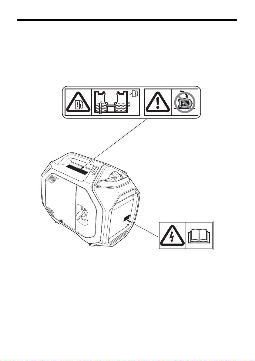
SÉCURITÉ DU GROUPE ÉLECTROGÈNE
MISE EN GARDE SUR LA
PRISE
NE PAS TROP REMPLIR NE PAS FAIRE BASCULER
12

SÉCURITÉ DU GROUPE ÉLECTROGÈNE
• Un système d’échappement chaud peut
provoquer de graves brûlures.
Ne le touchez pas si le moteur vient de tourner.
• Les groupes électrogènes Honda ont été conçus
pour assurer un fonctionnement sûr et fiable
lorsqu’ils sont utilisés conformément aux
instructions données.
Lisez et assimilez le manuel de l’utilisateur
avant d’utiliser le groupe électrogène. Le
non-respect de cette consigne peut entraîner
des blessures ou des dommages.
• Les gaz d’échappement contiennent du
monoxyde de carbone, un gaz toxique incolore
et inodore. L’inhalation de monoxyde de
carbone peut provoquer l’évanouissement et
entraîner la mort.
• Si vous faites fonctionner le groupe électrogène
dans un endroit fermé ou même partiellement
clos, l’air respiré peut contenir une quantité
dangereuse de gaz d’échappement.
• Ne faites jamais fonctionner le groupe
électrogène dans un garage, dans une maison
ou à proximité de fenêtres ou de portes
ouvertes.
• L’essence est hautement inflammable et
explosive. Arrêtez le moteur et laissez-le
refroidir avant de faire le plein.
13

SÉCURITÉ DU GROUPE ÉLECTROGÈNE
• Un raccordement incorrect au système
électrique d’un bâtiment peut permettre le
retour du courant du groupe électrogène dans le
réseau public.
Un tel retour du courant peut provoquer
l’électrocution du personnel de la compagnie
d’électricité ou de toute autre personne
touchant les lignes électriques pendant une
panne de courant. De plus, le groupe
électrogène risque d’exploser, de brûler ou de
provoquer un incendie lors du rétablissement
du courant.
Avant d’effectuer des raccordements
électriques, consultez la compagnie d’électricité
ou un électricien qualifié.
• Ne remplissez pas le réservoir au-delà du
repère de limite rouge.
Le remplissage excessif ou le basculement
du groupe électrogène peut entraîner
l’écoulement de carburant dans l’aérateur
et provoquer une fuite ou un incendie.
Vous risquez des brûlures ou des blessures
graves.
• Raccordez et retirez le boîtier de la prise pour le
fonctionnement en parallèle lorsque le moteur
est à l’arrêt.
• Pour l’utilisation d’un groupe électrogène seul,
le boîtier de la prise pour le fonctionnement en
parallèle doit être retiré.
14

SÉCURITÉ DU GROUPE ÉLECTROGÈNE
MARQUAGES CE, UKCA ET DE PUISSANCE
ACOUSTIQUE
Année de production
Nom et adresse du
fabricant
Nom et adresse du
représentant autorisé
Classe de performances
Classe de qualité
Code IP
Etiquette sur les émissions sonores
Masse à sec (poids)
• Emplacement des marquages CE, UKCA et de puissance acoustique
Le nom et l’adresse du fabricant, ainsi que du représentant autorisé sont
indiqués dans la PRESÉNTATION DU CONTENU de la « Déclaration de
conformité » du présent manuel de l’utilisateur.
15

CONSIGNES POUR LA PREMIÈRE UTILISATION
COUVERCLE DE VISITE
VIS DU COUVERCLE DE VISITE
BOUCHON DE
REMPLISSAGE
D’HUILE
LIMITE SUPÉRIEURE
(l’huile atteint le
goulot de
remplissage d’huile)
GOULOT DE
REMPLISSAGE
D’HUILE
JAUGE D’HUILE
HUILE MOTEUR
Le groupe électrogène est expédié SANS HUILE dans le moteur.
1. Placez le groupe électrogène sur une surface horizontale.
2. Desserrez la vis du couvercle de visite et retirez le couvercle de visite.
3. Une fois le groupe électrogène en position horizontale, retirez le bouchon de
remplissage d’huile en le tournant dans le sens inverse des aiguilles d’une montre.
4. Ajoutez de l’huile en quantité suffisante pour que le niveau atteigne la limite
supérieure du goulot de remplissage d’huile. La catégorie de service API
SAE10W-30 SE ou ultérieure (ou équivalente) est préconisée pour un usage
général. Pour plus de recommandations, reportez-vous à la page 17.
Contenance maximale en huile : 0,46 litre
Ne remplissez pas trop le moteur.
Si le moteur est trop rempli, l’excédent
d’huile risque d’être transféré dans le logement du filtre à air et dans le filtre à air.
5. Vissez bien le bouchon de remplissage d’huile.
6. Réinstallez le couvercle de visite et serrez bien la vis du couvercle de visite.
16

CONSIGNES POUR LA PREMIÈRE UTILISATION
TEMPÉRATURE AMBIANTE
RECOMMANDATIONS POUR L’HUILE MOTEUR
L’huile est un facteur déterminant pour les performances et la longévité du
moteur. Utilisez une huile détergente automobile 4 temps.
L’indice SAE 10W-30 est préconisé pour un usage général. Les autres viscosités
indiquées dans le tableau peuvent être utilisées lorsque la température
moyenne du lieu d’utilisation se trouve dans la plage recommandée.
Spécifications d’huile de lubrification nécessaires pour garder un système de
contrôle des émissions performant : Huile d’origine Honda.
Avant utilisation, lisez les instructions figurant sur le bidon d’huile.
La viscosité d’huile SAE et la catégorie de service API sont indiquées sur
l’étiquette API du bidon d’huile. Honda recommande l’utilisation d’une huile de
catégorie de service API SE ou ultérieure (ou une huile équivalente).
17
 Loading...