

Honda CBF600SA, CBF600N, CBF600S, CBF600NA Service Manual

TYPE CODE
Manuals by Motomatrix / www.motomatrix.co.uk / The Solution For Lost Motorcycle Coded Keys.
email: info@motomatrix.co.uk
• Throughout this manual, the following abbreviations are used to identify individual model.
CODE AREA TYPE
E U.K, Ireland
F France, Belgium
EUROPEAN DIRECT SALES
ED
III ED Germany
(Spain, Holland, Austria, Portugal, Belgium, Denmark, Greece, Italy, Macedonia,
Romania, Burgaria, Ukuraine, Israel, Finland, Germany, Sweden, Island, Russia,
Poland, Slovenia, Croatia, Latvia, Norway, Swiss, Luxemburug, Hungary, Czech,
Slovakia)
A Few Words About Safety
Improper service or repairs can create an
unsafe condition that can cause your customer
or others to be seriously hurt or killed.
Follow the procedures and precautions in this
manual and other service materials carefully.
Failure to properly follow instructions and
precautions can cause you to be seriously hurt
or killed.
Follow the procedures and precautions in this
manual carefully.
Manuals by Motomatrix / www.motomatrix.co.uk / The Solution For Lost Motorcycle Coded Keys.
email: info@motomatrix.co.uk
Service Information
The service and repair information contained in this manual is intended for use by qualified, professional technicians.
Attempting service or repairs without the proper training, tools, and equipment could cause injury to you or others. It could also
damage the vehicle or create an unsafe condition.
This manual describes the proper methods and procedures for performing service, maintenance, and repairs. Some procedures
require the use of specially designed tools and dedicated equipment. Any person who intends to use a replacement part, service
procedure or a tool that is not recommended by Honda, must determine the risks to their personal safety and the safe operation of
the vehicle.
If you need to replace a part, use genuine Honda parts with the correct part number or an equivalent part. We strongly recommend
that you do not use replacement parts of inferior quality.
For Your Customer’s Safety
Proper service and maintenance are essential to the customer’s safety and
the reliability of the vehicle. Any error or oversight while servicing a vehicle
can result in faulty operation, damage to the vehicle, or injury to others.
For Your Safety
Because this manual is intended for the professional service technician, we
do not provide warnings about many basic shop safety practices (e.g., Hot
parts–wear gloves). If you have not received shop safety training or do not
feel confident about your knowledge of safe servicing practice, we
recommended that you do not attempt to perform the procedures described
in this manual.
Some of the most important general service safety precautions are given
below. However, we cannot warn you of every conceivable hazard that can
arise in performing service and repair procedures. Only you can decide
whether or not you should perform a given task.
Important Safety Precautions
Make sure you have a clear understanding of all basic shop safety practices and that you are wearing appropriate clothing and
using safety equipment. When performing any service task, be especially careful of the following:
• Read all of the instructions before you begin, and make sure you have the tools, the replacement or repair parts, and the skills
required to perform the tasks safely and completely.
• Protect your eyes by using proper safety glasses, goggles or face shields any time you hammer, drill, grind, pry or work around
pressurized air or liquids, and springs or other stored-energy components. If there is any doubt, put on eye protection.
• Use other protective wear when necessary, for example gloves or safety shoes. Handling hot or sharp parts can cause severe
burns or cuts. Before you grab something that looks like it can hurt you, stop and put on gloves.
• Protect yourself and others whenever you have the vehicle up in the air. Any time you lift the vehicle, either with a hoist or a jack,
make sure that it is always securely supported. Use jack stands.
Make sure the engine is off before you begin any servicing procedures, unless the instruction tells you to do otherwise.
This will help eliminate several potential hazards:
• Carbon monoxide poisoning from engine exhaust. Be sure there is adequate ventilation whenever you run the engine.
• Burns from hot parts or coolant. Let the engine and exhaust system cool before working in those areas.
• Injury from moving parts. If the instruction tells you to run the engine, be sure your hands, fingers and clothing are out of the way.
Gasoline vapors and hydrogen gases from batteries are explosive. To reduce the possibility of a fire or explosion, be careful when
working around gasoline or batteries.
• Use only a nonflammable solvent, not gasoline, to clean parts.
• Never drain or store gasoline in an open container.
• Keep all cigarettes, sparks and flames away from the battery and all fuel-related parts.
HOW TO USE THIS MANUAL
Manuals by Motomatrix / www.motomatrix.co.uk / The Solution For Lost Motorcycle Coded Keys.
email: info@motomatrix.co.uk
CONTENTS
This service manual describes the service procedures for the
CBF600S/SA/N/NA.
Follow the Maintenance Schedule (Section 3) recommendations to
ensure that the vehicle is in peak operating condition.
Performing the first scheduled maintenance is very important. It
compensates for the initial wear that occurs during the break-in
period.
Sections 1, 2 and 3 apply to the whole motorcycle. Section 2
illustrates procedures for removal/installation of components that may
be required to perform service described in the following sections.
Section 4 through 21 describe parts of the motorcycle, grouped
according to location.
Find the section you want on this page, then turn to the table of
contents on the first page of the section.
Most sections start with an assembly or system illustration, service
information and troubleshooting for the section. The subsequent
pages give detailed procedure.
If you don't know the source of the trouble, go to section 23
Troubleshooting.
Your safety, and the safety of others, is very important. To help
you make informed decisions we have provided safety
messages and other information throughout this manual. Of
course, it is not practical or possible to warn you about all the
hazards associated with servicing this vehicle.
You must use your own good judgement.
You will find important safety information in a variety of forms
including:
• Safety Labels – on the vehicle
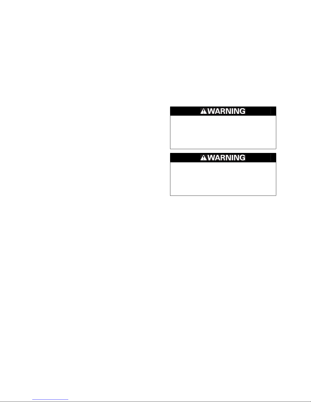
• Safety Messages – preceded by a safety alert symbol and
one of three signal words, DANGER, WARNING, or CAUTION.
These signal words mean:
• Instructions – how to service this vehicle correctly and safely.
As you read this manual, you will find information that is preceded by a
symbol. The purpose of this message is to help prevent
damage to your vehicle, other property, or the environment.
ALL INFORMATION, ILLUSTRATIONS, DIRECTIONS AND SPECIFICATIONS INCLUDED IN
THIS PUBLICATION ARE BASED ON THE
LATEST PRODUCT INFORMATION AVAILABLE AT THE TIME OF APPROVAL FOR
PRINTING.HONDAMOTORCO.,LTD.
RESERVES THE RIGHT TO MAKE CHANGES
AT ANY TIME WITHOUT NOTICE AND WITHOUT INCURRING ANY OBLIGATION WHATSOEVER. NO PART OF THIS PUBLICATION MAY
BE REPRODUCED WITHOUT WRITTEN PERMISSION. THIS MANUAL IS WRITTEN FOR
PERSONS WHO HAVE ACQUIRED BASIC
KNOWLEDGE OF MAINTENANCE ON HONDA
MOTORCYCLES, MOTOR SCOOTERS OR
ATVS.
You WILL be KILLED or SERIOUSLY
HURT if you don’t follow instructions.
You CAN be KILLED or SERIOUSLY
HURT if you don’t follow instructions.
You CAN be HURT if you don’t follow
instructions.
GENERAL INFORMATION
FRAME/BODY PANELS/EXHAUST SYSTEM
MAINTENANCE
LUBRICATION SYSTEM
FUEL SYSTEM (PGM-FI)
COOLING SYSTEM
ENGINE REMOVAL/INSTALLATION
CYLINDER HEAD/VALVES
CLUTCH/STARTER CLUTCH/
GEARSHIFT LINKAGE
ALTERNATOR
ENGINE AND DRIVE TRAIN
CRANKCASE/TRANSMISSION
CRANKSHAFT/PISTON/CYLINDER
FRONT WHEEL/SUSPENSION/
STEERING
REAR WHEEL/SUSPENSION
HYDRAULIC BRAKE
CHASSIS
ANTI-LOCK BRAKE SYSTEM
(ABS; CBF600SA/NA)
BATTERY/CHARGING SYSTEM
IGNITION SYSTEM
ELECTRIC STARTER
LIGHTS/METER/SWITCHES
ELECTRICAL
IMMOBILIZER SYSTEM (HISS)
WIRING DIAGRAMS
TROUBLESHOOTING
INDEX
1
2
3
4
5
6
7
8
9
10
11
12
13
14
15
16
17
18
19
20
21
22
23
24
SERVICE PUBLICATION OFFICE
Date of Issue: November, 2007
©honda Motor Co., Ltd.
Honda Motor Co., Ltd.

SYMBOLS
Manuals by Motomatrix / www.motomatrix.co.uk / The Solution For Lost Motorcycle Coded Keys.
email: info@motomatrix.co.uk
The symbols used throughout this manual show specific service procedures. If supplementary information is required pertaining to
these symbols, it would be explained specifically in the text without the use of the symbols.
Replace the part(s) with new one(s) before assembly.
Use recommended engine oil, unless otherwise specified.
Use molybdenum oil solution (mixture of the engine oil and molybdenum grease in a ratio of 1: 1).
Use multi-purpose grease (Lithium based multi-purpose grease NLGI #2 or equivalent).
Use molybdenum disulfide grease (containing more than 3% molybdenum disulfide, NLGI #2 or
equivalent).
Example: Molykote
Multi-purpose M-2 manufactured by Mitsubishi Oil, Japan
Use molybdenum disulfide paste (containing more than 40% molybdenum disulfide, NLGI #2 or
equivalent).
Example: Molykote®G-n Paste manufactured by Dow Corning U.S.A.
Honda Moly 60 (U.S.A. only)
Rocol ASP manufactured by Rocol Limited, U.K.
Rocol Paste manufactured by Sumico Lubricant, Japan
®
BR-2 plus manufactured by Dow Corning U.S.A.
Use silicone grease.
Apply a locking agent. Use a middle strength locking agent unless otherwise specified.
Apply sealant.
Use DOT 4 brake fluid. Use the recommended brake fluid unless otherwise specified.
Use Fork or Suspension Fluid.

1. GENERAL INFORMATION
Manuals by Motomatrix / www.motomatrix.co.uk / The Solution For Lost Motorcycle Coded Keys.
email: info@motomatrix.co.uk
1
SERVICE RULES ········································· 1-2
MODEL IDENTIFICATION··························· 1-3
GENERAL SPECIFICATIONS······················1-6
LUBRICATION SYSTEM
SPECIFICATIONS········································ 1-8
FUEL SYSTEM (PGM-FI)
SPECIFICATIONS········································ 1-8
COOLING SYSTEM SPECIFICATIONS ······ 1-8
CYLINDER HEAD/VALVES
SPECIFICATIONS········································ 1-9
CLUTCH/STARTER CLUTCH/
GEARSHIFT LINKAGE SPECIFICATIONS·· 1-9
CRANKCASE/TRANSMISSION
SPECIFICATIONS······································ 1-10
CRANKSHAFT/PISTON/CYLINDER
SPECIFICATIONS······································ 1-10
FRONT WHEEL/SUSPENSION/STEERING
SPECIFICATIONS ····································· 1-11
REAR WHEEL/SUSPENSION
SPECIFICATIONS ····································· 1-11
HYDRAULIC BRAKE SPECIFICATIONS··· 1-12
BATTERY/CHARGING SYSTEM
SPECIFICATIONS ····································· 1-12
IGNITION SYSTEM SPECIFICATIONS ···· 1-12
ELECTRIC STARTER SPECIFICATIONS ·· 1-13
LIGHTS/METERS/SWITCHES
SPECIFICATIONS ····································· 1-13
STANDARD TORQUE VALUES··············· 1-14
ENGINE & FRAME TORQUE VALUES ···· 1-14
LUBRICATION & SEAL POINTS ·············· 1-21
CABLE & HARNESS ROUTING ··············· 1-24
EMISSION CONTROL SYSTEMS ············ 1-48
1-1

GENERAL INFORMATION
Manuals by Motomatrix / www.motomatrix.co.uk / The Solution For Lost Motorcycle Coded Keys.
email: info@motomatrix.co.uk
GENERALINFORMATION
SERVICE RULES
1. Use genuine Honda or Honda-recommended parts and lubricants or their equivalents. Parts that don't meet Honda's
design specifications may cause damage to the motorcycle.
2. Use the special tools designed for this product to avoid damage and incorrect assembly.
3. Use only metric tools when servicing the motorcycle. Metric bolts, nuts and screws are not interchangeable with
English fasteners.
4. Install new gaskets, O-rings, cotter pins, and lock plates when reassembling.
5. When tightening bolts or nuts, begin with the larger diameter or inner bolt first. Then tighten to the specified torque
diagonally in incremental steps unless a particular sequence is specified.
6. Clean parts in cleaning solvent upon disassembly. Lubricate any sliding surfaces before reassembly.
7. After reassembly, check all parts for proper installation and operation.
8. Route all electrical wires as show in the Cable and Harness Routing (page 1-24).
ABBREVIATION
Throughout this manual, the following abbreviations are used to identify the respective parts or systems.
Abbrev. term Full term
ABS Anti-lock Brake System
CKP sensor Crankshaft Position sensor
DLC Data Link Connector
DTC Diagnostic Trouble Code
ECM Engine Control Module
ECT sensor Engine Coolant Temperature sensor
EEPROM Electrically Erasable Programmable Read Only Memory
EOP switch Engine Oil Pressure switch
HDS Honda Diagnostic System
HISS Honda Ignition Security System
IACV Idle Air Control Valve
IAT sensor Intake Air Temperature sensor
IDC solenoid valve Intake Duct Control solenoid valve
MAP sensor Manifold Absolute Pressure sensor
MIL Malfunction Indicator Lamp
PAIR Pulsed Secondary Air Injection
PCV Proportional Control Valve
PGM-FI Programmed Fuel Injection
SCS connector Service Check Short connector
TP sensor Throttle Position sensor
VS sensor Vehicle Speed sensor
1-2

MODEL IDENTIFICATION
Manuals by Motomatrix / www.motomatrix.co.uk / The Solution For Lost Motorcycle Coded Keys.
email: info@motomatrix.co.uk
CBF600SA shown:
GENERAL INFORMATION
CBF600N shown:
1-3
GENERAL INFORMATION
VEHICLE IDENTIFICATION NUMBER
REGISTERED NUMBER PLATE
ENGINE SERIAL NUMBER
THROTTLE BODY IDENTIFICATION NUMBER
Manuals by Motomatrix / www.motomatrix.co.uk / The Solution For Lost Motorcycle Coded Keys.
email: info@motomatrix.co.uk
SERIAL NUMBERS
The Vehicle Identification Number (V.I.N) is stamped on the right side
of the steering head.
The registered number plate is located on left side of the frame tube.
The engine serial number is stamped on the right side of the upper
crankcase.
The throttle body identification number is stamped on the throttle
body as shown.
1-4

LABEL
COLOR LABEL
Manuals by Motomatrix / www.motomatrix.co.uk / The Solution For Lost Motorcycle Coded Keys.
email: info@motomatrix.co.uk
The color label is attached to the frame under the seat. When ordering
color-coded parts, always specify the designated color code.
GENERAL INFORMATION
1-5

GENERAL INFORMATION
Manuals by Motomatrix / www.motomatrix.co.uk / The Solution For Lost Motorcycle Coded Keys.
email: info@motomatrix.co.uk
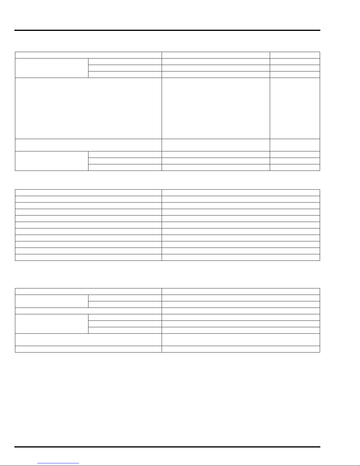
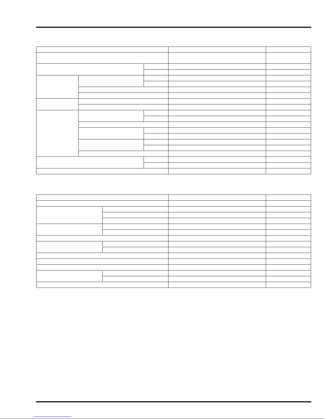
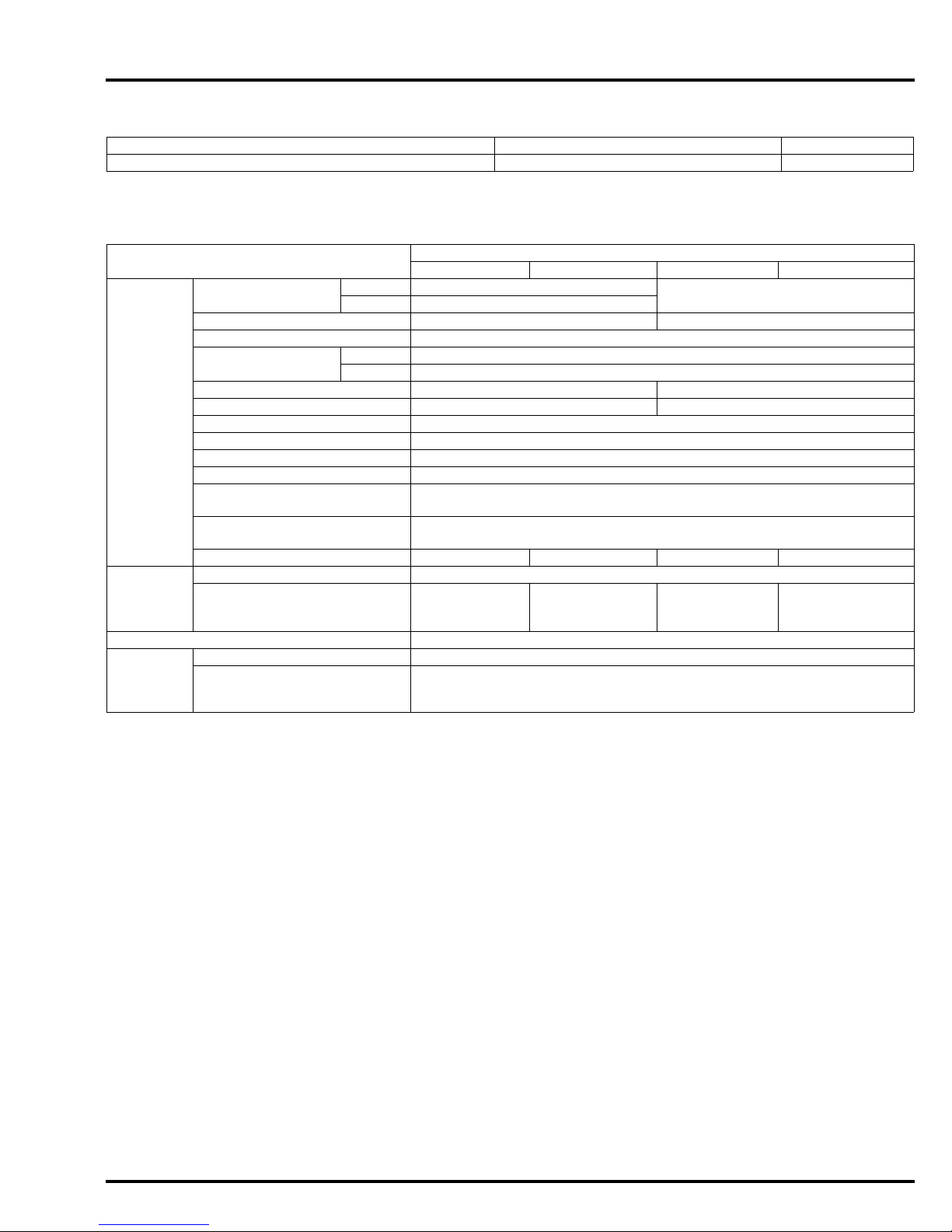
GENERAL SPECIFICATIONS
ITEM SPECIFICATIONS
DIMENSIONS Overall length 2,160 mm (85 in)
Overall width 765 mm (30 in)
Overall height CBF600S/SA Wind screen STD 1,240 mm (49 in)
Wind screen HIGH 1,285 mm (51 in)
CBF600N/NA 1,110 mm (44 in)
Wheelbase 1,490 mm (59 in)
Seat height 785 ± 15mm (31 ± 0.6in)
Footpeg height 325 mm (12.8 in)
Ground clearance 136 mm (5.4 in)
Curb weight CBF600S 217 kg (478 lbs)
CBF600SA 222 kg (489 lbs)
CBF600N 213 kg (470 lbs)
CBF600NA 218 kg (481 lbs)
Maximum weight capacity 195 kg (430 lbs)
FRAME Frame type Diamond
Front suspension Telescopic fork
Front axle travel 108 mm (4.3 in)
Rear suspension Swingarm
Rear axle travel 120 mm (4.7 in)
Front tire size 120/70 ZR 17M/C (58W)
Rear tire size 160/60 ZR 17M/C (69W)
Front tire brand BT-57F RADIAL U
Rear tire brand BT-57R RADIAL E
Front brake Hydraulic double disc
Rear brake Hydraulic single disc
Caster angle 26° 00’
Trail length 110 mm (4.3 in)
Fuel tank capacity 20 liter
Fuel reserve capacity 4.0 liter
ENGINE Cylinder arrangement 4 cylinders in-line, inclined 30°
Bore and stroke 67.0 X 42.5 mm (2.64 X 1.67 in)
Displacement 599 cm
Compression ratio 11.6: 1
Valve train Chain driven, DOHC
FUEL
DELIVERY
SYSTEM
Intake valve opens at 1 mm (0.04 in)
closes at 1 mm (0.04 in)
Exhaust valve opens at 1 mm (0.04 in)
closes at 1 mm (0.04 in)
Lubrication system Forced pressure and wet sump
Oil pump type Trochoid
Cooling system Liquid cooled
Air filtration Paper element
Engine dry weight 57.3 kg (126.4 lbs)
Firing order 1 - 2 - 4 - 3
Type PGM-FI
Throttle bore 32 mm (1.3 in)
lift
lift
lift
lift
(Bridgestone)
PILOT ROAD B (Michelin)
(Bridgestone)
PILOT ROAD A (Michelin)
(5.28 US gal, 4.40 lmp gal)
(1.06 US gal, 0.88 lmp gal)
from vertical
3
(36.5 cu-in)
15° BTDC
15° ABDC
30° BBDC
0° ATDC
(Programmed Fuel Injection)
1-6

GENERAL INFORMATION
Manuals by Motomatrix / www.motomatrix.co.uk / The Solution For Lost Motorcycle Coded Keys.
email: info@motomatrix.co.uk
ITEM SPECIFICATIONS
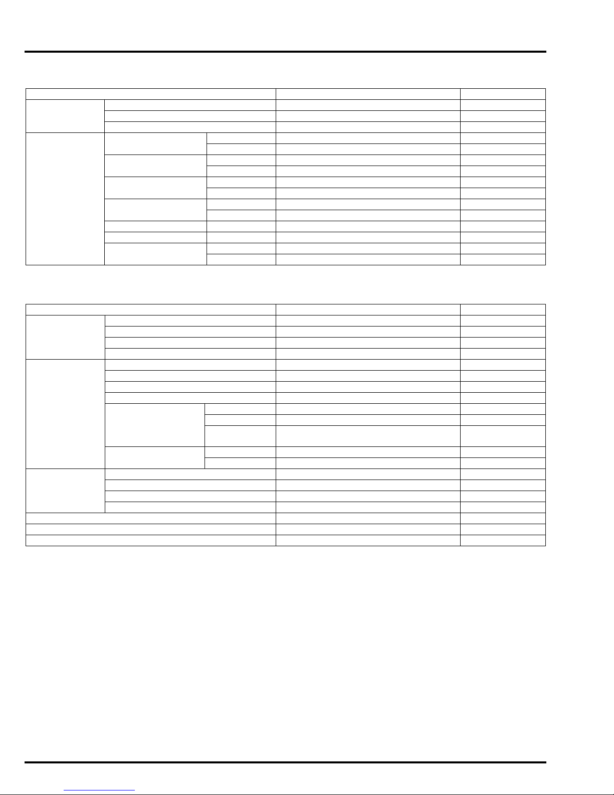
DRIVE TRAIN Clutch system Multi-plate, wet
Clutch operation system Cable operating
Transmission Constant mesh, 6-speeds
Primary reduction 2.111 (76/36)
Final reduction 2.625 (42/16)
Gear ratio 1st 2.750 (33/12)
2nd 1.938 (31/16)
3rd 1.556 (28/18)
4th 1.304 (30/23)
5th 1.150 (23/20)
6th 1.041 (25/24)
Gearshift pattern 1 - N - 2 - 3 - 4 - 5 - 6
ELECTRICAL Ignition system Computer-controlled digital
transistorized with electric
advance
Starting system Electric starter motor
Charging system Triple phase output alternator
Regulator/rectifier SCR shorted/triple phase, full
Lighting system Battery
wave rectification
1-7
GENERAL INFORMATION
Manuals by Motomatrix / www.motomatrix.co.uk / The Solution For Lost Motorcycle Coded Keys.
email: info@motomatrix.co.uk
LUBRICATION SYSTEM SPECIFICATIONS
Unit: mm (in)
ITEM STANDARD SERVICE LIMIT
Engine oil capacity After draining 2.7 liter (2.9 US qt, 2.4 lmp qt) –
After oil filter change 2.8 liter (3.0 US qt, 2.5 lmp qt) –
After disassembly 3.5 liter (3.7 US qt, 3.1 lmp qt) –
Engine oil Suggested oil: –
Honda "4-stroke motorcycle oil" or
an equivalent
Oil recommendation:
API classification: SG or higher
(except oils labeled as energy conserving on the circular API service
label)
Viscosity: SAE 10W-30
JASO T 903 standard: MA
Oil pressure at EOP switch 496 kPa (5.1 kgf/cm
6,000 min
Oil pump Tip clearance 0.15 (0.006) 0.20 (0.008)
Body clearance 0.15 – 0.21 (0.006 – 0.008) 0.35 (0.014)
Side clearance 0.04 – 0.09 (0.002 – 0.004) 0.17 (0.007)
-1
(rpm)/(80°C/176°F)
2
, 72 psi) at
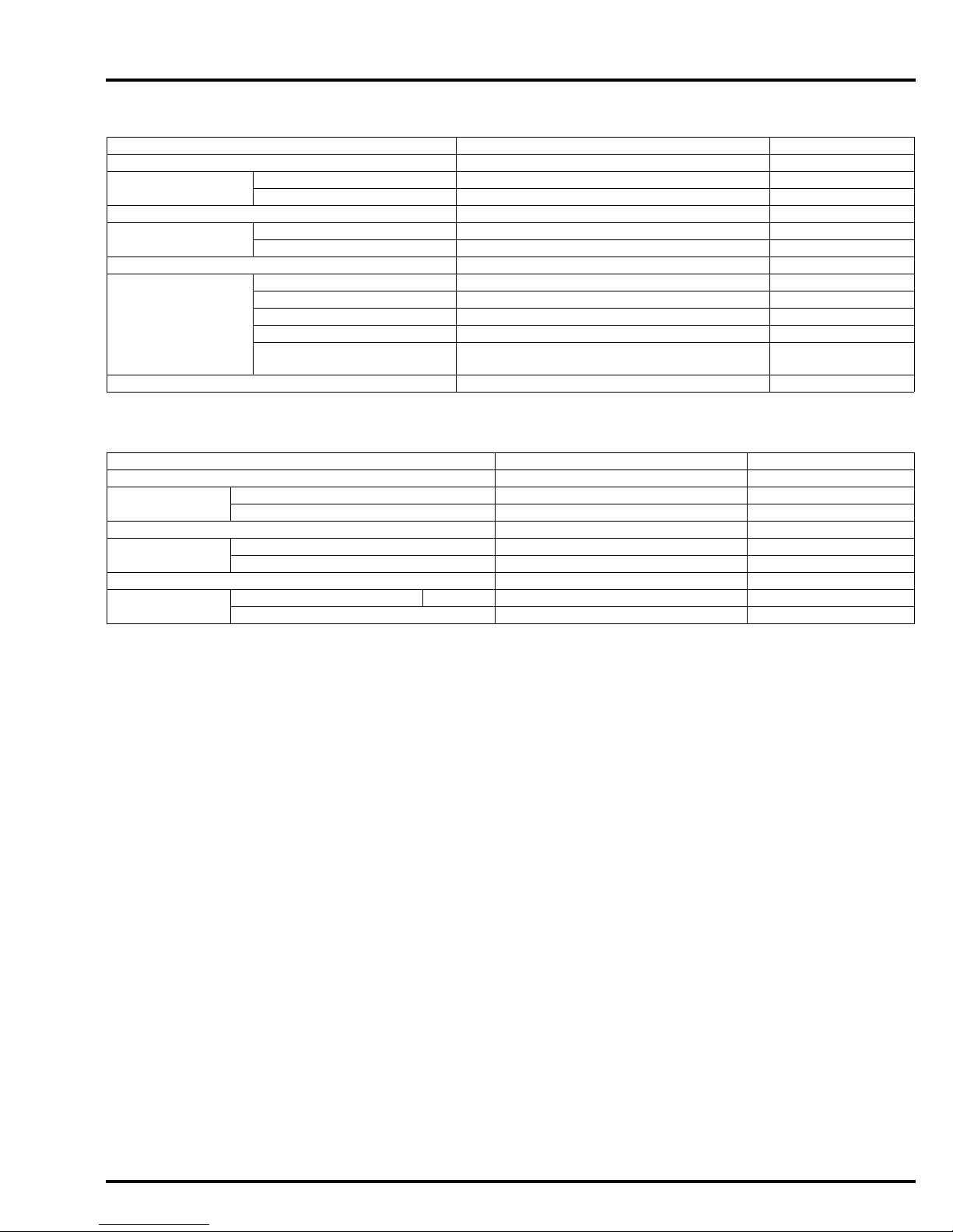
FUEL SYSTEM (PGM-FI) SPECIFICATIONS
ITEM SPECIFICATIONS
Throttle body identification number GQ84A
Idle speed 1,300 ± 100 min
Throttle grip freeplay 2 – 6 mm (1/16 – 1/4 in)
IAT sensor resistance (at 20°C/68°F) 1 – 4 kΩ
ECT sensor resistance (at 20°C/68°F) 2.3 – 2.6 kΩ
Fuel injector resistance (at 20°C /68°F) 11 – 13 Ω
PAIR control solenoid valve resistance (at 20°C/68°F) 23 – 27 Ω
CKP sensor peak voltage (at 20°C/68°F) 0.7 V minimum
Fuel pressure at idle 343 kPa (3.5 kgf/cm
Fuel pump flow (at 12 V) 189 cm
3
(6.4 US oz, 6.7 lmp oz) minimum/10 seconds
-1
(rpm)
2
, 50 psi)
–
COOLING SYSTEM SPECIFICATIONS
ITEM SPECIFICATIONS
Coolant capacity Radiator and engine 2.42 liter (2.56 US qt, 2.13 lmp qt)
Reserve tank 0.35 liter (0.37 US qt, 0.31 lmp qt)
Radiator cap relief pressure 108 – 137 kPa (1.1 – 1.4 kgf/cm
Thermostat Begin to open 80 – 84 °C (176 – 183 °F)
Fully open 95 °C (203 °F)
Valve lift 8 mm (0.3 in) minimum
Recommended antifreeze High quality ethylene glycol antifreeze containing corrosion
protection inhibitors
Standard coolant concentration 1:1 mixture with distilled water
2
, 16 – 20 psi)
1-8
GENERAL INFORMATION
Manuals by Motomatrix / www.motomatrix.co.uk / The Solution For Lost Motorcycle Coded Keys.
email: info@motomatrix.co.uk
CYLINDER HEAD/VALVES SPECIFICATIONS
Unit: mm (in)
ITEM STANDARD SERVICE LIMIT
Cylinder compression 1,304 kPa (13.3 kgf/cm
Valve clearance IN 0.20 ± 0.03 (0.008 ± 0.001) –
EX 0.28 ± 0.03 (0.011 ± 0.001) –
Camshaft Cam lobe height IN 34.38 – 34.62 (1.354 – 1.363) 34.36 (1.353)
EX 33.86 – 34.10 (1.333 – 1.343) 33.84 (1.332)
Runout – 0.05 (0.002)
Oil clearance 0.020 – 0.062 (0.0008 – 0.0024) 0.10 (0.004)
Valve lifter Valve lifter O.D. 25.978 – 25.993 (1.0228 – 1.0233) 25.97 (1.022)
Valve lifter bore I.D. 26.010 – 26.026 (1.0240 – 1.0246) 26.04 (1.025)
Valve,
valve guide
Valve spring free length IN 40.19 (1.582) 39.4 (1.55)
Cylinder head warpage – 0.10 (0.004)
Valve stem O.D. IN 3.975 – 3.990 (0.1565 – 0.1571) 3.965 (0.1561)
EX 3.965 – 3.980 (0.1561 – 0.1567) 3.955 (0.1557)
Valve guide I.D. 4.000 – 4.012 (0.1575 – 0.1580) 4.04 (0.159)
Stem-to-guide clearance IN 0.010 – 0.037 (0.0004 – 0.0015) 0.075 (0.0030)
EX 0.020 – 0.047 (0.0008 – 0.0019) 0.085 (0.0033)
Valve guide projection
above cylinder head
Valve seat width 0.90 – 1.10 (0.035 – 0.043) 1.5 (0.06)
IN 17.1 – 17.4 (0.67 – 0.69) –
EX 13.3 – 13.6 (0.52 – 0.54) –
EX 39.76 (1.565) 39.0 (1.54)
at 350 min
-1
(rpm)
2
, 189 psi)
–
CLUTCH/STARTER CLUTCH/GEARSHIFT LINKAGE SPECIFICATIONS
Unit: mm (in)
ITEM STANDARD SERVICE LIMIT
Clutch lever freeplay 10 – 20 (3/8 – 13/16) –
Clutch Spring free length 48.2 (1.90) 47.2 (1.86)
Disc thickness 2.92 – 3.08 (0.115 – 0.121) 2.6 (0.10)
Plate warpage – 0.30 (0.012)
Clutch outer guide I.D. 24.993 – 25.003 (0.9840 – 0.9844) 25.013 (0.9848)
O.D. 34.996 – 35.004 (1.3778 – 1.3781) 34.986 (1.3774)
Primary driven gear I.D. 41.000 – 41.016 (1.6142 – 1.6148) 41.026 (1.6152)
Oil pump drive sprocket
guide
Oil pump drive sprocket I.D. 35.025 – 35.145 (1.3789 – 1.3837) 35.155 (1.3841)
Mainshaft O.D. at clutch outer guide 24.980 – 24.990 (0.9835 – 0.9839) 24.960 (0.9827)
Mainshaft O.D. at oil pump drive sprocket guide 24.980 – 24.990 (0.9835 – 0.9839) 24.960 (0.9827)
Starter idle gear Gear I.D. 10.013 – 10.035 (0.3942 – 0.3951) 10.05 (0.396)
Starter driven gear boss O.D. 45.657 – 45.673 (1.7975 – 1.7981) 45.642 (1.7969)
I.D. 25.000 – 25.021 (0.9843 – 0.9851) 25.031 (0.9855)
O.D. 34.950 – 34.975 (1.3760 – 1.3770) 34.940 (1.3756)
Shaft O.D. 9.991 – 10.000 (0.3933 – 0.3937) 9.98 (0.393)
1-9
GENERAL INFORMATION
Manuals by Motomatrix / www.motomatrix.co.uk / The Solution For Lost Motorcycle Coded Keys.
email: info@motomatrix.co.uk
CRANKCASE/TRANSMISSION SPECIFICATIONS
Unit: mm (in)
ITEM STANDARD SERVICE LIMIT
Shift fork,
fork shaft
Transmission Gear I.D. M5,M6 28.000 – 28.021 (1.1024 – 1.1032) 28.04 (1.104)
I.D. 12.000 – 12.021 (0.4724 – 0.4733) 12.03 (0.474)
Claw thickness 5.93 – 6.00 (0.233 – 0.236) 5.9 (0.23)
Shift fork shaft O.D. 11.957 – 11.968 (0.4707 – 0.4712) 11.95 (0.470)
C2, C3, C4 31.000 – 31.025 (1.2205 – 1.2215) 31.04 (1.222)
Gear busing O.D. M5, M6 27.959 – 27.980 (1.1007 – 1.1016) 27.94 (1.100)
C2, C3, C4 30.950 – 30.975 (1.2189 – 1.2197) 30.94 (1.218)
Gear-to-bushing
clearance
Gear bushing I.D. M5 24.985 – 25.006 (0.9837 – 0.9845) 25.016 (0.9849)
Mainshaft O.D. at M5 24.967 – 24.980 (0.9830 – 0.9835) 24.96 (0.983)
Countershaft O.D. at C2 27.967 – 27.980 (1.1011 – 1.1016) 27.96 (1.101)
Bushing to shaft
clearance
M5, M6 0.020 – 0.062 (0.0008 – 0.0024) 0.10 (0.004)
C2, C3, C4 0.025 – 0.075 (0.0010 – 0.0030) 0.11 (0.004)
C2 27.985 – 28.006 (1.1018 – 1.1026) 28.021 (1.1032)
M5 0.005 – 0.039 (0.0002 – 0.0015) 0.06 (0.002)
C2 0.005 – 0.039 (0.0002 – 0.0015) 0.06 (0.002)
CRANKSHAFT/PISTON/CYLINDER SPECIFICATIONS
Unit: mm (in)
ITEM STANDARD SERVICE LIMIT
Crankshaft Connecting rod side clearance 0.15 – 0.30 (0.006 – 0.012) 0.35 (0.014)
Crankpin bearing oil clearance 0.028 – 0.052 (0.0011 – 0.0020) 0.06 (0.002)
Main journal bearing oil clearance 0.020 – 0.038 (0.0008 – 0.0015) 0.05 (0.002)
Runout – 0.05 (0.002)
Piston, piston
rings
Cylinder I.D. 67.000 – 67.015 (2.6378 – 2.6384) 67.10 (2.642)
Cylinder-to-piston clearance 0.015 – 0.050 (0.0006 – 0.0022) 0.10 (0.004)
Connecting rod small end I.D. 16.030 – 16.044 (0.6311 – 0.6317) 16.05 (0.632)
Connecting rod-to-piston pin clearance 0.030 – 0.050 (0.0012 – 0.0020) 0.07 (0.003)
Piston O.D. at 6 (0.2) from bottom 66.965 – 66.985 (2.6364 – 2.6372) 66.90 (2.634)
Piston pin bore I.D. 16.002 – 16.008 (0.6300 – 0.6302) 16.02 (0.631)
Piston pin O.D. 15.994 – 16.000 (0.6297 – 0.6299) 15.98 (0.629)
Piston-to-piston pin clearance 0.002 – 0.014 (0.0001 – 0.0006) 0.04 (0.002)
Piston ring end
gap
Piston ring-to-ring
groove clearance
Out of round – 0.10 (0.004)
Taper – 0.10 (0.004)
Warpage – 0.10 (0.004)
Top 0.10 – 0.20 (0.004 – 0.008) 0.4 (0.02)
Second 0.21 – 0.31 (0.008 – 0.012) 0.5 (0.02)
Oil
(side rail)
Top 0.030 – 0.060 (0.0012 – 0.0024) 0.10 (0.004)
Second 0.015 – 0.050 (0.0006 – 0.0020) 0.08 (0.003)
0.2 – 0.7 (0.01 – 0.03) 1.0 (0.04)
1-10
GENERAL INFORMATION
Manuals by Motomatrix / www.motomatrix.co.uk / The Solution For Lost Motorcycle Coded Keys.
email: info@motomatrix.co.uk
FRONT WHEEL/SUSPENSION/STEERING SPECIFICATIONS
Unit: mm (in)
ITEM STANDARD SERVICE LIMIT
Minimum tire tread depth – 1.5 (0.06)
Cold tire pres-
sure
Axle runout – 0.2 (0.01)
Wheel rim runout Radial – 2.0 (0.08)
Wheel balance weight – 60 g (2.1oz) max.
Fork Spring free length 328.5 (12.93) 321.9 (12.67)
Steering head bearing pre-load 8.8 – 13.7 N (0.9 – 1.4 kgf, 2.0 – 3.1 lbf) –
Driver only 250 kPa (2.50 kgf/cm
Driver and passenger 250 kPa (2.50 kgf/cm
Axial – 2.0 (0.08)
Tube runout – 0.20 (0.008)
Recommended fork fluid Honda Ultra Cushion Oil 10W or equivalent –
Fluid level 149 (5.9) –
Fluid capacity 457 ± 2.5 cm
(15.5 ± 0.08 US oz, 16.1 ± 0.09 lmp oz)
3
2
, 36 psi) –
2
, 36 psi) –
–
REAR WHEEL/SUSPENSION SPECIFICATIONS
Unit: mm (in)
ITEM STANDARD SERVICE LIMIT
Minimum tire tread depth – 2.0 (0.08)
Cold tire pres-
sure
Axle runout – 0.2 (0.01)
Wheel rim
runout
Wheel balance weight – 60 g (2.1 oz) max.
Drive chain Size/link DID 525VM2-124LE –
Driver only 290 kPa (2.90 kgf/cm
Driver and passenger 290 kPa (2.90 kgf/cm
Radial – 2.0 (0.08)
Axial – 2.0 (0.08)
Slack 20 – 30 (0.8 – 1.2) 50 (2.0)
2
, 42 psi) –
2
, 42 psi) –
1-11
GENERAL INFORMATION
Manuals by Motomatrix / www.motomatrix.co.uk / The Solution For Lost Motorcycle Coded Keys.
email: info@motomatrix.co.uk
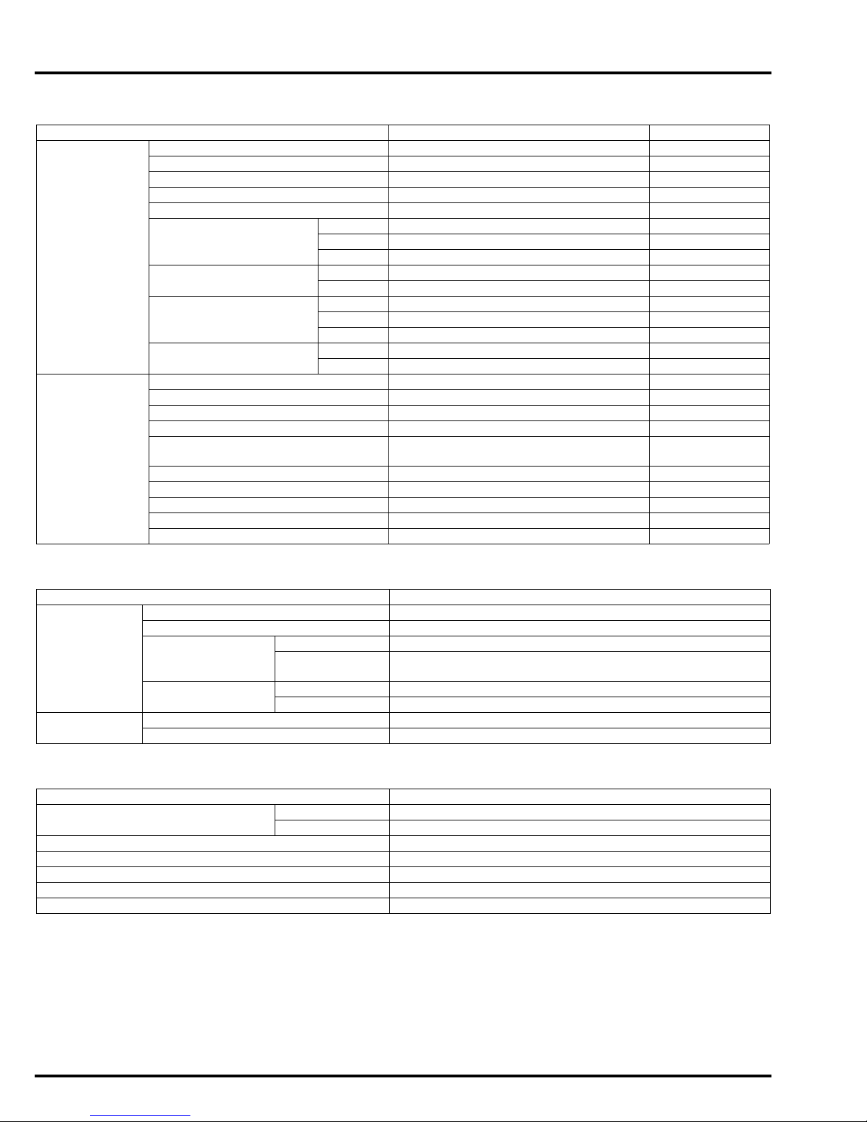
HYDRAULIC BRAKE SPECIFICATIONS
ITEM STANDARD SERVICE LIMIT
Front Specified brake fluid DOT 4 –
Brake disc thickness 4.5 (0.18) 3.5 (0.14)
Brake disc runout – 0.30 (0.012)
Master cylinder I.D. 12.700 – 12.743 (0.5000 – 0.5017) 12.755 (0.5022)
Master piston O.D. 12.657 – 12.684 (0.4983 – 0.4994) 12.645 (0.4978)
Caliper cylinder I.D.
(CBF600SA/NA)
Caliper cylinder I.D.
(CBF600S/N)
Caliper piston O.D.
(CBF600SA/NA)
Caliper piston O.D.
(CBF600S/N)
Rear Specified brake fluid DOT 4 –
Brake pedal height 67.5 (2.66) –
Brake disk thickness 5.0 (0.20) 4.0 (0.16)
Brake disc runout. – 0.30 (0.012)
Master cylinder I.D.
(CBF600SA/NA)
Master cylinder I.D. (CBF600S/N) 14.000 – 14.043 (0.5512 – 0.5529) 14.055 (0.5533)
Master piston O.D. (CBF600SA/NA) 15.827 – 15.854 (0.6231 – 0.6242) 15.815 (0.6226)
Master piston O.D. (CBF600S/N) 13.954 – 13.984 (0.5494 – 0.5510) 13.945 (0.5490)
Caliper cylinder I.D. 38.180 – 38.230 (1.5031– 1.5051 ) 38.240 (1.5055)
Caliper cylinder O.D. 38.098 – 38.148 (1.4999– 1.5019 ) 38.090 (1.4996)
Upper 22.650 – 22.700 (0.8917 – 0.8937) 22.712 (0.8942)
Middle 22.650 – 22.700 (0.8917 – 0.8937) 22.712 (0.8942)
Lower 22.650 – 22.700 (0.8917 – 0.8937) 22.712 (0.8942)
Upper 25.400 – 25.450 (1.0000 – 1.0020) 25.460 (1.0023)
Lower 25.400 – 25.450 (1.0000 – 1.0020) 25.460 (1.0023)
Upper 22.585 – 22.618 (0.8892 – 0.8905) 22.560 (0.8882)
Middle 22.585 – 22.618 (0.8892 – 0.8905) 22.560 (0.8882)
Lower 22.585 – 22.618 (0.8892 – 0.8905) 22.560 (0.8882)
Upper 25.318 – 25.368 (0.9968 – 0.9987) 25.310 (0.9965)
Lower 25.318 – 25.368 (0.9968 – 0.9987) 25.310 (0.9965)
15.870 – 15.913 (0.6248 – 0.6265) 15.925 (0.6270)
Unit: mm (in)
BATTERY/CHARGING SYSTEM SPECIFICATIONS
ITEM SPECIFICATIONS
Battery Capacity 12V – 8.6 Ah
Current leakage 2.0 mA max.
Voltage
(20°C/68°F)
Charging current Normal 0.8 A/5 – 10 h
Alternator Capacity 0.333 kW/5,000 min
Charging coil resistance (20°C/68°F) 0.1 – 1.0 Ω
Fully charged 13.0 – 13.2 V
Needs
charging
Quick 4.5 A/1.0 h
Below 12.3 V
-1
(rpm)
IGNITION SYSTEM SPECIFICATIONS
ITEM SPECIFICATIONS
Spark plug NGK CR8EH-9
DENSO U24FER9
Spark plug gap 0.80 – 0.90 mm (0.031 – 0.035 in)
Ignition coil peak voltage 100 V minimum
Ignition pulse generator peak voltage 0.7 V minimum
Ignition timing ("F"mark) 4° BTDC at idle
Idle speed 1,300 ± 100 min
-1
(rpm)
1-12
GENERAL INFORMATION
Manuals by Motomatrix / www.motomatrix.co.uk / The Solution For Lost Motorcycle Coded Keys.
email: info@motomatrix.co.uk
ELECTRIC STARTER SPECIFICATIONS
ITEM STANDARD SERVICE LIMIT
Starter motor brush length 12.0 (0.47) 6.5 (0.26)
LIGHTS/METERS/SWITCHES SPECIFICATIONS
Unit: mm (in)
ITEM
Bulbs Headlight Hi 12V – 55 W 12V – 60/55 W
Lo 12V – 55 W
Position light 12V – 5 W X 2 12V – 5 W
Brake/tail light 12V – 21/5 W
Turn signal light Front 12V – 21 W X 2
Rear 12V – 21 W X 2
Instrument light LED 12V – 1.7 W X 2
Turn signal indicator LED 12V – 1.7 W X 2
High beam indicator LED
Neutral indicator LED
Low oil pressure indicator LED
MIL LED
Coolant temperature
indicator
Immobilizer system (HISS)
indicator
ABS indicator – LED – LED
Fuse Main fuse 30 A
Sub fuse 20 A X 3
Tachometer peak voltage 10.5 V minimum
ECT
sensor
resistance
80 °C (176 °F) 2.1 – 2.6 kΩ
120 °C (248 °F) 0.65 – 0.73 kΩ
CBF600S CBF600SA CBF600N CBF600NA
30 A X 2,
10 A X 4
20 A X 3,
10 A X 5
SPECIFICATIONS
LED
LED
20 A X 3
10 A X 4
30 A X 2
20 A X 3
10 A X 5
1-13
GENERAL INFORMATION
Manuals by Motomatrix / www.motomatrix.co.uk / The Solution For Lost Motorcycle Coded Keys.
email: info@motomatrix.co.uk
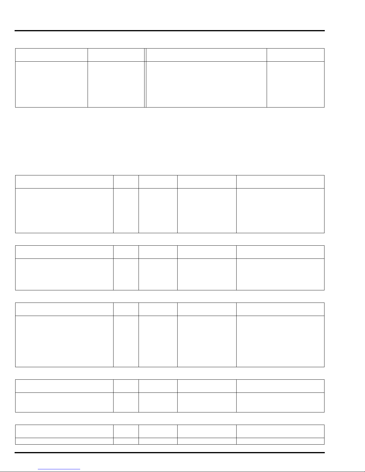
STANDARD TORQUE VALUES
FASTENER TYPE
5 mm hex bolt and nut 5.2 (0.5, 3.8) 5 mm screw 4.2 (0.4, 3.1)
6 mm hex bolt and nut 10 (1.0, 7) 6 mm screw 9.0 (0.9, 6.6)
8 mm hex bolt and nut 22 (2.2, 16) 6 mm flange bolt (8 mm head, small flange) 10 (1.0, 7)
10 mm hex bolt and nut 34 (3.5, 25) 6 mm flange bolt (8 mm head, large flange) 12 (1.2, 9)
12 mm hex bolt and nut 54 (5.5, 40) 6 mm flange bolt (10 mm head) and nut 12 (1.2, 9)
TORQUE
N·m (kgf·m, lbf·ft) N·m (kgf·m, lbf·ft)
8 mm flange bolt and nut 27 (2.8, 20)
10 mm flange bolt and nut 39 (4.0, 29)
FASTENER TYPE
TORQUE
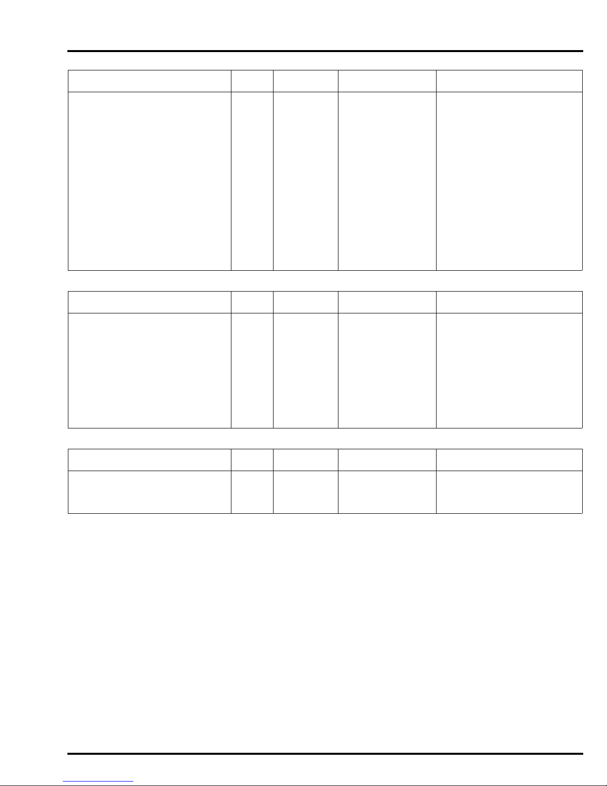
ENGINE & FRAME TORQUE VALUES
• Torque specifications listed below are for important fasteners.
• Others should be tightened to standard torque values listed above.
ENGINE
MAINTENANCE
ITEM Q'TY
Spark plug 4 10 16 (1.6, 12)
Timing hole cap 1 45 18 (1.8, 13) Apply grease to the threads.
Engine oil filter cartridge 1 20 26 (2.7, 19) Apply engine oil to the
Oil filter boss 1 20 See page 3-14 Apply a locking agent to the
Engine oil drain bolt 1 12 30 (3.1, 22)
THREAD TORQUE
DIA. (mm) N·m (kgf·m, lbf·ft)
REMARKS
threads and O-ring.
threads.
LUBRICATION SYSTEM
ITEM Q'TY
Oil pump assembly bolt 3 6 12 (1.2, 9) CT bolt
Oil pump driven sprocket bolt 1 6 15 (1.5, 11) Apply a locking agent to the
Oil pipe A mounting bolt 2 6 12 (1.2, 9) Apply a locking agent to the
FUEL SYSTEM (PGM-FI)
ITEM Q'TY
ECT sensor 1 12 23 (2.3, 17)
Insulator band screw (Throttle
body side)
Insulator band screw (Cylinder
head side)
Fuel rail mounting bolt 4 6 5.1 (0.5, 3.8)
IACV setting plate screw 2 4 2.1 (0.2, 1.5)
IACV joint screw 1 4 2.1 (0.2, 1.5)
COOLING SYSTEM
ITEM Q'TY
Water pump assembly bolt 2 6 12 (1.2, 9) CT bolt
Water pump impeller bolt 1 6 12 (1.2, 9)
Thermostat housing cover bolt 2 6 12 (1.2, 9) CT bolt
4 5 See page 5-84
4 5 See page 5-75
THREAD TORQUE
DIA. (mm) N·m (kgf·m, lbf·ft)
THREAD TORQUE
DIA. (mm) N·m (kgf·m, lbf·ft)
THREAD TORQUE
DIA. (mm) N·m (kgf·m, lbf·ft)
REMARKS
threads.
threads.
REMARKS
REMARKS
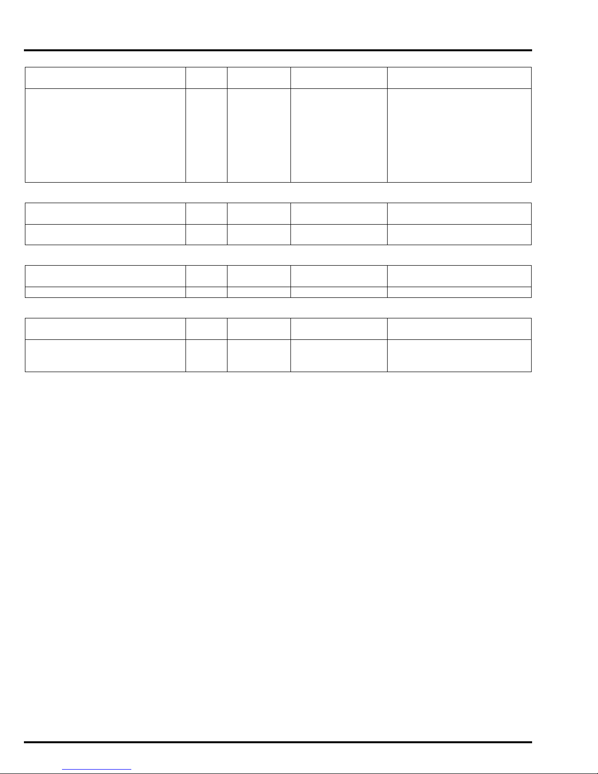
ENGINE REMOVAL/INSTALLATION
ITEM Q'TY
Drive sprocket bolt 1 10 54 (5.5, 40)
THREAD TORQUE
DIA. (mm) N·m (kgf·m, lbf·ft)
REMARKS
1-14
GENERAL INFORMATION
Manuals by Motomatrix / www.motomatrix.co.uk / The Solution For Lost Motorcycle Coded Keys.
email: info@motomatrix.co.uk
CYLINDER HEAD/VALVES
ITEM Q'TY
Cylinder head mounting bolt 10 9 47 (4.8, 35) Apply molybdenum oil solu-
Camshaft holder flange bolt 20 6 12 (1.2, 9) Apply engine oil to the
Cylinder head cover bolt 4 6 10 (1.0, 7)
PAIR check valve cover bolt 4 6 12 (1.2, 9) CT bolt
Cam sprocket bolt 4 7 20 (2.0, 15) Apply a locking agent to the
Cam chain tensioner A pivot bolt 1 6 12 (1.2, 9) Apply a locking agent to the
Cam chain tensioner B pivot bolt 1 10 20 (2.0, 15) Apply a locking agent to the
Cam chain guide A bolt 1 6 12 (1.2, 9)
Bleeding joint 1 8 12 (1.2, 9) Apply a locking agent to the
Exhaust pipe stud bolt 8 8 See page 2-11
CLUTCH/STARTER CLUTCH/GEARSHIFT LINKAGE
ITEM Q'TY
Clutch center lock nut 1 22 128 (13.1, 94) Apply engine oil to the
Clutch spring bolt 5 6 12 (1.2, 9)
Starter clutch outer mounting bolt 1 10 83 (8.5, 61) Apply engine oil to the
Shift drum center socket bolt 1 8 23 (2.3, 17) Apply a locking agent to the
Shift drum stopper arm pivot bolt 1 6 12 (1.2, 9) Apply a locking agent to the
Gearshift spindle return spring pin 1 8 22 (2.2, 16)
THREAD TORQUE
DIA. (mm) N·m (kgf·m, lbf·ft)
THREAD TORQUE
DIA. (mm) N·m (kgf·m, lbf·ft)
REMARKS
tion to the threads and seating
surface.
threads and seating surface.
threads.
threads.
threads.
threads.
REMARKS
threads and seating surface.
Stake.
threads and seating surface.
threads.
threads.
ALTERNATOR
ITEM Q'TY
Stator wire clamp flange bolt 1 6 12 (1.2, 9) CT bolt
Flywheel flange bolt 1 10 113 (11.5, 83) Apply engine oil to the
Stator mounting socket bolt 4 6 12 (1.2, 9)
THREAD TORQUE
DIA. (mm) N·m (kgf·m, lbf·ft)
REMARKS
threads and seating surface.
1-15
GENERAL INFORMATION
Manuals by Motomatrix / www.motomatrix.co.uk / The Solution For Lost Motorcycle Coded Keys.
email: info@motomatrix.co.uk
CRANKCASE/TRANSMISSION
ITEM Q'TY
Mainshaft bearing set plate bolt 3 6 12 (1.2, 9) Apply a locking agent to the
Shift drum bearing set bolt 2 6 12 (1.2, 9) Apply a locking agent to the
Crankcase 6 mm bolt 15 6 12 (1.2, 9)
8 mm bolt 1 8 24 (2.4, 18)
8 mm bolt
(main journal)
10 mm bolt 1 10 39 (4.0, 29)
CRANKSHAFT/PISTON/CYLINDER
ITEM Q'TY
Connecting rod bearing cap nut 8 7 26 (2.7, 19) Apply engine oil to the
ELECTRIC STARTER
ITEM Q'TY
Starter motor terminal nut 1 6 10 (1.0, 7)
LIGHTS/METERS/SWITCHES
ITEM Q'TY
EOP switch 1 PT 1/8 12 (1.2, 9) Apply sealant to the threads.
EOP switch wire terminal bolt 1 4 2.0 (0.2, 1.5)
Neutral switch 1 10 12 (1.2, 9)
10 8 15 (1.5, 11) + 120° See page 11-17
THREAD TORQUE
DIA. (mm) N·m (kgf·m, lbf·ft)
THREAD TORQUE
DIA. (mm) N·m (kgf·m, lbf·ft)
THREAD TORQUE
DIA. (mm) N·m (kgf·m, lbf·ft)
THREAD TORQUE
DIA. (mm) N·m (kgf·m, lbf·ft)
REMARKS
threads.
threads.
Replace with a new one.
REMARKS
threads and seating surface.
REMARKS
REMARKS
1-16
GENERAL INFORMATION
Manuals by Motomatrix / www.motomatrix.co.uk / The Solution For Lost Motorcycle Coded Keys.
email: info@motomatrix.co.uk
FRAME
FRAME/BODY PANELS/EXHAUST SYSTEM
ITEM Q'TY
Exhaust pipe joint nut 8 7 12 (1.2, 9)
Muffler mounting nut 1 8 22 (2.2, 16)
Exhaust pipe mounting nut 1 8 22 (2.2, 16)
Muffler band bolt 1 8 22 (2.2, 16)
Grab rail mounting socket bolt 4 8 27 (2.8, 20)
Front fender mounting bolt 2 6 12 (1.2, 9)
Rear view mirror mounting bolt 4 6 14 (1.4, 10) S, SA only
Side cover socket bolt 4 4 4 (0.4, 3.0)
Mainstand pivot nut 1 10 29 (3.0, 21)
Mainstand spring hook bolt 1 8 21.5 (22, 16)
FUEL SYSTEM (PGM-FI)
ITEM Q'TY
Fuel tank rear mounting nut 1 6 12 (1.2, 9)
Fuel filler cap mounting bolt 3 4 1.8 (0.2, 1.3)
Fuel pump mounting nut 7 6 12 (1.2, 9) See page 5-57
Air cleaner housing screw 9 6 3.5 (0.4, 2.6)
COOLING SYSTEM
ITEM Q'TY
Radiator upper mounting bolt 2 6 3.5 (0.4, 2.6)
Fan motor mounting bolt 3 5 5.0 (0.5, 3.7)
Fan motor shroud mounting bolt 4 6 8.4 (0.9, 6.2)
THREAD TORQUE
DIA. (mm) N·m (kgf·m, lbf·ft)
THREAD TORQUE
DIA. (mm) N·m (kgf·m, lbf·ft)
THREAD TORQUE
DIA. (mm) N·m (kgf·m, lbf·ft)
REMARKS
REMARKS
REMARKS
ENGINE REMOVAL/INSTALLATION
ITEM Q'TY
Front engine hanger nut 4 10 49 (5.0, 36)
Front engine mounting bolt 2 12 59 (6.0, 44)
Rear engine hanger nut 2 10 49 (5.0, 36)
Rear engine mounting nut 2 12 59 (6.0, 44)
Swingarm pivot bracket nut 2 10 69 (7.0, 51)
THREAD TORQUE
DIA. (mm) N·m (kgf·m, lbf·ft)
REMARKS
1-17
GENERAL INFORMATION
Manuals by Motomatrix / www.motomatrix.co.uk / The Solution For Lost Motorcycle Coded Keys.
email: info@motomatrix.co.uk
FRONT WHEEL/SUSPENSION/STEERING
ITEM Q'TY
Handlebar holder bolt 4 8 27 (2.8, 20)
Clutch lever pivot bolt 1 6 1.0 (0.1, 0.7)
Clutch lever pivot nut 1 6 6.0 (0.6, 4.4)
Clutch holder bolt 1 6 10 (1.0, 7)
Steering stem adjusting lock nut 1 26 See page 13-38
Steering stem adjusting nut 1 26 25 (2.5, 18) Apply engine oil to the
Steering stem nut 1 24 103 (10.5, 76)
Bottom bridge pinch bolt 2 10 39 (4.0, 29)
Top bridge pinch bolt 2 8 22 (2.2, 16)
Front fork bolt 2 37 22 (2.2, 16)
Fork socket bolt 2 8 20 (2.0, 15) Apply a locking agent to the
Front axle pinch bolt 2 8 22 (2.2, 16)
Front axle bolt 1 14 59 (6.0, 44)
Front brake disc mounting bolt 12 6 20 (2.0, 15) ALOC bolt; replace with a new
Front brake hose clamp bolt
(CBF600S/N)
Front brake hose bolt
(CBF600S/N)
Front brake hose bolt
(CBF600SA/NA)
Front pulser ring mounting bolt
(CBF600SA/NA)
1 6 12 (1.2, 9) ALOC bolt; replace with a new
2 6 10 (1.0, 7)
4 6 10 (1.0, 7)
3 5 7.0 (0.7, 5.2) ALOC bolt; replace with a new
THREAD TORQUE
DIA. (mm) N·m (kgf·m, lbf·ft)
REMARKS
threads.
threads.
one.
one.
one.
REAR WHEEL/SUSPENSION
ITEM Q'TY
Drive chain case mounting bolt 2 6 12 (1.2, 9)
Rear axle nut 1 18 98 (10.0, 72) U-nut
Rear brake disc mounting bolt 4 8 42 (4.3, 31) ALOC bolt; replace with a new
Driven sprocket nut 5 12 108 (11.0, 80)
Shock absorber mounting nut 2 10 42 (4.3, 31) U-nut
Swingarm pivot nut 1 18 98 (10.0, 72) U-nut
Footpeg holder mounting bolt 4 8 37 (3.8, 27)
Drive chain slider tapping screw 2 5 5.9 (0.6, 4.0)
Rear pulser ring mounting bolt
(CBF600SA/NA)
4 5 7.0 (0.7, 5.2) ALOC bolt; replace with a new
THREAD TORQUE
DIA. (mm) N·m (kgf·m, lbf·ft)
REMARKS
one.
one.
1-18
GENERAL INFORMATION
Manuals by Motomatrix / www.motomatrix.co.uk / The Solution For Lost Motorcycle Coded Keys.
email: info@motomatrix.co.uk
HYDRAULIC BRAKE
ITEM Q'TY
Brake hose oil bolt
CBF600SA/NA: 6 10 34 (3.5, 25)
CBF600S/N: 5 10 34 (3.5, 25)
Front brake caliper mounting bolt 4 8 30 (3.1, 22) ALOC bolt; replace with a new
Caliper bleed valve
CBF600SA/NA: 4 8 5.4 (0.6, 4.0)
CBF600S/N: 3 8 5.4 (0.6, 4.0)
Brake pad pin 3 10 17 (1.7, 13)
Pad pin plug (CBF600S/N) 2 10 2.5 (0.3, 1.8)
Rear brake caliper bolt
(CBF600SA/NA)
Front master cylinder holder bolt 2 6 12 (1.2, 9)
Front master cylinder reservoir
cap screw
Brake lever pivot bolt 1 6 1.0 (0.1, 0.7) Apply silicone grease to the
Brake lever pivot nut 1 6 5.9 (0.6, 4.4)
Front brake light switch screw 1 4 1.2 (0.1, 0.9)
Rear master cylinder mounting
bolt
Rear master cylinder reservoir
hose joint screw
Rear master cylinder push rod
joint nut
Rear brake fluid reservoir mount-
ing bolt
Front brake hose clamp bolt
CBF600SA/NA: 4 6 10 (1.0, 7)
CBF600S/N: 1 6 12 (1.2, 9) ALOC bolt; replace with a new
Front brake hose stay mounting
bolt
Rear brake hose guide screw 2 5 4.2 (0.4, 3.1)
1 8 22 (2.2, 16) ALOC bolt; replace with a new
2 4 1.5 (0.2, 1.1)
2 6 12 (1.2, 9)
1 4 1.5 (0.2, 1.1) Apply a locking agent to the
1 8 17 (1.7, 13)
1 6 10 (1.0, 7)
1 6 12 (1.2, 9)
THREAD TORQUE
DIA. (mm) N·m (kgf·m, lbf·ft)
REMARKS
one.
one.
sliding surface.
threads.
one.
ABS (Anti-lock Brake System): CBF600SA/NA
ITEM Q'TY
Brake pipe joint nut 14 10 14 (1.4, 10) Apply brake fluid to the
PCV mounting bolt 2 6 12 (1.2, 9)
Delay valve mounting bolt 2 6 12 (1.2, 9)
LIGHTS/METERS/SWITCHES
ITEM Q'TY
Ignition switch mounting bolt 2 8 25 (2.5, 18) One-way bolt
License light mounting nut 2 5 1.7 (0.2, 1.3)
THREAD TORQUE
DIA. (mm) N·m (kgf·m, lbf·ft)
THREAD TORQUE
DIA. (mm) N·m (kgf·m, lbf·ft)
REMARKS
threads.
REMARKS
1-19

GENERAL INFORMATION
Manuals by Motomatrix / www.motomatrix.co.uk / The Solution For Lost Motorcycle Coded Keys.
email: info@motomatrix.co.uk
OTHERS
ITEM Q'TY
Sidestand pivot bolt 1 10 15 (1.5, 11)
Sidestand pivot nut 1 10 39 (4.0, 29)
Sidestand bracket socket bolt 2 10 55 (5.6, 41)
Gearshift pedal link pivot bolt 1 8 27 (2.8, 20)
Gearshift arm pinch bolt 1 6 20 (2.0, 15)
Ignition coil stay mounting nut 4 6 3.5 (0.4, 2.6)
Pair solenoid valve stay mounting
nut
2 6 3.5 (0.4, 2.6)
THREAD TORQUE
DIA. (mm) N·m (kgf·m, lbf·ft)
REMARKS
1-20

LUBRICATION & SEAL POINTS
Manuals by Motomatrix / www.motomatrix.co.uk / The Solution For Lost Motorcycle Coded Keys.
email: info@motomatrix.co.uk
ENGINE
MATERIAL LOCATION REMARKS
Liquid sealant
(Three Bond 1207B or equivalent)
Liquid sealant
(Three Bond 5211C or equivalent)
Molybdenum disulfide oil (a
mixture of 1/2 engine oil and
1/2 molybdenum disulfide
grease)
Engine oil Piston and piston ring sliding surface
Multi-purpose grease Timing hole cap threads
Crankcase mating surface See page 11-16
Oil pan mating surface See page 4-6
Right crankcase cover mating surface See page 9-25
Alternator cover mating surface See page 10-7
EOP switch threads See page 4-5
Right crankcase cover wire grommet
Alternator cover wire grommet
Cylinder head semi-circular cut-out See page 8-31
Main journal bearing surface
Piston pin sliding surface
Connecting rod bearing surface Do not apply seating sur-
Connecting rod small end inner surface
Crankshaft thrust surface
Camshaft lobes, journals and thrust surface Do not apply mating sur-
Valve stem (valve guide sliding surface)
Valve lifter outer sliding surface
Clutch outer/primary driven gear sliding surface
Clutch outer guide sliding surface
Oil pump drive sprocket and collar sliding surface
M3/4, C5, C6 shifter gear (shift fork grooves)
Starter reduction gear shaft sliding surface
Starter idle gear shaft sliding surface
Water pump shaft thrust washer sliding surface
Cylinder head mounting bolt threads and seating
surface
Oil strainer packing whole surface
Clutch disc whole surface
Starter one-way clutch sliding surface
Flywheel bolt threads and seating surface
Clutch center lock nut threads and seating surface
Oil filter cartridge threads and O-ring surface
Camshaft holder bolt threads and seating surface
Connecting rod bolt/nut threads and seating surface
Oil cooler bolt threads and sealing washer seating
surface
Each gear teeth and rotating surface
Each bearing rolling surface
Each O-ring whole surface
Other rotating area and sliding surface
Each oil seal lips
GENERAL INFORMATION
face of the connecting rod
bolt
face of the camshaft holder
1-21

GENERAL INFORMATION
Manuals by Motomatrix / www.motomatrix.co.uk / The Solution For Lost Motorcycle Coded Keys.
email: info@motomatrix.co.uk
MATERIAL LOCATION REMARKS
Locking agent Oil level finder plate bolt threads Coating width: 6.5 ± 1 mm
Oil pump driven sprocket bolt threads Coating width: 6.5 ± 1 mm
Shift drum bearing setting bolt threads Coating width: 6.5 ± 1 mm
Mainshaft bearing set plate bolt threads Coating width: 6.5 ± 1 mm
Cam sprocket bolt threads Coating width: 6.5 ± 1 mm
Shift drum center bolt threads Coating width: 6.5 ± 1 mm
Cam chain tensioner A pivot bolt threads Coating width: 6.5 ± 1 mm
Cam chain tensioner B pivot bolt threads Coating width: 6.5 ± 1 mm
Oil filter boss threads (stud side) Coating width: 6.5 ± 1 mm
Oil pipe A/B bolt threads Coating width: 6.5 ± 1 mm
Oil pump chain guide A/B bolt threads Coating width: 6.5 ± 1 mm
Spindle plate bolt threads Coating width: 6.5 ± 1 mm
Spindle set plate bolt threads Coating width: 6.5 ± 1 mm
Shift drum stopper arm pivot bolt threads Coating width: 6.5 ± 1 mm
Bleeding joint threads Coating width: 6.5 ± 1 mm
1-22
FRAME
Manuals by Motomatrix / www.motomatrix.co.uk / The Solution For Lost Motorcycle Coded Keys.
email: info@motomatrix.co.uk
MATERIAL LOCATION REMARKS
Multi-purpose grease Sidestand pivot sliding area
Throttle cable end
Clutch lever pivot sliding area
Driver footpeg sliding area
Passenger footpeg sliding area
Gearshift pedal link tie-rod ball joints
Gearshift pedal pivot sliding area
Rear brake pedal pivot sliding area
Rear wheel hub O-ring and sleeve (driven flange
contact area)
Front wheel dust seal lips
Rear wheel dust seal lips
Seat lock cable end
Lithium based multi-purpose
grease with extreme pressure (Shell Alvania EP2 or
equivalent)
Swingarm pivot bearings
Swingarm pivot dust seal lips
Shock absorber pivot dust seal lips
Shock absorber pivot needle bearing
GENERAL INFORMATION
Urea based multi-purpose
grease with extreme pressure agent (example:
EXCELITE EP2 manufactured
by KYODO YUSHI, Japan),
Shell Stamina EP2 or equivalent
Molybdenum paste Shock absorber spring adjuster cam sliding area
Engine oil Steering head bearing adjusting nut threads
Cable lubricant Throttle cable A, B casing inside
Honda bond A, Honda hand
grip cement, Cemedine #540
or equivalent
Silicone grease Brake caliper main and sub slide pin sliding surfaces Apply 0.4 g each
DOT 4 brake fluid Master cylinder inside
Fork fluid Fork cap O-ring
Locking agent Rear master cylinder reservoir hose joint screw
Upper and lower steering head bearing Apply 3 – 5 g each
Steering head dust seal lips
Clutch cable outer inside
Handlebar grip rubber inside
Brake caliper pin boot inside
Brake pad pin stopper ring
Front brake lever pivot Apply 0.1 g
Front brake lever-to-master piston contact area Apply 0.1 g
Rear master cylinder push rod-to-master piston contact area
Rear master cylinder push rod boot inside Apply 0.1 g
Brake caliper dust seals
Brake master pistons and cups
Brake caliper pistons and piston seals
Brake pipe threads (CBF600SA/NA)
Fork dust seal and oil seal lips
threads
Fork socket bolt threads
Front brake lever socket bolt threads
Brake caliper pad retainer
Apply 0.1 g
1-23
GENERAL INFORMATION
CLUTCH CABLE
THROTTLE CABLES
FRONT BRAKE HOSE
LEFT HANDLEBAR
SWITCH WIRE
RIGHT HANDLEBAR
SWITCH WIRE
CLUTCH SWITCH WIRE
LEFT HANDLEBAR
SWITCH WIRE
RIGHT HANDLEBAR
SWITCH WIRE
CLUTCH SWITCH WIRE
BRAKE HOSE GUIDE
CLUTCH CABLE
THROTTLE CABLES
FRONT BRAKE HOSE
Manuals by Motomatrix / www.motomatrix.co.uk / The Solution For Lost Motorcycle Coded Keys.
email: info@motomatrix.co.uk
CABLE & HARNESS ROUTING
CBF600S:
CBF600SA:
1-24

CBF600N:
THROTTLE CABLES
RIGHT HANDLEBAR
SWITCH WIRE
CLUTCH CABLE
LEFT HANDLEBAR
SWITCH WIRE
FRONT BRAKE HOSE
RIGHT HANDLEBAR
SWITCH WIRE
LEFT HANDLEBAR
SWITCH WIRE
THROTTLE CABLES
CLUTCH CABLE FRONT BRAKE HOSE
Manuals by Motomatrix / www.motomatrix.co.uk / The Solution For Lost Motorcycle Coded Keys.
email: info@motomatrix.co.uk
GENERAL INFORMATION
CBF600NA:
1-25

GENERAL INFORMATION
FRONT TURN SIGNAL LIGHT 2P
(Orange) CONNECTOR
FRONT TURN SIGNAL LIGHT 2P
(Light blue) CONNECTOR
HEAD LIGHT
4P (Natural)
CONNECTORS
CLUTCH CABLE
THROTTLE CABLES
FRONT BRAKE HOSE
SPEEDOMETER
16P (Black)
CONNECTOR
Parallel
Contact
FRONT TURN SIGNAL LIGHT 2P
(Orange) CONNECTOR
HEAD LIGHT
4P (Natural)
CONNECTOR
THROTTLE CABLES
SPEEDOMETER
16P (Black)
CONNECTOR
FRONT BRAKE HOSE
Parallel
Contact
FRONT TURN SIGNAL LIGHT 2P
(Light blue) CONNECTOR
CLUTCH CABLE
Manuals by Motomatrix / www.motomatrix.co.uk / The Solution For Lost Motorcycle Coded Keys.
email: info@motomatrix.co.uk
CBF600S:
CBF600SA:
1-26
 Loading...