

Page 1
OPERATOR’S MANUAL
FUEL
AC CIRCUIT
BREAKER
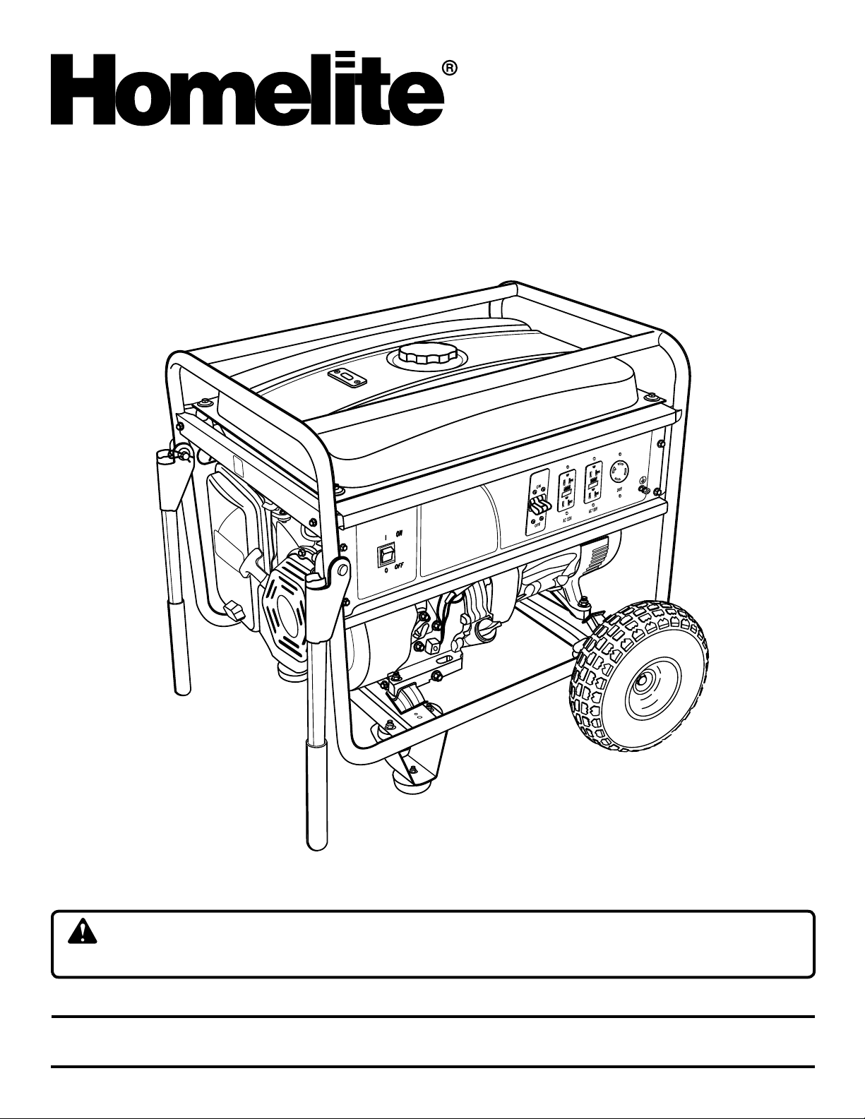
PORTABLE GENERATOR SET
6,000 WATT
HG6000
Your new generator has been engineered and manufactured to a high standard for dependability, ease of operation, and
operator safety. When properly cared for, it will give you years of rugged, trouble-free performance.
DANGER: You WILL be KILLED or SERIOUSLY HURT if you do not follow the instructions in this operator’s
manual.
Thank you for your purchase.
SAVE THIS MANUAL FOR FUTURE REFERENCE
Page 2
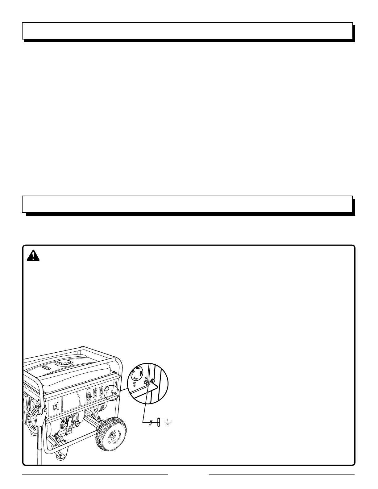
TABLE OF CONTENTS
FUEL
AC CIRCUIT
BREAKER
Introduction .................................................................................................................................................................... 2
General Safety Rules ..................................................................................................................................................... 3
Specific Safety Rules ..................................................................................................................................................... 4
Symbols ......................................................................................................................................................................5-7
Electrical .....................................................................................................................................................................8-9
Features .................................................................................................................................................................10-11
Loose Parts List ........................................................................................................................................................... 12
Assembly ................................................................................................................................................................13-14
Operation ................................................................................................................................................................14-16
Maintenance ...........................................................................................................................................................17-20
Troubleshooting ........................................................................................................................................................... 21
Wiring Diagram ............................................................................................................................................................ 22
Warranty ....................................................................................................................................................................... 23
Parts Ordering / Service .................................................................................................................................Back Page
INTRODUCTION
This product has many features for making its use more pleasant and enjoyable. Safety, performance, and dependability
have been given top priority in the design of this product, making it easy to maintain and operate.
DANGER
GROUNDING THE GENERATOR
To avoid the risk of shock or electrocution, generator must be properly grounded. The nut and ground terminal on the
frame must always be used to connect the generator to a suitable ground source. The ground path should be made
with #8 size wire. Connect the terminal of the ground wire between the lock washer and the nut, and tighten the nut
fully. Connect the other end of the wire securely to a suitable ground source.
The National Electric Code contains several practical ways in which to establish a good ground source. If a steel or iron
rod is used, it should be at least 5/8 in. diameter, and if a nonferrous rod is used, it should be at least 1/2 in. diameter
and be listed as material for grounding. Drive the rod or pipe to a depth of 8 ft. If a rock bottom is encountered less than
4 ft. down, bury the rod or pipe in a trench.
All electrical tools and appliances operated from this generator
must be properly grounded by use of a third wire or be “Double
Insulated.”
It is recommended to:
1. Use electrical devices with 3-prong grounded plugs.
2. Use an extension cord with a 3-pole receptacle and a
3-prong plug at opposite ends to ensure continuity of the
ground protection from the generator to the appliance.
Check and adhere to all applicable federal, state, and local
regulations relating to grounding specifications. Consult a qualified electrician or service personnel if the grounding instructions
are not completely understood or if in doubt as to whether the
generator is properly grounded.
Page 2
Page 3

GENERAL SAFETY RULES
WARNING:
Read and understand all instructions. Failure to follow
all instructions listed below may result in electrocution,
fire, and/or carbon monoxide poisoning, which will cause
death or serious injury.
Do not allow children or untrained individuals to use this
unit.
� Never start or run the engine inside a closed or partially
enclosed area. Breathing exhaust fumes will kill you.
� Wear eye protection which is marked to comply with ANSI
Z87.1 as well as hearing protection when operating this
equipment.
� Keep all bystanders, children, and pets at least 10 feet
away.
� Wear sturdy and dry shoes or boots. Do not operate while
barefoot.
� Do not operate generator when you are tired or under the
influence of drugs, alcohol, or medication.
� Keep all parts of your body away from any moving parts
and all hot surfaces of the unit.
� Product users on United States Forest Service land, and
in some states, must comply with fire prevention regulations. This product is not equipped with a spark arrestor.
Check with the federal, state, or local authorities in your
area before use.
Do not touch bare wire or receptacles.
Do not use generator with electrical cords which are
worn, frayed, bare, or otherwise damaged.
Before storing, allow the engine to cool.
Do not operate generator in rain, snow, or wet weather.
Empty fuel tank, close fuel valve, and restrain the unit
from moving before transporting in a vehicle.
Allow engine to cool for five minutes before refueling.
To reduce the risk of fire and burn injury, handle fuel with
care. It is highly flammable.
Do not smoke while handling fuel.
Store fuel in a container approved for gasoline.
Position the unit on level ground, stop engine, and allow
to cool before refueling.
Loosen fuel cap slowly to release pressure and to keep
fuel from escaping around the cap.
Tighten the fuel cap securely after refueling.
Wipe spilled fuel from the unit.
Never attempt to burn off spilled fuel under any circum-
stances.
Use only authorized replacement parts and accessories
and follow instructions in the Maintenance section of this
manual. Use of unauthorized parts or failure to follow
Maintenance instructions may create a risk of shock or
injury.
Maintain the unit per maintenance instructions in this
Operator’s Manual.
Inspect the unit before each use for loose fasteners, fuel
leaks, etc. Replace damaged parts.
National Electric Code requires generator to be grounded
to an approved earth ground. Before using the ground
terminal, consult a qualified electrician, electrical inspector, or local agency having jurisdiction for local codes
or ordinances that apply to the intended use of the
generator.
Page 3
Page 4

SPECIFIC SAFETY RULES
Exhaust contains poisonous carbon monoxide, a color-
less, odorless gas. Breathing exhaust can cause loss
of consciousness and can lead to death. If running in a
confined or partially-enclosed area, the air may contain
a dangerous amount of carbon monoxide. To keep exhaust fumes from building up, always provide adequate
ventilation.
Always use a battery-powered carbon monoxide detec-
tor when running the generator. If you begin to feel sick,
dizzy, or weak while using the generator, shut it off and
get to fresh air immediately. See a doctor. You may have
carbon monoxide poisoning.
Place the generator on a flat, stable surface with a slope
of no more than 4°.
Operate in a well-ventilated, well-lit area isolated from
working areas to avoid noise interference.
Operating the generator in wet conditions could result in
electrocution. Keep the unit dry.
Keep the generator a minimum of 3 feet away from all
types of combustible material.
Do not operate generator near hazardous material.
Do not operate generator at a gas or natural gas filling
station.
Do not touch the muffler or cylinder during or immediately
after use; they are HOT and will cause burn injury.
Do not connect to a building’s electrical system unless a
transfer switch has been properly installed by a qualified
electrician.
To connect a generator to your existing wiring, notify
your utility company that you are installing a generator
for backup power. Then have a licensed electrical contractor install a transfer switch. The transfer switch isolates
your home from the ability to “back feed” neutral power
lines. Failure to isolate the generator from power utility
can result in death or injury to electric utility workers.
Do not allow the generator’s gas tank to overflow when
filling. Fill to 1 in. below the top neck of the gasoline tank
to allow for fuel expansion. Check the ventilation hole inside the fuel tank cap for debris. Do not block the vent.
Do not smoke when filling the generator with gasoline.
Allow the engine to remain in a shut-down condition for
at least five minutes before adding gasoline or oil.
Do not remove the oil dipstick or the fuel tank cap when
the engine is running.
Pay close attention to all safety labels located on the
generator.
Keep children a minimum of 10 feet away from the gen-
erator at all times.
The unit operates best in temperatures between 23°F and
104°F with a relative humidity of 90% or less.
Specific modifications for high-altitude performance
are needed if the generator will always be operated at
altitudes above 5,000 feet. Contact your nearest Baja
authorized service center for more information and to
have these modifications performed.
Save these instructions. Refer to them frequently and use
them to instruct others who may use this tool. If you loan
someone this tool, loan them these instructions also.
Page 4
Page 5
SYMBOLS
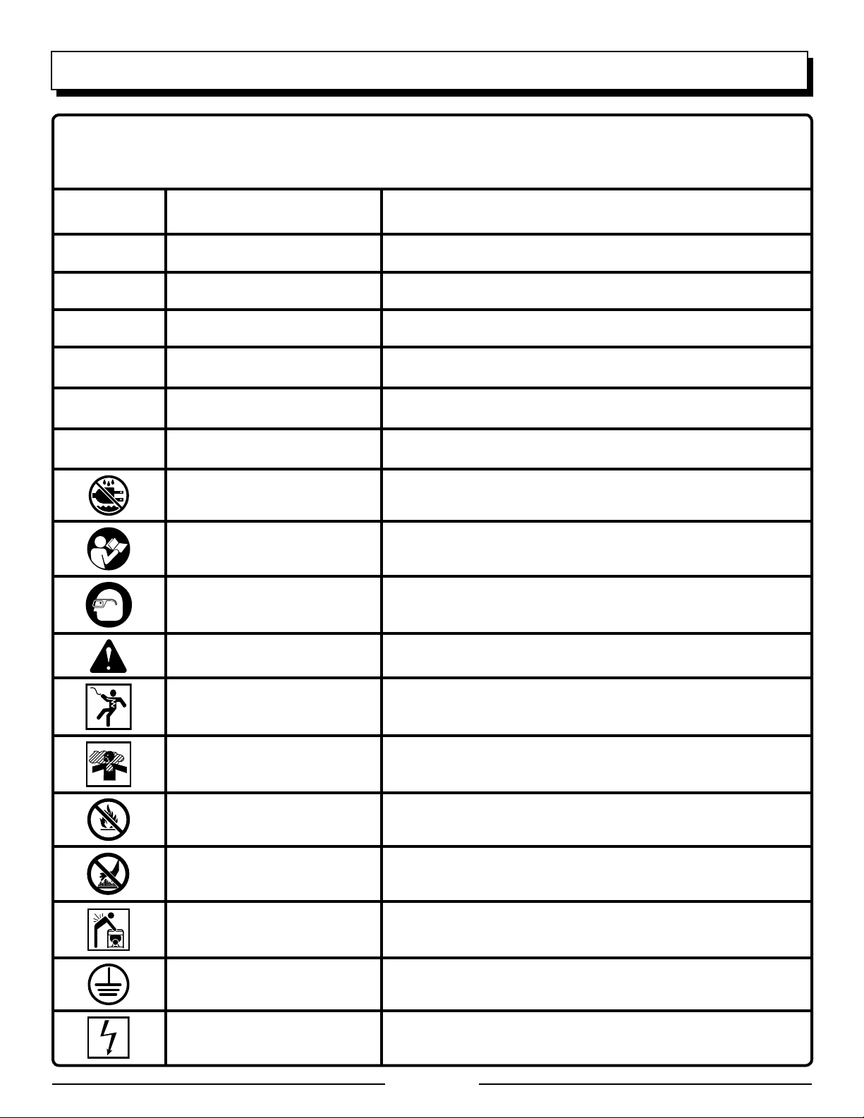
Some of the following symbols may be used on this product. Please study them and learn their meaning. Proper
interpretation of these symbols will allow you to operate the product better and safer.
SYMBOL NAME DESIGNATION/EXPLANATION
V Volts Voltage
A Amperes Current
Hz Hertz Frequency (cycles per second)
W Watt Power
hrs Hours Time
gal Gallon Volume
qt Quart Volume
Wet Conditions Alert Do not expose to rain or use in damp locations.
Read The Operator’s Manual
Eye Protection
Safety Alert Precautions that involve your safety.
Electric Shock
Toxic Fumes
Fire/Explosion
Hot Surface
To reduce the risk of injury, user must read and understand
operator’s manual before using this product.
Always wear safety goggles or safety glasses with side shields and,
as necessary, a full face shield when operating this product.
Failure to use in dry conditions and to observe safe practices can
result in electric shock.
Running generator gives off carbon monoxide, an odorless, colorless, poison gas. Breathing carbon monoxide can cause nausea,
fainting, or death.
Fuel and its vapors are extremely flammable and explosive. Fire
or explosion can cause severe burns or death.
To reduce the risk of injury or damage, avoid contact with any hot
surface.
Lifting Hazard
Ground
Electrocution
To reduce the risk of serious injury, avoid attempting to lift the
generator alone.
Consult with local electrician to determine grounding requirements
before operation.
Failure to properly ground generator can result in electrocution,
especially if the generator is equipped with a wheel kit.
Page 5
Page 6
SYMBOLS
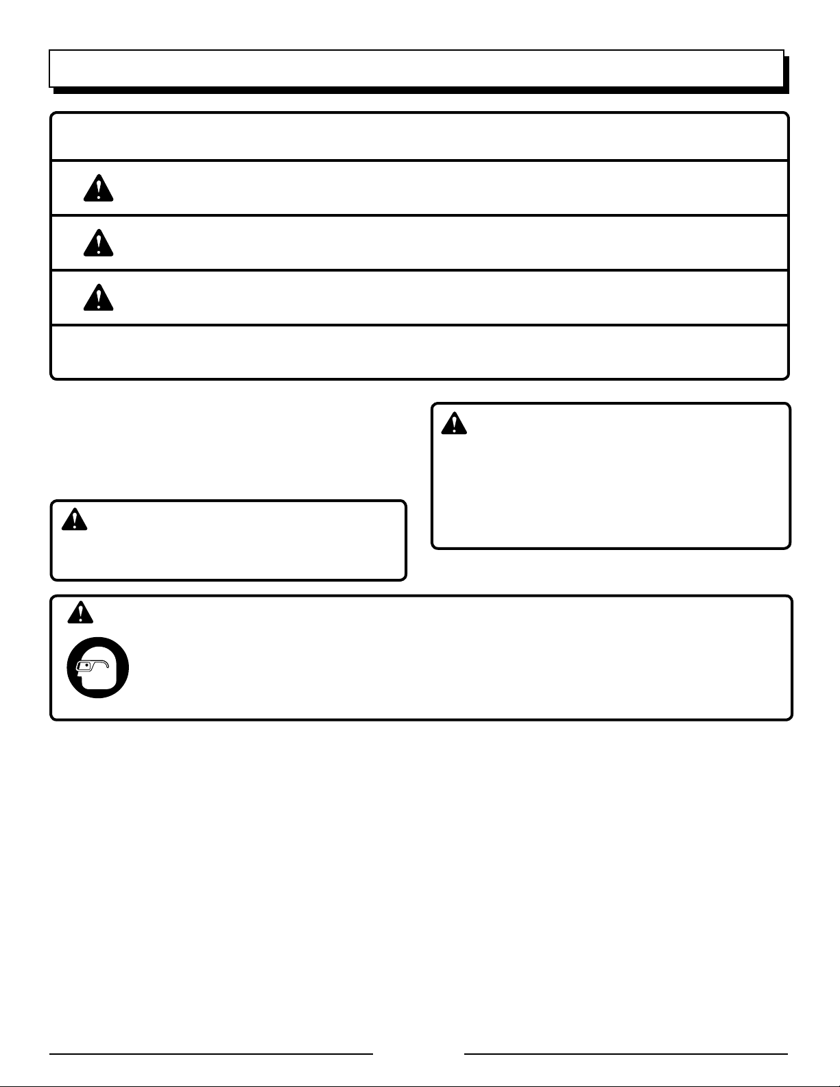
The following signal words and meanings are intended to explain the levels of risk associated with this product.
SYMBOL SIGNAL MEANING
DANGER:
WARNING:
CAUTION:
CAUTION:
Indicates an imminently hazardous situation, which, if not avoided, will result
in death or serious injury.
Indicates a potentially hazardous situation, which, if not avoided, could result
in death or serious injury.
Indicates a potentially hazardous situation, which, if not avoided, may result in
minor or moderate injury.
(Without Safety Alert Symbol) Indicates a situation that may result in property
damage.
SERVICE
Servicing requires extreme care and knowledge and should
be performed only by a qualified service technician. For
service, contact Baja Motorsports at 1-866-260-8280. When
servicing, use only identical replacement parts.
WARNING:
Observe all normal safety precautions related to avoid
electrical shock.
DANGER:
To avoid death or serious personal injury, do not attempt
to operate this product until you read thoroughly and
understand completely the operator’s manual. If you
do not understand the warnings and instructions in the
operator’s manual, do not use this product. Call Baja
customer service for assistance.
WARNING:
The operation of any products can result in foreign objects being thrown into your eyes, which can result in
severe eye damage. Before beginning power tool operation, always wear safety goggles or safety glasses
with side shields and, when needed, a full face shield. We recommend Wide Vision Safety Mask for use
over eyeglasses or standard safety glasses with side shields. Always wear eye protection which is marked
to comply with ANSI Z87.1.
SAVE THESE INSTRUCTIONS
Page 6
Page 7
SYMBOLS
This engine is equipped with an oil sensor.
Fill oil to upper level if failure to start.
WARNING
HOT
SURFACE
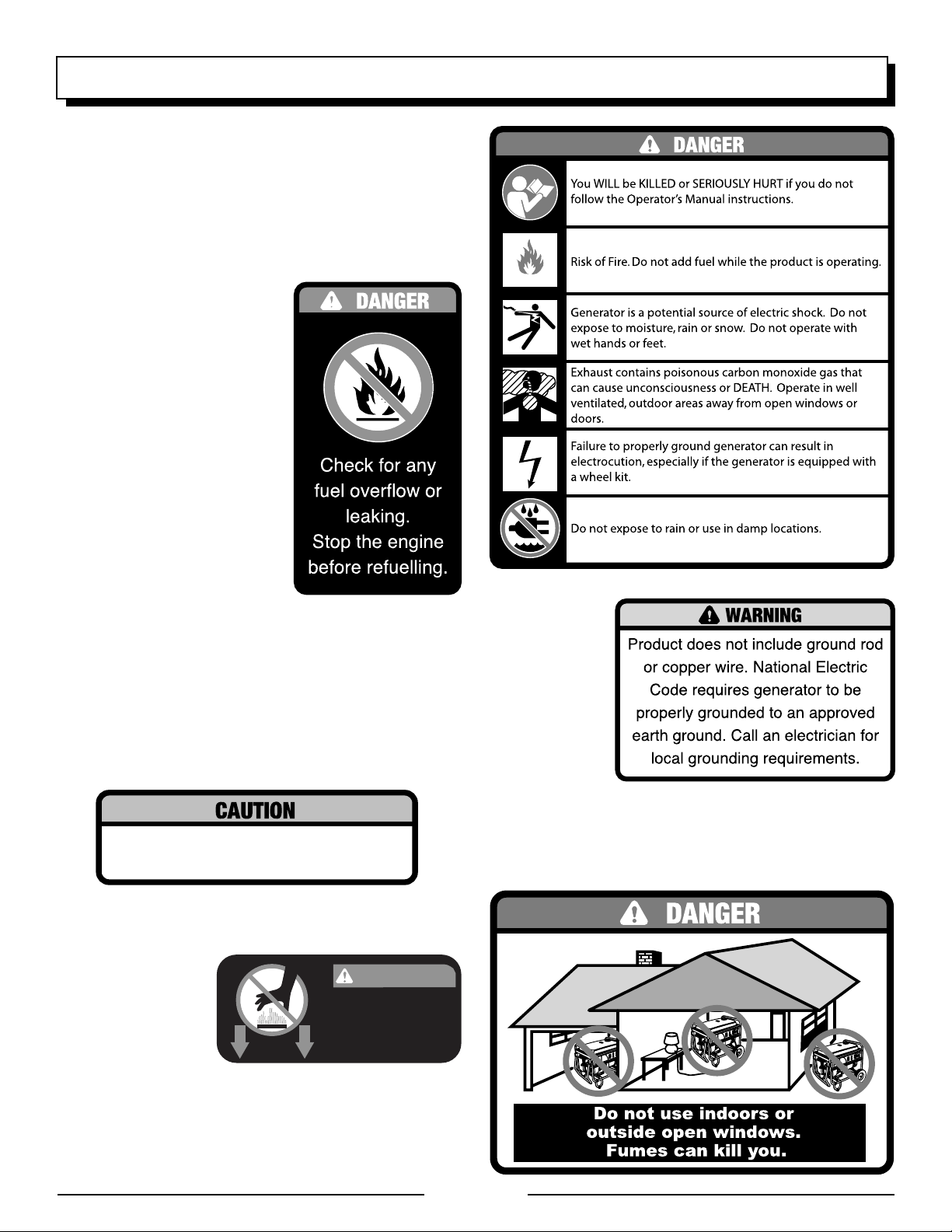
SAFETY LABELS
The information below can be found on the generator. For
your safety, please study and understand all of the labels
before starting the generator.
If any of the labels come off the unit or become hard to read,
contact a Baja authorized service center for replacement.
FUEL WARNING
No smoking when filling with
gasoline. Do not overfill. Full level
is 1 in. below the top of the fuel
neck. Stop the engine for five
minutes before refueling to avoid
the heat from the muffler igniting
fuel vapors.
ENGINE OIL WARNING
You must add oil before first operating the generator. The oil
reservoir capacity is 1.2 qt. Always check the oil level before
each operation. The oil level should always register within
the hatched area on the dipstick. The unit is equipped with
an oil sensor which will automatically shut off the engine if
oil level falls below a safe limit.
HOT SURFACE
WARNING
Do not tou ch the
muffler or aluminum
cylinder of the engine.
They are very HOT
and will cause severe
burns. Don’t put any flammable or combustible materials in
the direct path of the exhaust.
GROUNDING
WARNING
National Electric
Code requi res
generator to be
grounded to an
approved earth
ground.
VENTILATION WARNING
Do not use the generator in an enclosed area or near open
windows, vents, or doors. Fumes from the unit can kill.
Page 7
Page 8
ELECTRICAL
EXTENSION CORD CABLE SIZE
Refer to the table below to ensure the cable size of the extension cords you use are capable of carrying the required load.
Inadequate size cables can cause a voltage drop, which can burn out the appliance and overheat the cord.
Current in
Amperes
2.5 300 600 1000 ft. 600 ft. 375 ft. 250 ft.
5 600 1200 500 ft. 300 ft. 200 ft. 125 ft.
7.5 900 1800 350 ft. 200 ft. 125 ft. 100 ft.
10 1200 2400 250 ft. 150 ft. 100 ft. 50 ft.
15 1800 3600 150 ft. 100 ft. 65 ft.
20 2400 4800 175 ft. 125 ft. 75 ft.
25 3000 6000 150 ft. 100 ft.
30 3600 7200 125 ft. 65 ft.
40 4800 9600 90 ft.
Load in Watts Maximum Allowable Cord Length
At 120V At 240V #8 Wire #10 Wire #12 Wire #14 Wire #16 Wire
ELECTRIC MOTOR LOADS
It is characteristic of common electric motors in normal operation to draw up to six times their running current while starting. This table may be used to estimate the watts required to start “Code G” electric motors; however, if an electric motor
fails to start or reach running speed, turn off the appliance or tool immediately to avoid equipment damage. Always check
the requirements of the tool or appliance being used compared to the rated output of the generator.
Motor Size (H.P.) Running Watts
1/8 275 600 850 1200
1/6 275 600 850 2050
1/4 400 850 1050 2400
1/3 450 975 1350 2700
1/2 600 1300 1800 3600
3/4 850 1900 2600 —
1 1100 2500 3300 —
Repulsion Induction Capacitor Split Phase
Watts Required to Start Motor
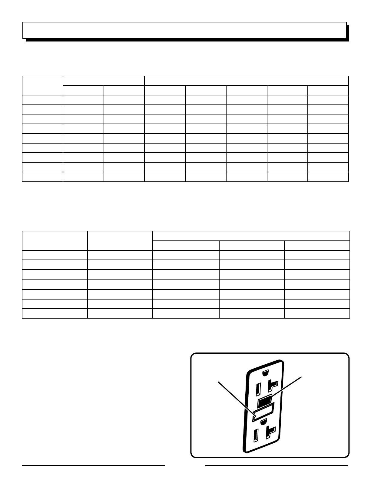
GROUND FAULT CIRCUIT INTERRUPTER
The 20 amp, 120 volt receptacles on the generator are protected by a Ground Fault Circuit Interrupter (GFCI), which
guards against the hazards of ground fault currents. An
example of ground fault current is the current that would
flow through a person who is using an appliance with faulty
insulation and, at the same time, is in contact with an electrical
ground such as a plumbing fixture, wet floor, or earth.
GFCI receptacles do not protect against short circuits,
overloads, or shocks.
The GFCI receptacles can be tested with the TEST and
RESET buttons.
To test:
Depress the TEST button. This should cause the Reset
button to pop out.
To restore power, depress the RESET button.
Page 8
Perform this test monthly to ensure proper operation of the
GFCI. If the generator is stored outdoors, unprotected from
the weather, test the GFCI receptacle before each use.
RESET BUTTON
TEST BUTTON
Fig. 1
Page 9

ELECTRICAL
GENERATOR CAPACITY
Make sure the generator can supply enough continuous (running) and surge (starting) watts for the items you will power
at the same time. Follow these simple steps.
�1. Select the items you will power at the same time.
�2. Total the continuous (running) watts of these items. This
is the amount of power the generator must produce to
keep the items running. See the wattage reference chart
at right.
�3. Estimate how many surge (starting) watts you will need.
Surge wattage is the short burst of power needed to
start electric motor-driven tools or appliances such as a
circular saw or refrigerator. Because not all motors start
at the same time, total surge watts can be estimated by
adding only the item(s) with the highest additional surge
watts to the total rated watts from step 2.
Example:
Tool or Appliance
Window AC,
10,000 BTU
Continuous
(Running) Watts
1200 1800
Surge
(Starting) Watts
Refrigerator 700 2200
1/3 HP Well Pump 1000 2000
27 in. Television 500 0
Light (75 Watts) 75 0
3475 Total
Running Watts
2200 Highest
Surge Watts
Total Continuous (Running) Watts 3475
Plus Highest Additional Surge Watts + 2200
Equals Total Generator Output Required 5675
POWER MANAGEMENT
To prolong the life of the generator and attached devices,
it is important to take care when adding electrical loads to
the generator. There should be nothing connected to the
generator outlets before starting its engine. The correct and
safe way to manage generator power is to sequentially add
loads as follows:
1. With nothing connected to the generator, start the engine
as described later in this manual.
2. Plug in and turn on the first load, preferably the largest
load you have.
3. Permit the generator output to stabilize (engine runs
smoothly and attached device operates properly).
4. Plug in and turn on the next load.
5. Again, permit the generator to stabilize.
6. Repeat steps 4 and 5 for each additional load.
Never add more loads than the generator capacity. Take
special care to consider surge loads in generator capacity
as previously described.
CAUTION:
Do not overload the generator’s capacity. Exceeding the
generator’s wattage/amperage capacity can damage the
generator and/or electrical devices connected to it.
Typical
Tool or Appliance
Essentials
Light Bulb − 75 Watt 75 75
Refrigerator/Freezer 700 2200
Sump Pump − 1/2 HP 1050 2200
Water Well Pump − 1/3 HP 1000 1500
Electric Water Heater 4000 0
Heating/Cooling
Furnace Fan − 1/2 HP 800 2350
Window AC − 10,000 BTU 1200 1800
Space Heater 1800 0
Kitchen
Microwave Oven − 1000 Watt 1000 0
Coffee Maker 1000 0
Electric Stove − Single Element 2100 0
Toaster Oven 1200 0
Family Room
VCR 100 0
CD/DVD Player 100 0
Stereo Receiver 450 0
Color Television − 27 in. 500 0
Other
Security System 500 0
Curling Iron 1500 0
Garage Door Opener − 1/2 HP 875 2350
Hair Dryer − 1/2 HP 1250 0
DIY/Job Site
Quartz Halogen Work Light 1000 0
Airless Sprayer − 1/3 HP 600 1200
Reciprocating Saw 960 0
Electric Drill − 1/2 HP 600 900
Circular Saw − 7-1/4 in. 1400 2300
Miter Saw − 10 in. 1800 1800
Planer/Jointer − 6 in. 1800 1800
Table Saw/Radial Arm Saw − 10 in. 2000 2000
Air Compressor − 1 HP 1600 4500
*Wattages listed are approximate. Check tool or appliance for actual wattage.
Continuous*
(Running)
Watts
Typical
Surge
(Starting)
Watts
Page 9
Page 10

FUEL
AC CIRCUIT
BREAKER
FEATURES
PRODUCT SPECIFICATIONS
ENGINE
Engine Type ................................ 4 Stroke, Overhead Valve
Bore x Stroke ............................................. 88 mm x 64 mm
Cooling System .................................................. Forced Air
Compression Ratio .........................................................8:1
Starting System ......................................................... Recoil
Ignition System ............................................................T.C.I.
Spark Plug .................................................. TORCH F7RTC
Engine Oil Volume ..................................................... 1.2 qt.
Fuel Volume ............................................................. 6.5 gal.
GENERATOR
Rated Voltage .................................................... 120V/240V
Rated Amps ................................................................22.9A
Rated Output ..........................................................5,500 W
Maximum Output ...................................................6,000 W
Rated Frequency ........................................................60 Hz
DIMENSIONS
Length ................................................................... 32.67 in.
Width ..................................................................... 26.77 in.
Height ...................................................................... 24.6 in.
Net Weight .............................................................. 202 lbs.
CHOKE
LEVER
AIR FILTER
FUEL VALVE
FUEL TANK
FUEL LEVEL
GAUGE
FUEL CAP
AC CIRCUIT
BREAKER
120 VOLT AC
20 AMP GFCI
RECEPTACLES
240 VOLT AC
30 AMP
RECEPTACLE
GROUND
TERMINAL
RECOIL STARTER
GRIP
ENGINE
SWITCH
OIL DRAINAGE
Page 10
OIL CAP/ DIPSTICK
BOLT
Fig. 2
Page 11

FEATURES
KNOW YOUR GENERATOR
See Figure 2.
The safe use of this product requires an understanding of the
information on the product and in this operator’s manual as
well as a knowledge of the project you are attempting. Before
use of this product, familiarize yourself with all operating
features and safety rules.
AC CIRCUIT BREAKER
The circuit breaker is provided to protect the generator against
electrical overload and can be used to turn the generator’s
electrical power on or off.
AIR FILTER
The air filter helps to limit the amount of dirt and dust drawn
into the unit during operation.
CHOKE LEVER
The choke lever is used when starting the engine.
ENGINE SWITCH
The engine switch is used in combination with the recoil
starter grip to start the generator. It is also used to turn the
generator off.
FUEL VALVE
The flow of fuel through the generator is controlled by the
position of the fuel valve.
GROUND TERMINAL
The ground terminal is used to assist in properly grounding the generator to help protect against electrical shock.
Consult with a local electrician for grounding requirements
in your area.
OIL DRAINAGE BOLT
When changing the engine oil, the oil drainage bolt is loosened to allow old engine oil to be drained.
OIL CAP/DIPSTICK
Remove the oil fill cap to check and add oil to the generator
when necessary.
RECEPTACLES
Your generator has the following single phase, 60 Hz outlets:
four 120 Volt AC, 20 Amp GFCI receptacles, and one 240
Volt AC, 30 Amp receptacle. These can be used for operating appropriate appliances, electrical lighting, tools, and
motor loads.
FUEL LEVEL GAUGE
Consult the fuel level gauge to determine the amount of fuel
remaining in the generator.
FUEL TANK
The fuel tank has a capacity of 6.5 gallons.
RECOIL STARTER GRIP
The recoil starter grip is used (along with the engine switch)
to start the generator’s engine.
Page 11
Page 12

LOOSE PARTS LIST
The following items are included with the generator:
3
2
8
1
6
5
4
7
Key
No. Description ....................................................Qty.
1 Wheels .................................................................2
2 Wheel Axle ...........................................................2
3 Large Cotter Pin ..................................................2
4 Small Cotter Pin ..................................................4
5 Clevis Pin .............................................................2
6 Handle .................................................................2
Page 12
Key
No. Description ....................................................Qty.
7 Bolt ......................................................................6
8 Frame Support with Foot ....................................2
10W-30 4-Cycle Engine Oil
(34 fl. oz., not shown) ..........................................1
Registration Card (not shown) .............................1
Operator’s Manual (not shown) ...........................1
Page 13

ASSEMBLY
UNPACKING
This product requires assembly.
Remove one end of the box and carefully slide out the
generator and any accessories.
NOTE: The generator is heavy. If you must lift the unit
out of the box, get another person to help you and lift
with your legs, not your back.
Inspect the unit carefully to make sure no damage oc-
curred during shipping.
Do not discard the packing material until you have carefully
inspected and satisfactorily operated the product.
If any parts are damaged or missing, please call
1-866-260-8280 for assistance.
WARNING:
If any parts are damaged or missing do not operate
this product until the parts are replaced. Failure to heed
this warning could result in serious personal injury.
WARNING:
Do not attempt to modify this tool or create accessories not
recommended for use with this tool. Any such alteration
or modification is misuse and could result in a hazardous
condition leading to possible serious personal injury.
U-BRACKET
BOLT
WHEEL
AXLE
SMALL
COTTER
PIN
WHEEL
LARGE
COTTER
PIN
Fig. 3
HOLE
FRAME SUPPORT
WITH FOOT
WARNING:
Do not attempt to operate the generator until assembly
is complete. Failure to comply could result in possible
serious personal injury.
INSTALLING THE WHEELS
See Figure 3.
Wheels are provided to assist in moving the generator to the
desired location and should be installed on the side opposite
the recoil starter.
NOTE: Install the wheels before installing the handle. Do not
put fuel or oil in the generator before installing the wheels.
Locate the following items:
2 wheel axles 2 wheels
2 small cotter pins 2 large cotter pins
Raise the end of the generator opposite the recoil starter
high enough to gain access to the frame bottom; securely
position props underneath to support.
Locate the U-bracket on one side of the frame bottom.
Slide a wheel axle through the bracket so that an end
extends from both sides of the bracket.
On the end that extends inside the generator frame, insert
a small cotter pin through the hole in the axle to secure.
Bend the ends of the cotter pin to prevent the pin from
slipping out.
Fig. 4
Place a wheel over the other end of the axle.
Insert a large cotter pin through the hole in the axle. Bend
the ends of the pin to secure.
Repeat the process on the other side.
INSTALLING THE FRAME SUPPORTS
See Figure 4.
Install the two frame supports provided on the bottom side
of the generator frame opposite the wheels.
Locate the following items:
2 frame supports 6 bolts
Raise the end of the generator where the recoil starter is
located high enough to gain access to the frame bottom;
securely position props underneath to support.
Align the holes on the frame support with the holes on
the generator frame.
Insert a bolt through the hole in the generator frame so it
extends down through the frame support.
Tighten bolt to secure.
Repeat with the two remaining screws.
Repeat on other side to install second frame support.
Page 13
Page 14

ASSEMBLY
INSTALLING THE HANDLES
See Figure 5.
Locate the following items:
2 handles 2 clevis pins
2 small cotter pins
With the generator in normal operating position, find the
holes on the frame above the recoil starter.
Align the holes in one of the handle brackets with the
holes in one side of the generator frame.
Insert a clevis pin through the handle bracket and frame.
The head of the pin should be on the outside of the
frame.
Insert the small cotter pin through the hole in the clevis
pin. Bend the ends of the pin to secure.
Repeat the above steps to install the second handle.
CAUTION
Do not attempt to lift the unit by the handle assembly.
If it is necessary to lift the generator, always grasp by
the frame. Use proper lifting techniques to avoid back
injury.
COTTER PIN
CLEVIS PIN
GENERATOR
FRAME
HANDLE
Fig. 5
OPERATION
DANGER:
Failure to properly ground generator can result in electrocution, especially if the generator is equipped with a
wheel kit. National Electric Code requires generator to be
properly grounded to an approved earth ground. Call an
electrician for local grounding requirements.
WARNING:
Do not allow familiarity with tools to make you careless.
Remember that a careless fraction of a second is sufficient to inflict serious injury.
WARNING:
Do not use any attachments or accessories not
recommended by the manufacturer of this product. The
use of attachments or accessories not recommended
can result in serious personal injury.
APPLICATIONS
This generator is designed to supply electrical power for
operating compatible electrical lighting, appliances, tools,
and motor loads.
Page 14
Page 15
FUEL
AC CIRCUIT
BREAKER
OPERATION
BEFORE OPERATING THE UNIT
Position the generator on a flat surface before checking fluid
levels or adding fluid.
CAUTION:
Attempting to start the engine before it has been properly
filled with oil will result in equipment failure.
CHECKING/ADDING OIL
See Figure 6.
Engine oil has a major influence on engine performance and
service life. For general, all-temperature use, SAE 10W-30 is
recommended. Always use a 4-stroke motor oil that meets or
exceeds the requirements for API service classification SJ.
NOTE: Non-detergent or 2-stroke engine oils will damage
the engine and should not be used.
Unscrew the oil cap/dipstick and remove.
Wipe dipstick clean and re-seat in hole; do not re-
thread.
Remove dipstick again and check oil level. Oil level should
fall within the hatched area on the dipstick.
If level is low, add engine oil until the fluid level rises to
the upper portion of the hatched area on the dipstick.
Replace and secure the oil cap/dipstick.
OIL CAP/
DIPSTICK
OIL FILL
HOLE
Fig. 6
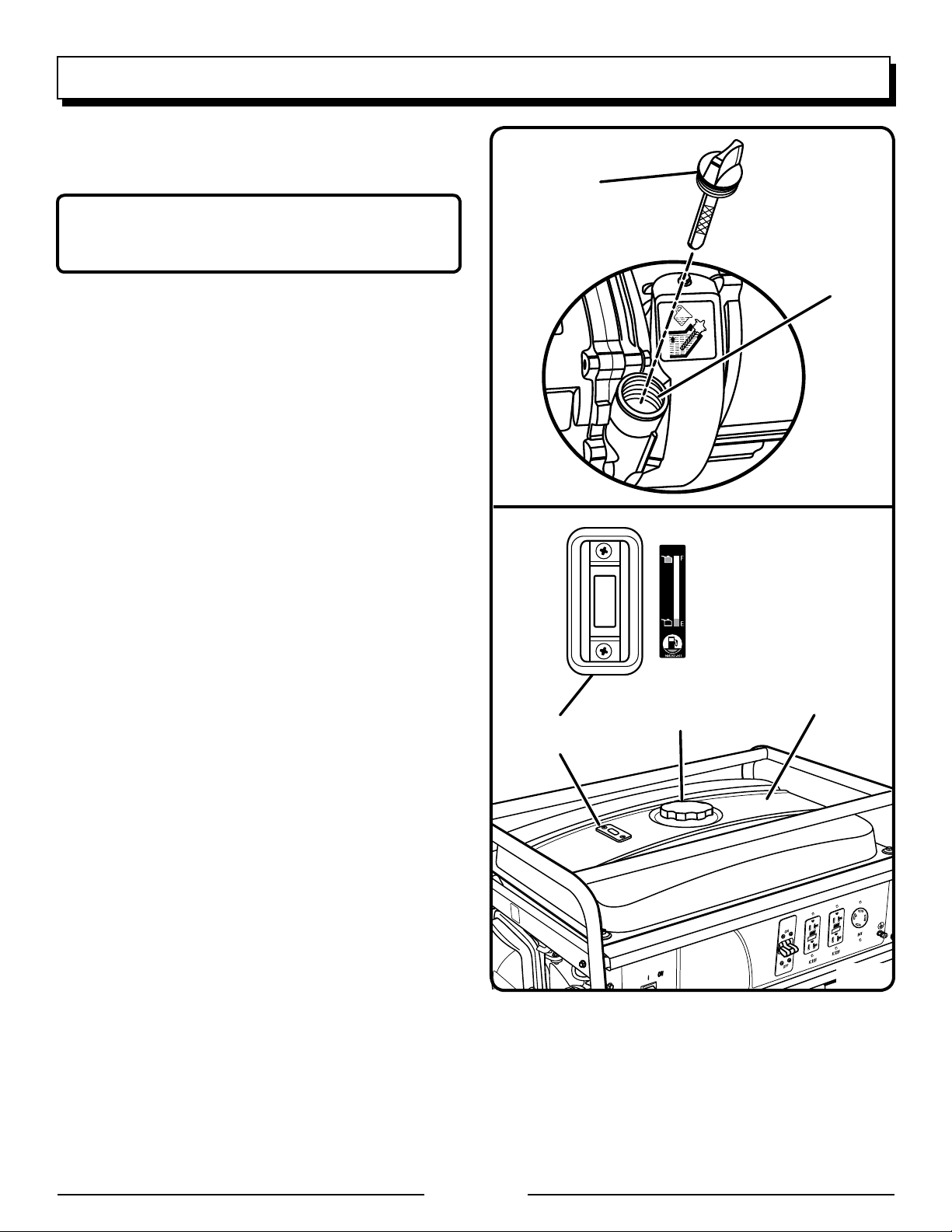
CHECKING/ADDING FUEL
See Figure 7.
Check the fuel level gauge. If fuel is needed, continue
with the next step.
Remove the fuel cap.
Fill the fuel tank to 1 in. below the top of the fuel neck.
Replace and secure the fuel cap.
NOTE: Always use unleaded gasoline with a pump octane
rating of 86 or higher. Never use old, stale, or contaminated
gasoline, and do not use an oil/gas mixture. Do not allow
dirt or water into the fuel tank.
USING FUEL STABILIZER
Fuel gets old, oxidizes, and breaks down over time. Adding a fuel stabilizer extends the usable life of fuel and helps
prevent deposits from forming that can clog the fuel system.
Follow fuel stabilizer manufacturer’s directions for correct
ratio of stabilizer to fuel.
Add stabilizer to fuel tank, then fill with gasoline following
previous instructions.
NOTE: Fuel stabilizer and gasoline can be mixed prior
to filling the tank by using a gas can or other approved
fuel container and shaking gently to combine.
Replace and secure the fuel tank cap.
Start and run the engine for at least 5 minutes to allow
stabilizer to treat the entire fuel system.
FUEL TANK
FUEL LEVEL
FUEL CAP
GAUGE
OXYGENATED FUELS
Some conventional gasolines are blended with alcohol or an
ether compound. These gasolines are collectively referred
to as oxygenated fuels. To meet clean air standards, some
areas of the United States and Canada use oxygenated fuels
to help reduce emissions.
Page 15
Fig. 7
Page 16

FUEL
AC CIRCUIT
BREAKER
OPERATION
If using an oxygenated fuel, make sure it is unleaded and
meets the minimum octane rating requirements. Before using
an oxygenated fuel, try to confirm the fuel’s contents. Some
states/provinces require this information to be posted on the
pump. The following are the EPA approved percentages of
oxygenates:
Ethanol (ethyl or grain alcohol) 10% by volume. You
may use gasoline containing up to 10% ethanol by volume.
Gasoline containing ethanol may be marketed under the
name “Gasohol.”
MTBE (methyl tertiary butyl ether) 15% by volume. You
may use gasoline containing up to 15% MTBE by volume.
Methanol (methyl or wood alcohol) 5% by volume. You
may use gasoline containing up to 5% methanol by volume
as long as it also contains cosolvents and corrosion inhibitors to protect the fuel system. Gasoline containing more
than 5% methanol by volume may cause starting and/or
performance problems. It may also damage metal, rubber,
and plastic parts of the generator or your fuel system.
If you notice any undesirable operating symptoms, try another
service station or switch to another brand of gasoline.
NOTE: Fuel system damage or performance problems resulting from the use of an oxygenated fuel containing more
than the percentages of oxygenates stated previously are
not covered under warranty.
CAUTION:
On a level surface with the engine off, check the oil level
before each use of the generator.
RECOIL
STARTER
GRIP
ENGINE
SWITCH
CIRCUIT
BREAKER
Fig. 8
FUEL
VALVE
Fig. 9
PULL CHOKE
LEVER OUT
TO START
STARTING THE ENGINE
See Figures 8 - 10.
NOTE: If location of generator is not level, the unit may not
start or may shut down during operation.
Unplug all loads from the generator.
Switch the AC circuit breakers to the OFF ( O ) position.
Turn the fuel valve to the ON position.
Pull the choke lever to the START position.
NOTE: If engine is warm or the temperature is above
50˚F, push the choke lever in to the RUN position.
Put the engine switch in the ON ( I ) position.
Pull the recoil starting grip until the engine runs (a maxi-
mum of 6 times).
NOTE: Do not allow the grip to snap back after starting;
return it gently to its original place.
Allow the engine to run for 30 seconds, then push the
choke lever in to the RUN position.
Switch the AC circuit breakers to the ON position.
PUSH CHOKE
LEVER IN TO RUN
Fig. 10
STOPPING THE ENGINE
See Figures 8 - 9.
To stop the engine under normal operating conditions:
Remove any load from the generator.
Place the voltage selector in the center (OFF) position.
Switch the AC circuit breakers to the OFF position.
Turn the fuel valve to the OFF position.
Put the engine switch in the OFF ( O ) position.
To stop the engine in an emergency situation:
Put the engine switch in the OFF ( O ) position.
Page 16
Page 17

AC CIRCUIT
BREAKER
MAINTENANCE
WARNING:
When servicing, use only identical Homelite replacement
parts. Use of any other parts may create a hazard or
cause product damage.
Only the parts shown on the parts list are intended to be
repaired or replaced by the customer. All other parts should
be replaced at a Baja authorized service center.
GENERAL MAINTENANCE
Keep the generator in a clean and dry environment where it
is not exposed to dust, dirt, moisture, or corrosive vapors.
Do not allow the cooling air slots in the generator to become
clogged with foreign material such as leaves, snow, etc.
Do not use a garden hose to clean the generator. Water entering the fuel system or other internal parts of the unit can
cause problems that will decrease the life of the generator.
To clean the unit:
Use a soft bristle brush and/or vacuum cleaner to loosen
and remove dirt and debris.
Clean air vents with low pressure air that does not exceed
25 psi.
Wipe the exterior surfaces of the generator with a damp
cloth.
AIR FILTER
COVER
KNOB
FILTER
ELEMENT
AIR FILTER
UNIT
Fig. 11
CHECKING/CLEANING AIR FILTER
See Figure 11.
For proper performance and long life, keep air filter clean.
Rotate the knob counterclockwise to release.
Lift the air filter cover toward you and up to remove from
the air filter unit.
Remove the filter element.
If the filter element is dirty, clean with warm, soapy water.
Rinse and let dry.
Apply a light coat of engine oil to the elements, then
squeeze it out.
Replace the element in the air filter unit.
Replace the air filter cover.
Reinstall the knob and rotate clockwise to secure.
NOTE: Do not run the generator without the air filter. Rapid
engine wear will result.
CHANGING ENGINE OIL
See Figure 12.
Remove the oil cap/dipstick.
Place a container underneath the oil drainage bolt to
collect used oil as it drains.
OIL CAP/
DIPSTICK
OIL DRAINAGE
BOLT
Unscrew the oil drainage bolt and remove.
Allow oil to drain completely.
Reinstall the oil drainage bolt and tighten securely.
Refill with oil following the instructions in the Checking/
Adding Oil section.
Reinstall the oil cap/dipstick.
NOTE: Used oil should be disposed of at an approved disposal site. See your local oil retailer for more information.
Fig. 12
Page 17
Page 18

MAINTENANCE
CLEANING FUEL SEDIMENT CUP
See Figure 13.
The sediment cup prevents dirt and water that may have
gotten into the fuel tank from entering the carburetor. If the
engine has not been run for a long time, the sediment cup
should be cleaned before use.
Turn the fuel valve to the OFF position.
Remove the sediment cup using a 10 mm wrench (not
provided).
Remove the O-ring and filter.
Clean each of the parts in carburetor cleaner or any
comparable cleaning product.
Reinstall the filter, O-ring, and sediment cup. Tighten with
wrench to secure.
Return the fuel valve to ON position and check for
leaks.
FUEL
VALVE
FILTER
O-RING
SPARK PLUG MAINTENANCE
See Figure 14.
The spark plug must be properly gapped and free of deposits
in order to ensure proper engine operation. To check:
Remove the spark plug cap.
Clean any dirt from around base of spark plug.
Remove spark plug using wrench provided.
Inspect spark plug for damage, and clean with a wire
brush before reinstalling. If insulator is cracked or chipped,
spark plug should be replaced.
NOTE: If replacing, use the following recommended
spark plugs or equivalent: Champion RN9YC or NGK
BPR5ES.
Measure plug gap. The correct gap is 0.028−0.031 in.
(0.7-0.8 mm). To widen gap, if necessary, carefully bend
the ground (top) electrode. To lessen gap, gently tap
ground electrode on a hard surface.
Seat spark plug in position; thread in by hand to prevent
cross-threading.
Tighten with wrench to compress washer. If spark plug
is new, use 1/2 turn to compress washer appropriate
amount. If reusing old spark plug, use 1/8 to 1/4 turn for
proper washer compression.
NOTE: An improperly tightened spark plug will become
very hot and could damage the engine.
SEDIMENT
CUP
Fig. 13
SPARK
PLUG
SPARK
PLUG
CAP
Fig. 14
Page 18
Page 19

MAINTENANCE
CLEANING THE EXHAUST PORT AND
MUFFLER
Depending on the type of fuel used, the type and amount of
oil used, and/or your operating conditions, the exhaust port
and muffler may become blocked with carbon deposits. If
you notice a power loss with your gas-powered tool, you
may need to remove these deposits to restore performance.
We highly recommend that only qualified service technicians
perform this service.
SPARK ARRESTOR
Product users on United States Forest Service land, and in
some states, must comply with fire prevention regulations.
This product is not equipped with a spark arrestor. To purchase a spark arrestor for the generator, contact Baja customer service at 1-866-260-8280 and request part number
H60-130.
DRAINING FUEL TANK/CARBURETOR
See Figures 15 - 16.
When not using a fuel stabilizer, draining the fuel from the
tank and carburetor before storage may help prevent gum
deposits in the fuel system.
DRAINING THE FUEL TANK
Turn the engine switch OFF ( O ).
�Close fuel valve.
� Remove the fuel line from the petcock by squeezing the
ends of the retaining clip and sliding the fuel line off.
Install one end of a drain line over the petcock, and place
the other end in a fuel container large enough to catch
the fuel being drained from the tank.
Open fuel valve.
When the fuel has drained from the tank, close the fuel
valve and reinstall fuel line on petcock.
DRAINING THE CARBURETOR
Turn the engine switch OFF ( O ).
Close the fuel valve.
Position a suitable container under the carburetor drain
screw to catch fuel; loosen the screw.
Allow fuel to drain completely into container.
Retighten drain screw.
FUEL
LINE
NOTE: Consult hazardous waste management guidelines in
your area for the proper way to dispose of used fuel.
FUEL
VALVE
PETCOCK
Fig. 15
CARBURETOR
DRAIN SCREW
Fig. 16
TRANSPORTING
Turn engine switch OFF ( O ).
Close the fuel valve.
Make sure engine and exhaust of unit is cool.
Keep unit level to prevent fuel spillage.
Do not drop or strike unit or place under heavy objects.
Page 19
Page 20

MAINTENANCE
STORAGE
When preparing the generator for storage, follow the guidelines below.
STORAGE TIME PRIOR TO STORING
Less than 1 month No special preparation is required.
1 to 2 months Fill with fresh gasoline and add a gasoline stabilizer*.
2 months to 1 year Fill with fresh gasoline and add a gasoline stabilizer*.
Drain fuel from carburetor.
Clean fuel sediment cup.
1 year or more Fill with fresh gasoline and add a gasoline stabilizer*.
Drain fuel from the carburetor.
� Clean fuel sediment cup.
� Remove spark plug.
Put a tablespoon of engine oil into the spark plug cylinder. Turn the engine slowly with the pull
rope to distribute the oil.
� Reinstall spark plug.
Change engine oil.
After removal from storage:
Drain and dispose of stored gasoline in a suitable container.
Fill with fresh gasoline.
*Use gasoline stabilizers formulated to extend storage life. For recommendations, contact your nearest Baja authorized
service center.
MAINTENANCE SCHEDULE
Before
each use
Check Engine Oil
Change Engine Oil
Check Air Filter
Clean Air Filter
Change Air Filter
Clean Carburetor
Sediment Cup
Check/Adjust Spark Plug
Replace Spark Plug
Check/Adjust Idle Speed
Check/Adjust Valve
Clearance*
Clean Fuel Tank and
Filter*
Check Fuel Tube
* These items should only be carried out by a Baja authorized service center.
NOTE: Maintenance should be performed more frequently when generator is used in dusty areas.
When generator has exceeded the maximum figures specified in the table, maintenance should still be cycled
according to the intervals of time or hours stated herein.
After 1st month
or 20 hours of
operation
Every 3 months
or 50 hours of
operation
Every 6 months
or 100 hours
of operation
Every year or
after 300 hours
of operation
Page 20
Page 21

TROUBLESHOOTING
PROBLEM POSSIBLE CAUSE SOLUTION
Engine will not start. Engine switch is OFF.
No fuel.
Oil level is low.
Fuel valve is OFF.
Spark plug faulty, fouled, or improperly
gapped.
Fuel is not reaching carburetor.
Choke is OPEN.
Engine stored without treating or
draining gasoline, or refueled with bad
gasoline.
Engine lacks power. Fuel element clogged.
Engine stored without treating or
draining gasoline, or refueled with bad
gasoline.
AC receptacle does not work. Circuit breaker is OFF.
Item plugged in is defective.
Generator makes a “spark knock” or
“pinging” noise.
If problem persists after trying the above solutions, contact your nearest Baja authorized service center for assistance.
An occasional light “knocking” or “pinging” under heavy load is not a cause
for concern. However, if the knocking
or pinging occurs under normal load
at a steady engine speed, the problem
may be with the brand of gasoline being used.
Turn engine switch to ON.
Fill fuel tank.
Check engine oil level and fill, if
necessary.
Turn fuel valve ON.
Replace spark plug.
Clean fuel sediment cup.
Pull choke lever out to CLOSED.
Drain fuel and carburetor. Refuel with
fresh gasoline.
Check air filter element. Clean or replace
as needed.
Drain fuel and carburetor. Refuel with
fresh gasoline.
Turn ON the AC circuit breaker.
Try a different item.
Switch to a different brand of gasoline,
making sure that the octane rating is 86
or higher. If problem continues, contact
your nearest Baja authorized service
center.
The following symptoms may indicate problems that will affect the emissions level of the unit:
Hard starting or stalling after starting
Rough idle
Misfiring or backfiring under load
Afterburning (backfiring)
Black exhaust smoke or high fuel consumption
If you encounter any of these symptoms, have the unit inspected and repaired by the nearest Baja authorized service
center.
Page 21
Page 22

WIRING DIAGRAM
Generator symbolic circuit
Excition
winding
Minior
winding
DC winding
Main winding
Main winding
Breaker 23A
Breaker 23A
Ground
Ground
Spark plug
Ground
IGNITION coil(IG)
Ground
oil SENSOR
Ground (G)
Ground
GFCI Socket(20A)
Socket
(30A)
Commutator
Control box
Engine switch (E)
Capacitor
Fuel solenoid valve (FS)
Integrator
Engine symbolic circuit
Engi ne s witc h continuity
black
yellow
blue
green
brown
orange
red
white
OFF
ON
GFCI Socket(20A)
Page 22
Page 23

WARRANTY
LIMITED WARRANTY STATEMENT
Baja Motorsports warrants to the original retail purchaser
that this HOMELITE brand outdoor product is free from
defect in material and workmanship and agrees to repair
or replace, at Baja Motorsports’, discretion, any defective
product free of charge within these time periods from the
date of purchase.
� One year if the product is used for personal, family, or
household use;
� 90 days if used for any other purpose, such as
commercial or rental.
This warranty extends to the original retail purchaser
only and commences on the date of the original retail
purchase.
Any part of the this product manufactured or supplied by
Baja Motorsports and found in the reasonable judgment of
Baja Motorsports to be defective in material or workmanship
will be repaired or replaced without charge for parts and
labor by a Baja authorized service center.
The product, including any defective part, must be returned
to a Baja authorized service dealer within the warranty
period. The expense of delivering the product to the
dealer for warranty work and the expense of returning
it back to the owner after repair or replacement will be
paid by the owner. Baja Motorsports’ responsibility in
respect to claims is limited to making the required repairs
or replacements and no claim of breach of warranty shall
be cause for cancellation or rescission of the contract of
sale of any HOMELITE brand product. Proof of purchase
will be required by the dealer to substantiate any warranty
claim. All warranty work must be performed by a Baja
authorized service center.
This warranty is limited to ninety (90) days from the date of
original retail purchase for any HOMELITE brand product
that is used for rental or commercial purposes, or any other
income-producing purpose.
This warranty does not cover any HOMELITE brand product
that has been subject to misuse, neglect, negligence, or
accident, or that has been operated in any way contrary
to the operating instructions as specified in this operator’s
manual. This warranty does not apply to any damage to
the product that is the result of improper maintenance
or to any product that has been altered or modified. The
warranty does not extend to repairs made necessary
by normal wear or by the use of parts or accessories
which are either incompatible with the HOMELITE
brand product or adversely affect its operation,
performance, or durability. In addition, this warranty does
not cover:
A. Tune-ups – Spark Plugs, Carburetor, Carburetor
Adjustments, Ignition, Filters, Oil Change
B. Wear items – Recoil Starter Rope, Engine Brushes,
Cotter Pins, Tires
Baja Motorsports reserves the right to change or improve
the design of any HOMELITE brand product without
assuming any obligation to modify any product previously
manufactured.
ALL IMPLIED WARRANTIES ARE LIMITED IN DURATION
TO THE STATED WARRANTY PERIOD. ACCORDINGLY,
AN Y SUCH I MPLIED WARRA NTIES INCLUDING
MERCHANTABILITY, FITNESS FOR A PARTICULAR
PURPOSE, OR OTHERWISE, ARE DISCLAIMED IN
THEIR ENTIRETY AFTER THE EXPIRATION OF THE
APPROPRIATE ONE-YEAR OR NINETY-DAY WARRANTY
PERIOD. BAJA MOTORSPORTS’ OBLIGATION UNDER
THIS WARRANTY IS STRICTLY AND EXCLUSIVELY
LIMITED TO THE REPAIR OR REPLACEMENT OF
DEFECTIVE PARTS AND BAJA MOTORSPORTS DOES
NOT ASSUME OR AUTHORIZE ANYONE TO ASSUME
FOR THEM ANY OTHER OBLIGATION. SOME STATES DO
NOT ALLOW LIMITATIONS ON HOW LONG AN IMPLIED
WARRANTY LASTS, SO THE ABOVE LIMITATION MAY NOT
APPLY TO YOU. BAJA MOTORSPORTS ASSUMES NO
RESPONSIBILITY FOR INCIDENTAL, CONSEQUENTIAL,
OR OTHER DAMAGES INCLUDING, BUT NOT LIMITED
TO, EXPENSE OF RETURNING THE PRODUCT TO A
BAJA AUTHORIZED SERVICE CENTER AND EXPENSE
OF DELIVERING IT BACK TO THE OWNER, MECHANIC’S
TRAVEL TIME, TELEPHONE OR TELEGRAM CHARGES,
RENTAL OF A LIKE PRODUCT DURING THE TIME
WARRANTY SERVICE IS BEING PERFORMED, TRAVEL,
LOSS OR DAMAGE TO PERSONAL PROPERTY, LOSS
OF REVENUE, LOSS OF USE OF THE PRODUCT,
LOSS OF TIME, OR INCONVENIENCE. SOME STATES
DO NOT ALLOW THE EXCLUSION OR LIMITATION OF
INCIDENTAL OR CONSEQUENTIAL DAMAGES, SO THE
ABOVE LIMITATION OR EXCLUSION MAY NOT APPLY
TO YOU.
This warranty gives you specific legal rights, and you may
also have other rights which vary from state to state.
This warranty applies to all HOMELITE brand products
manufactured by or for Baja Motorsports and sold in the
United States and Canada.
To locate your nearest Baja authorized service center,
dial 1-866-260-8280 or log on to our website at
www.bajamotorsports.net.
Page 23
Page 24

OPERATOR’S MANUAL
PORTABLE GENERATOR SET
6,000 WATT
HG6000
WARNING:
The engine exhaust from this product contains chemicals known to the State of California to cause
cancer, birth defects or other reproductive harm.
CALIFORNIA PROPOSITION 65
• SERVICE
Now that you have purchased your tool, should a need ever exist for repair parts or
service, simply contact your nearest Baja authorized service center. Be sure to provide
all pertinent facts when you call or visit. Please call 1-866-260-8280 for your nearest Baja
authorized service center.
• MODEL NO. AND SERIAL NO.
The model number of this tool will be found on a plate on the side of the generator above
the recoil starter housing. Please record the model number and serial number in the space
provided below.
• HOW TO ORDER REPAIR PARTS
When ordering repair parts, always give the following information:
• MODEL NUMBER
• SERIAL NUMBER
987000-012
7-28-06 (REV:00)
HG6000
BAJA MOTORSPORTS
2801 Fair Lane South #103
Tempe, AZ 85282
Phone 1-866-260-8280
www.bajamotorsports.net
 Loading...