

Page 1
OPERATOR’S MANUAL
Manuel de l’opérateur
Manual del operador
ELECTRIC GENERATOR
Groupe electrogene
Generador electrico
HG3500 Series
Série HG3500
Serie HG3500
To reduce the risk of injury, user must read and understand operator’s manual before using this
generator.
DANGER: You WILL be KILLED or SERIOUSLY HURT if you do not follow the instructions in this operator’s
manual.
SAVE THIS MANUAL FOR FUTURE REFERENCE
Pour réduire les risques de blessures, l’utilisateur doit lire et veiller à bien comprendre le manuel
d’utilisation avant d’utiliser ce groupe.
DANGER : Le non-respect des instructions fournies dans ce manuel d’utilisation entraînera des BLESSURES
GRAVES, voire MORTELLES.
CONSERVER CE MANUEL POUR FUTURE RÉFÉRENCE
Para reducir el riesgo de lesiones, el usuario debe leer y comprender el manual del operador antes de
usar este generador.
PELIGRO: El incumplimiento de las instrucciones en este manual del operador puede CAUSARLE LA MUERTE
O LESIONARLE GRAVEMENTE.
GUARDE ESTE MANUAL PARA FUTURAS CONSULTAS
Page 2

TABLE OF CONTENTS / TABLE DES MATIERES / INDICE
ENGLISH
Safety and operation rules . . . . . . . . . . . . . . . . . . . . . . . . . . . . . . . 3
Spark arresting muffler . . . . . . . . . . . . . . . . . . . . . . . . . . . . . . . . . . 4
Operating voltage . . . . . . . . . . . . . . . . . . . . . . . . . . . . . . . . . . . . . . 4
Determining total wattage . . . . . . . . . . . . . . . . . . . . . . . . . . . . . . . . 4
Electrical . . . . . . . . . . . . . . . . . . . . . . . . . . . . . . . . . . . . . . . . . . . . . 5
Generator capacity
Power management
Extension cord cable size
Electric motor loads
Major generator features . . . . . . . . . . . . . . . . . . . . . . . . . . . . . . . . . 7
Control panel . . . . . . . . . . . . . . . . . . . . . . . . . . . . . . . . . . . . . . . . . . 7
120 V, 20 ampere duplex receptacle
120/240 V, 20 ampere twistlock receptacle
Circuit breakers
Cord retainer
Portability kit installation . . . . . . . . . . . . . . . . . . . . . . . . . . . . . . . . . 8
Tools required
Wheel installation
Foot installation
Locking handle
Installation . . . . . . . . . . . . . . . . . . . . . . . . . . . . . . . . . . . . . . . . . . . . 9
Before operation . . . . . . . . . . . . . . . . . . . . . . . . . . . . . . . . . . . . . . . 9
Grounding the generator
Lubrication
Fuel
Starting the unit . . . . . . . . . . . . . . . . . . . . . . . . . . . . . . . . . . . . . . . 10
Pre-start preparation
Starting the engine
Applying load
Shutting the generator off
Break-in procedure
Maintenance . . . . . . . . . . . . . . . . . . . . . . . . . . . . . . . . . . . . . . . . . 11
Generator: brushes
Inspecting the brushes
Heat shield
Engine: carburetor icing
Quick starting tips for units
that have been sitting a while
Service and storage . . . . . . . . . . . . . . . . . . . . . . . . . . . . . . . . . . . 12
Infrequent service
Long term storage
Limited warranty . . . . . . . . . . . . . . . . . . . . . . . . . . . . . . . . . . . . . . 12
Service information . . . . . . . . . . . . . . . . . . . . . . . . . . . . . . . . . . . . 13
Limited 3-year engine warranty . . . . . . . . . . . . . . . . . . . . . . . . . . . 13
FRANÇAIS
Règles d’opération et de sécurité . . . . . . . . . . . . . . . . . . . . . . . . 14
Pare-étincelles . . . . . . . . . . . . . . . . . . . . . . . . . . . . . . . . . . . . . . . . 15
Vérifier la tension . . . . . . . . . . . . . . . . . . . . . . . . . . . . . . . . . . . . . . 15
Détermination de la puissance totale nécessaire . . . . . . . . . . . . . 15
Caractéristiques électriques . . . . . . . . . . . . . . . . . . . . . . . . . . . . . 16
Capacité du générateur
Gestion de l’énergie
Taille du câble du cordon prolongateur
Charges du moteur électrique
Caractéristiques principales du groupe electrogene . . . . . . . . . . 18
Tableau de commande . . . . . . . . . . . . . . . . . . . . . . . . . . . . . . . . . 18
Prise double de 120 v, 20 a
Prise à verrouillage de 120/240 v, 20 a
Disjoncteurs
Retenue de cordon
L’installation de kit de transport . . . . . . . . . . . . . . . . . . . . . . . . . . 19
Outils nécessaires
Installation des roues
Installation du pied
Poignee verrouillant
Installation . . . . . . . . . . . . . . . . . . . . . . . . . . . . . . . . . . . . . . . . . . . 20
Avant de mettre en marche . . . . . . . . . . . . . . . . . . . . . . . . . . . . . . 20
. . . . . . . . . . . . . . . . . . . . . . . . . . . . . . . . . . . . . . . . . . . . 10
. . . . . . . . . . . . . . . . . . . . . . . . . . . . . . . . . 5
. . . . . . . . . . . . . . . . . . . . . . . . . . . . . . . . 5
. . . . . . . . . . . . . . . . . . . . . . . . . . . . 6
. . . . . . . . . . . . . . . . . . . . . . . . . . . . . . . . 6
. . . . . . . . . . . . . . . . . . . 7
. . . . . . . . . . . . . . 7
. . . . . . . . . . . . . . . . . . . . . . . . . . . . . . . . . . . 7
. . . . . . . . . . . . . . . . . . . . . . . . . . . . . . . . . . . . . . 7
. . . . . . . . . . . . . . . . . . . . . . . . . . . . . . . . . . . . . 8
. . . . . . . . . . . . . . . . . . . . . . . . . . . . . . . . . . 8
. . . . . . . . . . . . . . . . . . . . . . . . . . . . . . . . . . . 8
. . . . . . . . . . . . . . . . . . . . . . . . . . . . . . . . . . . . 8
. . . . . . . . . . . . . . . . . . . . . . . . . . . . 9
. . . . . . . . . . . . . . . . . . . . . . . . . . . . . . . . . . . . . . 10
. . . . . . . . . . . . . . . . . . . . . . . . . . . . . . 10
. . . . . . . . . . . . . . . . . . . . . . . . . . . . . . . . 10
. . . . . . . . . . . . . . . . . . . . . . . . . . . . . . . . . . . . 11
. . . . . . . . . . . . . . . . . . . . . . . . . . . 11
. . . . . . . . . . . . . . . . . . . . . . . . . . . . . . . . 11
. . . . . . . . . . . . . . . . . . . . . . . . . . . . . . . . 11
. . . . . . . . . . . . . . . . . . . . . . . . . . . . . 11
. . . . . . . . . . . . . . . . . . . . . . . . . . . . . . . . . . . . . . 11
. . . . . . . . . . . . . . . . . . . . . . . . . . . . 11
. . . . . . . . . . . . . . . . . . . . . . 11
. . . . . . . . . . . . . . . . . . . . . . . . . . . . . . . . . 12
. . . . . . . . . . . . . . . . . . . . . . . . . . . . . . . . 12
. . . . . . . . . . . . . . . . . . . . . . . . . . . . 16
. . . . . . . . . . . . . . . . . . . . . . . . . . . . . . . 16
. . . . . . . . . . . . . . . . 17
. . . . . . . . . . . . . . . . . . . . . . . 17
. . . . . . . . . . . . . . . . . . . . . . . . . 18
. . . . . . . . . . . . . . . . 18
. . . . . . . . . . . . . . . . . . . . . . . . . . . . . . . . . . . . . 18
. . . . . . . . . . . . . . . . . . . . . . . . . . . . . . . . 18
. . . . . . . . . . . . . . . . . . . . . . . . . . . . . . . . 19
. . . . . . . . . . . . . . . . . . . . . . . . . . . . . . 19
. . . . . . . . . . . . . . . . . . . . . . . . . . . . . . . 19
. . . . . . . . . . . . . . . . . . . . . . . . . . . . . . . 19
2
Mise en place de l’appareil . . . . . . . . . . . . . . . . . . . . . . . . . . 20
Lubrification
Carburant
Demarrage de l’appareil . . . . . . . . . . . . . . . . . . . . . . . . . . . . . . . . 21
Préparatifs au démarrage
Démarrage du moteur
Branchement des appareils
Arret de l’appareil
Rodage
Entretien . . . . . . . . . . . . . . . . . . . . . . . . . . . . . . . . . . . . . . . . . . . . 22
Inspection des balais
Écrans de chaleur
Givrage du carburateur
Trucs de démarrage rapide des appareils restés
longtemps hors fonction
Usage et entreposage . . . . . . . . . . . . . . . . . . . . . . . . . . . . . . . . . . 23
Usage peu fréquent
Entreposage a long terme
Garantie limitée . . . . . . . . . . . . . . . . . . . . . . . . . . . . . . . . . . . . . . . 23
Service clientele . . . . . . . . . . . . . . . . . . . . . . . . . . . . . . . . . . . . . . 24
Garantie limitée de trois ans sur le moteur . . . . . . . . . . . . . . . . . . 24
ESPAÑOL
Reglas de seguridad y de funcionamiento . . . . . . . . . . . . . . . . . 25
Apagachispas . . . . . . . . . . . . . . . . . . . . . . . . . . . . . . . . . . . . . . . . 26
Como determinar el vataje total . . . . . . . . . . . . . . . . . . . . . . . . . . 26
Aspectos eléctricos . . . . . . . . . . . . . . . . . . . . . . . . . . . . . . . . . . . . 27
Capacidad del generador
Administración de la potencia
Calibre del cordón de extensión
Cargas de motores eléctricos
Caracteristicas principales del generador . . . . . . . . . . . . . . . . . . . 29
Panel de control . . . . . . . . . . . . . . . . . . . . . . . . . . . . . . . . . . . . . . 29
Receptáculo dúplex de 120 voltios, 20 amperios
Receptáculo de cierre giratorio de 120/240 voltios,
20 amperios
Interruptor
Retén para el cordón
Instalacion del juego de transport . . . . . . . . . . . . . . . . . . . . . . . . . 30
Instalacion . . . . . . . . . . . . . . . . . . . . . . . . . . . . . . . . . . . . . . . . . . . 31
Antes de la operacion . . . . . . . . . . . . . . . . . . . . . . . . . . . . . . . . . . 31
Puesta a tierra del generador
Lubricacion
Combustible
Arranque del unidad . . . . . . . . . . . . . . . . . . . . . . . . . . . . . . . . . . . 32
Preparacion antes de arrancar
Arranque del motor
Como aplicar una carga
Apagado del generador
Procedimiento de arranque inicial
Mantenimiento . . . . . . . . . . . . . . . . . . . . . . . . . . . . . . . . . . . . . . . . 33
Generador: escobillas
Para revisar las escobillas
Escudo de calor
Motor: congelamiento del carburador
Consejos para un encendido rápido en unidades que
han estado inhabilitadas durante un tiempo
Servicio y almacenamiento . . . . . . . . . . . . . . . . . . . . . . . . . . . . . . 34
servicio poco frecuente . . . . . . . . . . . . . . . . . . . . . . . . . . . . . . . . . 34
Almacenamiento a largo plazo
Garantia limitada . . . . . . . . . . . . . . . . . . . . . . . . . . . . . . . . . . . . . . 34
Servicio al cliente . . . . . . . . . . . . . . . . . . . . . . . . . . . . . . . . . . . . . 35
Motor con garantía limitada de 3 años . . . . . . . . . . . . . . . . . . . . . 35
ENGLISH / FRANÇAIS / ESPAÑOL
Parts drawing / schema des pièces / diagrama de piezas . . . . . . 36
Parts list / liste des pièces / lista de piezas . . . . . . . . . . . . . . . . . 37
Notes / remarques / notas
. . . . . . . . . . . . . . . . . . . . . . . . . . . . . . . . . . . . . 21
. . . . . . . . . . . . . . . . . . . . . . . . . . . . . . . . . . . . . . . 21
. . . . . . . . . . . . . . . . . . . . . . . . . . . 21
. . . . . . . . . . . . . . . . . . . . . . . . . . . . . 21
. . . . . . . . . . . . . . . . . . . . . . . . . 22
. . . . . . . . . . . . . . . . . . . . . . . . . . . . . . . . . 22
. . . . . . . . . . . . . . . . . . . . . . . . . . . . . . . . . . . . . . . . . 22
. . . . . . . . . . . . . . . . . . . . . . . . . . . . . . 22
. . . . . . . . . . . . . . . . . . . . . . . . . . . . . . . . . 22
. . . . . . . . . . . . . . . . . . . . . . . . . . . . 22
. . . . . . . . . . . . . . . . . . . . . . . . . . 22
. . . . . . . . . . . . . . . . . . . . . . . . . . . . . . . 23
. . . . . . . . . . . . . . . . . . . . . . . . . . 23
. . . . . . . . . . . . . . . . . . . . . . . . . . . 27
. . . . . . . . . . . . . . . . . . . . . . . 27
. . . . . . . . . . . . . . . . . . . . . . 28
. . . . . . . . . . . . . . . . . . . . . . . 28
. . . . . . . . 29
. . . . . . . . . . . . . . . . . . . . . . . . . . . . . . . . . . . 29
. . . . . . . . . . . . . . . . . . . . . . . . . . . . . . . . . . . . . . . 29
. . . . . . . . . . . . . . . . . . . . . . . . . . . . . . 29
. . . . . . . . . . . . . . . . . . . . . . . . 31
. . . . . . . . . . . . . . . . . . . . . . . . . . . . . . . . . . . . . . 32
. . . . . . . . . . . . . . . . . . . . . . . . . . . . . . . . . . . . . 32
. . . . . . . . . . . . . . . . . . . . . . . 32
. . . . . . . . . . . . . . . . . . . . . . . . . . . . . . . . 32
. . . . . . . . . . . . . . . . . . . . . . . . . . . . 33
. . . . . . . . . . . . . . . . . . . . . . . . . . . . 33
. . . . . . . . . . . . . . . . . . . . 33
. . . . . . . . . . . . . . . . . . . . . . . . . . . . . 33
. . . . . . . . . . . . . . . . . . . . . . . . . . 33
. . . . . . . . . . . . . . . . . . . . . . . . . . . . . . . . . . 33
. . . . . . . . . . . . . . . . . 33
. . . . . . . . . . 33
. . . . . . . . . . . . . . . . . . . . . . . 34
. . . . . . . . . . . . . . . . . . . . . . . . . . . . . . . . 39
Page 3
SAFETY INFORMATION
DANGER:
DANGER indicates a potentially
hazardous situation which, if not
avoided, WILL result in death or serious
injury.
WARNING:
WARNING indicates a potentially
hazardous situation which, if not
avoided, could result in death or serious
injury.
SAFETY AND OPERATION RULES
WARNING:
Failure to follow these instructions and warnings can result in
death, personal injury, or property damage.
Read carefully and understand operator manual prior
to operation of this product. Read and understand
engine manual prior to operation. Follow all warnings
and instructions.
Know your equipment. Consider the applications,
limitations, and the potential hazards specific to your
unit.
Equipment must be placed on a firm, supporting sur-
face.
Load must be kept within rating stated on genera-
tor nameplate. Overloading will damage the unit or
shorten its life.
Engine must not be run at excessive speeds. Oper-
ating an engine at excessive speeds increases the
hazard of personal injury.
Do not tamper with parts which may increase or
decrease the governed speed.
To prevent accidental starting, always remove the
spark plug or cable from the spark plug before maintaining the generator or engine.
Units with broken or missing parts, or without pro-
tective housing or covers, should never be operated.
Contact your service center for replacement parts.
Units should not be operated or stored in wet or
damp conditions or on highly conductive locations
such as metal decking and steel work.
Keep the generator clean and free of oil, mud and
other foreign matter.
Extension cords, power cords, and all electrical
equipment must be in good condition. Never operate electrical equipment with damaged or defective
cords.
Store the generator in a well-ventilated area with the
fuel tank empty. Fuel should not be stored near the
generator.
Your generator should never be operated under these
conditions:
a. Uncontrolled change in engine speed. (NOTE
The optional idle control feature will reduce the
engine speed in a “No Load” condition.)
CAUTION:
CAUTION indicates a potentially
hazardous situation which, if not
avoided, may result in minor or
moderate personal injury, or property
damage.
b. Electrical output loss.
c. Overheating in connected equipment.
d. Sparking.
e. Damaged receptacles.
f. Engine misfire.
g. Excessive vibration.
h. Flame or smoke.
i. Enclosed compartment.
j. Rain or inclement weather. Do not let the unit get wet when
operating.
Check the fuel system periodically for leaks or signs of dete-
rioration such as chafed or spongy hose, loose or missing
clamps, or damaged tank or cap. All defects should be corrected before operation.
The generator should be operated, serviced, and refueled
only under the following conditions:
a. Start and run the generator outdoors. Do not run the gen-
erator in an enclosed area, even if doors or windows are
open; avoid areas where vapors may be trapped, such as
pits, garages, cellars, excavations and boat bilges.
DANGER:
CARBON MONOXIDE HAZARD: The engine exhaust
contains carbon monoxide, a poisonous, odorless,
invisible gas which, if breathed, can cause death or
serious personal injury. If you start to feel sick, dizzy
or weak while using the generator, shut it off and get to fresh
air right away; you may have carbon monoxide poisoning.
b. Good ventilation for cooling. Air flow and temperatures are
important for air cooled units. Temperatures should not
exceed 104°F ambient (40°C).
c. Refuel the generator in a well lighted area. Avoid fuel spills
and never refuel while the generator is running. Allow
engine to cool for two minutes prior to refueling.
d. Do not refuel near open flames, pilot lights, or sparking
electrical equipment such as power tools, welders, and
grinders.
e. The muffler and air cleaner must be installed and in good
condition at all times as they function as flame arresters if
backfiring occurs.
f. Do not smoke near the generator.
:
3
Page 4
Ensure that generator is properly grounded. (See
“Grounding the generator” section in this manual.)
Do not wear loose clothing, jewelry, or anything that
may be caught in the starter or other rotating parts.
Unit must reach operating speed before electrical
loads are connected. Disconnect loads before turning off engine.
To prevent surging that may possibly damage equip-
ment, do not allow engine to run out of fuel when
electrical loads are applied.
When powering solid state equipment, a Power Line
Conditioner should be used to avoid possible damage to equipment.
Do not stick anything through ventilating slots, even
when the generator is not operating. This can damage the generator or cause personal injury.
Before transporting the generator in a vehicle, drain
all fuel to prevent leakage that may occur.
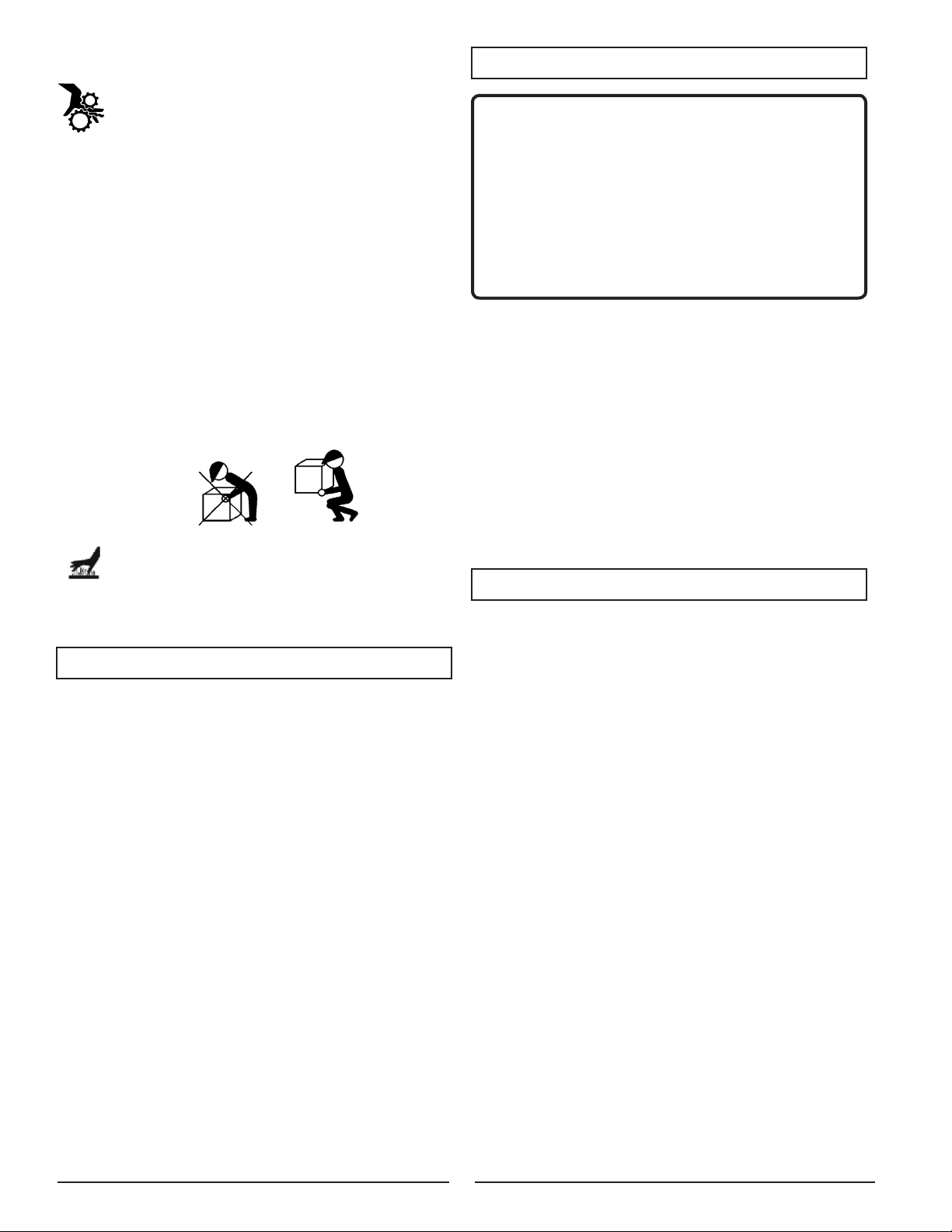
Use proper lifting techniques when transporting the
generator from site to site. Improper lifting techniques may result in personal injury.
To avoid burns, do not touch engine muffler or other
engine or generator surfaces which became hot during operation.
Do not alter or modify the heat shield.
SPARK ARRESTING MUFFLER
YOUR PRODUCT MAY NOT BE EQUIPPED WITH A
SPARK ARRESTING MUFFLER. If the product will be used
around flammable materials, such as agricultural crops, forests, brush, grass, or other similar items, then an approved
spark arrester should be installed and is legally required in the
State of California. The California statutes requiring a spark
arrester are Sections 13005(b), 4442 and 4443. Spark Arresters
are also required on some U.S. Forest Service land and may
also be legally required under other statutes and ordinances.
An approved spark arrester is available from our product
dealers, or may be ordered from Homelite Consumer Products, Inc., 1428 Pearman Dairy Road, Anderson, SC 29625,
1-800-242-4672.
OPERATING VOLTAGE
CAUTION:
Operating voltage and frequency requirement of all electronic
equipment should be checked prior to plugging them into this
generator. Damage may result if the equipment is not designed
to operate within a +/- 10% voltage variation, and +/- 3 hz
frequency variation from the generator name plate ratings. To
avoid damage, always have an additional load plugged into
the generator if solid state equipment (such as a television
set) is used. A power line conditioner is recommended for
some solid state applications.
A power line conditioner should be used when any of the
following solid state items:
Garage door openers
Kitchen appliances with digital displays
Televisions
Stereos
Personal computers
Quartz clocks
Copy machines
Telephone equipment
DETERMINING TOTAL WATTAGE
In order to prevent overloading and possible damage to
your generator it is necessary to know the total wattage of the
connected load. To determine which tools and/or appliances
your generator will run follow these steps:
Determine if you want to run one item or multiple items simul-
taneously.
Check wattage requirements for the items you will be running
by referring to the load’s nameplate or by calculating it (multiply amps x volts = watts).
Total the watts for each item. If the nameplate only gives volts
and amps, multiply volts x amps = watts.
1 KW = 1,000 watts
Motorized appliances or tools require more than their rated
wattage for start up.
NOTE: Allow 2-1/2 to 4 times the listed wattage for start
ing equipment powered by electric motors.
The generator’s rated watts should match or exceed the total
number of watts required for the equipment you want to run.
Always connect the heaviest load to the generator first, then
add other items one at a time.
-
4
Page 5
ELECTRICAL
GENERATOR CAPACITY
Make sure the generator can supply enough continuous
(running) and surge (starting) watts for the items you will
power at the same time. Follow these simple steps.
1. Selecttheitemsyouwillpoweratthesametime.
2. Total thecontinuous (running) wattsof theseitems. Thisis
the amount of power the generator must produce to keep the
items running. See the wattage reference chart at right.
3. Estimate how many surge (starting) watts you will need.
Surge wattage is the short burst of power needed to start
electric motor-driven tools or appliances such as a circular
saw or refrigerator. Because not all motors start at the same
time, total surge watts can be estimated by adding only the
item(s) with the highest additional surge watts to the total
rated watts from step 2.
Example:
Tool or Appliance
Window AC,
10,000 BTU
Continuous
(Running) Watts
1200 1800
Refrigerator 700 2200
1/3 HP Well Pump 1000 2000
27 in. Television 500 0
Light (75 Watts) 75 0
3475 Total
Running Watts
Total Continuous (Running) Watts 3475
Plus Highest Additional Surge Watts + 2200
Equals Total Generator Output Required 5675
POWER MANAGEMENT
To prolong the life of the generator and attached devices,
it is important to take care when adding electrical loads to
the generator. There should be nothing connected to the
generator outlets before starting its engine. The correct
and safe way to manage generator power is to sequentially
add loads as follows:
1. With nothing connected to the generator, start the engine as
described later in this manual.
2. Plug in and turn on the first load, preferably the largest load
you have.
3. Permit the generator output to stabilize (engine runs smoothly
and attached device operates properly).
4. Plug in and turn on the next load.
5. Again, permit the generator to stabilize.
6. Repeat steps 4 and 5 for each additional load.
Never add more loads than the generator capacity. Take
special care to consider surge loads in generator capacity
as previously described.
5
Surge
(Starting) Watts
2200 Highest
Surge Watts
CAUTION:
Do not overload the generator’s capacity. Exceeding the
generator’s wattage/amperage capacity can damage the
generator and/or electrical devices connected to it.
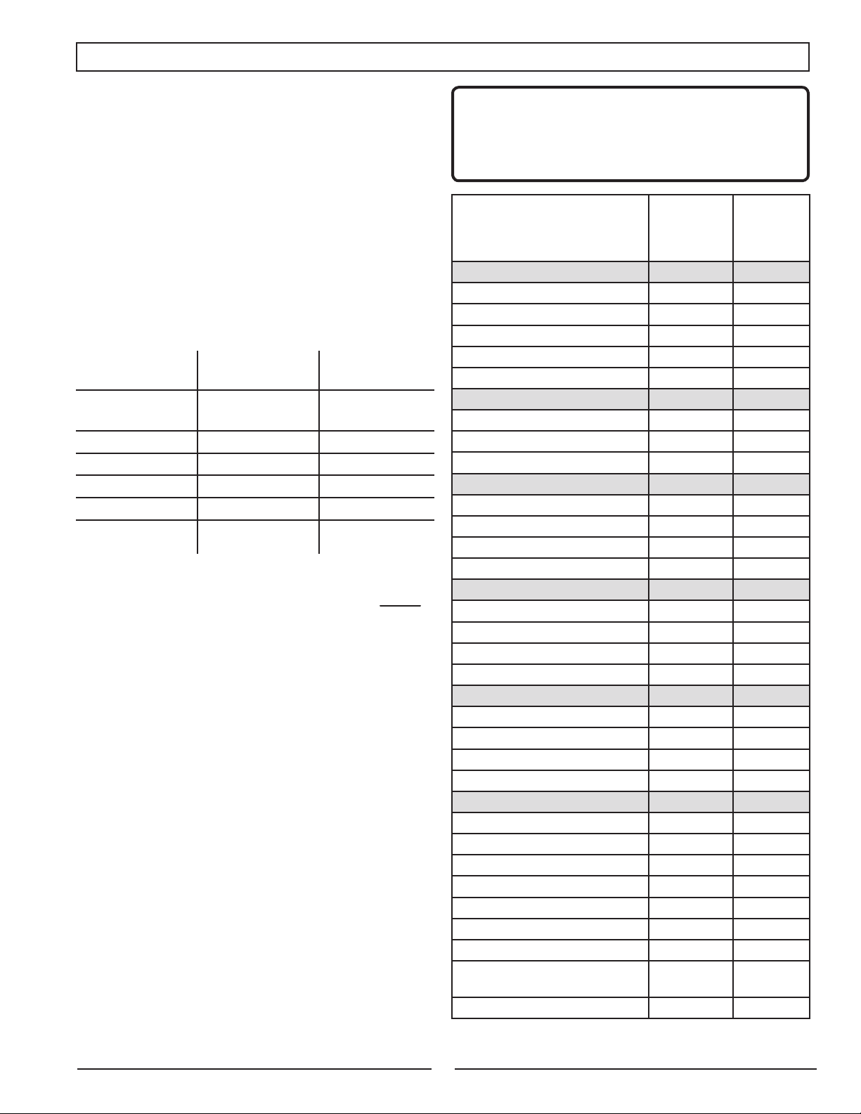
Typical
Tool or Appliance
Essentials
LightBulb−75Watt
Refrigerator/Freezer 700 2200
SumpPump−1/2HP
WaterWellPump−1/3HP
Electric Water Heater 4000 0
Heating/Cooling
FurnaceFan−1/2HP
WindowAC−10,000BTU
Space Heater 1800 0
Kitchen
MicrowaveOven−1000Watt
Coffee Maker 1000 0
ElectricStove−SingleElement
Toaster Oven 1200 0
Family Room
VCR 100 0
CD/DVD Player 100 0
Stereo Receiver 450 0
ColorTelevision−27in.
Other
Security System 500 0
Curling Iron 1500 0
GarageDoorOpener−1/2HP
HairDryer−1/2HP
DIY/Job Site
Quartz Halogen Work Light 1000 0
AirlessSprayer−1/3HP
Reciprocating Saw 960 0
ElectricDrill−1/2HP
CircularSaw−7-1/4in.
MiterSaw−10in.
Planer/Jointer−6in.
TableSaw/RadialArmSaw−
10 in.
AirCompressor−1HP
*Wattages listed are approximate. Check tool or appliance for actual wattage.
Continuous*
(Running)
Watts
75 75
1050 2200
1000 1500
800 2350
1200 1800
1000 0
2100 0
500 0
875 2350
1250 0
600 1200
600 900
1400 2300
1800 1800
1800 1800
2000 2000
1600 4500
Typical
Surge
(Starting)
Watts
Page 6

ELECTRICAL
EXTENSION CORD CABLE SIZE
Refer to the table below to ensure the cable size of the extension cords you use are capable of carrying the required
load. Inadequate size cables can cause a voltage drop, which can burn out the appliance and overheat the cord.
Current in
Amperes
2.5 300 600 1000 ft. 600 ft. 375 ft. 250 ft.
5 600 1200 500 ft. 300 ft. 200 ft. 125 ft.
7.5 900 1800 350 ft. 200 ft. 125 ft. 100 ft.
10 1200 2400 250 ft. 150 ft. 100 ft. 50 ft.
15 1800 3600 150 ft. 100 ft. 65 ft.
20 2400 4800 175 ft. 125 ft. 75 ft.
25 3000 6000 150 ft. 100 ft.
30 3600 7200 125 ft. 65 ft.
40 4800 9600 90 ft.
Load in Watts
At 120V At 240V #8 Wire #10 Wire #12 Wire #14 Wire #16 Wire
Maximum Allowable Cord Length
ELECTRIC MOTOR LOADS
It is characteristic of common electric motors in normal operation to draw up to six times their running current while
starting. This table may be used to estimate the watts required to start “Code G” electric motors; however, if an electric motor fails to start or reach running speed, turn off the appliance or tool immediately to avoid equipment damage.
Always check the requirements of the tool or appliance being used compared to the rated output of the generator.
Motor Size (H.P.) Running Watts
1/8 275 600 850 1200
1/6 275 600 850 2050
1/4 400 850 1050 2400
1/3 450 975 1350 2700
1/2 600 1300 1800 3600
3/4 850 1900 2600 —
1 1100 2500 3300 —
Repulsion Induction Capacitor Split Phase
Watts Required to Start Motor
6
Page 7
MAJOR GENERATOR FEATURES
Subaru OHC engine
Cast-iron cylinder sleeve
Receptacles on control panel
Cord retainer
4 gallon fuel tank
Spark arrester
Brushless generator
Portability Kit
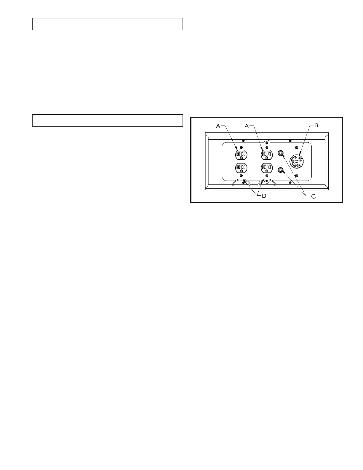
CONTROL PANEL
A. 120 V, 20 Ampere Duplex Receptacle
20 amps of current may be drawn from each half of the
receptacle. However, total power drawn must be kept within
nameplate ratings. These receptacles may be used along with
the twistlock receptacle provided the generator is not overloaded.
B. 120/240 V, 20 Ampere Twistlock Receptacle
A maximum of 20 amps may be drawn from the 120/240
volt receptacle, provided it is the only receptacle used. However,
current must be limited to the nameplate rating. If the 120/240
volt receptacle is used along with the 120 volt receptacle, the
total load drawn must not exceed the nameplate ratings.
C. Circuit Breakers
The receptacles are protected by an AC circuit breaker. If
the generator is overloaded or an external short circuit occurs,
the circuit breaker will trip. If this occurs, disconnect all electrical loads and try to determine the cause of the problem before
attempting to use the generator again. If overloading causes the
circuit breaker to trip, reduce the load. NOTE: Continuous trip-
ping of the circuit breaker may cause damage to generator
or equipment. The circuit breaker may be reset by pushing the
button of the breaker.
D. Cord Retainer
The cord retainer is used to prevent plugs from being pulled
out of the 120-volt receptacles.
7
Page 8

PORTABILITY KIT INSTALLATION
TOOLS REQUIRED: 7/16", 1/2" and 9/16" sockets and ratchets, block(s) of wood (minimum of 6" tall).
Refer to the parts list and drawing on pages 36-38.
WHEEL INSTALLATION
Block up end of generator opposite the fuel tank cap to install wheel kit.
Insert wheel spacer (item 43) into the center of the wheel (item 35).
Slide 3/8 x 4.25" bolt (item 41) and 3/8 washer (item 38) through the wheel (item 35), then through the wheel bracket on the
carrier, with the offset side of the wheel hub against the wheel bracket.
Thread 3/8 nyloc nut (item 42) onto the bolt and tighten to securely clamp the wheel assembly to the carrier.
Repeat above instructions for the remaining wheel.
FOOT INSTALLATION
Assemble the rubber feet (item 37) to the foot bracket (item 50) using a 1/4-20 x 1.5" bolt (item 48). Thread a 1/4 washer (item
49) and a 1/4 nyloc nut (item 13) to the bolt to secure the assembly. Caution: Do not over tighten so that the foot material
collapses.
Blocking up the alternator side of the generator, place the foot bracket under the carrier channel. Thread a 5/16-18 x 1" bolt (item
36) through the mounting holes and thread a 5/16 flange nut (item 15) to the bolt to secure the foot bracket to the carrier.
LOCKING HANDLE
Attach the lanyard (item 39) to the release pin
(item 44) and carrier as shown in the illustra-
tion.
To lock the handle (item 31) in the extended
position, align the holes in the handle bracket
with the holes in the carrier bracket and insert
the release pin (item 44).
Insert caps (item 45) into ends of handle (item
31).
1
2
8
Page 9
INSTALLATION
WARNING:
To avoid possible personal injury or equipment damage,
registered electrician or an authorized service representative
should perform installation and all service. Under no
circumstances should an unqualified person attempt to wire
into a utility circuit.
To avoid backfeeding into utility systems, isolation of the
residence electrical system is required.
Before temporary connection of the generator to the resi-
dence electrical system, turn off the main service/disconnect.
If your generator is to be used as a stand-by power source
in case of utility power failure, it should be installed by a registered electrician and in compliance with all applicable local
electrical codes.
Proper use requires that a double throw transfer switch be
installed by a licensed qualified electrician so that the building’s
electrical circuits may be safely switched between utility power
and the generator’s output, thereby preventing backfeed into
the power utility’s electrical system.
WARNING:
To avoid backfeeding into utility systems, isolation of the
residence electrical system is required. Before temporary
connection of a generator to the residence electrical system
turn off the main switch. Before making permanent connections
a double throw transfer switch To avoid electrocution or
property damage, only a trained electrician should connect
generator to residence electrical system. California law requires
isolation of the residence electrical system before connecting
a generator to residence electrical systems. Temporary
connection not recommended due to backfeeding.
BEFORE OPERATION
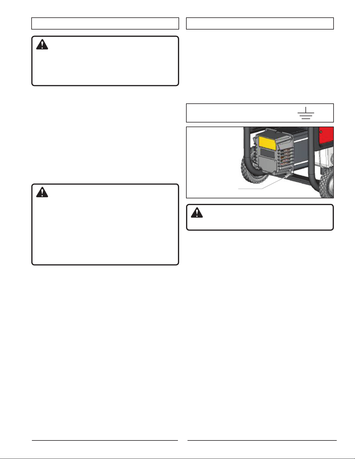
GROUNDING THE GENERATOR
The National Electric Code requires that this product be
properly connected to an appropriate earth ground to help prevent electric shock. A ground terminal connected to the frame
of the generator has been provided for this purpose. Connecting
a length of heavy gauge (12 AWG min.) copper wire between
the generator Ground Terminal and a copper rod driven into the
ground should provide a suitable ground connection. However,
consult with a local electrician to insure that local codes are
being adhered to.
GROUND TERMINAL LOCATION:
ground lug
WARNING:
Do not use a pipe as the ground source.
Always follow local codes and regulations that apply to
the installation of any item that concerns this product.
9
Page 10
LUBRICATION
DO NOT attempt to start this engine without filling the crank
case with the proper amount and type of lubricant. (See the
accompanying engine manual for this information.) Your generator has been shipped from the factory without lubricant in the
crankcase. Operating the unit without lubricant can damage the
engine.
Fill the engine with lubricant according to the engine manual. For units with a dipstick, fill lubricant to the proper level.
Units without a dipstick should be filled to the top of the opening
of the lubricant fill.
FUEL
Fill the tank with clean, fresh unleaded automotive gasoline.
Regular grade gasoline may be used provided a high octane
rating is obtained (at least 85 pump octane). We recommend
always using a fuel stabilizer. A fuel stabilizer will minimize the
formulation of fuel gum deposits during storage. The fuel stabilizer can be added to the gasoline in the fuel tank, or into the
gasoline in a storage container. Do not use E85 fuel.
CAUTION:
Do not overfill the tank. Keep maximum fuel level 1/4 inch
below the top of the fuel tank. This will allow expansion in
hot weather and prevent overflow.
STARTING THE UNIT
WARNING:
Gasoline is very dangerous. Serious injury or death can result
from fire caused by gasoline contacting hot surfaces.
Do not fill fuel tank with engine running.
Do not spill fuel while refilling tank.
Do not mix lubricant with gasoline.
Follow all instructions and warnings in the engine
manual.
PRE-START PREPARATION
Before starting the generator, check for loose or missing
parts and for any damage which may have occurred during
shipment.
WARNING:
This generator must not be operated without all factory installed
heat shields in place. Failure to comply may cause the fuel
tank to overheat and result in personal injury from fire.
STARTING THE ENGINE
Check lubricant level and fuel.
Disconnect all electrical loads from the unit.
Open fuel shut off valve.
Adjust choke as necessary.
Set the engine switch to the “ON” position.
Pull on the starter rope with fast steady pull. As the engine
warms up, readjust the choke.
DANGER:
Provide adequate ventilation for toxic exhaust gases and
cooling air flow.
Do not start or run the generator in an enclosed area, even
if door or windows are open.
Engines give off carbon monoxide, an odorless, colorless,
poison gas.
Breathing carbon monoxide can cause nausea, fainting
or death.
CAUTION:
Allow generator to run at no load for five minutes upon each
initial start-up to permit engine and generator to stabilize.
10
Page 11
APPLYING LOAD
This unit has been pretested and adjusted to handle its full
capacity. When starting the generator, disconnect all load. Apply
load only after generator is running. Voltage is regulated via the
engine speed adjusted at the factory for correct output. Readjusting will void warranty.
CAUTION:
When applying a load, do not exceed the maximum wattage
rating of the generator when using one or more receptacles.
Also, do not exceed the amperage rating of any one
receptacle.
SHUTTING THE GENERATOR OFF
Remove entire electrical load.
Let the engine run for a few minutes without load.
Move the engine switch to the “OFF” position.
Do not leave the generator until it has completely stopped.
Close the fuel shut off valve if the engine is to be put in stor-
age or transported.
If cover is used, do not install until unit has cooled.
BREAK-IN PROCEDURE
Controlled break-in helps insure proper engine and generator operation. Follow engine procedure outlined in engine
manual.
CAUTION:
Do not apply heavy electrical load during break-in period (the
first two to three hours of operations).
MAINTENANCE
GENERATOR: BRUSHES (BRUSH TYPE UNITS ONLY)
The brushes in the generator should be inspected once
every year for chips and cracks. Brushes should be replaced
when they are worn to 1/4 inch (7 mm).
NOTE: Replace brushes in sets only, never separately.
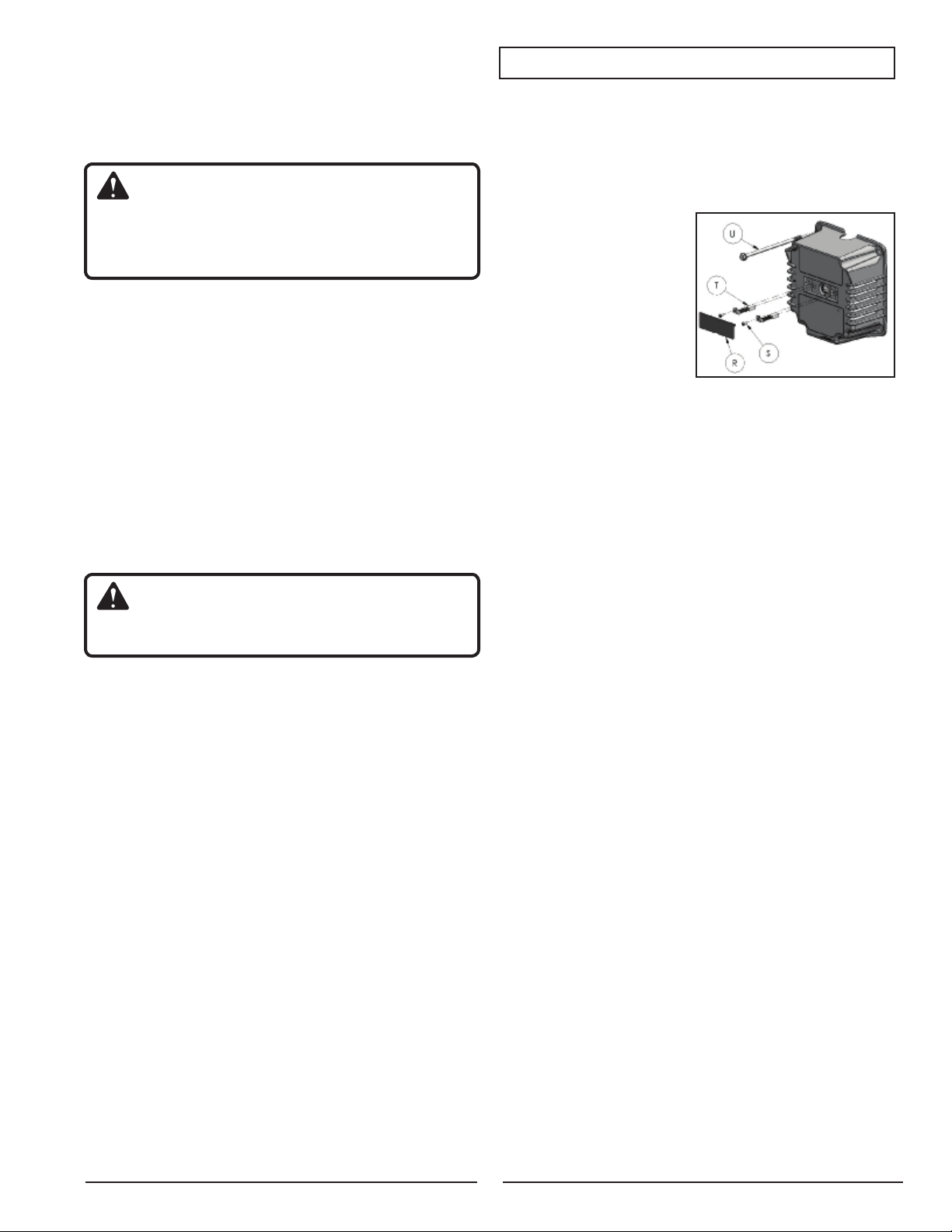
INSPECTING THE BRUSHES:
Remove cover plate (R).
Remove 4 stator bolts (U)
and endbell.
Remove screws holding
the protective plate on the
inside of the endbell.
Disconnect the green (–) or
blue (+) brush wires from
the tab.
Remove brush mounting screws (S).
Slide brushes (T) from holders.
Replace if worn to 1/4 inch (7mm).
Do not over tighten screws.
NOTE: Replace only with brushes specified in parts list.
Other brushes may appear to be identical but may have completely different mechanical and electrical characteristics.
HEAT SHIELD:
Inspect to ensure that all heat shields and heat deflectors
are intact and in place. Do not remove any parts or modify parts.
Removing or modifying parts could cause serious damage to
the unit.
ENGINE: Carburetor Icing
During the winter months, rare atmospheric conditions may
develop which will cause an icing condition in the carburetor. If
this develops, the engine may run rough, lose power, and may
stall.
QUICK STARTING TIPS FOR UNITS THAT HAVE BEEN
SITTING FOR AWHILE:
If your unit has been sitting around for a long time period
and is hard to start, try doing some of these easy steps before
calling Customer Service.
Check the lubricant level.
Replace the old fuel.
Change the spark plug.
Check the fuel lines. Make sure the fuel valve is open.
Check all generator parts for integrity.
Clean the carburetor. (See engine manual for service
centers)
11
Page 12

SERVICE AND STORAGE
LIMITED WARRANTY
INFREQUENT SERVICE
If the unit is used infrequently, difficult starting may result.
to eliminate hard starting, run the generator at least 30 minutes
every month. Also, if the unit will not be used for some time, it is
a good idea to drain the fuel from the carburetor and gas tank.
LONG TERM STORAGE
When the generator set is not being operated or is being
stored more than one month, follow these instructions:
Replenish engine lubricant to upper level.
Drain gasoline from fuel tank, fuel line and carburetor.
a) Turn the engine switch off ( O ).
b) Closefuelvalve.
c) Remove thefuel line fromthepetcock by squeezingthe
ends of the retaining clip and sliding the fuel line off.
d) Installoneendofadrainlineoverthepetcock,andplace
the other end in a fuel container large enough to catch the
fuel being drained from the tank.
e) Openfuelvalve.
f) When the fuelhas drainedfrom thetank, close thefuel
valve and reinstall fuel line on petcock.
Pour about one teaspoon of engine lubricant through the
spark plug hole, pull the recoil starter several times and
replace the plug. Then pull the starter until you feel the piston is on its compression stroke and leave it in that position.
This closes both the intake and exhaust valves to prevent the
inside of the cylinder from rusting.
Cover the unit and store in a clean, dry place that is well ven-
tilated away from open flame or sparks.
NOTE: We recommend always using a fuel stabilizer.
A fuel stabilizer will minimize the formulation of fuel gum
deposits during storage. The fuel stabilizer can be added to
the gasoline in the fuel tank, or into the gasoline in a storage
container.
WARRANTY COVERAGE
Homelite Consumer Products, Inc., (the Company) warrants to
the original retail purchaser that this Homelite Product is free from
defects in material and workmanship and agrees to repair or replace,
at the Company’s sole discretion, any defective Product free of
charge within these time periods from the date of purchase:
Two years, if the Product is used solely for personal, family, or
household use;
One year, if the Product is used for business or commercial use.
This warranty applies only to Products sold within the United States
of America, the District of Columbia, Canada, Mexico, the Commonwealth of Puerto Rico, the Virgin Islands, Guam, the Canal Zone, or
American Samoa.
This warranty is not transferable and does not cover damage resulting from defects other than in material or workmanship, or damage caused by unreasonable use, including the failure to provide
reasonable and necessary maintenance. Other items not covered
under this warranty include:
Transportation charges for sending the product to the Company
or its authorized service representative for warranty service, or
for shipping repaired or replacement products back to the cus-
tomer; these charges must be borne by the original retail pur-
chaser.
Engine. Your Product is equipped with an engine that is covered
exclusively by a separate warranty from the engine manufacturer.
Please refer to the engine manual included with the Product for
warranty information related to the engine.
Damages caused by abuse, accident, misuse, neglect, altera-
tion, modification, the effects of corrosion, erosion, normal wear
and tear or repairs by other than the Company or its authorized
service representative.
Warranty is voided if the customer fails to install, maintain and
operate the product in accordance with the instructions and
recommendations of the Company as set forth in the Product’s
operator’s manual or if the Product is used as rental equipment.
The Company will not pay for repairs or adjustments to the Prod-
uct, or for any costs or labor, performed without the Company’s
prior authorization.
SAVE YOUR SALES SLIP
Proof of purchase in the form of your dated sales receipt, cash register slip, etc. showing the serial number and the model of your Product will be required before the Company and/or its authorized service
representatives can perform warranty service on the Product.
EXCLUSIONS AND LIMITATIONS
THIS LIMITED WARRANTY IS IN LIEU OF ALL OTHER EXPRESS
WARRANTIES. ANY
ITY, FITNESS FOR A PARTICULAR PURPOSE, OR OTHERWISE,
APPLICABLE TO THIS PRODUCT, SHALL BE LIMITED IN DURATION TO THE DURATION OF THIS LIMITED WARRANTY. THE
WARRANTY SERVICE DESCRIBED ABOVE IS THE EXCLUSIVE
REMEDY UNDER THIS WARRANTY. THE COMPANY SHALL NOT
BE LIABILE FOR ANY SPECIAL, INCIDENTAL OR CONSEQUENTIAL DAMAGES.
SOME STATES DO NOT ALLOW A LIMITATION ON THE DURATION OF IMPLIED WARRANTIES, OR THE EXCLUSION OR LIMITATION OF INCIDENTAL, OR CONSEQUENTIAL DAMAGES, SO THE
ABOVE LIMITATION OR EXCLUSION MAY NOT APPLY TO YOU.
HOW TO OBTAIN WARRANTY SERVICE
For warranty service: Call toll free 1-800-242-7462, or write to
Homelite Consumer Products, Inc., 1428 Pearman Dairy Road,
Anderson, SC 29625.
For warranty service outside the USA, please contact your local
Homelite dealer.
IMPLIED WARRANTY OF MERCHANTABIL-
12
Page 13

SERVICE INFORMATION
CONTACT HOMELITE
CONSUMER PRODUCTS
CUSTOMER SERVICE AT
1-800-242-4672
or at
www.homelite.com
to obtain warranty service
information or to order
replacement parts or
accessories.
HOW TO ORDER REPLACEMENT PARTS
Even quality built equipment such as the electric generator
you have purchased, might need occasional replacement parts
to maintain it in good condition over the years. To order replacement parts, please give the following information:
Model No. and Serial No. and all specifications shown on the
Model No./Serial No. plate.
Part number or numbers as shown in the Parts List section of
the Insert for your generator model.
A brief description of the trouble with the generator.
NOTE: If replacement parts are required for the engine,
contact one of the engine manufacturer’s service centers.
Homelite Consumer Products, Inc.
1428 Pearman Dairy Road
Anderson, SC 29625
1-800-242-4672
www.homelite.com
LIMITED 3-YEAR ENGINE WARRANTY
Limited Manufacturer’s Warranty from Subaru Robin
(Effective with engines purchased from Robin America, Wood Dale, IL,
after April 1, 2008)
Robin America, Inc., a division of Fuji Heavy Industries, Ltd. (herein
“Subaru Robin”), warrants that each new engine sold by it will be free,
under normal use and service, from defects in material and workmanship for a period listed below from the date of sale to the original retail
purchaser. Subaru Robin’s obligation under this Limited Warranty shall
be limited to the repair and replacement, at Subaru Robin’s option, of
any part or parts which upon examination is/are found, in Subaru Robin’s judgment, to have been defective in material or workmanship. It shall
be a condition of Subaru Robin’s obligation under this Limited Warranty
that Subaru Robin, directly or through one of its Distributors or Service
Centers authorized to service the particular engine involved, receive
prompt notice of any warranty claim and that the engine or the part
or parts claimed to be defective be promptly delivered, transportation
prepaid, to such Distributor or Service Center for inspection and repair.
13
All repairs qualifying under this Limited Warranty must be performed by
Subaru Robin or one of its authorized Distributors or Service Centers.
WARRANTY PERIODS:
Subaru Robin Four-Cycle, Air-cooled, Gasoline Engines - Limited 3
YEAR Warranty (EX / EH Series 4.3hp or greater)
The repair or replacement of any part or parts under this Limited Warranty shall not extend the term of the engine warranty beyond the original term as set forth above.
LIMITATIONS AND EXCLUSIONS: This Limited Warranty shall not apply
to:
Bent or broken crankshaft or resultant damage caused by vibration
related to a bent or broken crankshaft. Also, damage caused by
loose engine mounting bolts or improper or imbalanced accessories
or blades mounted to the crankshaft.
Repairs required because of prolonged storage including damage
caused by old or contaminated fuel in the fuel tank, fuel lines or carburetor, sticky valves or corrosion and rust of engine parts.
Repair required due to overheating. (Most often caused by over-
loaded or clogged or damaged or missing flywheel, fan, inlet air passages, cooling fins or air shrouds).
Dirt or grit related wear caused by improper air cleaner maintenance
(most often resulting in worn piston, piston rings, cylinders, valves,
valve guides, carburetor or other internal components).
Broken or scored parts caused by low lubricant level, dirty or
improper grade of lubricant.
Engine tune-ups and normal maintenance service including, but not
limited to, valve adjustment, normal replacement of service items,
fuel and lubricant, etc.
Any engine which has been subject to negligence, misuse, accident,
mis-application or over-speeding.
Any engine that has been installed, repaired, or altered by anyone in
a manner which in Subaru Robin’s sole judgment adversely affects
its performance or reliability.
Any engine which has been fitted with or repaired with parts or com-
ponents not manufactured or approved by Subaru Robin which in
Subaru Robin’s sole judgment adversely affects its performance or
reliability.
Instances when normal use has exhausted the life of a component or
an engine.
The customer is responsible for all transportation charges in connection
with any warranty work.
Subaru Robin reserves the right to modify, alter or improve any engines
or parts without incurring any obligation to modify or replace, any
engine or parts previously sold without such modification, alternation
or improvement.
No person is authorized to give any other warranty or to assume any
additional obligation on Subaru Robin’s behalf unless made in writing
and signed by an officer of Subaru Robin.
Some states do not allow limitations on how long an implied warranty
lasts or the exclusion or limitation of incidental or consequential damages, so the above limitation(s) or exclusion(s) may not apply to you.
This warranty gives you specific legal rights and you may also have other
legal rights which vary from state to state.
THIS WARRANTY, AND SUBARU ROBIN’S OBLIGATION HERE UNDER,
ARE IN LIEU OF ANY OTHER WARRANTIES OR OBLIGATIONS OF
ANY KIND, EXPRESSED OR IMPLIED, INCLUDING ANY WARRANTIES OF MERCHANTABILITY OR FITNESS FOR A PARTICULAR PURPOSE. THERE ARE NO WARRANTIES WHICH EXTEND BEYOND THE
DESCRIPTION ON THE FACE HERE-OF. SUBARU ROBIN SHALL IN NO
EVENT BE LIABLE FOR ANY CONSEQUENTIAL OR INCIDENTAL DAMAGES.
Page 14

SÉCURITÉ
DANGER :
DANGER signifie une situation
susceptible de présenter un danger
qui, s’il n’est pas évité, CAUSERA de
sérieuses blessures, voire la mort.
AVERTISSEMENT :
L’AVERTISSEMENT indique une
situation présentant un danger potentiel
et qui, en l’absence d’intervention,
pourrait conduire à la mort ou entraîner
de graves blessures.
RÈGLES D’OPÉRATION ET DE SÉCURITÉ
AVERTISSEMENT :
L’inobservation des présentes consignes et l’ignorance des
avertisse ments qui en découlent risquent de causer des
blessures et des dommages ou d’entraîner la mort.
Lire attentivement le guide d’utilisation et le manuel
de fonctionnement du moteur, puis s’assurer de les
comprendre avant de mettre l’appareil en marche.
Observer l’ensemble des avertissements et des
directives s’y rapportant.
Se familiariser avec l’appareil et tenir compte des
domaines d’usage, des restrictions et des risques
potentiels qui découlent de son utilisation.
On doit placer l’équipement sur un support plat et
solide.
La charge doit être dans les normesspécifiées sur
la plaque signalétique de l’appareil. Toute surcharge
abîme l’appareil et en raccourcit la durée de vie utile.
Le moteur ne doit pas tourner à des vitesses
excessives car ceci augmente les risques de
blessures personnelles. Ne touchez pas aux pièces
ce qui pourrait augmenter ou réduire la vitesse
régulée.
Afin d’empêcher les démarrages imprévus, toujours
enlever la bougie ou le câble de la bougie avant
d’ajuster le groupe électrogène ou le moteur.
Un appareil dont les pièces sont cassées, auquel il
manque des pièces ou qui n’a pas de carter ou de
coquille protectrice ne doit en aucun cas être utilisé.
Contacter notre service après-vente pour des pièces
de rechange.
Ne pas faire fonctionner ou entreposer l’appareil
dans un endroit humide ni sur une surface mouillée,
ni dans un endroit où il sera en contact avec des
surfaces conductrices telles que des planchers ou
armatures métalliques.
Garder l’appareil propre et libre de toute huile, boue
ou autre matière étrangère.
Les rallonges, les cordons d’alimentation et tout
appareil électrique doivent être en bon état. Ne
jamais faire fonctionner un appareil électrique dont
le cordon d’alimentation est abîmé ou défectueux.
Rangez le nettoyeur haute pression dans un endroit
bien ventilé, réservoir d’essence vide. On ne doit pas
ranger l’essence près du groupe électrogène.
Vous ne devez jamais utiliser votre appareil sous ces
conditions:
ATTENTION :
La mention ATTENTION sert à prévenir
l’utilisateur d’un danger potentiel qui
risque d’occasionner des dommages ou
des blessures légères ou modérées.
a. Modification irrépressible du régime moteur. (NOTA
fonction optionnelle de commande de ralenti per met de
réduire le régime moteur à l’état “sans charge”).
b. Perte de puissance électrique.
c. Surchauffe d’appareils connectés.
d. Jaillissement d’étincelles.
e. Prises endommagées.
f. Le moteur a des ratés.
g. Vibrations excessives.
h. Flammes ou fumée.
i. Compartiment fermé.
j. Temps mauvais ou pluvieux. Éviter d’exposer l’ap pareil à
l’humidité en cours de fonctionnement.
Vérifiez le système de carburant régulièrement pour toute
fuite ou signes de détérioration tels un tuyau spongieux ou
usé, une bride qui manque ou desserrée ou un réservoir ou
couvercle endommagé. On doit corriger ces problèmes avant
de faire fonctionner l’appareil.
Le fonctionnement, l’entretien et le ravitaillement en carburant
de l’appareil ne doivent se faire que dans les conditions
suivantes :
a. Faites démarrer et fonctionner la génératrice à l’extérieur.
Ne faites jamais fonctionner la génératrice dans un endroit
clos, même si les portes et les fenêtres sont ouvertes.
Évitez les endroits où les vapeurs peuvent être enfermées,
comme des fosses, des garages, des caves, des excava-
tions et des fonds de cale de bateau.
: La
DANGER :
RISQUE D’ÉMISSION DE MONOXYDE DE
CARBONE :
du monoxyde de carbone, un gaz toxique, inodore
et invisible qui, s’il est respiré, peut causer de
sérieuses blessures, voire la mort. Si vous ne vous sentez
pas bien, êtes pris d’étourdissement ou vous sentez faible
en utilisant la génératrice, mettez-la hors tension et respirez
de l’air frais immédiatement car vous souffrez peut-être d’un
empoisonnement au monoxyde de carbone.
b. Bonne aération pour le refroidissement. Le débit d’air
et la température sont importants pour les systèmes
à refroidissement à air. La température ne devrait pas
dépasser 104°F (40°C).
c. Refaites le plein du groupe électrogène dans un endroit
bien éclairé. Évitez les débordements de carburant et ne
refaites jamais le plein lorsque l’appareil est en marche.
L’échappement des moteurs contient
14
Page 15

d. Ne faites pas le plein près de flammes nues, de
veilleuses ou d’équipement électrique projetant
des étincelles comme les outils électriques, les
soudeuses et les meuleuses.
e. Le silencieux et le filtre à air doivent toujours être
en place et en bon état puisqu’ils jouent le rôle de
coupe-flammes s’il y a des ratés.
f. Ne pas fumer près du générateur.
S’assurer que l’appareil est correctement posé sur
le sol. (Voir la section «Mise en place de l’appareil»
dans le présent manuel.)
Ne portez pas de vêtements amples, de bijoux ou
toute autre chose qui pourrait se prendre dans le
démarreur ou autres pièces rotatives.
L’appareil doit atteindre son régime de fonctionnement
avant que toute charge y soit connectée. Débrancher
toute charge avant d’arrêter le moteur.
Afin d’empêcher les pointes de tension qui
pourraient endommager les appareils branchés sur
la génératrice, ne pas laisser le moteur tomber en
panne de carburant pendant que des appareils sont
branchés dessus.
Lorsque vous utilisez de l’équipement en solide,
vous devriez utiliser un protecteur de surtension
pour éviter d’endommager l’équipement.
Ne rien mettre dans les fentes d’aération, même
quand l’appareil n’est pas en marche. Ceci pourrait
l’abîmer ou provoquer des blessures.
Avant de transporter la génératrice dans un véhicule,
le vider de tout carburant afin d’empêcher les
fuites.
Pour transporter l’appareil d’un site à l’autre, utilisez
les bonnes techniques de levage sinon vous pourriez
vous blesser.
VÉRIFIER LA TENSION
ATTENTION :
Vérifier la tension et la fréquence requises avant de brancher
tout équipement électronique sur le générateur. Le générateur
peut se trouver endommagé si les appareils branchés ne
sont pas prévus pour fonctionner à une tension égale à ±
10% et une fréquence égale à ± 3 hz de celles indiquées
sur la plaque signalétique du générateur. Pour éviter tout
dommage, toujours brancher une charge additionnelle sur
le générateur lorsqu’un appareil à circuits intégrés (tel qu’un
téléviseur) est utilisé. Une varistance peut être aussi nécessaire
pour certaines applications, dans le cas d’un ordinateur, par
exemple. Une varistance peut être aussi nécessaire pour
certaines applications de l’équipement en solide.
Il est préférable d’utiliser un filtre de secteur lors de la
mise en fonction d’un ou de plusieurs des composants à
semiconducteurs suivants:
Ouvres-portes de garage
Appareils de cuisine à affichage digital
Téléviseurs
Stéréos
Ordinateurs personnel
Pendules à quartz
Machines à photocopier
Équipement téléphonique
DÉTERMINATION DE LA PUISSANCE
TOTALE NÉCESSAIRE
Pour éviter les brûlures, ne touchez pas au
silencieux du moteur ou à toute autre surface du
moteur ou du générateur qui se réchauffe durant le
fonctionnement.
Ne modifiez pas l’écran de chaleur.
PARE-ÉTINCELLES
VOTRE PRODUIT PEUT NE PAS ÊTRE MUNI D’UN
SILENCIEUX PARE-ÉTINCELLES. S’il doit être utilisé à proximité
de matériaux inflammables tels que récoltes, forêts, broussailles,
herbes ou autres, il est fortement recommandé d’installer un
pare-étincelles, par ailleurs obligatoire en Californie. Les articles
de la loi californienne relatifs à l’usage de pare-étincelles sont les
suivants : 13005(b), 4442 et 4443. L’usage d’un pare-étincelles
est également exigé sur certains des territoires du service des
Forêts américain et peut également l’être par d’autres lois et
règlements. Un pare-étincelles homologué est disponible auprès
de notre concessionnaires ou peut être commandé à Homelite
Consumer Products, Inc., 1428 Pearman Dairy Rd., Anderson,
SC 29625, Téléphone : 1-800-242-4672.
Afin d’éviter à la génératrice la surcharge et les dommages
possibles, il faut connaître la puissance totale de la charge
branchée. Pour déterminer quels outils et/ou quels appareils
peuvent fonctionner avec votre générateur, suivez ces étapes :
Déterminez si vous désirez faire fonctionner un ou plusieurs
appareils simultanément.
Vérifiez les exigences normales pour démarrer et faire
fonctionner les appareils voulus en vous reportant à la plaque
signalétique de charge ou en effectuant ce calcul (multipliez
les ampères x volts = watts).
Additionnez le nombre de watts de démarrage et
de fonctionnement de chaque appareil. Toutefois, la
plaque signalétique de l’équipement vous donnera des
chiffres de consommation d’électricité plus exacts.
Si la plaque ne vous donne que des volts et des
ampères, multipliez les volts par les ampères = watts.
1KW = 1 000 watts.
Les appareils ou les outils à moteur exigent plus que leur
puissance indiquée pour le démarrage.
REMARQUE : Prévoir 2 1/2 - 4 fois la puissance indiquée
pour la mise en marche de l’appareil.
La puissance nominale du générateur devrait être égale
ou supérieure au nombre total de watts nécessaires au
fonctionnement de l’équipement à alimenter.
Branchez toujours d’abord la charge la plus lourde au
générateur, puis ajoutez les les autres une à une.
15
Page 16

CARACTÉRISTIQUES ÉLECTRIQUES
CAPACITÉ DU GÉNÉRATEUR
S’assurer que le générateur peut fournir les watts continus (de
fonctionnement) et de surtension (démarrage) suffisants pour
tous les articles alimentés au même moment. Suivre ces simples
étapes.
1. Sélectionner les articles qui seront alimentés au même
moment.
2. Faireletotaldeswattscontinus(defonctionnement)deces
articles. Ceci correspond à la somme de puissance que
le générateur doit produire pour que ces articles puissent
fonctionner. Voir le tableau de référence de wattage à droite.
3. Déterminerleswattsdesurtension(démarrage)nécessaires.
Les watts de surtension correspondent à la courte pointe de
puissance nécessaire pour démarrer les outils ou les appareils
à moteur électriques, tels que les scies circulaires ou les
réfrigérateurs. Les moteurs ne démarrant pas tous au même
moment, le total des watts de surtension peut être déterminé
en ajoutant uniquement les articles au wattage de surtension
supplémentaire le plus élevé au wattage nominal total de
l’étape 2.
Exemple :
Watts de
Outil ou appareil
Climatiseur de
fenêtre, 10 000 BTU
Réfrigérateur 700 2200
Pompe de puits
1/2 ch
Télévision de 27
pouces
Éclairage (75 W) 75 0
Wattage continu (fonctionnement) total 3475
Plus wattage de surtension
supplémentaire maximum + 2200
Égal à la sortie totale du générateur requise 5675
fonctionnement
(continu)
1200 1800
1000 2000
500 0
3475 Wattage
de fonctionnement
total
Watts de
surtension
(démarrage)
2200 Wattage
de surtension
maximum
GESTION DE L’ÉNERGIE
Pour prolonger la durée de vie du générateur et des appareils
reliés, il est important d’effectuer l’ajout de charges électriques
supplémentaires au générateur avec soin. Rien ne doit être
connecté aux sorties du générateur avant le démarrage du moteur.
Une gestion correcte et en toute sécurité de l’énergie du générateur
consiste à ajouter des charges en séquence :
1. Sans appareil connecté au générateur, mettre le moteur en
marche de la façon décrite dans ce manuel.
2. Brancher et mettre en marche la première charge, de préférence
la plus importante.
3. Laisser la sortie du générateur se stabiliser (le moteur tourne
régulièrement et l’appareil relié fonctionne correctement).
4. Brancher et mettre la charge suivante en marche.
5. Une fois de plus, laisser le générateur se stabiliser.
6. Rép é t er les ét a p es 4 et 5 pour chaque c h arge
supplémentaire.
Ne jamais ajouter de charges supérieures à la capacité du
générateur. Bien veiller à considérer les charges de surtension
comme décrit précédemment.
16
ATTENTION :
Ne pas surcharger la capacité du générateur. Le dépassement
de la capacité du wattage/de l’ampérage du générateur peut
endommager le générateur et/ou les appareils électriques qui
lui sont reliés.
Watts
de fonc-
Outil ou appareil
Appareils courants
Ampoule−75watts
Réfrigérateur/congélateur 700 2200
Pompedevidange−1/2ch
Pompedepuits−1/3ch
Chauffe-eau électrique 4000 0
Chauffage/climatisation
Ventilateur de générateur d’air
chaud−1/2ch
Climatiseur de fenêtre - 10 000 BTU
Radiateur d’appoint 1800 0
Cuisine
Micro-ondes - 1000 watts 1000 0
Machine à café 1000 0
Cuisinière électrique - réchaud
unique
Grille-pain four 1200 0
Salle familiale
Magnétoscope 100 0
Lecteur de CD/DVD 100 0
Récepteur stéréo 450 0
Télévisioncouleur−27pouces
Autre
Système de sécurité 500 0
Fer à cheveux 1500 0
Télécommande d’ouvre-porte de
garage - 1/2 ch
Sèche-cheveux−1/2ch
Site de travail/atelier
Lampe de travail quartz-halogène 1000 0
Pulvérisateursansair−1/3ch
Scie alternative
Perceuseélectrique−1/2ch
Sciecirculaire−185mm(7-1/4po)
Scieàonglet−255mm(10po)
Raboteuse/dégauchisseuse−152
mm (6 po)
Scie circulaire à table/scie circulaire
tous azimuts - 255 mm (10 po)
Compresseur à air - 1 ch 1600 4500
*Les wattages indiqués sont approximatifs. Vérifier le wattage
sur l’outil ou l’appareil.
tionnement
continus
typiques*
75 75
1050 2200
1000 1500
800 2350
1200 1800
2100 0
500 0
875 2350
1250 0
600 1200
960 0
600 900
1400 2300
1800 1800
1800 1800
2000 2000
Watts de
surtension (démarrage)
typiques
Page 17

CARACTÉRISTIQUES ÉLECTRIQUES
TAILLE DU CÂBLE DU CORDON PROLONGATEUR
Voir le tableau ci-dessous pour vérifier que la taille de câble des cordons prolongateurs utilisés est capable de porter la charge
requise. Des tailles de câbles inadéquates peuvent causer une chute de tension qui peut griller l’appareil et surchauffer le cordon.
Courant
en
ampères
2.5 300 600 305 m (1000 pieds) 183 m (600 pieds) 114 m (375 pieds) 76 m (250 pieds)
5 600 1200 152 m (500 pieds) 91 m (300 pieds) 61 m (200 pieds) 38 m (125 pieds)
7.5 900 1800 107 m (350 pieds) 61 m (200 pieds) 38 m (125 pieds) 31 m (100 pieds)
10 1200 2400 76 m (250 pieds) 46 m (150 pieds) 31 m (100 pieds) 15 m (50 pieds)
15 1800 3600 46 m (150 pieds) 31 m (100 pieds) 20 m (65 pieds)
20 2400 4800 53 m (175 pieds) 38 m (125 pieds) 23 m (75 pieds)
25 3000 6000 46 m (150 pieds) 31 m (100 pieds)
30 3600 7200 38 m (125 pieds) 20 m (65 pieds)
40 4800 9600 27 m (90 pieds)
Charge en
watts
À
120 V
À
240 V
Fil de
calibre 8
Longueur de cordon permise maximum
Fil de
calibre 10
Fil de
calibre 12
Fil de
calibre 14
Fil de
calibre 16
CHARGES DU MOTEUR ÉLECTRIQUE
Les moteurs électriques courants en fonctionnement normal tirent jusqu’à six fois leur courant de fonctionnement lors du démarrage.
Ce tableau peut être utilisé pour estimer les watts requis pour démarrer les moteurs électriques « code G » ; cependant, si un moteur
électrique ne démarre pas ou n’atteint pas sa vitesse de fonctionnement, éteindre immédiatement l’appareil ou l’outil pour éviter
d’endommager l’équipement. Toujours vérifier les exigences de l’outil ou de l’appareil utilisé par rapport à la sortie nominale du
générateur.
Taille du
moteur (ch)
1/8 275 600 850 1200
1/6 275 600 850 2050
1/4 400 850 1050 2400
1/3 450 975 1350 2700
1/2 600 1300 1800 3600
3/4 850 1900 2600 —
1 1100 2500 3300 —
Watts de
fonctionnement
Répulsion Induction Condensateur Phase auxiliaire
Watts requis pour le démarrage du moteur
17
Page 18

CARACTÉRISTIQUES PRINCIPALES
DU GROUPE ELECTROGENE
Moteur Subaru OHC
Chemise de cylindres en fonte
Prises sur tableau de commande
Retenue de cordon
Réservoir de carburant d’une contenance de 15.1 litres
(4 gallons)
Pare-étincelles
Sans balais génératrice
Kit de transport
TABLEAU DE COMMANDE
A. Prise double de 120 V, 20 A
20 ampères de courant peuvent être dessinés de chaque
moitié de la prise. La charge totale doit cependant rester dans
les limites indiquées sur la plaque signalétique. Ces prises
peuvent s’utiliser en conjonction avec la prise à verrouillage à
condition que le générateur ne soit pas surchargée.
C. Disjoncteurs
Les prises sont protégées par un disjoncteur alternatif. En
cas de surcharge ou de court-circuit extérieur, le disjoncteur
saute. Si cela se produit, débrancher tout appareil relié au groupe
électrogène et essayer de déterminer la cause du problème
avant d’essayer de le réutiliser. Si le disjoncteur saute en raison
d’une surcharge, réduire la charge. REMARQUE : Le groupe
électrogène ou les appareils branchés dessus peuvent se
trouver abîmés si le disjoncteur saute continuellement.
Appuyer sur le bouton du disjoncteur pour le réenclencher.
D. Retenue de cordon
Le retenue de cordon est un dispositif qui empêche la fiche
de ressortir accidentellement d’une prise de 120 volts.
B. Prise à verrouillage de 120/240 V, 20 A
Cette prise de 120/240 V fournit un maximum de 20 A à
condition que ce soit la seule utilisée. La charge totale doit
par ailleurs rester dans les limites indiquées sur la plaque
signalétique. Si la prise de 120/240 V est utilisée en conjonction
avec les prises de 120 V, la charge totale ne doit pas dépasser
les limites indiquées sur la plaque.
18
Page 19

L’INSTALLATION DE KIT DE TRANSPORT
OUTILS NÉCESSAIRES : Cliquet à rochet de 7/16 po, 1/2 po, et 9/16 po, blocs de bois (minimum de 6 po de hauteur)
Reportez-vous à la liste des pièces et au dessin des pages 36 à 38.
INSTALLATION DES ROUES
Faire reposer l’extrémité de la génératrice à l’opposé de celle où se trouve le capuchon du réservoir d’essence sur un bloc de
façon à pouvoir effectuer la pose de la roue.
Insérer une bague d’espacement (article 43) dans le centre de la roue (article 35).
Enfiler le boulon de 3/8 x 4.25 po (article 41) et rondelle de 3/8 po (article 38) dans la roue (article 35), puis dans le support de la
roue sur le transporteur, en le plaçant de façon à ce que le côté le plus en creux du moyeu de la roue repose contre le support.
Enfiler l’écrou à frein élastique de 3/8 po (article 42) sur le boulon et serrer de façon à bien fixer la roue sur la transporteur.
Procéder de la même façon pour l’autre roue.
INSTALLATION DU PIED
Monter le pied (article 37) sur le support de pied (article 50) au moyen d’un boulon de 1/4-20 x 1.5 po (article 48). Fixer
l’ensemble en vissant sur le boulon un écrou nyloc (article 13), avec une rondelle (article 49). Attention : ne pas trop serrer,
pour ne pas écraser le matériau du pied.
En bloquant le côté alternateur de la génératrice, mettre en place le support de pied sous
le profilé en U. Visser un boulon de 5/16-18 x 1 po (article 36) dans les trous de fixation,
puis visser sur le boulon un écrou bride de 5/16 po (article 15), pour fixer le support de
pied au profilé.
POIGNEE VERROUILLANT
Attacher le lanyard (article 39) à l’épingle de relâchement (article 44) et le transporteur
selon l’illustration.
Pour verrouiller la poignée (article 31) dans la position étendue, aligner les trous dans le
support de poignée avec les trous dans le support de transporteur et insérer l’épingle de
relâchement (article 44).
L’insertion capuchon (article 45) dans les fins de poignée (article 31).
1
2
19
19
Page 20

INSTALLATION
AVERTISSEMENT :
Pour éviter toute blessure et tout dommage aux appareils, faire
effectuer l’installation électrique et toutes réparations par un
électricien licencié ou un specialiste du service après-vente
agréé. En aucune circonstance, une personne non qualifiée
ne doit-elle essayer de réaliser le câblage sur l’installation
électrique existante.
Pour éviter les retours de courant dans l’installation électrique
de la maison, il est nécessaire d’assurer son isolation.
Avant de procéder au raccordement temporaire du
générateur au système électrique de la résidence, débrancher
le sectionneur du réseau d’alimentation principal.
Si du générateur est utilisée comme source auxiliaire en cas
de panne de courant, il doit être installé par un électricien qualifié
et en conformité avec tous les codes locaux applicables.
Pour que l’installation soit correcte, un commutateur de
transfert à deux directions doit être installé par un électricien
qualifié et licencié de façon à ce que les circuits électriques du
bâtiment puissent être commutés du secteur au générateur sans
danger, empêchant ainsi les retours de courant dans le secteur.
AVERTISSEMENT :
Pour éviter les retours de courant dans le secteur, il est
nécessaire d’assurer l’isolation électrique de la maison.
Avant d’effectuer la connexion temporaire du générateur
sur l’installation électrique de la maison, couper le courant
à l’interrupteur principal. Avant de réaliser des connexions
permanentes, installer un commutateur de transfert à deux
directions. Pour éviter toute électrocution ou des dommages
matériels, faire connecter le générateur à l’installation électrique
de la maison par un électricien qualifié. Les lois californiennes
exigent l’isolation de l’installation électrique de la maison avant
d’y connecter un groupe électrogène. Il n’est pas recommandé
de procéder au raccordement temporaire de l’appareil en
raison de la réalimentation.
AVANT DE METTRE EN MARCHE
MISE EN PLACE DE L’APPAREIL
Selon les recommandations stipulées dans le Code national
de l’électricité, cet appareil doit faire l’objet d’un raccordement
adéquat à une prise de terre afin de prévenir tout risque
d’électrocution. Une borne de mise à la terre connecté au bâti
du générateur est prévue à cet effet. Le branchement d’un fil de
cuivre de fort calibre (AWG 12 minimum) et de bonne longueur
entre la borne de mise à la terre du générateur et un fil machine
en cuivre enfoncé dans cette dernière devrait fournir une bonne
mise à la terre. Consulter néanmoins un électricien agréé afin de
vous assurer que le tout est conforme aux codes locaux.
L’EMPLACEMENT DE BORNE
DE MIS À TERRE:
Borne de mise
à terre
AVERTISSEMENT :
Ne pas utiliser une conduite comme source de mise à la
terre.
Toujours observer les codes et règlements locaux qui
s’appliquent à l’installation de tout appareil compatible avec
ce produit.
20
Page 21

LUBRIFICATION
NE PAS essayer de faire démarrer le moteur avant d’avoir
rempli le carter de lubrifiant, en utilisant la quantité et le type de
lubrifiant appropriés. (Ces renseignements sont fournis dans le
manuel du moteur ci-inclus.) Le groupe électrogène est expédié
de l’usine avec le carter vide. Un moteur qui tourne sans huile
dans le carter peut se trouver détruit.
Remplir le moteur de lubrifiant selon les directives énoncées
dans le manuel de fonctionnement du moteur. Dans le cas des
appareils dotés d’une jauge de lubrifiant, remplir au niveau
adéquat. Les appareils qui en sont dépourvus doivent faire l’objet
d’un remplissage jusqu’à l’ouverture supérieure du goulot.
CARBURANT
Remplir le réservoir d’essence automobile sans plomb
fraîche et libre de toute impureté. De l’essence ordinaire peut
être utilisée, à condition qu’elle ait un indice d’octane élevé (85
octane minimum). Il est recommandé d’utiliser en tout temps
le stabilisateur de carburant, ce qui permettra de réduire la
formation de dépôts de gomme dans le carburant lors de son
entreposage. On peut ajouter le stabilisateur à l’essence en le
versant soit dans le réservoir de carburant, soit dans un récipient
d’entreposage. Ne pas utiliser le carburant E85.
DEMARRAGE DE L’APPAREIL
AVERTISSEMENT :
L’essence est un produit très dangereux. Un incendie résultant
du contact de l’essence avec des surfaces chaudes peut
causer de graves blessures ou entraîner la mort.
Ne pas mettre de l’essence dans le réservoir quand le
moteur est en marche.
Ne pas renverser d’essence lors du remplissage du
réservoir.
Ne pas mélanger de l’huile à l’essence.
Nous vous invitons aussi à respecter les consignes et les
avertissements énoncés dans le manuel de fonctionnement
du moteur.
PRÉPARATIFS AU DÉMARRAGE
Avant de mettre l’appareil en marche, vérifier qu’il ne
manque aucune pièce, que toutes les pièces sont bien serrées
et que l’appareil n’a pas été abîmée pendant le transport.
ATTENTION :
Ne pas trop remplir le réservoir. Maintenir le niveau d’essence
maximum à un centimètre au-dessous du haut du réservoir.
Ceci permet l’expansion du carburant pendant les périodes
de chaleur et empêche l’essence de déborder.
AVERTISSEMENT :
Ne pas faire fonctionner ce groupe électrogène sans les écrans
de chaleur montés en usine en place. Le non-respect de cette
consigne peut entraîner la surchauffe du réservoir de carburant
et des blessures à la suite de l’incendie ainsi provoqué.
DÉMARRAGE DU MOTEUR
Vérifiez le niveau de lubrifiant et de carburant.
Débranchez toutes les charges électriques de l’appareil.
Ouvrez la vanne de fermeture de carburant.
Réglez le doseur au besoin.
Réglez l’interrupteur du moteur en position “ON”.
Tirez sur la corde de lancement d’un coup rapide et sûr.
Lorsque le moteur se réchauffe, réglez à nouveau le doseur.
DANGER :
Fournir une aération suffisante pour éliminer les gaz
d’échappement toxiques et assurer le refroidissement du
moteur.
Ne pas faire démarrer ou fonctionner l’appareil dans un
lieu fermé, même si les portes et les fenêtres sont grandes
ouvertes.
Les moteurs libèrent du monoxyde de carbone, un gaz
invisible, inodore et toxique.
L’inhalation de monoxyde de carbone peut provoquer des
nausées, des évanouissements ou même la mort.
21
Page 22

ATTENTION :
Laisser le groupe électrogène fonctionner cinq minutes sans
aucun appareil branché dessus au moment du démarrage
initial pour permettre au moteur et au groupe électrogène de
se stabiliser.
BRANCHEMENT DES APPAREILS
Cet appareil a été vérifié et réglé pour fonctionner à pleine
capacité. Débrancher tout appareil qui y est relié avant de le
mettre en marche. Attendre qu’il tourne avant de commencer
à brancher des appareils dessus. La tension est réglée par la
vitesse du moteur, qui a été ajustée à l’usine pour assurer la
puissance voulue. Le rajustement annulera la garantie.
ATTENTION :
Ne pas dépasser la puissance nominale du générateur
lorsqu’une ou plusiers prises sont utilisées. De plus, ne pas
dépasser l’ampérage nominal d’une prise, quelle qu’elle
soit.
ARRET DE L’APPAREIL
Retirez toute la charge électrique.
Laissez le moteur tourner quelques minutes sans charge.
Placez l’interrupteur du moteur en position “OFF”.
Ne quittez pas le générateur jusqu’à ce qu’il soit complètement
arrêté.
Fermez la vanne de fermeture du carburant (s’il y en a une) si
le moteur doit être rangé ou transporté.
Si l’on utilise, un couvercle, ne l’installez pas jusqu’à ce que
l’appareil soit refroidi.
RODAGE
Un rodage bien mené aide à assurer le bon fonctionnement
du moteur et du groupe électrogène. Suivre les recommandations
données dans le manuel du moteur.
ENTRETIEN
GROUPE ELECTROGENE: Les Balais (LES UNITES DE TYPE
DE BROSSE SEULEMENT)
Les balais du groupe électrogène doivent être inspectés une
fois par an pour vérifier s’ils ne sont pas fendillés ou autrement
abîmés. Il faut par ailleurs les remplacer quand ils ne font plus
que 7 mm.
Remarque : Toujours remplacer le jeu de balais et non
pas un seul balai à la fois.
INSPECTION DES BALAIS:
Enlever la plaque (R).
Enlever les 4 boulons du
stator (U) et le couvreenroulement.
Enlever les vis retenant
la tôle protectrice logée
à l’intérieur du flasque
d’extrémité.
Déconnecter les fils verts (–) ou bleus (+) des balais de la
patte.
Enlever les vis de montage des balais (S).
Faire glisser les balais (T) des porte-balais.
Remplacer les balais s’ils ne font plus que 7 mm.
Ne pas trop resserrer les vis.
REMARQUE : Remplacer les balais uniquement avec
les balais de rechange spécifiés dans la liste des pièces
détachées. D’autres balais peuvent paraître identiques
mais avoir des caractéristiques mécaniques et électriques
complètement différentes.
ÉCRANS DE CHALEUR :
Vérifier que tous les écrans de chaleur et les déflecteurs
thermiques sont intacts et en place. Ne pas procéder à
l’enlèvement ou à la modification des pièces, puisque cela
risquerait d’occasionner de graves dommages à l’appareil.
ATTENTION :
Ne pas brancher un appareil puissant sur le générateur pendant
la période de rodage (les deux à trois premières heures de
fonctionnement).
22
GIVRAGE DU CARBURATEUR
Pendant les mois d’hiver, des conditions atmosphériques
rares peuvent provoquer la formation de glace dans le
carburateur. Quand cela arrive, le moteur fonctionne mal, perd
de sa puissance et peut même tomber en panne. Ce problème
temporaire peut être corrigé en faisant souffler l’air chaud du
moteur sur le carburateur. Pour de plus amples renseignements,
contacter le service clientèle.
TRUCS DE DÉMARRAGE RAPIDE DES APPAREILS RESTÉS
LONGTEMPS HORS FONCTION:
Si votre appareil est resté longtemps hors fonction et que son
démarrage s’avère difficile, suivre les quelques étapes suivantes
avant de recourir à l’assistance téléphonique à la clientèle.
Vérifier le niveau de lubrifiant.
Faire une vidange de carburant complète.
Remplacer les bougies d’allumage.
Vérifier les canalisations de carburant et veiller à ce que le
robinet à essence soit ouvert.
Vérifier les pièces du groupe électrogène afin de vous assurer
de leur intégrité.
Nettoyer le carburateur (voir le manuel de fonctionnement du
moteur pour connaître l’adresse des centres de réparation).
Page 23

USAGE ET ENTREPOSAGE
GARANTIE LIMITÉE
USAGE PEU FRÉQUENT
Si la génératrice est rarement utilisée, il est possible qu’elle
soit difficile à mettre en marche. Pour éliminer ce problème, faire
tourner la génératrice pendant au moins 30 minutes toutes les
semaines. Par ailleurs, si elle ne doit pas être utilisée pendant un
certain temps, il est bon de vider le carburateur et le réservoir
de toute essence.
ENTREPOSAGE A LONG TERME
Si le groupe électrogène n’est pas utilisé ou qu’il est remisé
pendant plus d’un mois, procéder comme suit :
Remettre de le lubrifiant jusqu’au repère supérieur.
Éliminer toute essence du réservoir, de la conduite et du
carburateur.
a) Mettre le contacteur du moteur sur arrêt ( O ).
b) Fermerlerobinetdecarburant.
c) Retirerlaconduitedecarburantdupetitrobinetenserrant
les extrémités de l’attache et en glissant la conduite pour
la retirer.
d) Installeruneextrémitédutuyaudevidangesurlerobinet
et placer l’autre extrémité dans un récipient suffisamment
large pour contenir le carburant vidangé.
e) Ouvrirlerobinetdecarburant.
f) Lorsque le carburantest vidangédu réservoir,fermer le
robinet de carburant et réinstaller la conduite sur le petit
robinet.
Mettre environ une cuillerée à café de lubrifiant pour moteur
dans l’orifice des bougies, tirer sur le lanceur à plusieurs
reprises et remettre la bougie en place. Ensuite, tirer sur
le lanceur jusqu’à ce que le piston soit en position de
compression et le laisser dans cette position. Ceci ferme les
soupapes d’admission et d’échappement afin d’empêcher
l’intérieur du cylindre de rouiller.
Couvrir l’appareil et l’entreposer dans un endroit propre, sec
et bien aéré, loin de toute source de flamme ou d’étincelles.
REMARQUE : Il est recommandé d’utiliser en tout temps
le stabilisateur de carburant, ce qui permettra de réduire la
formation de dépôts de gomme dans le carburant lors de
son entreposage. On peut ajouter le stabilisateur à l’essence
en le versant soit dans le réservoir de carburant, soit dans
un récipient d’entreposage.
23
COUVERTURE DE LA GARANTIE
Homelite Consumer Products, Inc. (l’entreprise) garantit à l’acheteur
original au détail que ce produit de marque Homelite est exempt de tout
vice de matériau ou de fabrication et s’engage à réparer ou remplacer,
à discrétion, tout produit s’avérant défectueux au cours des périodes
indiquées ci dessous, à compter de la date d’achat :
Deux ans sur les produits utilisés uniquement par des particuliers;
Un an sur les produits à des fins d’utilisation professionnelle ou
commerciale.
Cette garantie s’applique uniquement aux produits vendus aux ÉtatsUnis, dans le district fédéral de Columbia, au Canada, au Mexique, à
Puerto Rico, dans les îles Vierges, à Guam, dans la zone du canal de
Panama ou en Samoa américaine.
Cette garantie n’est pas transférable et ne couvre pas les dommages
attribuables à des vices autres que les vices de matériau ou de
fabrication, ou les dommages liés à une utilisation abusive, ce qui
inclut l’omission de faire subir au produit un entretien raisonnable. Les
éléments suivants ne sont pas couverts par la garantie :
Les frais de transport requis pour envoyer le produit à l’entreprise
ou à son représentant autorisé du service à la clientèle en vue de
procéder à l’entretien sous garantie du produit, ou pour réexpédier le
produit au client à la suite de sa réparation ou de son remplacement.
Il incombe à l’acheteur original d’assumer ces frais.
Le moteur. Ce produit comprend un moteur qui est couvert
exclusivement par une garantie distincte de son fabricant. Veuillez
consulter le manuel du moteur fourni avec le produit pour trouver des
renseignements sur la garantie du moteur.
Les dommages attribuables à une utilisation abusive, à un accident,
à une mauvaise utilisation, à de la négligence, à une modification,
aux effets de la corrosion ou de l’érosion, à l’usure normale ou à
des réparations effectuées par quiconque autre que le personnel de
l’entreprise ou de son représentant autorisé du service à la clientèle.
La garantie est considérée comme nulle si le produit n’est pas
installé, entretenu et utilisé conformément aux instructions et aux
recommandations de l’entreprise, qui sont décrites dans le manuel
d’utilisation du produit. La garantie s’annule également si le produit
est utilisé à des fins de location.
L’entreprise n’assumera en aucun cas les frais liés à la réparation ou
à l’ajustement du produit, ou les coûts associés à des tâches pour
lesquelles elle n’a pas donné son consentement.
CONSERVER LES FACTURES
Une preuve d’achat sous la forme d’un reçu de vente ou de caisse daté
sur lequel sont indiqués les numéros de série et de modèle du produit est
requise pour que l’entreprise ou ses représentants autorisés du service
à la clientèle puissent procéder à l’entretien sous garantie du produit.
EXCLUSIONS ET LIMITES
CETTE GARANTIE LIMITÉE REMPLACE TOUTES LES AUTRES
GARANTIES EXPRESSES. LA DURÉE DE TOUTE GARANTIE
IMPLICITE DE QUALITÉ MARCHANDE, DE QUALITÉ DE CONVENANCE
À DES FINS PARTICULIÈRES OU DE TOUT AUTRE COUVERTURE
APPLICABLE À CE PRODUIT NE PEUT EXCÉDER LA DURÉE DE LA
PRÉSENTE GARANTIE. L’ENTRETIEN SOUS GARANTIE DÉCRIT
PRÉCÉDEMMENT CONSTITUE LE SEUL RECOURS PRÉVU AUX
TERMES DE LA GARANTIE. L’ENTREPRISE NE PEUT ÊTRE TENUE
RESPONSABLE POUR AUCUN DOMMAGE SPÉCIAL, INDIRECT OU
CONSÉCUTIF.
CERTAINS ÉTATS ET CERTAINES PROVINCES NE PERMETTENT
PAS D’EXONÉRATION OU DE RÉSERVE POUR CE QUI EST DE LA
COUVERTURE DES DOMMAGES DIRECTS OU CONSÉCUTIFS ET DE
LA DURÉE DE TOUTE GARANTIE IMPLICITE; IL SE PEUT DONC QUE
L’EXONÉRATION PRÉCÉDENTE NE PUISSE S’APPLIQUER.
COMMENT BÉNÉFICIER D’UN ENTRETIEN SOUS GARANTIE
Pour bénéficier d’un entretien sous garantie, composer sans frais
le 1 800 242 7462 ou communiquer par écrit à l’adresse suivante
: Homelite Consumer Products, Inc., 1428 Pearman Dairy Road,
Anderson, SC 29625.
Pour bénéficier d’un entretien sous garantie à l’extérieur des États
Unis, veuillez communiquer avec le concessionnaire local des
produits Homelite.
Page 24

SERVICE CLIENTELE
CONTACTER HOMELITE
CONSUMER PRODUCTS
SERVICE CLIENTELE
À
1-800-242-4672
ou à
www.homelite.com
pour obtenir des renseignements
sur les modalités de réparation
sous garantie ou pour
commander des pièces ou des
accessoires de rechange.
COMMANDE DE PIÈCES DE RECHANGE
Même dans le cas d’appareils de haute qualité comme le
groupe électrogène en votre possession, des pièces de rechange
peuvent devenir nécessaires pour garder l’appareil en bon état
au fur et à mesure que passent les années. Pour commander
des pièces de rechange, veuillez fournir les renseignements
suivants :
Les numéros de modèle et de série ainsi que toutes les
spécifications portées sur la plaque où sont indiqués les
numéros de modèle et de série.
Les codes de pièces apparaissent dans la section
Nomenclature des pièces de rechange de l’annexe
correspondant au modèle de votre appareil.
Une brève description du problème rencontré.
REMARQUE : Si des pièces de rechange sont nécessaires
pour le moteur, contacter l’un des centres de service aprèsvente du fabricant.
Homelite Consumer Products, Inc.
1428 Pearman Dairy Road
Anderson, SC 29625
1-800-242-4672
www.homelite.com
GARANTIE LIMITÉE DE TROIS ANS
SUR LE MOTEUR
Garantie limitée de Subaru Robin
(Applicable aux moteurs achetés de Robin America à Wood Dale, IL,
après le 1 avril 2008)
Robin America, Inc., une division de Fuji Heavy Industries, Ltd. (désigné ciaprès « Subaru Robin »), garantit à l’acheteur original que chaque nouveau
moteur qui est vendu est exempt de tout vice de matériau ou de fabrication
pendant la période indiquée ci dessous (à partir de la date d’achat) dans
des conditions normales d’utilisation et sous condition d’un entretien
normal. Dans le cadre de cette garantie limitée, Subaru Robin contracte une
obligation envers sa clientèle qui se limite à la réparation ou au remplacement
(au choix de l’entreprise) de toute pièce jugée, après évaluation de Subaru
Robin, comme présentant des vices de matériau ou de fabrication. Toutefois,
aux termes de cette garantie, l’obligation imposée à Subaru Robin est limitée
par une condition selon laquelle l’entreprise, ou l’un de ses distributeurs ou
de ses centres de réparations agréés autorisés à procéder à l’entretien du
moteur, doit recevoir la réclamation au titre de la garantie ou la pièce ou les
24
pièces défectueuses en temps opportun, avec les frais de transport payés
au préalable, pour effectuer une inspection et une réparation. Toutes les
demandes de réparation qui respectent les conditions de la garantie limitée
doivent être traitées par Subaru Robin ou par l’un de ses distributeurs ou de
ses centres de réparations agréés.
PÉRIODES DE GARANTIE :
Moteurs à essence à quatre temps, refroidis à l’air de Subaru Robin
– garantie limitée de 3 ANS (séries EX et EH 4.3ch ou plus grand)
Tel que mentionné précédemment, la réparation ou le remplacement de toute
pièce en application de cette garantie limitée ne doit pas s’étendre au delà
des termes d’origine de la garantie sur le moteur.
LIMITES ET EXCLUSIONS : Cette garantie limitée ne s’applique pas aux
éléments suivants :
Un vilebrequin courbé ou brisé, ou tout dommage résultant d’une
vibration causée par la courbure ou le bris du vilebrequin. Tout dommage
attribuable à des boulons de montage desserrés sur le moteur, à
l’utilisation d’accessoires inadéquats ou déséquilibrés, ou à l’installation
de lames sur le vilebrequin.
Les réparations requises en raison d’un entreposage prolongé, ce qui
inclut les dommages causés par le carburant usé ou contaminé contenu
dans le réservoir, la canalisation d’essence et le carburateur; les valves
poisseuses, et la corrosion et la rouille des pièces du moteur.
Les réparations requises en raison d’une surchauffe (le plus souvent
causée lorsqu’un volant, un ventilateur, une entrée d’air, une ailette de
refroidissement ou une grille de prise d’air sont surchargés, bouchés,
manquants ou endommagés).
L’usure liée à la poussière ou au sable et causée par l’entretien inadéquat
du purificateur d’air (se traduisant le plus souvent par l’usure des pistons,
des segments de piston, des cylindres, des soupapes, des guides de
soupape, du carburateur ou d’autres composants internes).
Les pièces brisées ou rayées en raison du bas niveau de lubrifiant ou de
l’utilisation de lubrifiant usagée ou de calibre inadéquat.
La mise au point du moteur ou tout entretien normal, y compris, mais non
de façon limitative, le réglage des soupapes, le remplacement normal des
pièces, du carburant, de le lubrifiant, etc.
Toute défectuosité du moteur attribuable à la négligence, à une mauvaise
utilisation, à un accident ou à l’emballement.
Toute installation, réparation ou modification du moteur qui, selon Suburu
Robin, nuit à son rendement ou à sa fiabilité.
Toute installation ou réparation du moteur effectuée à l’aide de pièces
ou de composants qui n’ont pas été fabriqués ou approuvés par Subaru
Robin. L’entreprise est libre de juger si les pièces ou les composants en
question nuisent au rendement ou à la fiabilité du moteur.
Toute situation où un composant ou un moteur est totalement usé en
dépit d’une utilisation normale.
Le client doit assumer tous les frais de transport liés aux travaux relatifs aux
garanties.
Subaru Robin se réserve le droit de modifier ou d’améliorer tous les moteurs
et les pièces sans contracter l’obligation de modifier ou de remplacer les
moteurs et les pièces vendus avant la mise en œuvre de ces modifications
ou de ces améliorations.
Nul n’est autorisé à offrir une garantie supplémentaire ou à assumer d’autres
obligations au nom de Subaru Robin, à moins qu’une preuve écrite signée
par un agent de l’entreprise ne soit présentée.
Certains états permettent pas d’exonération ou de réserve pour ce qui est de
la couverture des dommages directs ou consécutifs et de la durée de toute
garantie implicite; il se peut donc que l’exonération décrite précédemment ne
puisse s’appliquer. La présente garantie donne au consommateur des droits
spécifiques, et celui ci peut bénéficier d’autres droits, qui varient selon les
états ou provinces.
LA PRÉSENTE GARANTIE AINSI QUE L’OBLIGATION DE SUBARU
ROBIN DÉCRITE AUX PRÉSENTES REMPLACENT TOUTES LES AUTRES
GARANTIES OU OBLIGATIONS, EXPRESSES OU IMPLICITES, CE QUI
INCLUT TOUTE GARANTIE DE QUALITÉ MARCHANDE OU DE QUALITÉ
DE CONVENANCE À DES FINS PARTICULIÈRES. AUCUNE GARANTIE NE
VA AU DELÀ DE LA DESCRIPTION FOURNIE AUX PRÉSENTES. SUBARU
ROBIN NE PEUT EN AUCUN CAS ÊTRE TENU RESPONSABLE POUR TOUT
DOMMAGE DIRECT OU INDIRECT.
Page 25

SEGURIDAD
PELIGRO:
PELIGRO indic a una situ a c i ón
potencialmente peligrosa que, si no
se evita, PROVOCARÁ muerte o una
lesión seria.
ADVERTENCIA:
ADVERTENCIA indica una situación de
peligro potencial, la cual, si no se evita,
podría ocasionar lesiones severas e
incluso la muerte.
REGLAS DE SEGURIDAD Y DE FUNCIONAMIENTO
ADVERTENCIA:
El no seguir estas instrucciones y advertencias puede ocasionar
la muerte, heridas personales o daños materiales.
Lea cuidadosamente y entienda el manual del operador
antes de utilizar este producto. Lea y entienda el
manual del motor antes de su funcionamiento. Siga
todas las advertencias e instrucciones.
Conozca su equipo. Considere las aplicaciones,
limitaciones y los riesgos potenciales específicos de
su unidad.
El equipo deberá colocarse sobre una base de
sustentación firme.
La carga debe mantenerse dentro de los valores
nominales que aparecen en la placa de identificación
del generador. Una sobrecarga dañará la unidad o
acortará su vida útil.
No se debe hacer funcionar el motor a velocidades
demasiado altas. Si se opera el motor a excesiva
velocidad aumenta el riesgo de lesiones físicas. No
toque o cambie piezas que puedan aumentar o
disminuirla velocidad regulada.
Para evitar un arranque inesperado, siempre retire la
bujía o el cable de la bujía antes de dar mantenimiento
al generador o al motor.
Nunca debe operarse una unidad con piezas
quebradas o faltantes, o sin el revestimiento o
cubiertas protectoras. Comuniquese con su centro
de servicio para solicitar los repuestos.
Las unidades no deben operarse ni almacenarse
en lugares húmedos o mojados ni altamente
conductores tales como plataformas metálicas o
estructuras de acero.
Mantenga el generador limpio y libre de aceite, barro
y cualquier otro material extraño.
Los cordones de extensión, los cordones eléctricos y
todos los equipos eléctricos deben estar en buenas
condiciones. Nunca opere un equipo eléctrico con
cordones dañados o defectuosos.
Guarde el generador en un lugar con buena
ventilación, con el tanque de combustible vacío.
No se debe almacenar combustible cerca del
generador.
Su generador no deberá operarse jamás si ocurre do
lo siguiente:
25
PRECAUCIÓN:
PRECAUCIÓN indica una situación
potencialmente de riesgo, la cual, si
no se evita, puede ocasionar heridas
personales menores o moderadas o
daños materiales.
a. Cambio fuera de control en la velocidad del motor. (NOTA:
la característica opcional control en descanso reducirá la
velocidad del motor a una condición “Sin carga”).
b. Pérdida de carga eléctrica.
c. Sobrecalentamiento del equipo conectado.
d. Formación de chispas.
e. Receptáculos dañados.
f. Fallo de encendido.
g. Vibración excesiva.
h. Llamas o humo.
i. Compartimiento cerrado.
j. Lluvia o inclemencia del tiempo. No permita que la unidad
se moje cuando está funcionando.
Verifique periódicamente que no haya salideros o señales
de deterioro en el sistema de combustible, como manguera
demasiado gastada o blanda, abrazaderas flojas o faltantes,
o tanque o tapón dañados. Todos estos defectos deberán
corregirse antes de la operación.
El generador debe operarse, recibir servicio y rellenarse de
combustible solamente en las siguientes condiciones:
a. Encienda y ponga a funcionar el generador al aire libre. No
ponga a funcionar el generador en un área cerrada, aun
cuando las puertas o ventanas se encuentren abiertas;
evite áreas en donde los vapores puedan encerrarse, tales
como pozos, garajes, sótanos, excavaciones y pantoques.
PELIGRO:
RIESGO DE MONÓXIDO DE CARBONO: El escape
del motor contiene monóxido de carbono, un gas
venenoso, inodoro, invisible que, si se inhala puede
provocar la muerte o una lesión personal seria. Si
comienza a sentirse indispuesto, mareado o débil mientras
uti liza el generador, apáguelo e inmediatamente vaya a un
lugar fresco; podría padecer de envenenamiento por monóxido
de carbono.
b. Buena ventilación para el enfriamiento. La circulación de
aire y las temperaturas son importantes para las unidades
enfriadas por aire. Las temperaturas no deberían exceder
104°F (40°C) a temperatura ambiente.
c. Eche combustible al generador en un área bien iluminada.
Evite derramamiento de combustible y nunca rellene con
combustible mientras el generador está funcionando.
Antes de echar combustible, espere que el motor se enfríe
durante dos minutos.
d. No eche combustible cerca de llamas, luces piloto o
equipos eléctricos con chispas como herramientas
mecánicas, soldadores y rectificadoras.
Page 26

e. Deberá instalar el silenciador y filtro de aire, los
cuales deberán estar buenas condiciones en
todo momento ya que detienen el fuego en caso
de una explosión incompleta en el motor.
f. No fume cerca del generador.
Cerciórese de el generador esté conectado a tierra
correctamente (Consulte la sección Conexión a
tierra del generador).
No use ropa demasiado holgada, alhajas o cualquier
otra cosa que pueda quedar atrapada en el
arrancador u otras partes movibles.
La unidad debe alcanzar la velocidad de operación
antes de conectarse las cargas eléctricas.
Desconecte las cargas antes de apagar el motor.
Para evitar sobrecargas que podrían dañar al equipo,
no permita que el motor se quede sin combustible al
aplicarse las cargas eléctricas.
Al dar carga a un equipo de estado sólido, debe
utilizarse un protector de sobrecarga para evitar
posibles daños al equipo.
No coloque nada a través de las ranuras de
ventilación, aun cuando el generador no esté en
operación. Esto puede dañar al generador o causar
lesiones personales.
Antes de transportar el generador en un vehículo,
extraiga todo el combustible para evitar la posibilidad
de salideros o derrames.
Use técnicas correctas de alzaje al mover el
generador de un lugar a otro. De lo contrario, podrían
producirse lesiones personales.
EL REQUERIMIENTO DE VOLTAJE
PRECAUCIÓN:
El requerimiento de voltaje y frecuencia operativa de todos los
equipos electrónicos debe comprobarse antes de enchufarlos
a este generador. Pueden ocurrir daños si el equipo no está
diseñado para operar dentro de una variación de voltaje
de +/-10% y una variación de frecuencia de +/-3 hz de los
valores nominales que aparecen en la placa de identificación
del generador. A fin de evitar daños, siempre tenga una carga
adicional enchufada al generador en caso de usarse equipos
de estado sólido (tales como un aparato de televisión).
También podría resultar necesario un condicionador de la
línea eléctrica para algunas aplicaciones; por ejemplo, con
una computadora. También podria resultar necesario un
condicionador de la línea eléctrica para algunas aplicaciones
de equipo de estado sólido.
Se deberá utilizar un acondicinador de línea de conducción
cuando se operen uno o más de los siguientes equipos de
estado sólido:
Control para abrir la cochera o garaje
Equipos de cocina con visualización digital
Televisores
Estéreos
Computadoras personales
Relojes de cuarzo
Máquinas fotocopiadoras
Equipo telefónico
Para evitar quemaduras, no toque el silenciador
del motor u otras superficies del generador que se
hayan calentado durante la operación.
No modifique el escudo contra el calor.
APAGACHISPAS
PUEDE SER QUE SU PRODUCTO NO ESTE EQUIPADO
CON UN SILENCIADOR APAGACHISPAS. Si el producto se va
a utilizar cerca de materiales inflamables como son cosechas
agrícolas, bosques, arbustos, pastos, etc., debe entonces
instalarse un apagachispas adecuado. Esto es obligatorio
en el estado de California, de acuerdo con las secciones de
estatutos 13005(b), 4442 y 4443. Los apagachispas son
también obligatorios en algunas tierras del Servicio Forestal de
los EE.UU. y quizá también según otros estatutos u ordenanzas
legales. Existen apagachispas de uso aprobado en nuestro
distribuidors. También puede encargarse a Homelite Consumer
Products, Inc., 1428 Pearman Dairy Rd., Anderson, SC 29625,
EE.UU., teléfono 1-800-242-4572.
COMO DETERMINAR
EL VATAJE TOTAL
A fin de evitar la sobrecarga y los posibles daños a su
generador, resulta necesario conocer el vataje total de la carga
conectada. Para determinar qué herramientas y/o equipos
electrodomésticos su generador hará funcionar, siga los pasos
a continuación:
Determine sí desea hacer funcionar un aparato o varios
aparatos simultáneamente.
Verifque los requerimientos de potencia de arranque y
de funcionamiento de los aparatos fijándose en las carga
especificada en la etiqueta, o calculándola (multiplique
amperios x voltios = watts o potencia).
Sume la potencia necesaria de arranque y de funcionamiento
de cada aparato. Sí la etiqueta sólo le da el voltaje y el
amperaje, entonces multiplique Voltios x Amperios = Watts.
1KW = 1,000 watts.
Los electrodomésticos o herramientas impulsadas por
motores requieren más potencia que lo especificado para
arrancar.
NOTA: Permita 2 1/2 - 4 veces el vataje mencionado para
arrancar al equipo.
Los vatios unitarios del generador deberían coincidir o
superar el número total de vatios que requiere el equipo que
usted desea arrancar.
Siempre conecte la carga más grande primero, y luego
agregue los demás equipos uno por uno.
26
Page 27

ASPECTOS ELÉCTRICOS
CAPACIDAD DEL GENERADOR
Cerciórese que el generador pueda suministrar suficientes vatios
de potencia continua (en marcha) y de sobrecorriente (al arrancar)
para los equipos que desee alimentar al mismo tiempo. Siga
estos pasos sencillos.
1. Seleccione los equipos que desea alimentar al mismo
tiempo.
2. Sume lapotencia continua(enmarcha) en vatiosde estos
equipos. Esta es la cantidad de potencia que el generador
debe producir para mantener en marcha los equipos. Observe
la tabla de referencia de potencia en vatios, a la derecha.
3. Calculecuántapotenciainicial(alarranque)envatiosnecesitará.
La potencia inicial (en vatios) es la breve variación rápida
de potencia necesaria para poner en marcha los aparatos
o herramientas accionados con motor eléctrico como las
sierras circulares o los refrigeradores. Debido a que no todos
los motores arrancan al mismo tiempo, se puede calcular
la potencia inicial total en vatios sumando sólo los equipos
con el mayor valor de potencia inicial adicional a la potencia
nominal del paso 2.
Ejemplo:
Herramienta o
aparato
Acondicionador de
aire de ventana,
10000 BTU
Refrigerador 700 2200
Bomba de pozo de
1/3 HP
Televisor de 27 pulg 500 0
Iluminación (75 vatios)
Potencia continua total en vatios (en marcha) 3475
Potencia inicial adicional máxima en vatios + 2200
Potencia total de salida requerida del generador 5675
Potencia continua
(en marcha) en
vatios
1200 1800
1000 2000
75 0
3475 vatios,
potencia en
marcha total
Potencia inicial
(arranque) en
vatios
2200 vatios,
potencia inicial
máxima
ADMINISTRACIÓN DE LA POTENCIA
A fin de prolongar la vida útil del generador y los dispositivos
acoplados, es importante tener cuidado al agregar cargas eléctricas al generador. NO debe haber equipo alguno conectado a
los tomacorrientes del generador antes de poner en marcha el
motor respectivo. La manera correcta y segura de administrar la
potencia del generador consiste en agregar las cargas de manera
secuencial de la manera siguiente:
1. Sin equipos conectados al generador, ponga en marcha el
motor de la manera que se describe posteriormente en este
manual.
2. Enchufe y active la primera carga, preferiblemente la máxima
carga que tenga.
3. Deje que se estabilice la salida del generador (el motor
marcha uniformemente y el dispositivo acoplado funciona
correctamente).
4. Enchufe y active la siguiente carga.
5. Nuevamente, deje que el generador se estabilice.
6. Repita los pasos 4 y 5 para cada carga adicional.
Nunca añada más cargas que las que permita la capacidad del
generador. Tenga especial cuidado al considerar las cargas de
sobrecorriente en la capacidad del generador según se describió
anteriormente.
PRECAUCIÓN:
No exceda la capacidad del generador. Si excede la capacidad
de corriente (amperios) y potencia (vatios) del generador puede
dañar el generador y los dispositivos eléctricos conectados
al mismo.
Potencia
Herramienta o aparato
Esenciales
Bombilla−75vatios
Refrigerador/congelador 700 2200
Bombadesumidero−1/2HP
Bombadepozodeagua−1/3HP
Calentador de agua eléctrico 4000 0
Calefacción/Refrigeración
Ventiladordecalefacción−1/2HP
Acondicionador de aire de ventana
−10000BTU
Calentador de locales 1800 0
Cocina
Hornodemicroondas−1000vatios
Cafetera 1000 0
Estufaeléctrica−Unelemento
Horno-tostadora 1200 0
Sala de estar
Videograbadora 100 0
Reproductor de CD/lector de DVD 100 0
Receptor estéreo 450 0
Televisoracolor−27pulg
Otra
Sistema de seguridad 500 0
Pinzas rizadoras 1500 0
Abridor depuertas degaraje− 1/2
HP
Secadordepelo−1/2HP
Herramientas pasatiempos/Sitio
de trabajo
Lámpara de trabajo de halógeno
de cuarzo
Rociadordeairecomprimido−1/3
HP
Sierra alternativa 960 0
Taladroeléctrico−1/2HP
Sierra circular - 7-1/4 pulg (184 mm) 1400 2300
Sierra de ingletes − 10 pulg (254
mm)
Cepillodejuntas−6pulg(150mm)
Sierra de banco/sierra radial de
brazo−10pulg(254mm)
Compresordeaire−1HP
*Los valores de potencias en vatios indicados son aproximados. Verifique la
potencia real de cada herramienta o aparato.
Continua*
(en marcha)
en vatios
75 75
1050 2200
1000 1500
800 2350
1200 1800
1000 0
2100 0
500 0
875 2350
1250 0
1000 0
600 1200
600 900
1800 1800
1800 1800
2000 2000
1600 4500
Potencia
inicial
(arranque)
en watts
27
Page 28

ASPECTOS ELÉCTRICOS
CALIBRE DEL CORDÓN DE EXTENSIÓN
Consulte el cuadro mostrado abajo para asegurarse de que el calibre de los cordones de extensión que utilice puedan con la carga
eléctrica requerida. Los cordones de calibre insuficiente pueden causar una caída de voltaje, lo cual puede quemar el dispositivo
y recalentar el cordón mismo.
Corriente en
Amperios
2,5 300 600 305 m (1000 pies) 183 m (600 pies) 114 m (375 pies) 76 m (250 pies)
5 600 1200 152 m (500 pies) 91 m (300 pies) 61 m (200 pies) 38 m (125 pies)
7,5 900 1800 107 m (350 pies) 61 m (200 pies) 38 m (125 pies) 31 m (100 pies)
10 1200 2400 76 m (250 pies) 46 m (150 pies) 31 m (100 pies) 15 m (50 pies)
15 1800 3600 46 m (150 pies) 31 m (100 pies) 20 m (65 pies)
20 2400 4800 53 m (175 pies) 38 m (125 pies) 23 m (75 pies)
25 3000 6000 46 m (150 pies) 31 m (100 pies)
30 3600 7200 38 m (125 pies) 20 m (65 pies)
40 4800 9600 27 m (90 pies)
Carga en vatios Longitud máxima permitida del cordón
A 120 V A 240 V Conduct. #8 Conduct. #10 Conduct. #12 Conduct. #14 Conduct. #16
CARGAS DE MOTORES ELÉCTRICOS
Es característico en el funcionamiento normal de los motores eléctricos comunes consumir durante el arranque hasta seis veces
su corriente de operación. Esta tabla puede emplearse para estimar la potencia necesaria (en vatios) para arrancar los motores
eléctricos de “Código G”; no obstante, si un motor eléctrico no arranca o no alcanza la velocidad de funcionamiento, apague el
dispositivo o herramienta de inmediato para evitar dañar el equipo. Siempre verifique los requisitos de la herramienta o aparato
con la salida nominal del generador.
Capacidad del
motor (H.P.)
1/8 275 600 850 1200
1/6 275 600 850 2050
1/4 400 850 1050 2400
1/3 450 975 1350 2700
1/2 600 1300 1800 3600
3/4 850 1900 2600 —
1 1100 2500 3300 —
Potencia en marcha
(vatios)
Inducción de repulsión Capacitor Fase dividida
Potencia necesaria para arrancar el motor (vatios)
28
Page 29

CARACTERISTICAS PRINCIPALES
DEL GENERADOR
Motor Subaru OHC
Manga de hierro fundido del cilindro
Receptáculos sobre el panel de control
Retén para el cordón
Tanque de combustible con capacidad de 15.1 litros
(4 galones)
Apagachispas
El generador sin escobillas
Juego de transporte
PANEL DE CONTROL
A. Receptáculo dúplex de 120 voltios, 20 amperios
20 amperios de la corriente se pueden dibujar de cada
mitad del receptáculo. Sin embargo, la potencia total extraída
debe mantenerse dentro de los valores nominales de la placa
de identificación. Estos receptáculos pueden usarse junto con
el receptáculo de cierre giratorio siempre y cuando el generador
no esté sobrecargado.
B. Receptáculo de cierre giratorio de 120/240 voltios, 20
amperios
Puede extraerse un máximo de 20 amp desde el receptáculo
de 120/240 voltios siempre y cuando sea el único receptáculo
usado. Sin embargo, la corriente debe limitarse al valor nominal
de la placa de identificación. Si se utiliza un receptáculo de
120/240 voltios junto con los receptáculos de 120 voltios, la
carga total extraída no debe exceder los valores nominales de la
placa de identificación.
C. Interruptor
Los receptáculos se protegen mediante un cortacircuitos
de CA. Si se sobrecarga el generador u ocurre un cortocircuito
externo, el cortacircuitos saltará. Si esto ocurre, desconecte
todas las cargas eléctricas y trate de determinar la causa
del problema antes de usar el generador nuevamente. Si la
sobrecarga causa que salte el cortacircuitos, reduzca la carga.
NOTA: Si salta continuamente el cortacircuitos, se podría
dañar el generador o el equipo. El cortacircuitos puede
restaurarse pulsando el botón del cortacircuitos.
D. Retén para el cordón
El retén para el cordón es una característica que se utiliza
para impedir que los tapones se salgan de los receptáculos de
120 voltios.
29
Page 30

INSTALACION DEL JUEGO DE TRANSPORT
HERRAMIENTAS NECESARIAS: Cubos y trinquetes de 7/16", 1/2", y 9/16", bloque(s) de madera, mínimo de 6" de alto.
Consulte la lista de partes y dibujo que aparecen en las páginas 36 a 38.
INSTALACIÓN DE LAS RUEDAS
Bloquee el extremo del generador situado en el lado opuesto a la tapa del tanque de combustible para instalar el juego de
rueda.
Inserte el espaciador de la rueda (artículo 43) en el centro de la rueda (artículo 35).
Deslice el perno de 3/8 x 4.25" (artículo 41) y arandela de 3/8 (artículo 38) a través de la rueda (artículo 35), y luego a través
del soporte de la rueda en el transportador, colocando el lado descentrado del centro de la rueda en contra del soporte.
Atornille la tuerca de nyloc de 3/8 (artículo 42) en el perno y apriétela para fijar firmemente el conjunto de la rueda a la
transportador.
Repita el procedimiento anterior para la otra rueda.
INSTALACION DEL PIE
Ensamble la pie (artículo 37) al soporte de la misma (artículo 50) con un perno de 1/4-20 x 1.5" (artículo 48). Enrosque una
arandela (artículo 49) y una tuerca nyloc (artículo 13) al perno para asegurar el ensamble. Precaución: No apriete demasiado
para que el material de la pie no colapse.
Bloquee el lado del alternador del generador para colocar el soporte de la pie bajo el canal portador. Enrosque un perno de
5/16-18 x 1" (artículo 36) a través de los orificios de montaje y enrosque una tuerca brida de 5/16 (artículo 15) al perno para
asegurar el soporte de la pie al portador.
MANIJA QUE CIERRA
Conecte los acollador (artículo 39) al alfiler de
la liberación (artículo 44) y el portador como
mostrado en la ilustración.
Para cerrar el manija (artículo 31) en la posición
extendida, alinea los hoyos en los soporte
del manija con los hoyos en el soporte de
transportador y mete el alfiler de la liberación
(artículo 44).
La adición tapa (artículo 45) en fines del manija (artículo 31).
1
2
30 30
Page 31

INSTALACION
ADVERTENCIA:
Para evitar posibles lesiones físicas o daños materiales, es
necesario que la instalación y todo el servicio sea realizado
por un electricista profesional o representante de servicio
autorizado. Bajo ninguna circunstancia debe permitirse que
una persona que no está capacitada trate de manipular cables
dentro del circuito de utilidad.
Para evitar la retro-alimentación a los sistemas de suministro,
se requiere el aislamiento del sistema eléctrico residencial.
Antes de realizar la conexión temporal del generador hacia
el sistema eléctrico residencial, apague o desconecte el servicio
principal.
Si el generador va a usarse como fuente de energía de
reserva en caso de un fallo del suministro eléctrico, debe ser
instalado por un electricista certificado, de acuerdo con todos
los códigos eléctricos locales aplicables.
El uso apropiado requiere la instalación de un interruptor
de transferencia de dos vías por un electricista capacitado
y certificado para asegurar de que los circuitos eléctricos
del edificio puedan ser conmutados con seguridad entre el
suministro eléctrico y la salida del generador, evitando de este
modo la retro-alimentación hacia el sistema de suministro
eléctrico.
ANTES DE LA OPERACION
PUESTA A TIERRA DEL GENERADOR
El Código Nacional de Electricidad requiere que este
producto se conecte adecuadamente a una puesta a tierra
apropiada para prevenir un choque eléctrico. Para este propósito,
se proporciona una terminal del tierra conectado al marco del
generador. Conecte una parte de cable de cobre de grueso
calibre (12AWG mínimo) entre la terminal en tierra y una varilla
de cobre conducida dentro de la tierra debería proporcionar
una conexión a tierra adecuada. Sin embargo, consulte con un
electricista local para asegurarse de que los códigos locales se
cumplen adecuadamente.
LA UBICACION DE TERMINAL
DEL TIERRA:
terminal, tierra
ADVERTENCIA:
Para evitar la retro-alimentación hacia los sistemas de
suministro eléctrico, se requiere el aislamiento del sistema
eléctrico residencial. Antes de realizar la conexión temporal del
generador al sistema eléctrico residencial, apague el interruptor
principal. Antes de hacer las conexiones permanentes, debe
instalarse un interruptor de transferencia de dos vías. Para
evitar la electrocución o daños a la propiedad, sólo debe ser un
electricista entrenado el que conecte el generador al sistema
eléctrico residencial. Las leyes de California requieren el
aislamiento del sistema eléctrico residencial antes de conectar
un generador a los sistemas eléctricos residenciales.
Siempre siga los códigos y regulaciones locales que
se aplican a la instalación de cualquier elemento que tenga
relación con este producto.
ADVERTENCIA:
No use una cañería como la fuente de conexión a tierra.
31
Page 32

ADVERTENCIA:
No use una cañería que conduzca materiales combustibles
como fuente de conexión a tierra.
LUBRICACION
NO intente arrancar este motor sin llenar el cárter con la
cantidad y el tipo de lubricante adecuados. (Consulte el manual
adjunto del motor para conocer esta información.) Su generador
ha sido enviado de fábrica sin lubricante en el cárter. El operar
la unidad sin lubricante puede arruinar el motor.
Llene el motor con lubricante de acuerdo con el manual
del motor. Para unidades que cuentan con varilla del nivel del
lubricante, llene de lubricante hasta que éste llegue al nivel
adecuado. Las unidades que no cuentan con una varilla de
nivel del lubricante deben llenarse hasta la parte superior de la
apertura del depósito de lubricante.
COMBUSTIBLE
Llene el tanque con gasolina sin plomo para automóviles,
limpia y nueva. Puede usarse gasolina de grado regular siempre
y cuando se obtenga una alto valor del octanaje (por lo menos
85 de octanaje de la bomba). Recomendamos que siempre
utilice un estabilizador para combustible. Un estabilizador de
combustible minimizará la formulación de depósitos de goma
de combustible durante el almacenamiento. El estabilizador
de combustible puede agregarse a la gasolina en el tanque
de combustible o junto con la gasolina en un contenedor de
almacenamiento. No use combustible E85.
PRECAUCIÓN:
No llene demasiado el tanque. Mantenga un nivel máximo de
combustible a 1/4 de pulgada por debajo de la parte superior
del tanque de combustible. Esto permitirá la expansión durante
el clima cálido, evitando así el derrame.
ARRANQUE DEL UNIDAD
ADVERTENCIA:
La gasolina es muy peligrosa. Si la gasolina hace contacto
con superficies calientes puede ocasionar lesiones serias o
la muerte.
No llene el tanque de combustible con el motor en
marcha.
No derrame combustible al volver a llenar el tanque.
No mezcle lubricante con la gasolina.
Siga todas las instrucciones y advertencias contenidas
en el manual del motor.
PREPARACION ANTES DE ARRANCAR
Antes de arrancar el generador, verifique si hay piezas
sueltas o faltantes y si hay cualquier tipo de daño que podría
haber ocurrido durante el envío.
ADVERTENCIA:
Este generador no debe operarse sin tener colocados todos
los escudos contra el calor instalados de fábrica. Si no se hace
esto, podría recalentarse el tanque de combustible pudiendo
ocurrir un incendio que cause lesiones personales.
ARRANQUE DEL MOTOR
Controle el nivel de lubricante y combustible.
Desconecte todas las cargas eléctricas de la unidad.
Abra la válvula de cierre de combustible si tiene.
Regule el cebador si hace falta.
Coloque la llave del motor en posición de “ON”.
Hale la soga del arrancador de un tirón rápido y parejo.
Mientras se calienta el motor, vuelva a regular el cebador.
32
PELIGRO:
Debe suministrar una ventilación adecuada para los gases
tóxicos de escape y el flujo de aire refrigerante.
No encienda o arranque el generador en un área cerra da,
incluso si las puertas o ventanas están abiertas.
El motor despide monóxido de carbono, un gas venenoso,
inodoro e invisible.
Aspirar el monóxido de carbono puede ocasionar náusea,
desfallecimiento o la muerte.
PRECAUCIÓN:
Permita que funcione el generador sin carga durante cinco
minutos después de cada arranque inicial para permitir que
se estabilicen el motor y el generador.
Page 33

COMO APLICAR UNA CARGA
Esta unidad ha sido previamente verificada y ajustada
para manejar su capacidad máxima. Al arrancar el generador,
desconecte todas las cargas. Aplique la carga solamente
después de que el generador esté funcionando. El voltaje se
regula por medio de la velocidad del motor ajustada en fábrica
para la salida correcta. El reajuste anulará la garantía.
PRECAUCIÓN:
Al aplicar una carga, no exceda el vataje nominal máximo del
generador al usar uno o más receptáculos. Además no exceda
el amperaje nominal de ningún receptáculo individual.
APAGADO DEL GENERADOR
Retire toda la carga eléctrica.
Deje que el motor funcione por unos minutos sin carga.
Mueva la llave del motor a la posición “OFF”.
No abandone el generador hasta que se haya detenido por
completo.
Cierre la válvula de paso del combustible si el motor debe
colocarse en depósito o transportarse.
Si le va a colocar una cubierta, espere hasta que la unidad se
haya enfriado.
PROCEDIMIENTO DE ARRANQUE INICIAL
Un procedimiento de arranque inicial controlado ayuda a
asegurar una operación correcta del motor y del generador. Siga
el procedimiento para el motor descrito en el manual del motor.
PRECAUCIÓN:
No aplique una carga eléctrica fuerte durante el período
inicial de funcionamiento (las primeras dos o tres horas de
operación).
MANTENIMIENTO
GENERADOR: Escobillas (LAS UNIDADES DE TIPO
ESCOBILLA SOLO)
Las escobillas del generador deben ser inspeccionadas una
vez por año para verificar que no estén rajadas o resquebrajadas.
Las escobillas deben reemplazarse cuando se han desgastado
hasta un espesor de 1/4 de pulgada (7 mm).
NOTA: Reemplace las
escobillas en conjunto,
nunca de manera separada.
PARA REVISAR LAS
ESCOBILLAS:
Retire la placa de la cubierta
(R).
Retire los 4 pernos del
estator (U) y la placa
lateral.
Retire los tornillos que sostienen la placa protectora sobre la
parte interior de la armazón.
Desconecte, desde la aleta, el cable verde (-) o el cable azul
(+) de las escobillas.
Retire los tornillos de montaje de las escobillas (S).
Deslice las escobillas (T) para retirarlas de los soportes.
Reemplace las escobillas si están gastadas en 1/4 de pulgada
(7 mm).
No apriete demasiado los tornillos.
NOTA: Reemplace sólo con escobillas especificadas en
la lista de piezas. Otras escobillas pueden parecer idénticas
pero podrían tener características mecánicas y eléctricas
completamente diferentes.
ESCUDO DE CALOR:
Inspecciónelo para asegurarse de que todos los escudos
de calor y los deflectores de calor estén intactos y en su lugar.
No retire ni modifique ninguna pieza. Retirar o modificar las
piezas puede ocasionar daños serios a la unidad.
33
MOTOR: Congelamiento del carburador
Durante los meses de invierno, podrían desarrollarse
condiciones atmosféricas poco usuales que causen una
condición de congelamiento en el carburador. Si esto ocurre, el
motor podría funcionar mal, perder potencia y detenerse.
CONSEJOS PARA UN ENCENDIDO RÁPIDO EN UNIDADES
QUE HAN ESTADO INHABILITADAS DURANTE UN TIEMPO:
Si su unidad ha estado fuera de servicio durante un periodo
de tiempo extenso y es difícil que encienda, intente realizar
algunos de estos fáciles pasos antes de llamar a la línea directa
de información de servicio al cliente.
Verifique el nivel del lubricante.
Reemplace el combustible viejo.
Cambie la bujía de encendido.
Verifique los conductos de combustible. Asegúrese de que
esté abierta la válvula de combustible.
Verifique la integridad de todas las piezas del generador.
Limpie el carburador. (Consulte el manual del motor para
obtener información sobre los centros de servicio)
Page 34

SERVICIO Y ALMACENAMIENTO GARANTIA LIMITADA
SERVICIO POCO FRECUENTE
Si la unidad no se utiliza frecuentemente, podrían ocurrir
dificultades al arrancar. Para eliminar estos problemas, haga
funcionar el generador por lo menos 30 minutos todas las
semanas. Además, si la unidad no se va a utilizar durante algún
tiempo, es conveniente extraer el combustible del carburador y
del tanque de gasolina.
ALMACENAMIENTO A LARGO PLAZO
Cuando el equipo generador no se está operando o está
almacenado durante más de un mes, siga las instrucciones
siguientes:
Vuelva a llenar de lubricante el motor hasta su nivel superior.
Saque la gasolina del tanque de combustible, la línea de
combustible y el carburador.
a) Ponga el interruptor del motor en off ( O ) (apagado).
b) Cierrelaválvuladecombustible.
c) Retire elconductode combustibledela llavedepurga;
para ello, apriete los extremos del sujetador de retención
y separe el conducto.
d) Instale un extremo del conducto de drenaje en la llave
de purga, y coloque el otro extremo en un recipiente de
combustible de la suficiente capacidad para recibir el
combustible drenado del tanque.
e) Abralaválvuladecombustible.
f) Una vez que se haya drenadotodo el combustible del
tanque, cierre la válvula y vuelva a instalar el conducto en
la llave de purga.
Vierta hasta una cucharadita de lubricante para motores a
través del orificio de la bujía, tire del arrancador de reacción
varias veces y reemplace la bujía. Luego tire del arrancador
hasta que sienta que el pistón está en su carrera de
compresión y déjelo en esta posición. Esto cierra las válvulas
de entrada y escape para evitar que el interior del cilindro se
oxide.
Cubra la unidad y almacénela en un lugar limpio y seco con
buena ventilación y lejos de chispas o llamas.
NOTA: Recomendamos que siempre utilice un
estabilizador para combustible. Un estabilizador de
combustible minimizará la formulación de depósitos de
goma de combustible durante el almacenamiento. El
estabilizador de combustible puede agregarse a la gasolina
en el tanque de combustible o junto con la gasolina en un
contenedor de almacenamiento.
COBERTURA DE LA GARANTÍA
Homelite Consumer Products, Inc., (la Compañía) garantiza al
comprador minorista original que este Producto Homelite carece de
defectos en material y mano de obra, y acuerda reparar o reemplazar,
a la entera discreción de la Compañía, cualquier Producto defectuoso
sin cargo en los siguientes períodos a partir de la fecha de la compra:
Dos años si el Producto se utiliza exclusivamente para fines
personales, familiares o domésticos.
Un año si el Producto se utiliza para fines comerciales.
Esta garantía sólo es válida para los Productos vendidos dentro del
territorio de los Estados Unidos de América, el distrito de Columbia,
Canadá, México, el Estado Libre Asociado de Puerto Rico, las Islas
Vírgenes, Guam, la Zona del Canal o Samoa Americana.
Esta garantía no es transferible y sólo cubre los daños derivados
de defectos en material o mano de obra y no los daños causados
por el uso irracional, incluida la falta de mantenimiento razonable y
necesario. Entre los artículos que no cuentan con la cobertura de
esta garantía, se encuentran:
Los gastos de transporte originados por el envío del producto a
la Compañía o a su representante de servicio autorizado para el
mantenimiento incluido en la garantía, o por el envío al consumidor
de productos reparados o reemplazados; estos cargos corren por
cuenta del comprador minorista original.
Motor. El Producto está equipado con un motor que cuenta con la
cobertura exclusiva de otra garantía de su fabricante. Consulte el
manual del motor incluido con el Producto para obtener información
sobre la garantía correspondiente al motor.
Los daños causados por el maltrato, los accidentes, el uso
indebido, la negligencia, la alteración, la modificación, los efectos
de la corrosión, la erosión, el desgaste normal o las reparaciones
realizadas por personas ajenas a la Compañía o a sus representantes
de servicio autorizados.
La garantía queda anulada si el cliente no instala, mantiene o utiliza
el producto respetando las instrucciones y las recomendaciones
de la Compañía, según se expresa en el manual del operador del
Producto, o si el Producto se utiliza como equipo de alquiler.
La Compañía no se hará cargo de las reparaciones o los ajustes
al Producto, o de cualquier tarea o gasto que no sea autorizado
previamente por esta Compañía.
GUARDE SU COMPROBANTE DE COMPRA
Antes de que la Compañía o sus representantes de servicio autorizados
puedan efectuar el servicio correspondiente cubierto por la garantía del
Producto, se solicitará como comprobante de compra una factura de
compra con fecha, un recibo de la caja registradora, etc. que incluya
el número de serie y el modelo.
EXCLUSIONES Y LIMITACIONES
ESTA GARANTÍA LIMITADA PREVALECE SOBRE CUALQUIER
OTRA GARANTÍA EXPRESA. CUALQUIER GARANTÍA IMPLÍCITA
DE COMERCIABILIDAD, IDONEIDAD PARA UN FIN ESPECÍFICO U
OTRA QUE BRINDE COBERTURA PARA ESTE PRODUCTO ESTARÁ
LIMITADA EN DURACIÓN AL PLAZO DE ESTA GARANTÍA LIMITADA.
EL SERVICIO DE GARANTÍA DESCRITO ANTERIORMENTE ES EL
ÚNICO RECURSO BAJO ESTA GARANTÍA. LA COMPAÑÍA NO SERÁ
RESPONSABLE DE CUALQUIER DAÑO ESPECIAL, INDIRECTO O
CONSECUENTE.
ALGUNOS ESTADOS NO PERMITEN LIMITACIONES EN CUANTO A
LA DURACIÓN DE UNA GARANTÍA IMPLÍCITA, O LA EXCLUSIÓN O
LIMITACIÓN DE LOS DAÑOS INDIRECTOS O CONSECUENTES; POR
LO QUE ES POSIBLE QUE LAS LIMITACIONES O EXCLUSIONES
ANTERIORES NO SE APLIQUEN EN SU CASO.
CÓMO OBTENER UN SERVICIO DE GARANTÍA
Para obtener el servicio de garantía: Llame sin cargo al
1-800-242-7462 o escriba a Homelite Consumer Products, Inc.,
1428 Pearman Dairy Road, Anderson, SC 29625.
Para obtener el servicio de garantía fuera de los EE. UU.,
comuníquese con el establecimiento Homelite local.
34
Page 35

SERVICIO AL CLIENTE
CONTACTO HOMELITE
CONSUMER PRODUCTS
SERVICIO AL CLIENTE
EN EL
1-800-242-4672
o en
www.homelite.com
para obtener información sobre
el servicio de la garantía
o para ordenar piezas de
reemplazo o accesorios.
COMO PEDIR LOS REPUESTOS
Incluso equipos de calidad como el generador eléctrico
que usted ha adquirido podrían necesitar repuestos ocasionales
para mantenerlos en buenas condiciones a través de los años.
Para pedir repuestos, por favor proporcione la información
siguiente:
No. de modelo y No. de serie y todas las especificaciones
que aparecen en la placa del No. de modelo/No. de serie.
El número de las piezas como se muestra en la Sección
Listado de Piezas del material adjunto para su modelo de
generador.
Una breve descripción del problema con el generador.
NOTA: Si se requieren repuestos para el motor,
comuníquese con uno de los centros de servicio del
fabricante del motor.
Homelite Consumer Products, Inc.
1428 Pearman Dairy Road
Anderson, SC 29625
1-800-242-4672
www.homelite.com
MOTOR CON GARANTÍA LIMITADA
DE 3 AÑOS
Garantía limitada del fabricante proporcionada por Subaru Robin
(Válida para los motores adquiridos en Robin America, Wood Dale, IL,
Robin America, Inc., una subsidiaria de Fuji Heavy Industries, Ltd.
(en adelante denominada “Subaru Robin”), garantiza al comprador
minorista original que cada motor nuevo que se venda carecerá de
defectos en material y mano de obra bajo condiciones normales de
servicio y uso durante el período mencionado abajo a partir de la fecha
de venta. La obligación de Subaru Robin bajo esta Garantía limitada
cubre únicamente la reparación y el reemplazo, a elección de Subaru
Robin, de las partes que, luego de ser examinadas, resulten, a criterio de
Subaru Robin, defectuosas en material o mano de obra. Una condición
de la obligación de Subaru Robin bajo esta Garantía Limitada será que
esta empresa directamente o a través de uno de sus Distribuidores
o Centros de Servicio autorizados a realizar el servicio del motor en
cuestión, reciban una notificación inmediata de cualquier reclamo de
la garantía y que el motor, o las partes presuntamente defectuosas, se
envíen inmediatamente con el transporte pagado por adelantado a dicho
Distribuidor o Centro de Servicio para realizar la inspección y reparación.
35
luego del 1 de Abril de 2008)
Todas las reparaciones que califiquen bajo esta Garantía limitada deben
ser realizadas por Subaru Robin, o uno de sus Distribuidores o Centros
de Servicios autorizados.
PERÍODOS DE GARANTÍA:
Motores de gasolina Subaru Robin de cuatro tiempos refrigerados
por aire: Garantía Limitada de 3 AÑOS (Serie EX o EH 4.3HP o
mayores)
La reparación o el reemplazo de las partes bajo esta Garantía limitada
no extenderán el plazo de garantía del motor más allá del plazo original
establecido anteriormente.
LIMITACIONES Y EXCLUSIONES: Esta Garantía limitada no cubrirá:
Cigüeñales doblados o rotos, o el daño producido por la vibración
propia de un cigüeñal con estas características. Tampoco cubrirá
el daño ocasionado por pernos de montaje del motor flojos, o por
paletas o accesorios inapropiados o colocados incorrectamente que
estén montados en el cigüeñal.
Reparaciones necesarias a causa de un período de almacenamiento
prolongado, incluidos los daños ocasionados por el combustible
contaminado o alojado por mucho tiempo en el tanque de
combustible, las tuberías o el carburador, las válvulas pegajosas o la
corrosión y el óxido en partes del motor.
Reparaciones necesarias debido al recalentamiento. (Generalmente
provocado por la sobrecarga, obstrucción, daño o ante la falta del
volante, el ventilador, los conductos de entrada de aire, las aletas de
enfriamiento o cubierta de paso de aire).
Desgaste propio del polvo o la arenilla ocasionado por el mantenimiento
inadecuado del filtro de aire (que generalmente provoca el desgaste
de los pistones, los aros del pistón, los cilindros, las válvulas, las
guías de las válvulas, el carburador u otros componentes internos).
Piezas rotas o rayadas debido a un bajo nivel de lubricante, suciedad
o un grado de lubricante inadecuado.
Servicios de mantenimiento normales y ajustes al motor, incluidos,
entre otros, el ajuste de válvulas, el reemplazo normal de artículos de
servicio, combustible, lubricante, etc.
Cualquier motor que haya estado expuesto a la negligencia, al uso
indebido, accidentes, al uso incorrecto o al exceso de velocidad.
Cualquier motor que haya sido instalado, reparado o alterado por
cualquier persona de manera tal que, según el criterio exclusivo de
Subaru Robin, se vea afectado su desempeño o fiabilidad.
Cualquier motor que haya sido montado o reparado con piezas o
componentes que no hayan sido fabricados o aprobados por Subaru
Robin, y que, según el criterio exclusivo de esta empresa, afecten de
modo adverso el desempeño o fiabilidad del motor.
Circunstancias en las cuales el uso normal haya terminado con la
vida útil de un componente o de un motor.
El cliente es responsable de todos los gastos de transporte incurridos
ante la realización de tareas cubiertas por la garantía.
Subaru Robin se reserva el derecho de modificar, alterar o mejorar
cualquier motor o pieza sin incurrir en ninguna obligación de modificar
o reemplazar las piezas o los motores vendidos anteriormente que no
cuenten con dicha modificación, alteración o mejora.
Ninguna persona está autorizada a otorgar cualquier otra garantía o a
asumir una obligación adicional en nombre de Subaru Robin, a menos
que cuente con una autorización por escrito y firmada por un directivo
de Subaru Robin.
Algunos estados no permiten limitaciones en cuanto a la duración de una
garantía implícita, o a la exclusión o limitación de los daños indirectos o
consecuentes, por lo que es posible que las limitaciones o exclusiones
antes mencionadas no se apliquen en su caso. Esta garantía le otorga
derechos legales específicos. Es posible que usted también tenga otros
derechos específicos que varían según cada estado.
ESTA GARANTÍA Y LA OBLIGACIÓN DE SUBARU ROBIN MENCIONADA
EN ESTE DOCUMENTO PREVALECE SOBRE CUALQUIER OTRA
GARANTÍA U OBLIGACIÓN DE CUALQUIER TIPO EXPRESADA O
IMPLÍCITA, INCLUIDA CUALQUIER GARANTÍA DE COMERCIABILIDAD
O IDONEIDAD PARA UN FIN EN PARTICULAR. NO EXISTEN GARANTÍAS
QUE SE EXTIENDAN MÁS ALLÁ DE LA DESCRIPCIÓN ESPECIFICADA
EN EL PRESENTE DOCUMENTO. EN NINGÚN CASO, SUBARU
ROBIN SERÁ RESPONSABLE DE CUALQUIER DAÑO INDIRECTO O
CONSECUENTE.
Page 36

PARTS DRAWING / SCHEMA DES PIÈCES / DIAGRAMA DE PIEZAS
36
Page 37

PARTS LIST / LISTE DES PIÈCES / LISTA DE PIEZAS
REF.
NO.
6A 0063998 Connector, stator Jeu pr logemt prise, stator Conjunto de conectores stator 1
6B 0063999 Connector hsg set panel Jeu pr logemt prise, tableau Conjunto de conectores panel 1
10 0065133 Endbell Wired Couvre-enroulement, câblage complet tableau Caja posterior con cable 1
10A 0065134 Capacitor Capaciteur Capacitor 2
10B 0062745 Brush Cover Couvre-balais Cubierta de escobillas 1
11 0065153 Bolt, HWH 1/4-20 x 5.50 Boulon Perno 1
12 0008854 Lug, ground Oeillet de mise à la terre Terminal, tierra 1
13 0040832 Nut, nyloc 1/4-20 Écrous nyloc 1/4-20 Tuerca, nyloc 1/4-20 4
14 Note B Bolt, 5/16-18 x 1-1/4 Boulon Perno 1
15 0057254 Nut, hex g 5/16-18 Écrous 5/16-18 Tuerca, 5/16-18 6
16 0048736 Nut, nyloc 5/16-18 Écrous nyloc 5/16-18 Tuerca, nyloc 5/16-18 2
17 0064027 Assembly, ground wire Ensemble l de mise à la terre Conjunto, câble de tierra 4
18 Note B Washer, star external 5/16 Rondelle à dents externa 5/16 Arandela, estrella 7
19 Note B Bolt, hex 5/16-18 x 3/4 Boulon, tête hex 5/16-18 x 3/4 Perno 1
20 0047796 Spacer .38 ID Entretoise Espaciador 2
21 0064993 Mufer Silencieux Silenciador 2
22 0062566 Gasket Joint Empaquetadura 1
23 Note B Bolt, 5/16-18 x 1 1/2 Boulon Perno 1
24 0063245 Panel, wired Tableau compl. câblé Panel, cabeado completo 1
24A 0049071 Circuit Breaker 20 amp Disjoncteurs 20 amp Cortacircuitos 20 amp 4
25 0062462 Screw #6-20 x .38 Type B Vis Tornillo 1
26 0063975 Shield, heat Écran de chaleur Pantalla para el calor 2
27 Note C Fuel tank assembly Ensemble complet du réservoir Conjunto tanque 1
27A 0061817 Fuel Gauge/Screws Combustible Indicador/Tornillos Essence Écartement/Visser 2
27B 0061942 Strainer Basket Passoire Panier Colador Canasta 4
27C 0061816 Fuel Cap Capuchon Tapa de combustible 1
27D 0061811 Fuel Shut Off Fermeture d’essence Apagado combustible 1
27E 0061876 Filter, fuel valve and washer Filtre et rondelles Filtro y arandela 1
27F 0061875 Nut, fuel valve Écrous Tuerca 1
28 Note B Bolt, 1/4-20 x 1 Boulon Perno 1
29 Note B Washer, at 5/16 Rondelle plates 5/16 Arandela, plana 5/16 4
30 0063164 Spacer, handle bracket Entretoise Espaciador 2
31 0064934 Handle Poignée Manija 1
32 Note B Bolt, 5/16-18 x 2 Boulon Perno 1
33 0061393 Nut whz 8mm Écrous Tuerca 1
34 0049743 Isolator Sectionneur Aislador 1
35 0063771 Wheel Roue Rueda 3
36 Note B Bolt, 5/16-18 x 1.00 Boulon Perno 2
37 0055894 Foot rubber Pied Pie 2
38 Note B Washer, at 3/8 Rondelle plates 3/8 Arandela, plana 3/8 2
39 0062174 Lanyard Lanyard Acollador 2
40 0064138 Screw, #10 x .75 Vis Tornillo 1
41 Note B Bolt, 3/8-16 x 4.25 Boulon Perno 4
42 0057578 Nut, nyloc 3/8-16 Écrous nyloc 3/8-16 Tuerca, nyloc 3/8-16 2
43 0062433 Spacer .38 ID Entretoise Espaciador 2
44 0062502 Pin, release Epingle de relâchement Alleres de la liberación 2
45 0058955 Cap, plastic Capuchon Tapa 1
46 0007767 Assembly, ground wire Ensemble l de mise à la terre Conjunto, câble de tierra 2
47 0001537 Screw HSW #8 x .38 Vis Tornillo 1
48 Note B Bolt, 1/4-20 x 1.50 Boulon Perno 1
49 Note B Washer, at 1/4 Rondelle plates 1/4 Arandela, plana 1/4 2
50 0063976 Bracket, foot Support de pied Soporte del pie 2
51 0055982.01 Cord retainer Retenue de cordon
52 0038984 Screen, spark Crépine Malla 2
37
PART
NO.
1 0064921 Carrier, assembly Ensemble transport Transportador, conjunto 1
2 Note A Engine Subaru OHC Moteur Subaru Motor Subaru 1
3 0051094 Isolator Sectionneur Aislador 4
4 0064949 Adapter, engine Adaptateur pour moteur Adaptador, motor 1
5 0000901.01 Bolt whz 5/16-24 x .63 Boulon Perno 4
6 0065131 Stator 3.5 KW 60 HZ Stator Estator 1
7 0065132 Rotor 3.5 KW Rotor Rotor 1
8 0050608 Bolt, hex 5/16-24 x 7.75 Boulon Perno 1
9 Note B Washer, lock 5/16 Contre-écrou 5/16 Arandela, de cierre 5/16 3
987000359 Operator’s Manual Manuel de l’opérateur Manual del operador 1
099950001051 Bottle of Lubricant (10W30) Flacon de lubriant (10W30) Botella de lubricante (10W30) 1
099950002061 Data Label Plaquette signalétique Etiqueta de datos 1
099950002062 Logo Label Autocollant de logo Etiqueta logotipo 1
DESCRIPTION DESCRIPTION DESCRIPCIÓN QTY
Retén para el cordón
2
Page 38

NOTE A:
manufacturer’s warranty. Consult the accompanying engine manual or contact our service department for assistance.
NOTE B:
NOTE C:
Homelite Consumer Products, Inc., will not provide engines as replacement parts. Engines are covered through the engine
These are standard parts available at your local hardware store.
Contact your nearest Homelite® Service Center for replacement fuel tanks.
WARNING:
To avoid possible personal injury or equipment damage, a registered electrician or an authorized service representative should
perform installation and all service. Under no circumstances should an unqualified person attempt to wire into a utility circuit.
REMARQUE A : Homelite Consumer Products, Inc., ne fournit pas de moteurs dans ses pièces détachées. Les moteurs sont
couverts par la garantie du fabricant de moteurs. Consulter le manuel du moteur inclus ou contacter notre département de service
après-vente pour toute assistance.
REMARQUE B :
REMARQUE C :
Ces pièces sont des pièces standard disponibles en quincaillerie.
Pour commander un réservoir de rechange, contacter Centre de service Homelite® le plus proche.
AVERTISSEMENT :
Pour éviter toute blessure personnelle ou dommage à l’équipement, l’installation et tout entretien devralent être effectués par
un électricien qualifié ou un préposé au service autorisé. En aucun cas, une personne non-qualifiée ne devrait essayer de faire
le raccord au circuit principal.
NOTA A:
medio de la garantía del fabricante del motor. Consulte el manual adjunto del motor o comuníquese con nuestro departamento de
servicio para recibir ayuda al respecto.
NOTA B:
NOTA C:
Homelite Consumer Products, Inc., no proporcionará los motores como repuestos. Los motores están cubiertos por
Estas son piezas estándar disponibles en su ferretería local.
Para hacer pedidos de tanques, localice el Centro de Servicio de Homelite® más cercano.
ADVERTENCIA:
Para evitar posibles lesiones físcas o daños materiales, es necesario que la instalación y todo el servicio sea realizado por un
electricista matriculado o representatnte de servicio autorizado. Bajo ninguna circunstancia debe permitirse que una persona
que no está capacitad trate de manipular cables dentro del circuito de servicio eléctrico.
38
Page 39

NOTES / REMARQUES / NOTAS
39
Page 40

STOP
ARRÊT
ALTO
DO NOT RETURN TO STORE!
CALL US FIRST!
CUSTOMER HOTLINE
1-800-242-4672
FOR QUESTIONS OR
SERVICE INFORMATION
NE PAS RETOURNER AU MAGASIN!
APPELEZ–NOUS D’ABORD!
ASSISTANCE TELEPHONIQUE
A LA CLIENTELE
1-800-242-4672
POUR L’INFORMATION DE
QUESTIONS OU SERVICE
NO LO DEVUELVA A LA TIENDA!
¡PRIMERO LLÁMENOS!
LÍNEA DIRECTA DE ATENCIÓN
AL CLIENTE
1-800-242-4672
PARA la INFORMACION de
PREGUNTAS O SERVICIO
Record the model and serial numbers as indicated on your Generator’s nameplate:
Model No. _______________________ Serial No. ____________________________
Enregistrer le code du modèle et le numéro de série figurant sur la plaque signalétique du
groupe électrogène:
Nº de modèle ____________________ Nº de série ___________________________
Registre los números de modelo y de serie como se indica en la placa del nombre de su
generador:
No. de modelo ___________________ No. de serie __________________________
1428 Pearman Dairy Rd.
Anderson, SC 29625
1-800-242-4672
www.homelite.com
987000-359
4-18-08 (REV:01)
 Loading...