

Page 1

I
N
S
T
R
MODEL 2812 & 2912 SLICERS
MODELS
2812 SLICER
U
C
T
I
O
N
S
2812 ML-104959
2912 ML-104964
Previous models covered by this manual:
2812 ML-104618
ML-104826
2912 ML-104761
ML-104821
190 Railside Road
North York, Ontario
M3A 1B1
F33251 (801) [F34454.200] PRINTED IN THE U.S.A.
Page 2
Installation, Operation, and Care of
MODEL 2812 & 2912 SLICERS
SAVE THESE INSTRUCTIONS
GENERAL
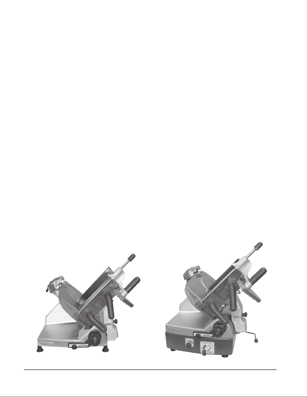
The model 2812 and 2912 slicers are equipped with a 1⁄2 HP (0.37 KW) motor and are available for
single-phase electrical service. The slicer features the exclusive Hobart Stay-Sharp contoured cast
solid stainless steel knife. The slicer is furnished with a cord and plug as standard equipment. Other
features and options include:
The Power Interrupt feature, standard, requires the slicer to be manually re-started after a power
interruption.
The Gauge Plate and Carriage Interlock feature, standard, prevents the Carriage Tray from being
removed unless the Carriage is in the H
Plate is C
previously been turned O
be started and the Gauge Plate cannot be opened until the Carriage Tray is returned to its normal
operating position.
LOSED. When the Carriage Tray is tilted horizontally, the slicer will turn OFF if it has not
FF. Once the Carriage Tray is tilted horizontally or removed, the slicer cannot
OME position (pulled all the way to the front) and the Gauge
The HomeStart feature, standard, requires the carriage to be in the H
can be started.
The 2912 slicer features automatic slicing with six adjustable speeds.
A tubular food chute, 4" (102 mm) leg set and slaw tray are other available accessories for 2812 and
2912. The low carriage fence is an accessory on 2812; it is standard on 2912. A high carriage fence
is an accessory used with front mounted meat grips. The standard meat grip is front-mounted. Heavy
front-mounted meat grip is an available accessory.
Model 2812 Slicer Model 2912 Slicer
OME position before the slicer
– 2 –
Page 3
INSTALLATION
UNPACKING
Immediately after unpacking the slicer, check for possible shipping damage. If the slicer is found to be
damaged, save the packaging material and contact the carrier within 15 days of delivery.
Prior to installing the slicer, test the electrical service to assure it agrees with the specifications on the
machine data plate. The data plate is located on the right side of the slicer base.
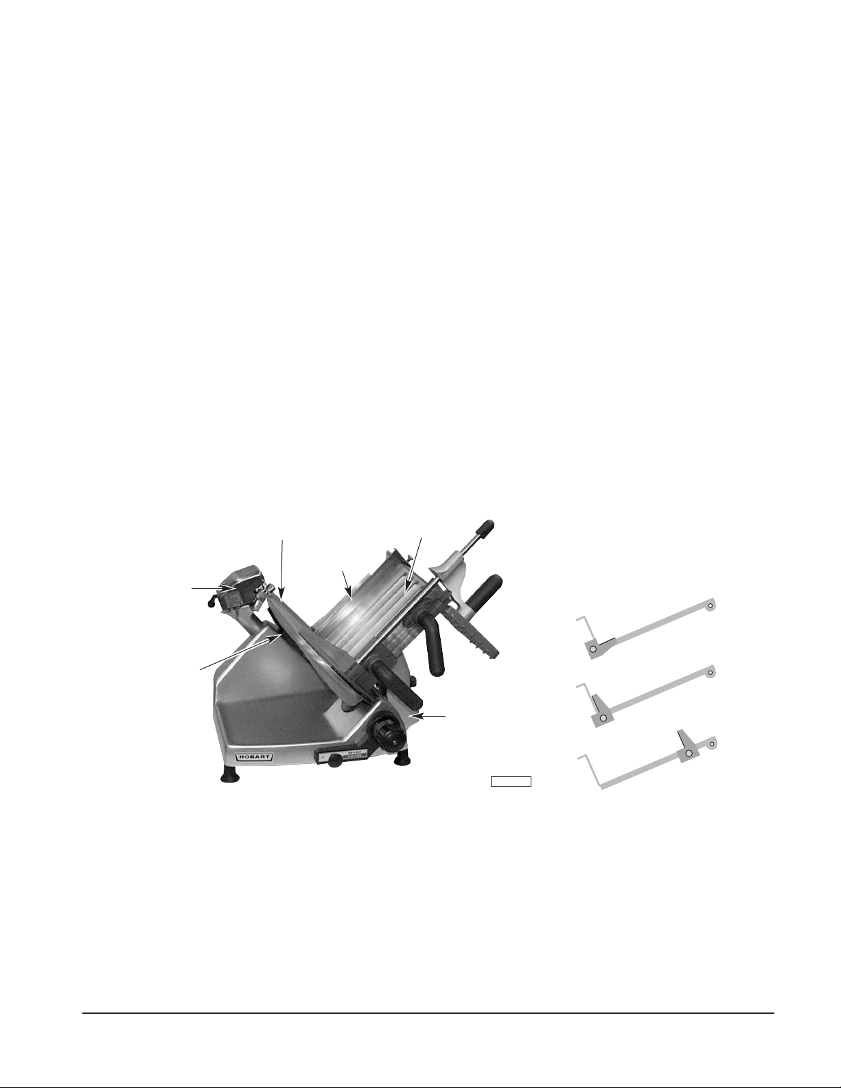
CARRIAGE TRAY
The Carriage Tray is secured to the slicer when the knob on the Carriage Tray / Support Arm is turned
clockwise until snug (Fig. 1). Refer to page 7 for assembly information.
SHARPENER
The Sharpener should already be mounted on top of the slicer and locked to its bracket (Fig. 1).
TOP KNIFE COVER
The Top Knife Cover should already be in place and secured with its Latch Knob (Fig. 1).
DEFLECTOR
The Deflector should already be mounted below the knife (Fig. 1).
FENCE (Low and High Fences are used with front-mounted meat grip only.)
Either Fence (Fig. 1) can be clamped on the Carriage Tray to limit product movement during slicing.
Model 2812
SHARPENER
DEFLECTOR
TOP KNIFE COVER
FENCE
CARRIAGE TRAY
CARRIAGE TRAY /
SUPPORT ARM
Fig. 1
PL-41408-1
1. Back out Thumb Screw.
Lay Fence on Carriage Tray.
2. Rotate to Vertical.
3. Slide Fence Up. Tighten Screw.
ELECTRICAL
WARNING: THIS MACHINE IS PROVIDED WITH A THREE-PRONG GROUNDING PLUG. THE
OUTLET TO WHICH THIS PLUG IS CONNECTED MUST BE PROPERLY GROUNDED. IF THE
RECEPTACLE IS NOT THE PROPER GROUNDING TYPE, CONTACT AN ELECTRICIAN.
CLEAN BEFORE USING
The 2812 or 2912 slicer must be thoroughly cleaned and sanitized after installation and before being
used. Refer to Cleaning, page 6.
– 3 –
Page 4
OPERATION
SAFETY
SAFETY DEVICES INCORPORATED IN THIS SLICER MUST BE IN THEIR CORRECT OPERATING
POSITIONS ANYTIME THE SLICER IS IN USE.
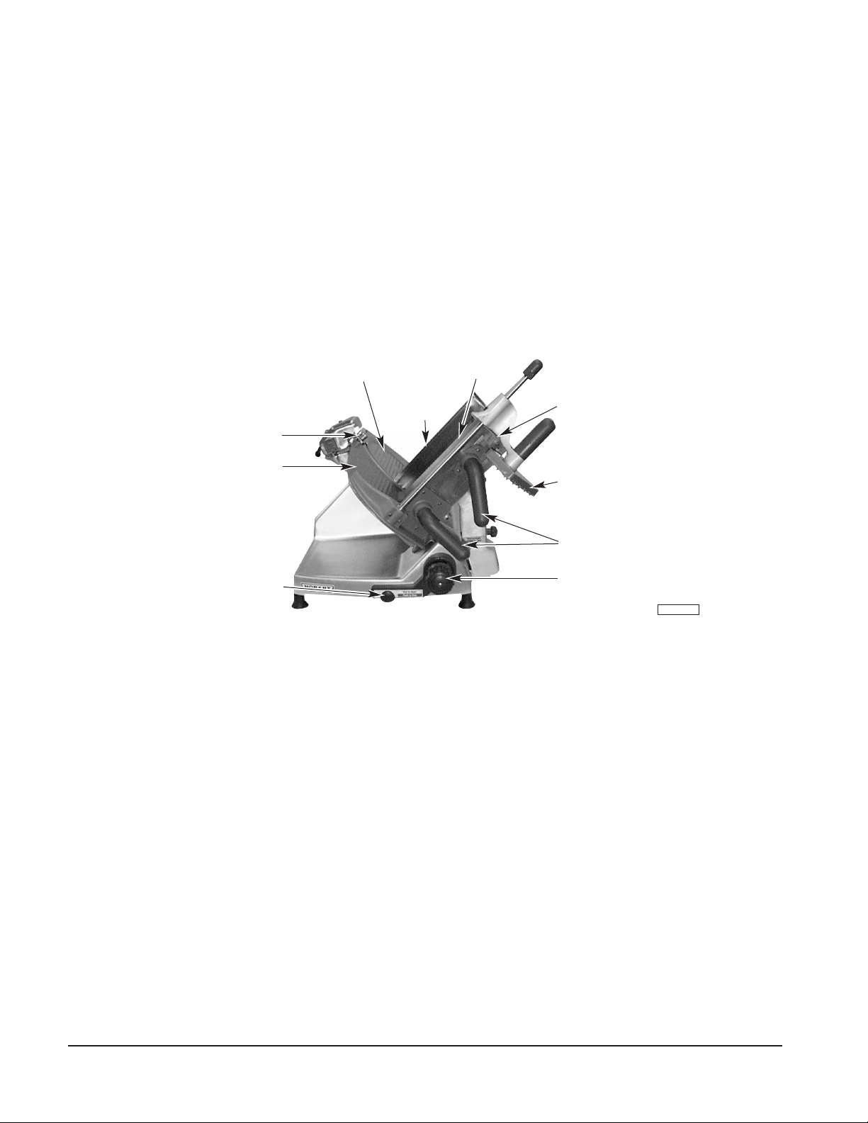
The TOP KNIFE COVER must be in position and secured with the LATCH KNOB (Fig. 2). The RING GUARD is
not removable. The D
EFLECTOR, mounted below the slicer knife, can be removed for cleaning.
The M
EAT GRIP (Fig. 2) must be used when slicing short ends to keep your hand(s) away from the knife.
When the slicer is not running, the I
The G
Always UNPLUG the P
AUGE PLATE will then cover the knife edge.
OWER CORD before cleaning or moving the Slicer.
Model 2812
LATCH KNOB
GAUGE PLATE
SWITCH KNOB
NDEX KNOB (Fig. 2) must be turned back below zero (fully clockwise).
TOP KNIFE COVER
CARRIAGE TRAY
FENCE
Fig. 2
RETAINING CLIP
MEAT GRIP
CARRIAGE TRAY HANDLES
INDEX KNOB
PL-41409-1
WARNING: ROTATING KNIFE. USE FEED GRIP. UNPLUG MACHINE POWER CORD BEFORE
CLEANING, SERVICING, OR REMOVING PARTS. REPLACE PARTS BEFORE USE.
SLICING — MODEL 2812
With the Gauge Plate fully closed, pull the Carriage all the way toward you until it reaches its stop. With
the Meat Grip out of the way, place the product to be sliced on the Carriage Tray. Set the Meat Grip
against the product.
If the Meat Grip is not needed, it may be stored out of the way by rotating it behind the top of the Carriage
Tray where it can rest on the Retaining Clip (Fig. 2).
Adjust the Gauge Plate to obtain the desired slice thickness by turning the Index Knob (Fig. 2). The
numbers on the Index Knob do not indicate actual measurements but may be used for reference to
duplicate slice thickness. Turn the slicer on by pulling the Switch Knob (Fig. 2) forward until it starts
and then releasing it. Slicer will not stay on unless the gauge plate is opened first. Unless the Gauge
Plate is opened before pulling the Switch Knob on, the slicer will not continue to run when the Switch
Knob is released.
Use either Carriage Tray Handle (Fig. 2) to push the Carriage back and forth to slice.
Turn the slicer off by pushing the Switch Knob or by closing the Gauge Plate.
– 4 –
Page 5

SLICING — MODEL 2912
With the Gauge Plate fully closed, pull the Carriage all the way toward you until it reaches its stop. With
the Meat Grip out of the way, place the product to be sliced on the Carriage Tray. Adjust the fence by
loosening the thumb screw and sliding the fence so that it is close to the product but not pushing against
it. Tighten the thumb screw. Set the Meat Grip against the product. Always make sure the Lever
(Fig. 3) is in the Manual position (down) before starting the slicer.
If the Meat Grip is not needed, it may be stored out of the way by sliding it to the top of its travel, rotating
it under the Carriage Tray, and allowing it to rest in the Retaining Clip (Fig. 3).
Adjust the Gauge Plate by turning the Index Knob (Fig. 3) to obtain the desired slice thickness. The
numbers on the Index Knob do not indicate actual measurements but may be used for reference to
duplicate slice thickness. Turn the slicer on by pulling the Switch Knob (Fig. 3) forward until it starts
and then releasing it. Unless the Gauge Plate is opened before pulling the Switch Knob on, the slicer
will not continue to run when the Switch Knob is released.
Use either Carriage Tray Handle (Fig. 3) to push the Carriage back and forth to slice manually.
Turn the slicer off by pushing the Switch Knob or by closing the Gauge Plate.
To operate the slicer in Automatic mode . . . Rotate the Speed Selector Knob (Fig. 3) to the desired
speed; make sure the Carriage is in H
OME position (all the way forward); make sure the Lever (Fig. 3)
is on the Manual position (pointing down); turn the slicer on; start the carriage drive unit by rotating the
Lever to the Automatic position (up and to the right).
Any of the six speed selections can be used to begin Automatic mode. The speed can be adjusted at
any time by rotating the Speed Selector Knob.
To stop the drive unit, rotate the Lever down and to the left — to the Manual position.
To use the optional Food Chute, place the Meat Grip on the Retaining Clip, fit the hangers on the Food
Chute around the meat grip slide rod (at front), and lower the Food Chute onto the Carriage Tray.
Model 2912
SHARPENER
SWITCH KNOB
SPEED SELECTOR KNOB
LATCH KNOB
TOP KNIFE
GAUGE PLATE
CARRIAGE TRAY
RETAINING CLIP
COVER
MEAT GRIP
CARRIAGE HANDLES
INDEX KNOB
LEVER IN MANUAL (DOWN) POSITION
PL-41257-1
Fig. 3
– 5 –
Page 6

CLEANING
This machine must be thoroughly cleaned and sanitized after each day’s operation or after being idle
for an extended period of time.
WARNING: THE SLICER KNIFE IS VERY SHARP.
EXERCISE EXTREME CAUTION WHEN WORKING
LATCH KNOB
TOP KNIFE COVER
CARRIAGE TRAY
NEAR THE KNIFE.
WARNING: UNPLUG MACHINE POWER CORD
AND TURN THE INDEX KNOB FULLY CLOCKWISE
BEFORE CLEANING THE SLICER.
Use a clean cloth soaked in mild detergent and warm
water to wipe all surfaces of the machine. Rinse
using a fresh cloth and clean water. Use only
products formulated to be safe on stainless steel or
Fig. 4
KNOB
CARRIAGE TRAY /
SUPPORT ARM
PL-41258-1
aluminum.
To clean the Carriage Tray, close the gauge plate and pull the Carriage all the way to the front. Unscrew
the Knob on the Carriage Tray / Support Arm (Fig. 4). Tilt the Carriage Tray / Support Arm to the right
until almost horizontal (Fig. 4). The Carriage Tray / Support Arm can be cleaned while in this horizontal
position, or it can be removed by grasping with both hands and lifting straight up. Once removed, the
Carriage Tray / Support Arm can be cleaned in a sink. NOTE: The last three digits of the slicer serial
number are etched on the Key (Fig. 8) so you can make sure the Carriage Tray stays with its own slicer.
Remove the Top Knife Cover by rotating the Latch Knob (Fig. 4) counterclockwise and lifting it free of
the guide pins. Remove the Deflector (Fig. 1) from its mount below the slicer knife by rotating
downward. Clean both Top Knife Cover and Deflector with warm soapy water in a sink. Rinse with
clean water.
LOCK LEVER
SHARPENER
KNIFE
GAUGE PLATE
PL-41402-1
Fig. 5 Fig. 6
RING GUARD
KNIFE
PAPER TOWEL
GAUGE PLATE
PL-41403-1
Remove the sharpener by pushing the Lock Lever to the left (Fig. 5). Tilt the right side up, clearing the
right guide pin, then lift the sharpener up, clearing the left guide pin. Wipe out any residue remaining
inside the sharpener housing and clean the sharpener in a sink. Rinse with fresh water.
Clean completely around the Ring Guard by working a moistened, folded paper towel between the Ring
Guard and Knife. Insert the towel at the base of the Ring Guard. Manually rotate the knife and the
towel will wipe the Ring Guard and the edge of the Gauge Plate as it follows the knife (Fig. 6).
Wash and rinse both sides of the knife by wiping outward from the center. Use a mild detergent or
sanitizer solution only. Never clean any part of the slicer with steel pads.
Do not exceed chemical manufacturer’s recommended concentrations for detergent or sanitizer. Do
– 6 –
Page 7

not exceed 200 parts per million concentration of available
chlorine. For example, mixing 1 tablespoon (15 ml) of
5.25% sodium hypochlorite bleach with 1 gallon (4.5 litres)
of water yields a solution containing 200 ppm of available
chlorine. Solution with concentrations greater than 200
ppm will accelerate corrosion of metals. Maximum
exposure to sanitation solution varies with temperature
and concentration. Rinse with clean water.
SHARPENER
KNIFE
GAUGE PLATE
Reassemble the sharpener to the mounting bracket by
sliding the left slot on the sharpener over the left guide
pin on the bracket while tilting slightly (Fig. 7). Then,
press down on the right side of the sharpener so the
locking hole fits over the right guide pin on the bracket.
Slide the Lock Lever to the right to lock the sharpener in
position. Make sure the sharpener is securely engaged
to the pins on the bracket.
Carefully reassemble the Top Knife Cover by putting it
in position (three guide pins). Lock by turning the Latch
Knob to the left while lowering the Top Knife Cover;
then, release the Latch Knob and turn it to the right until
snug.
Replace the Deflector below the slicer knife: Guide
bottom of socket onto mount and rotate upwards.
Make sure the digits etched on the Key (Fig. 8) match
the last three digits of the slicer serial number. To
reinstall the Carriage Tray / Support Arm: Hold it with
both hands and lower it so the Key at the bottom of the
Support Arm fits into the slot of the Carriage Pivot
(Fig. 8). The Carriage Tray should rest almost horizontal
(Fig. 4). Return the Carriage Tray to the Gauge Plate by
tilting to the left. Turn the Knob on the Carriage Tray /
Support Arm clockwise until snug.
The model 2812 slicer has a Cleaning Leg underneath
the machine. To engage the Cleaning Leg, raise the
front of the slicer by lifting the front of the slicer base.
The Cleaning Leg will swing straight down. Pull the
Cleaning Leg all the way to the front so the slicer is
completely supported before cleaning underneath
(Fig. 9).
LOCK LEVER
CARRIAGE TRAY /
SUPPORT ARM
CLEANING LEG
MODEL 2912 –
RAISED FOR CLEANING
PL-41402-1
Fig. 7
KEY
CARRIAGE PIVOT
PL-41248-1
Fig. 8
PL-40866-1
Fig. 9
LIFT LEVER –
RAISED PAST CENTER
To clean under the model 2912 slicer, raise the Lift
Lever past center to its stop (Fig. 10). After cleaning,
return the slicer to its normal position by slowly retracting
the Lift Lever.
DO NOT wash any slicer components in a dishwasher.
DO NOT immerse slicer base or motor in water.
Fig. 10
PL-41259-1
If using a chlorinated sanitizing solution, dilute per manufacturer’s guidelines. Rinse with fresh water.
NOTE: Failure to follow use, care, and maintenance instructions may void your Hobart warranty.
– 7 –
Page 8

MAINTENANCE
KNIFE SHARPENING
The Hobart cast stainless steel knife will provide long service in normal food retail or commercial
kitchen use. However, in high volume applications where it is a practice to sharpen the knife frequently
or even daily, the knife will be expended in a shorter time.
Sharpen only when necessary; prolonged or too frequent sharpening results in unnecessary
knife wear.
WARNING: UNPLUG MACHINE POWER CORD.
Turn the index knob fully clockwise to close the gauge plate. Remove the Top Knife Cover by rotating
the Latch Knob counterclockwise and lifting it off the slicer. Thoroughly wash the area around the knife,
the exposed knife surfaces, and the knife edge. Fat from meat or cheese should not be allowed to
transfer from the knife to the sharpener.
Plug in machine power cord. With the carriage tray
pulled fully forward, start the slicer with your right
hand by pulling the start switch forward and holding
it out. If the sharpener handle is the type that does
not hang downwards, pull it fully forward for 5 seconds
(Fig. 11). If the sharpener handle does hang
downwards, lift it with your left hand until horizontal
and pull forward for 5 seconds (Fig. 11). Slowly
release the sharpener handle. Release the switch
knob to turn the slicer off. If necessary, repeat
sharpening for another 5 seconds.
Unplug machine power cord. Wipe the slicer with a
clean damp cloth to remove any grinding particles.
Replace the Top Knife Cover.
TO SHARPEN:
PULL SHARPENER HANDLE
FULLY FORWARD
FOR 5 SECONDS
TOP KNIFE COVER
IS REMOVED
PL-41404-1
Fig. 11
LUBRICATION — Carriage Slide Rod
Lubricate the Carriage Slide Rod with Lubriplate
FMO-200-AW oil (supplied). Either squirt 8 – 10
WICK HOLE
drops every 2 – 3 months (depending on usage) in
the Wick Hole on the Carriage Transport (Fig.12).
Or, once monthly, apply 4 – 5 drops directly on the
Carriage Slide Rod on each side of the Carriage
Transport (Fig.12).
To apply oil, pull out the telescoping tube on the oil
bottle, aim the tube, and squeeze gently on the
sides of the bottle. After applying oil, move the
CARRIAGE SLIDE ROD
CARRIAGE TRANSPORT
PL-41146-1
Carriage Tray back and forth a few times so the oil
spreads over the entire length of the slide rod.
Fig. 12
OVERLOAD RESET BUTTON — MODEL 2912
Push the reset button underneath the slicer near the right-front foot if the carriage motor overloads.
SERVICE
Contact your local Hobart-authorized service office for any repairs or adjustments needed on this
equipment.
F33251 (801) [F34454.200] PRINTED IN THE U.S.A.
– 8 –
Page 9

TRANCHEURS 2812 ET 2912
O
D
E
D
’
E
M
P
L
O
I
M
CONVIENT AUX MODÈLES SUIVANTS :
TRANCHEUR 2812
MODÈLES
2812 ML-104959
2912 ML-104964
CONVIENT AUSSI AUX ANCIENS MODÈLES :
2812 ML-104618
ML-104826
2912 ML-104761
ML-104821
190 Railside Road
North York (Ontario)
M3A 1B1
F33251 (801) [F34454.200] IMPRIMÉ AUX É.-U.
Page 10

Installation, fonctionnement et entretien
TRANCHEURS 2812 ET 2912
DOCUMENT À CONSERVER
GÉNÉRALITÉS
Les trancheurs 2812 et 2912 équipés d’un moteur de 0,37 kW (1⁄2 CV) fonctionnent en courant
monophasé. L’équipement standard comprend un couteau profilé en acier inoxydable massif
Stay-Sharp exclusif à Hobart, un cordon et une fiche d’alimentation.
Autres caractéristiques standard et en option :
Interrupteur de sécurité (standard) : suite à une coupure de courant, l’utilisateur doit remettre
l’appareil en marche manuellement.
Verrouillage de la plaque de coupe et du chariot (standard) : le chariot s’enlève uniquement s’il est
à la position REPOS (ramené complètement à l’avant) et si la plaque de coupe est FERMÉE. Dès que
le chariot est positionné à l’horizontale, le trancheur s’éteint automatiquement si l’utilisateur ne l’a pas
déjà fait. Il est impossible de faire fonctionner le trancheur et d’ouvrir la plaque de coupe si le chariot
ne se trouve pas à sa position de fonctionnement appropriée.
Position REPOS (standard) : l’utilisateur doit s’assurer que le chariot est à la position REPOS avant
de mettre l’appareil en marche.
Le trancheur 2912 comporte six vitesses de tranchage automatique.
Une trémie tubulaire et un jeu de pattes de 102 mm (4 po) sont offerts en option. Une cloison basse
standard pour le modèle 2912, mais offerte en option pour le 2812. Une cloison élevée pour utilisation
avec pousse-talon fixé à l’avant est aussi offerte en option. Le pousse-talon standard se trouve à
l’avant du trancheur. Un pousse-talon à service intense aussi fixé à l’avant est offert en option.
Trancheur 2812 Trancheur 2912
– 2 –
Page 11

INSTALLATION
DÉBALLAGE
Immédiatement après avoir déballé le trancheur, vérifier s’il n’a pas été endommagé lors du transport.
En cas de dommages, conserver le matériel d’emballage et communiquer avec le transporteur dans
les 15 jours suivant la date de réception.
Avant d’installer le trancheur, s’assurer que l’alimentation électrique de l’immeuble correspond aux
spécifications de la plaque signalétique sur le côté droit de l’appareil.
CHARIOT
Pour fixer le chariot au trancheur, tourner le bouton qui se trouve sur le bras support dans le sens des
aiguilles d’une montre jusqu’à ce qu’il soit bien serré (Fig. 1). Se reporter en page 7 pour de plus
amples détails sur l’assemblage.
AFFÛTEUSE
S’assurer que l’affûteuse est fixée au support sur le dessus du trancheur (Fig. 1).
PLAQUE PROTECTRICE DU COUTEAU
S’assurer que la plaque protectrice du couteau est en place et retenue au moyen du bouton de
verrouillage (Fig. 1).
DÉFLECTEUR
S’assurer que le déflecteur est en place en dessous du couteau (Fig. 1).
CLOISON (cloisons basses et élevées pour utilisation avec pousse-talon fixé à l’avant uniquement).
La cloison basse ou élevée (Fig. 1) se fixe au chariot en vue de limiter le mouvement du produit pendant
le tranchage.
PLAQUE PROTECTRICE
DU COUTEAU
CLOISON
AFFÛTEUSE
DÉFLECTEUR
Fig. 1
CHARIOT
BRAS SUPPORT
DE CHARIOT
PL-41408-1
1. Dévisser la vis à serrage
manuel. Positionner la
cloison sur le chariot.
2. Amener à la verticale.
3. Ramener la cloison vers le haut.
Serrer la vis.
ALIMENTATION ÉLECTRIQUE
AVERTISSEMENT : CET APPAREIL EST POURVU D’UNE FICHE À TROIS BROCHES DONT UNE
MISE À LA TERRE. LA PRISE DANS LAQUELLE ELLE EST BRANCHÉE DOIT ÊTRE
CORRECTEMENT MISE À LA TERRE. SI ELLE NE L’EST PAS, COMMUNIQUER AVEC UN
ÉLECTRICIEN.
NETTOYAGE AVANT UNE PREMIÈRE UTILISATION
Nettoyer et désinfecter l’appareil à fond après l’avoir installé et avant de l’utiliser. Se reporter à la
section NETTOYAGE en page 6.
– 3 –
Page 12

FONCTIONNEMENT
DISPOSITIFS DE SÉCURITÉ
S’ASSURER QUE LES DISPOSITIFS DE SÉCURITÉ DU TRANCHEUR SONT À LA POSITION
APPROPRIÉE AVANT CHAQUE USAGE.
La PLAQUE PROTECTRICE DU COUTEAU doit être maintenue en position par le BOUTON DE
VERROUILLAGE (Fig. 2). La BAGUE DE PROTECTION est fixée en permanence. Le DÉFLECTEUR
fixé derrière la lame s’enlève aux fins de nettoyage.
Utiliser le POUSSE-TALON (Fig. 2) pour trancher les petits bouts de produits de façon à garder les
mains éloignées du couteau.
Lorsque le trancheur ne sert pas, mettre le BOUTON DE RÉGLAGE (Fig. 2) à zéro (un tour complet
dans le sens des aiguilles d’une montre). La PLAQUE DE COUPE empêchera alors l’exposition du
tranchant de couteau.
Toujours DÉBRANCHER l’appareil avant de le nettoyer ou de le déplacer.
Modèle 2812
PLAQUE DE COUPE
PLAQUE PROTECTRICE
DU COUTEAU
CLOISON
BOUTON DE
VERROUILLAGE
INTERRUPTEUR
Fig. 2
CHARIOT
PINCE DE RETENUE
POUSSE-TALON
POIGNÉE DU CHARIOT
BOUTON DE
RÉGLAGE
PL-41409-1
AVERTISSEMENT : COUTEAU ROTATIF. SE SERVIR DU POUSSE-TALON. DÉBRANCHER
L’APPAREIL AVANT TOUT NETTOYAGE, ENTRETIEN OU L’ENLÈVEMENT DE PIÈCES. REMETTRE
LE TOUT EN PLACE AVANT D’UTILISER L’APPAREIL.
TRANCHAGE - MODÈLE 2812
Fermer complètement la plaque de coupe et tirer le chariot vers soi jusqu’au bout de sa course.
Éloigner le pousse-talon et mettre le produit sur le chariot. Appuyer le pousse-talon contre le produit.
Pour ranger le pousse-talon s’il ne sert pas, le faire glisser jusqu’au point le plus élevé de sa course
et le pousser sous le chariot jusqu’à ce qu’il repose sur la pince de retenue (Fig. 2).
Pour obtenir l’épaisseur désirée des tranches, régler la plaque de coupe en tournant le bouton de
réglage (Fig. 2). Les chiffres de ce bouton servent à déterminer l’épaisseur des tranches et ne
représentent pas des unités de mesure réelles. Ils peuvent toutefois servir de référence pour produire
à nouveau des tranches de la même épaisseur. Allumer le trancheur en tirant sur l’interrupteur (Fig.
2); le relâcher dès qu’il fonctionne. Avant de tirer sur l’interrupteur, ouvrir la plaque de coupe sinon le
trancheur s’éteint dès qu’on relâche l’interrupteur.
Pour trancher, imprégner un mouvement de va-et-vient au chariot en le tenant par l’une des deux
poignées (Fig. 2).
Éteindre le trancheur en appuyant sur l’interrupteur ou en fermant la plaque de coupe.
– 4 –
Page 13

TRANCHAGE - MODÈLE 2912
Fermer complètement la plaque de coupe et tirer le chariot vers soi jusqu’au bout de sa course.
Éloigner le pousse-talon et mettre le produit sur le chariot. Régler la cloison en desserrant la vis à
serrage manuel et la glisser de façon qu’elle soit près du produit sans toutefois appliquer de pression
sur celui-ci. Serrer la vis. Appuyer le pousse-talon contre le produit. Toujours s’assurer que le levier
(Fig. 3) est à la position MANUEL (en bas) avant de mettre le trancheur en marche.
Pour ranger le pousse-talon s’il ne sert pas, le faire glisser jusqu’au point le plus élevé de sa course
et le pousser sous le chariot jusqu’à ce qu’il repose sur la pince de retenue (Fig. 3).
Pour obtenir l’épaisseur désirée des tranches, régler la plaque de coupe en tournant le bouton de
réglage (Fig. 3). Les chiffres de ce bouton servent à déterminer l’épaisseur des tranches et ne
représentent pas des unités de mesure réelles. Ils peuvent toutefois servir de référence pour produire
à nouveau des tranches de la même épaisseur. Allumer le trancheur en tirant sur l’interrupteur (Fig. 3);
le relâcher dès qu’il fonctionne. Avant de tirer sur l’interrupteur, ouvrir la plaque de coupe sinon le
trancheur s’éteint dès qu’on relâche l’interrupteur.
Pour trancher, imprégner un mouvement de va-et-vient au chariot en le tenant par l’une des deux
poignées (Fig. 3).
Éteindre le trancheur en appuyant sur l’interrupteur ou en fermant la plaque de coupe.
Pour l’utilisation du trancheur en mode automatique, tourner le sélecteur de vitesse (Fig. 3) jusqu’à la
vitesse désirée. S’assurer que le chariot est à la position REPOS (jusqu’à la fin de sa course) et le
levier (Fig. 3) à la position MANUEL (vers le bas). Mettre le trancheur en marche et le levier à la position
AUTOMATIQUE (en haut à droite) pour embrayer le mécanisme d’entraînement.
Régler le sélecteur à l’une des six vitesses pour amorcer le tranchage automatique. On peut régler
la vitesse en tout temps au moyen du sélecteur.
Pour dégager le mécanisme d’entraînement, tourner le levier vers le bas à gauche, c’est-à-dire jusqu’à
la position MANUEL.
Pour utiliser la goulotte de déversement offerte en option, placer le pousse-talon sur la pince de
retenue, ajuster les crochets de suspension sur la goulotte de déversement autour de la barre de
glissement du pousse-talon (à l’avant), et abaisser la goulotte de déversement dans le chariot.
Modèle 2912
AFFÛTEUSE
PLAQUE DE COUPE
INTERRUPTEUR
BOUTON DE
VERROUILLAGE
PLAQUE
PROTECTRICE
DU COUTEAU
CHARIOT
PINCE DE RETENUE
POUSSE-TALON
POIGNÉE DU CHARIOT
SÉLECTEUR DE VITESSE
LEVIER À LA POSITION MANUEL (BAS)
Fig. 3
– 5 –
BOUTON DE RÉGLAGE
PL-41257-1
Page 14

NETTOYAGE
PL-41403-1
PLAQUE DE COUPE
COUTEAU
BAGUE DE
PROTECTION
SERVIETTE DE
PAPIER
Nettoyer et désinfecter l’appareil à fond après
chaque journée d’utilisation et toute période
d’inactivité prolongée.
AVERTISSEMENT : LE COUTEAU EST TRÈS
BOUTON DE
VERROUILLAGE
PLAQUE PROTECTRICE
DU COUTEAU
CHARIOT
TRANCHANT. EXERCER UNE EXTRÊME
PRUDENCE EN MANOEUVRANT PRÈS DE
CELUI-CI.
AVERTISSEMENT : DÉBRANCHER L’APPAREIL
ET TOURNER LE BOUTON DE RÉGLAGE D’UN
TOUR COMPLET DANS LE SENS DES
AIGUILLES D’UNE MONTRE AVANT DE
PROCÉDER AU NETTOYAGE.
À l’aide d’une solution d’eau chaude savonneuse
Fig. 4
BOUTON
BRAS SUPPORT
DE CHARIOT
PL-41258-1
et d’un chiffon propre, essuyer toutes les surfaces de l’appareil. Rincer à l’eau fraîche à l’aide d’un
chiffon propre. Utiliser uniquement des produits recommandés pour l’acier inoxydable et l’aluminium.
Pour le nettoyage du chariot, fermer la plaque de coupe et tirer le chariot vers soi jusqu’au bout de sa
course. Dévisser le bouton du bras support de chariot (Fig. 4). Incliner le bras vers la droite jusqu’à
ce qu’il soit presqu’à l’horizontale (Fig. 4). Le nettoyer dans cette position ou le saisir à deux mains
et l’enlever dans cette position en le soulevant vers le haut. Le nettoyer dans un évier. NOTA : Les
trois derniers chiffres du numéro de série du trancheur sont gravés sur la clavette (Fig. 8) de sorte que
le chariot ne peut être utilisé que sur le trancheur correspondant.
Pour enlever la plaque protectrice du couteau, tourner le bouton de verrouillage (Fig. 4) dans le sens
contraire des aiguilles d’une montre et la dégager des goupilles-guides. Enlever le déflecteur (Fig. 1)
fixé en dessous du couteau en le tournant vers le bas. Laver le déflecteur et la plaque protectrice du
couteau à l’eau chaude savonneuse dans un évier. Rincer à l’eau propre.
LEVIER DE
VERROUILLAGE
AFFÛTEUSE
Fig. 5
COUTEAU
PLAQUE DE
COUPE
PL-41402-1
Fig. 6
Enlever l’affûteuse en poussant le levier de verrouillage vers la gauche (Fig. 5). Incliner le côté droit
vers le haut de façon à dégager la goupille-guide droite, puis soulever l’affûteuse de façon à dégager
la goupille-guide gauche. Enlever toute trace de résidus à l’intérieur du boîtier de l’affûteuse et
nettoyer celle-ci dans un évier. Rincer à l’eau fraîche.
Laver tout le long de la bague de protection en insérant une serviette de papier pliée humide entre la
bague et le couteau à la base de la bague (Fig. 6). Tourner le couteau manuellement; la serviette
essuiera ainsi la bague qui suit le couteau.
Laver et rincer les deux côtés du couteau et l’essuyer du centre vers l’extérieur. Ne jamais utiliser un
tampon en acier pour le nettoyage du couteau ou de tout autre composant, mais plutôt un détergent
ou un désinfectant doux.
– 6 –
Page 15

PL-41259-1
BÉQUILLE LEVÉE
AU-DELÀ DU CENTRE
MODÈLE 2912 –
SOULEVÉ AUX
FINS DE NETTOYAGE
PL-41248-1
PIVOT DU
CHARIOT
CLAVETTE
BRAS SUPPORT
DE CHARIOT
PL-40866-1
PATTE DE
NETTOYAGE
Ne pas excéder les concentrations de détergent et de
désinfectant recommandées par le fabricant, ou une
concentration de 200 parties par million de chlore. Par
exemple, 15 ml (1 cuillère à table) d’hypochlorite de sodium
(agent de blanchiment) à 5,25 % mélangée à 4,5 litres
(1 gallon) d’eau donne une solution renfermant 200 ppm de
chlore. Une concentration supérieure à 200 ppm de chlore
accélère le processus de corrosion des métaux. L’exposition
maximale à une solution désinfectante varie en fonction de la
température et de la concentration. Rincer à l’eau propre.
Rassembler l’affûteuse au support de fixation en positionnant
l’encoche de gauche sur la goupille-guide gauche du support en
l’inclinant légèrement (Fig. 7). Appuyer ensuite sur le côté droit
de l’affûteuse de façon que la goupille-guide droite du support
s’insère dans le trou de verrouillage. Pousser le levier de
verrouillage vers la droite pour verrouiller l’affûteuse en place.
S’assurer que celle-ci est bien assujettie aux goupilles du
support.
Remettre soigneusement la plaque protectrice du couteau en
place (trois goupilles-guides). Tourner le bouton de verrouillage
vers la gauche en abaissant la plaque pour la verrouiller.
Relâcher ensuite le bouton et le tourner vers la droite jusqu’à ce
qu’il soit bien serré.
LEVIER DE
VERROUILLAGE
AFFÛTEUSE
Fig. 7
COUTEAU
PLAQUE DE
COUPE
PL-41402-1
Remettre le déflecteur en place en dessous du couteau :
Guider le bas du manchon sur l’assemblage et tourner
vers le haut.
S’assurer que les chiffres gravés sur la clavette (Fig. 8)
correspondent aux trois derniers chiffres du numéro de série
du trancheur. Pour remettre le bras support de chariot en
place, le tenir à deux mains et l’abaisser jusqu’à ce que la
clavette à la partie inférieure du bras s’insère dans la fente du
pivot du chariot (Fig. 8). Le chariot doit se trouver presqu’à
l’horizontale (Fig. 4). L’incliner vers la gauche pour le ramener
jusqu’à la plaque de coupe. Tourner le bouton du bras dans le
sens des aiguilles d’une montre jusqu’à ce qu’il soit bien serré.
Le trancheur 2812 est pourvu d’une patte facilitant le nettoyage
en dessous de l’appareil. Pour bloquer la patte en place,
soulever la partie avant du trancheur et ramener la patte
complètement vers le bas. S’assurer que l’appareil est bien
stable avant de nettoyer en dessous (Fig. 9).
Pour nettoyer le dessous du 2912, lever la béquille au-delà du
centre jusqu’à la fin de sa course (Fig. 10). Pour remettre le
trancheur en place après le nettoyage, redescendre doucement
la béquille à sa position originale.
Fig. 8
Fig. 9
NE laver AUCUNE pièce du trancheur dans un lave-vaisselle.
NE PAS immerger la base ou le moteur dans l’eau.
Si une solution désinfectante chlorée est utilisée pour le nettoyage,
diluer selon les directives du fabricant. Rincer à l’eau fraîche.
NOTA : À défaut de suivre les directives d’utilisation, de nettoyage
et d’entretien, la garantie Hobart sera annulée.
Fig. 10
– 7 –
Page 16

PL-41404-1
PLAQUE PROTECTRICE
DU COUTEAU ENLEVÉE
AFFÛTAGE :
TIRER LA POIGNÉE DE
L'AFFÛTEUSE VERS SOI
PENDANT 5 SECONDES
ENTRETIEN
PL-41146-1
ORIFICE DE LUBRIFICATION
PONT DU CHARIOT
BARRE DE GLISSEMENT
DU CHARIOT
AFFÛTAGE DE LA LAME
Lorsqu’on en fait une utilisation normale dans les magasins d’alimentation et les cuisines commerciales,
le couteau en acier inoxydable massif Hobart procure de nombreuses années de service. Toutefois,
une utilisation intense et des affûtages fréquents, voire journaliers, useront la lame plus rapidement.
Affûter la lame au besoin seulement. Un affûtage répété ou trop fréquent risque d’user la lame
prématurément.
AVERTISSEMENT : DÉBRANCHER L’APPAREIL.
Tourner le bouton de réglage d’un tour complet dans le sens des aiguilles d’une montre pour fermer la plaque
de coupe. Tourner le bouton de verrouillage dans le sens contraire des aiguilles d’une montre et soulever la
plaque protectrice du couteau pour l’enlever. Laver à fond la
partie visible du couteau, la région qui l’entoure et son
tranchant. S’assurer que la graisse provenant de la viande ou
du fromage n’entre pas en contact avec la pierre à affûter.
Brancher le trancheur. Tirer le chariot vers soi jusqu’au
bout de sa course et, de la main droite, tirer l’interrupteur
MARCHE vers soi; le tenir ainsi. De la main gauche,
amener la poignée de l’affûteuse à l’horizontale. La tirer
le plus loin possible vers soi pendant 5 secondes
(Fig. 11). La relâcher lentement. Relâcher l’interrupteur
pour éteindre l’appareil. Au besoin, procéder de nouveau
à l’affûtage pendant 5 secondes.
Fig. 11
Débrancher le trancheur. L’essuyer à l’aide d’un chiffon propre et humide pour enlever toutes les
particules d’affûtage. Remettre la plaque protectrice du couteau en place.
LUBRIFICATION - barre de glissement du chariot
Lubrifier la barre de glissement du chariot au moyen
d’huile Lubriplate FMO-200-AW ((fournie). Injecter de 8
à 10 gouttes tous les 2 ou 3 mois (selon l’usage qu’on fait
de l’appareil) dans l’orifice de lubrification sur le pont du
chariot (Fig. 12) ou 4 ou 5 gouttes tous les mois
directement sur la barre de glissement du chariot de
chaque côté du pont (Fig. 12).
Pour ce faire, ouvrir le tube télescopique de la bouteille
d’huile et presser doucement celle-ci. Une fois l’huile
appliquée, imprégner un mouvement de va-et-vient au
chariot plusieurs fois de façon qu’il y ait de l’huile sur
toute la surface de la barre de glissement.
BOUTON DE RÉENCLENCHEMENT - MODÈLE 2912
Appuyer sur le bouton de réenclenchement en dessous du trancheur, près du pied avant droit, en cas de
surcharge du moteur du chariot.
SERVICE DE L’ENTRETIEN
Fig. 12
Communiquer avec le service de l’entretien Hobart le plus près pour toute réparation ou tout réglage de
cet appareil.
F33251 (801) [F34454.200] IMPRIMÉ AUX É.-U.
– 8 –
 Loading...