

Page 1
CATALOG OF
REPLACEMENT PARTS
HQC90 CHILLER
HQC90 ML-124044
ML-124068
A product of HOBART CORPORATION 701 S. RIDGE AVENUE TROY, OHIO 45374-0001
FORM 43008 (June 2001)
Page 2

HQC90 CHILLER REPLACEMENT PARTS
Page Description
3 Control Box Assembly
5 Main Cabinet Assembly
6 Door Assembly
7 Pilasters/Food Probes Assembly
9 Internal Section Mechanical Parts Assembly
10 Upper Section Trim Unit (ML-124044)
11 Upper Section Trim Unit (ML-124068)
13 Printer Panel Unit
14 Control Panel Unit
15 Electrical Unit (ML-124068)
17 Electrical Unit (ML-124044)
19 Condensing Unit
Table of Contents
F-43008 (June 2001)
- 2 -
© HOBART CORPORATION
Page 3
HQC90 CHILLER REPLACEMENT PARTS
1
2
14
13
12
123
456
78
9
0
#
15
11
3
4
5 6-7 8 9 10
TO HIGH
VOLTAGE BOARD
TO TERMINAL BLOCKS
FOR DOOR SWITCHES
TO TEMPERATURE
PROBES
PL-53638
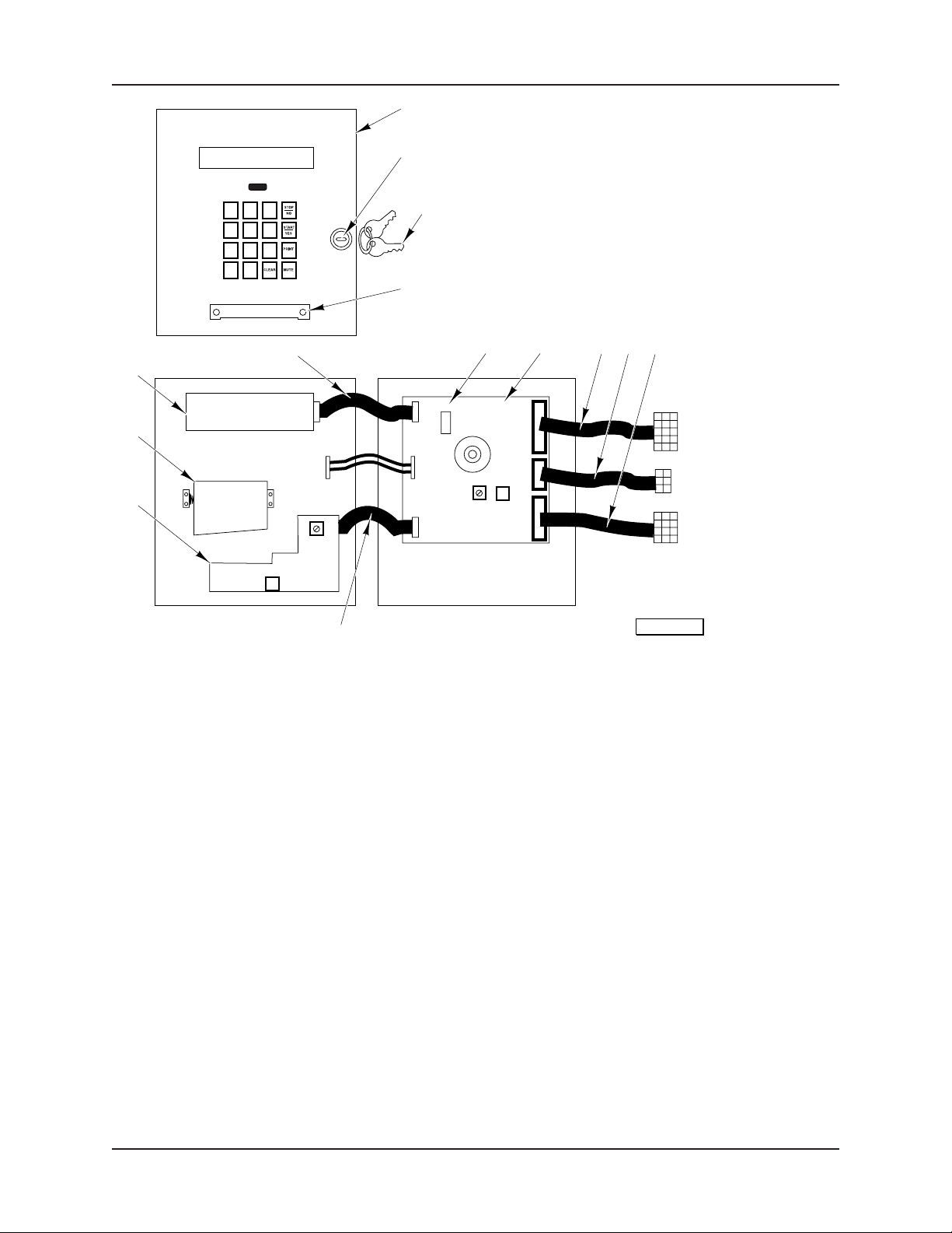
CONTROL BOX ASSEMBLY
(ML-124044)
ILLUS. PART NO. NAME OF PART AM T.
PL-53638
1 00-282053 Keypad – Membrane .................................................................................................................. 1
2 00-630184-00015 Door Lock ................................................................................................................................... 1
3 00-630154-00059 Keys – Door (CH 751) ................................................................................................................ 1
4 00-282127 Bar – Paper Tear ........................................................................................................................ 1
5 01-010453 Chip – Eprom (Version 2L) ......................................................................................................... 1
6 01-039271 Controller Board Assy. (Version 2L) ......................................................................................... 1
7 00-282049 Controller Board Assy. (Version 2D) ......................................................................................... 1
8 00-282066 Cable – Sensor Input .................................................................................................................. 1
9 00-630184-00016 Cable – Door Switches ..............................................................................................................1
10 00-282057 Cable – Food Probe Coil & Air .................................................................................................... 1
11 00-282069 Cable – Printer Interface ............................................................................................................ 1
12 00-282050 Printer Assy. (Use With Interface Board) ..................................................................................1
13 00-282051 Paper – Printer ............................................................................................................................ 1
14 00-282052 Display ........................................................................................................................................ 1
15 00-282070 Cable – Display ...........................................................................................................................1
00-630143-00056 Control Box Assy. (Incls. Items 1 thru 14) .................................................................................1
- 3 -
F-43008 (June 2001)
Page 4
HQC90 CHILLER REPLACEMENT PARTS
33
13
12
OR
17
16
15
14
11
10
PL-53639
31
7-8-9
6
4-5
2
1
30
32
29
3
27
28
18
19
26
20
21
20
25
22-23-24
25
F-43008 (June 2001)
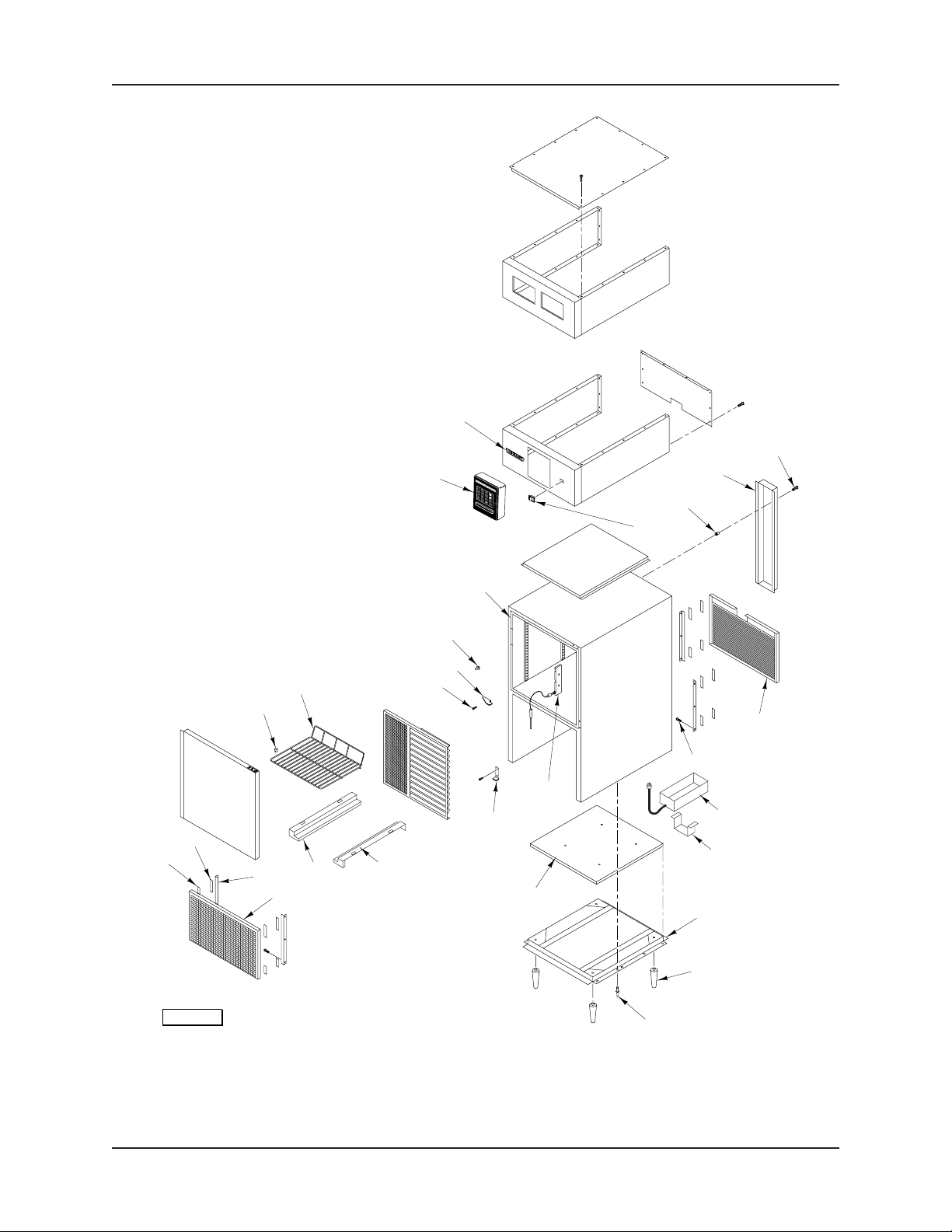
MAIN CABINET ASSEMBLY
- 4 -
Page 5

HQC90 CHILLER REPLACEMENT PARTS
MAIN CABINET ASSEMBLY
ILLUS. PART NO. NAME OF PART AM T.
PL-53639
1 00-630152-00084 Shelf Clips ................................................................................................................................. 20
2 00-630182-00082 Shelf 3/4 x 26 x 26 .......................................................................................................................5
3 01-012536 Bolt – Door Hinge ....................................................................................................................... 4
4 01-030423 Bracket – Right Hinge Upper ...................................................................................................... 1
5 01-030424 Bracket – Left Hinge Upper ....................................................................................................... 1
6 00-630181-00029 Light – Door Switch ................................................................................................................... 1
7 00-630181-00008 Cable – Door Frame Heater (23 OHM x 120") ........................................................................... 1
8 00-630183-00054 Thermostat – Door Frame Heater (Type B) ............................................................................... 1
9 00-630173-00070 Molding – Snap On (295/8 Lg.) (SST) ......................................................................................... 4
10 01-033626 Velcro Strip (5/8 x 2) (Hooks) ...................................................................................................... 8
11 01-033627 Velcro Strip (5/8 x 2) (Eyes) ........................................................................................................8
12 00-206177 Clip – Nameplate (Use with Item 13) ..........................................................................................2
13 00-280244 Hobart Logo ................................................................................................................................ 1
14 00-630183 Main Switch ................................................................................................................................ 1
15 01-008043 Nut – Trick 8-32 ..........................................................................................................................6
16 00-889012-00004 Line Cover ................................................................................................................................. 10
17 01-012525 Screw – Thread Cutting 8-32 x 1/2 (SST) .................................................................................. 6
18 00-889012 Cover – Compressor Back ........................................................................................................ 1
19 00-630161-00058 Screw 8-18 x 1/2 Sq. Hd. ...........................................................................................................12
20 01-030366 Pan – Condensate (With 3 Ft. Cord) (115 V.) ............................................................................ 1
21 00-889025-00001 Support – Condensate Pan ........................................................................................................1
22 01-030254 Caster W/O Brakes (Not Shown) .............................................................................................. 2
23 01-030255 Caster W/Brakes (Not Shown) .................................................................................................. 2
24 00-630153-00079 Legs – 6" (SST) .......................................................................................................................... 2
25 00-630161-00041 Rivets – Pop (3/16" SST) .............................................................................................................. 1
26 00-889008 Food Probes Connection Assy. ................................................................................................. 1
27 00-630180-00066 Bracket – Right Hinge (Lower) .................................................................................................. 1
28 00-630180-00067 Bracket – Left Hinge (Lower) .................................................................................................... 1
29 00-889011-00004 Track – Right .............................................................................................................................. 1
30 00-889011-00005 Track – Left ................................................................................................................................1
31 00-889012-00003 Angle – Bracket ..........................................................................................................................4
32 00-889021-00001 Grill – Front ................................................................................................................................. 1
33 00-630143-00056 Control Box Assy. (ML-124044) ................................................................................................ 1
- 5 -
F-43008 (June 2001)
Page 6
HQC90 CHILLER REPLACEMENT PARTS
1
2-3
6
7
4
5
8
9
PL-55036
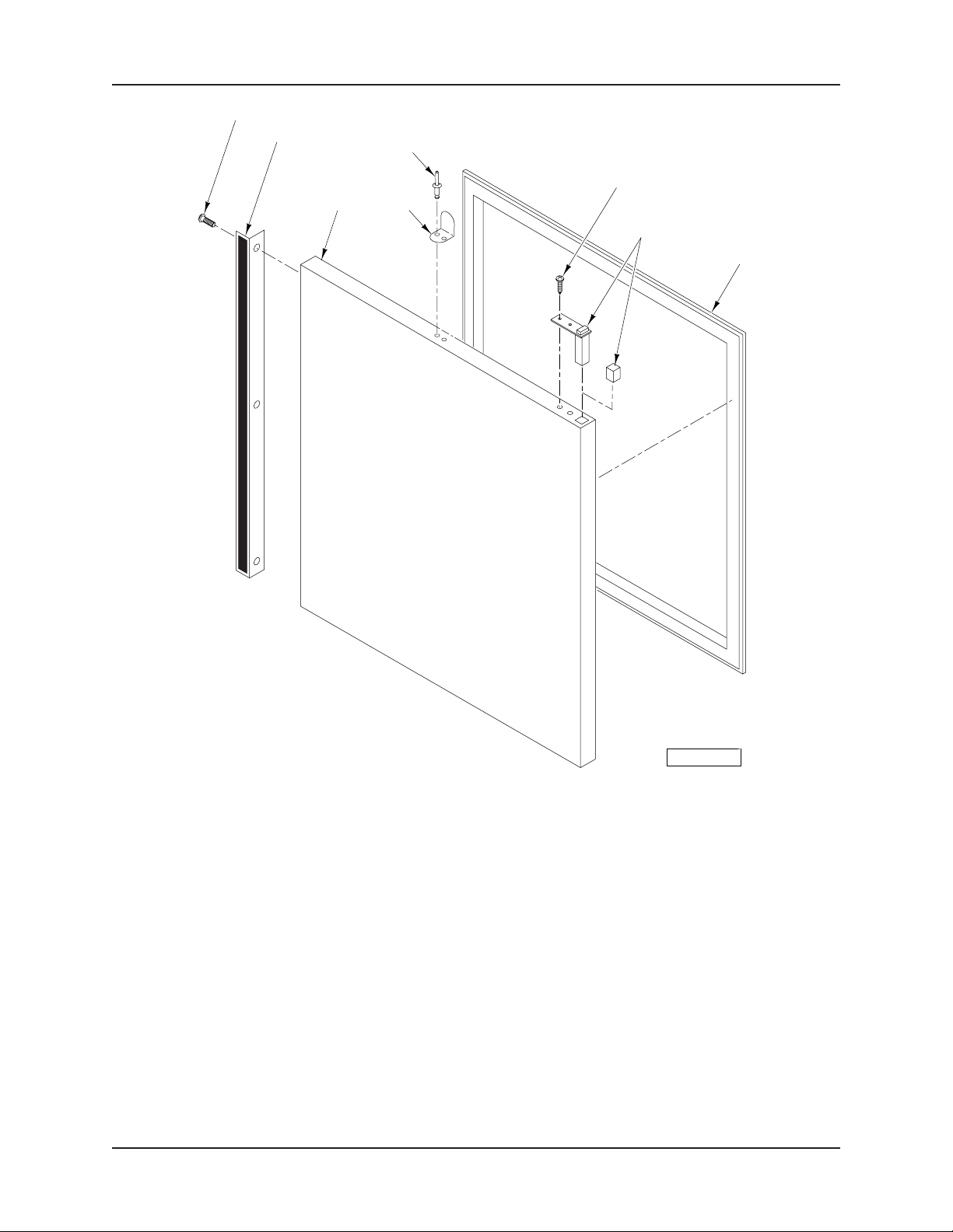
DOOR ASSEMBLY
ILLUS. PART NO. NAME OF PART AM T.
PL-55036
1 01-012525 Screw – Thread Cutting 8-32 x 1/2 (SST) .................................................................................. 3
2 00-630152-00085 Handle – Aluminum Extrusion 301/2" ........................................................................................... 1
3 01-023054 Black Laminated Steel 301/2" ....................................................................................................... 1
4 00-889004 Door Panel Assy. ........................................................................................................................1
5 00-630174-00068 Door Switch Activator................................................................................................................ 1
6 00-630161-00040 Rivet Pop 1/4" (SST) .................................................................................................................... 2
7 00-630162-00029 Screw 10-32 x 1 ........................................................................................................................2
8 00-630180-00065 Hinging Spring System ............................................................................................................... 1
9 00-630153-00043 Door Gasket ............................................................................................................................... 1
F-43008 (June 2001)
- 6 -
Page 7

HQC90 CHILLER REPLACEMENT PARTS
6
5
4
3
2
1
9
8
11
13
12
7
10
PL-53640
PILASTERS/FOOD PROBES ASSEMBLY
ILLUS. PART NO. NAME OF PART AM T.
PL-53640
1 00-889008-00002 Probe Support Cover (ML-124044) ........................................................................................... 1
2 00-889008-00004 Probe Support Cover (ML-124068) ........................................................................................... 1
3 00-889008-00001 Probe Support Base (ML-124044) ............................................................................................. 1
4 00-889008-00005 Probe Support Base (ML-124068) ............................................................................................. 1
5 00-889013-00001 Pilasters 26" Lg. ......................................................................................................................... 4
6 01-012562 Self-Tapping Screw 4 x 1/2 Slotted Pan Hd. ...............................................................................6
7 00-434330 Food Probe (39") (ML-124068) .................................................................................................. 3
8 01-008043 Nut – Trick 8-32 ......................................................................................................................... 10
9 01-012585 Mach. Screw 8-32 x 1/2 Phil. Rd. Hd. (SST) ..............................................................................10
10 00-889008-00003 Probe Holder ............................................................................................................................... 3
11 00-630153-00071 Left Side Hook ............................................................................................................................4
12 00-630153-00072 Right Side Hook .......................................................................................................................... 4
13 01-012585 Mach. Screw 8-32 x 1/2 Phil. Rd. Hd. (SST) ...............................................................................8
00-889008-00097 Kit – Food Probe Replacement ................................................................................................. AR
- 7 -
F-43008 (June 2001)
Page 8

HQC90 CHILLER REPLACEMENT PARTS
13
14
3
4
15
5
6
7
8
9-10
29
28
27
11
1
24
23
2
25
26
21
20
19
12
17
18
16
22
F-43008 (June 2001)
31
30
INTERNAL SECTION MECHANICAL PARTS ASSEMBLY
- 8 -
PL-53634
Page 9

HQC90 CHILLER REPLACEMENT PARTS
INTERNAL SECTION MECHANICAL PARTS ASSEMBLY
ILLUS. PART NO. NAME OF PART AM T.
PL-53634
1 00-630183-00010 Fan Door Switch ........................................................................................................................1
2 00-630161-00039 Nut 8-32 (SST) ........................................................................................................................... 2
3 00-889009-00003 Upper Horizontal Stopper Angle .................................................................................................1
4 00-889009-00002 Left Vertical Stopper Angle ........................................................................................................ 1
5 01-008043 Nut – Trick 8-32 ..........................................................................................................................6
6 01-012525 Screw – Thread Cutting 8-32 x 1/2 (SST) ................................................................................. 25
7 00-630161-00041 Rivets – Pop (3/16" SST) ............................................................................................................. 11
8 00-889009-00005 Lower Left Horizontal Stopper Angle ....................................................................................... 12
9 00-630181-00096 Expansion Valve Orifice ............................................................................................................. 1
10 01-011408 Expansion Valve Body ............................................................................................................... 1
11 00-889009-00006 Lower Right Horizontal Stopper Angle ...................................................................................... 1
12 00-889009-00007 Right Vertical Stopper Angle ...................................................................................................... 1
13 01-016876 Defrost Heater Clip .................................................................................................................... 10
14 01-016888 Defrost Heater ............................................................................................................................ 1
15 00-630182-00091 Evaporator Coil ........................................................................................................................... 1
16 01-008043 Nut – Trick 8-32 ..........................................................................................................................4
17 00-889009-00004 Evaporators Motor Support .......................................................................................................3
18 00-630182-00093 Motor – Fan ................................................................................................................................ 3
19 00-630161-00033 Nut 3/8-16 Hex (SST) ...................................................................................................................8
20 01-012583 Lockwasher 3/8 (SST) ................................................................................................................8
21 00-630161-00034 Flat Washer 3/8 (SST) ................................................................................................................ 16
22 00-889022-00002 Piano Hinge (24" Lg.) (SST) .......................................................................................................1
23 00-889009-00001 Fan Motor Rack .......................................................................................................................... 1
24 00-630161-00044 Screw 8-32 x 1 .......................................................................................................................... 2
25 01-012582 Bolt 3/8-16 x 1 (SST) ...................................................................................................................8
26 00-889010-00002 Louver ....................................................................................................................................... 13
27 00-889010-00003 Re-Enforcement Angle ...............................................................................................................1
28 00-889010-00001 Fan & Coil Protector ................................................................................................................... 1
29 00-889024 Bolt – Wing 8-32 x 31/4 ................................................................................................................ 3
30 00-889023 Bolt – Wing 8-32 x 1 ................................................................................................................... 3
31 01-012620 Washer 25/64" ID 1" OD (SST) ...................................................................................................... 3
00-889022 Evaporator Fans Rack Assy. (Incls. Items 22 & 23) .................................................................. 1
00-889010 Evaporator Protector Assy. (Incls. Items 26, 27, & 28) .............................................................1
- 9 -
F-43008 (June 2001)
Page 10

HQC90 CHILLER REPLACEMENT PARTS
4
3
2
1
6
5
7
8
9
PL-55040
UPPER SECTION TRIM UNIT
(ML-124044)
ILLUS. PART NO. NAME OF PART AM T.
PL-55040
1 00-889007-00001 Front Trim ................................................................................................................................... 1
2 00-630161-00058 Screw 8-18 x 1/2 Sq. Hd. ........................................................................................................... 16
3 01-012585 Mach. Screw 8-32 x 1/2 Phil. Rd. Hd. (SST) .............................................................................18
4 00-889007-00005 Top Trim ...................................................................................................................................... 1
5 00-889007-00002 Side Trim ..................................................................................................................................... 2
6 00-889007-00003 Back Trim .................................................................................................................................... 1
7 01-008043 Nut – Trick 8-32 ......................................................................................................................... 18
8 00-889007-00004 Angle – Front Trim ......................................................................................................................2
9 00-630151-00054 Tape – Double Adhesive 1/2 x 0.050" Thick ................................................................................ 2
F-43008 (June 2001)
- 10 -
Page 11

HQC90 CHILLER REPLACEMENT PARTS
4
3
2
1
8
9
5
7
6
PL-53629
UPPER SECTION TRIM UNIT
(ML-124068)
ILLUS. PART NO. NAME OF PART AM T.
PL-53629
1 00-889007-00010 Front Trim (Double Printer Trim) (Shown) ................................................................................. 1
2 00-630161-00058 Screw 8-18 x 1/2 Sq. Hd. ........................................................................................................... 16
3 01-012585 Mach. Screw 8-32 x 1/2 Phil. Rd. Hd. (SST) ..............................................................................18
4 00-889007-00005 Top Trim ...................................................................................................................................... 1
5 00-889007-00002 Side Trim ..................................................................................................................................... 2
6 00-889007-00003 Back Trim .................................................................................................................................... 1
7 01-008043 Nut – Trick 8-32 ......................................................................................................................... 18
8 00-889007-00004 Angle – Front Trim ......................................................................................................................2
9 00-630151-00054 Tape – Double Adhesive 1/2 x 0.050" Thick ................................................................................ 2
- 11 -
F-43008 (June 2001)
Page 12

HQC90 CHILLER REPLACEMENT PARTS
30
31
6
9-10
11-12
5
4
3
2
1
18
19
21
24
23
22
25
20
7
8
13-14
15-16
17
PL-53632
F-43008 (June 2001)
29
26
27
28
PRINTER PANEL UNIT
(DOUBLE PRINTER SHOWN) (ML-124068)
- 12 -
Page 13

HQC90 CHILLER REPLACEMENT PARTS
PRINTER PANEL UNIT
(DOUBLE PRINTER SHOWN) (ML-124068)
ILLUS. PART NO. NAME OF PART AM T.
PL-53632
1 NS-031-50 Stop Nut 6-32 Hex (SST)............................................................................................................ 2
2 00-434422-00001 Standoff 1/4 Hex (6-32 x 5/8) (Male/Female) ................................................................................4
3 NS-031-50 Stop Nut 6-32 Hex (SST)........................................................................................................... 12
4 00-434422-00003 Standoff 1/4 Hex (6-32 x 11/2) (Male/Female) ..............................................................................8
5 SC-128-19 Mach. Screw 2-56 x 1/4 Phil. Pan Hd. ......................................................................................... 2
6 00-434485 Moulding – Panel Edge ............................................................................................................... 1
7 00-434409 Roll – Listing Paper..................................................................................................................... 2
8 00-434401-00002 Spool – Printer Paper ..................................................................................................................1
9 00-434396 Guide – Paper Feed (Upper) ...................................................................................................... 2
10 NS-031-50 Stop Nut 6-32 Hex (SST)............................................................................................................ 2
11 00-434400-00001 Retainer – Paper Roll (LH) ......................................................................................................... 2
12 NS-031-50 Stop Nut 6-32 Hex (SST)............................................................................................................ 4
13 00-434391 Stud Panel – Dual Printer ............................................................................................................ 1
14 00-434399 Stud Panel – Single Printer (Not Shown) ...................................................................................1
15 00-434400-00002 Retainer – Paper Roll (RH) ......................................................................................................... 2
16 NS-031-50 Stop Nut 6-32 Hex (SST)............................................................................................................ 4
17 00-434492 Fastener – Captive Snap-In Knob .............................................................................................. 1
18 00-434393 Spacer – Tearbar (Use on Paper Printer Side Only) ................................................................. 2
19 00-434420 Guide & Tearbar Assy. (Use on Paper Printer Side Only) ......................................................... 1
20 00-434392 Guide – Paper Feed (Lower) (Use on Label Printer Side Only) ............................................... 1
21 NS-031-50 Stop Nut 6-32 Hex (SST)............................................................................................................ 2
22 00-434361 Printer – Thermal (Serial) ........................................................................................................... 2
23 00-434395 Stud Bracket – Printer ................................................................................................................ 2
24 00-434402 Guide – Printer (Paper) .............................................................................................................. 1
25 00-889040-00005 Cover – Dust .............................................................................................................................. 1
26 00-630161-00058 Screw 8-18 x 1/2 Sq. Hd. .......................................................................................................... AR
27 01-012639 Spacer 4-40 x 3/16 Lg. ................................................................................................................. 2
28 01-012640 Nut 4-40 ......................................................................................................................................2
29 01-012641 Lockwasher #4 .......................................................................................................................... 2
30 00-434408 Roll – Labels ............................................................................................................................... 2
31 00-434401-00002 Spool – Printer Paper ..................................................................................................................1
*All Quantities Listed Are For Double Printer Machines Unless
Otherwise Specified.
- 13 -
F-43008 (June 2001)
Page 14

HQC90 CHILLER REPLACEMENT PARTS
CONTROL PANEL UNIT
(ML-124068)
ILLUS. PART NO. NAME OF PART AM T.
PL-53633-E
1 00-434487 Trim – Control Panel ................................................................................................................... 2
2 00-434485 Moulding – Panel Edge ............................................................................................................... 1
3 00-434333 Switch – Membrane Keypad ..................................................................................................... 1
4 00-434386 Retainer – Membrane Weldment ................................................................................................ 1
5 NS-031-50 Stop Nut 6-32 Hex (SST)............................................................................................................ 6
6 00-434422-00002 Moulding – Panel Edge ............................................................................................................... 6
7 NS-031-50 Stop Nut 6-32 Hex (SST)............................................................................................................ 6
8 00-434313 Board – Control Assy. ................................................................................................................ 1
9 00-434460 Nut – Nylon 2-56 Hex .................................................................................................................4
10 00-434384 Spacer – Membrane Switch ...................................................................................................... 1
11 00-434317 Display – VFD (Serial) ................................................................................................................ 1
12 00-434316 Spacer – Nylon ........................................................................................................................... 4
13 NS-047-81 Stop Nut 8-32 Hex ...................................................................................................................... 2
F-43008 (June 2001)
- 14 -
Page 15

15
14
13
HQC90 CHILLER REPLACEMENT PARTS
1
2
3
4
12
11
10
9
PL-53641
5
6
7
8
ELECTRICAL UNIT
(ML-124068)
ILLUS. PART NO. NAME OF PART AM T.
PL-53641
1 00-630142-00040 Duct – Wiring 11/2 x 3 .................................................................................................................. 1
2 01-014622 Control – Safety Control ............................................................................................................. 1
3 00-630141-00069 Connector – Electric M4/6 ..........................................................................................................1
4 00-630142-00001 Terminal Block (#M6/8P) ............................................................................................................. 1
5 01-010500 Contactor (3 Pole) (25 Amp.) ..................................................................................................... 1
6 00-630142-00012 Relay – Hi Limit (OMRON #MK2P-SAC-24-0)............................................................................. 1
7 01-010461 Breaker – Transformer ..............................................................................................................1
8 01-010431 Breaker – Main (2 Pole) (15 Amp.)............................................................................................. 1
9 00-630142-00040 Duct – Wiring ..............................................................................................................................1
10 00-889028-00003 Plate – Electric Mounting ............................................................................................................ 1
11 00-294500-046-1 Transformer Pilot Control (150 VA) ........................................................................................... 1
12 00-434359-00002 Power Supply (PD-25-7.5) ........................................................................................................1
13 00-811201 Capacitor – Run (2UF) ............................................................................................................... 1
14 00-434359-00001 Power Supply (PD-25A) ............................................................................................................ 1
15 00-434319 Board – I/O ................................................................................................................................. 1
- 15 -
F-43008 (June 2001)
Page 16

HQC90 CHILLER REPLACEMENT PARTS
27
28
29
30 31
26
25
24
23
22
21
20
19
18
17
16
15
14
13
33
34
32
PRB1
PRB2
PRB3
40
41
42
5
35
36
37
38
43
1-2
3
4
AIR
COIL
39
12
11
F-43008 (June 2001)
6
10
9
8
7
PL-53630
ELECTRICAL UNIT
(ML-124044)
- 16 -
Page 17

HQC90 CHILLER REPLACEMENT PARTS
ELECTRICAL UNIT
(ML-124044)
ILLUS. PART NO. NAME OF PART AM T.
PL-53630
1 00-630143-00056 Control Box Assy. ...................................................................................................................... 1
2 00-434313 Board – Control Assy. ................................................................................................................ 1
3 01-010415 Cable – Control ...........................................................................................................................1
4 00-630143-00057 Cable – Door Switch .................................................................................................................. 1
5 01-010447 Cable – Internal Control Signal ...................................................................................................1
6 00-630161-00058 Screw 8-18 x
7 01-010445 Board – High Voltage ................................................................................................................. 1
8 01-010449 Cable – Output (High Voltage Board) ........................................................................................ 1
9 01-010448 Cable – Input (High Voltage Board) ............................................................................................ 1
10 00-889028-00003 Plate – Electric Mounting ............................................................................................................ 1
11 00-630142-00040 Duct – Wiring 11/2 x 3 .................................................................................................................. 1
12 01-010250 Block – Terminal (8 Pins) ............................................................................................................ 1
13 00-630141-00072 End – Stop (Entrelec Bam) ......................................................................................................... 1
14 00-630141-00070 End – Section (Entrelec Fem-6) ................................................................................................. 2
15 01-010436 Breaker – Secondary ................................................................................................................. 2
16 00-630183-00008 Breaker – Control Telemecanic .................................................................................................. 1
17 00-630141-00076 Bar – Jumper (10 Pole) .............................................................................................................. 9
18 00-630141-00013 Contactor (9 Amp.) ..................................................................................................................... 1
19 00-630183-00004 Breaker (Fans) ........................................................................................................................... 1
20 00-630141-00010 Starter – Manual .........................................................................................................................1
21 00-630183-00005 Contactor (Main) (1 Phase) ....................................................................................................... 1
22 00-630183-00006 Breaker (Compressor) (1 Phase) ............................................................................................ AR
23 00-630141-00012 Contactor (12 Amp.) (1 Phase)................................................................................................ AR
24 00-630183-00003 Breaker (Compressor) (3 Phase) ............................................................................................ AR
25 00-630141-00069 Connector (M4/6) ...................................................................................................................... 20
26 00-630142-00001 Terminal Block (#M6/8P) ............................................................................................................. 4
27 01-012585 Mach. Screw 8-32 x 1/2 Phil. Rd. Hd. (SST) ...............................................................................6
28 00-889028-00003 Plate – Electric Mounting ............................................................................................................ 1
29 01-008043 Nut – Trick 8-32 ..........................................................................................................................6
30 00-630183-00002 Varistor (275 V.) ........................................................................................................................ 2
31 00-630141-00073 Block – Telemec. (#LA4-DAIU) .................................................................................................. 3
32 01-014622 Control – Safety Control ............................................................................................................. 1
33 00-630182-00098 Probe – Product (36") ................................................................................................................ 3
34 00-434330 Probe – Product (39") ................................................................................................................ 3
35 01-010411 Probe – Short Cable ................................................................................................................... 1
36 00-630182-00097 Plug – Product Probe (#431-802) .............................................................................................. 3
37 00-630182-00099 Probe – Air (#431-095) .............................................................................................................. 2
38 00-434331 Probe – Coil Assy. ...................................................................................................................... 1
39 01-010411 Probe – Short Cable ................................................................................................................... 1
40 00-811201 Capacitor .................................................................................................................................... 3
41 00-889028-00002 Bracket – Capacitor ................................................................................................................... 1
42 00-630143-00059 Line Filter .................................................................................................................................... 1
43 01-010411 Probe – Short Cable ................................................................................................................... 1
1
/2 Sq. Hd. ........................................................................................................... 22
- 17 -
F-43008 (June 2001)
Page 18

HQC90 CHILLER REPLACEMENT PARTS
1-2-3
6 THRU 9
10
12-13
19
20
4
5
21-22
23
24
11
14-15-16
F-43008 (June 2001)
17-18
25
PL-53642-E
CONDENSING UNIT
- 18 -
Page 19

HQC90 CHILLER REPLACEMENT PARTS
CONDENSING UNIT
ILLUS. PART NO. NAME OF PART AM T.
PL-53642-E
1 00-630184-00014 Capacitor – Start (For Compressor) (440 V.) ............................................................................1
2 00-630184-00026 Capacitor – Run (30 MFD) (440 V.) (1 Phase) .......................................................................... 1
3 00-630184-00027 Relay Copeland (#040-0001-38) (1 Phase) .............................................................................. 1
4 01-032455 Tube – Copper (Tin Coated) ...................................................................................................... 1
5 00-630184-00013 Capacitor – Run (40 MFD) (440 V.) ........................................................................................... 1
6 00-889087-00001 Hot Gas Evaporating Pan ........................................................................................................... 1
7 01-012525 Screw – Thread Cutting 8-32 x 1/2 (SST) .................................................................................. 2
8 01-033626 Velcro Strip (5/8 x 2) (Hooks) ...................................................................................................... 2
9 01-033627 Velcro Strip (5/8 x 2) (Eyes) ........................................................................................................2
10 00-630181-00063 Drier – Filter (UK-083) ................................................................................................................1
11 00-630180-00047 Glass – Moisture Indicator ......................................................................................................... 1
12 00-889087-00002 Angle – Hot Gas Evaporating Tube Holder ................................................................................ 1
13 01-008290 Nut – Tricnut 8-32 ...................................................................................................................... 1
14 00-889087-00002 Angle – Hot Gas Evaporating Tube Holder ................................................................................ 2
15 01-008290 Nut – Tricnut 8-32 ...................................................................................................................... 2
16 01-033629 Tape – Foam (Tube Holder) ....................................................................................................... 4
17 00-630181-00064 Solenoid – Coil (MKC-1-Dual) .....................................................................................................1
18 00-630181-00065 Solenoid – Valve (E6S130-3/8) .................................................................................................. 1
19 00-630184-00030 Blade – Fan (#083-0033-00) ..................................................................................................... 1
20 00-630184-00031 Motor – Fan (#050-0265-00) ..................................................................................................... 1
21 01-039504 Compressor (1 Phase) (CS12K6E-PFV) ...................................................................................1
22 01-039505 Compressor (3 Phase) (CS12K6E-TF5) .................................................................................... 1
23 00-630182-00096 Valve – OPR ............................................................................................................................... 1
24 00-630184-00029 Switch – Pressure (#085-7014-01) ..........................................................................................1
25 00-630182-00095 Accumulator – Suction (RR-3738) ............................................................................................. 1
00-630184-00032 Contactor (#512-2000-05) (3 Phase) ........................................................................................ 1
00-630183-00003 Breaker (Compressor) (3 Phase) .............................................................................................. 1
00-630183-00006 Breaker (Compressor) (1 Phase) .............................................................................................. 1
00-630141-00012 Contactor (12 Amps.) (1 Phase)................................................................................................ 1
- 19 -
F-43008 (June 2001)
Page 20

HQC90 CHILLER REPLACEMENT PARTS
FORM 43008 JUNE 2001 PRINTED IN U.S.A.
 Loading...