

Page 1
ASSEMBLY INSTRUCTIONS
FF10 FOOD FILE ACCESSORY — KIT NO. 281589
The FF10 Food File Accessory provides 10 levels of pan-slide storage in a single, upper or lower section
of a Reach-In Refrigerator, Freezer or Hot Food Storage Cabinet.
PART NO. NAME OF PART AMT.
281589 FF10 Food File Accessory, Complete . . . . . . . . . . . . . . . . . . . . . . . . . . . . . . . . 1
281525-1 Wing Adapter - Left Front and Right Rear . . . . . . . . . . . . . . . . . . . . . . . . . . . . . . 2
281525-2 Wing Adapter - Right Front and Left Rear . . . . . . . . . . . . . . . . . . . . . . . . . . . . . . 2
266617-2 Locking Brace for Adapter Wings . . . . . . . . . . . . . . . . . . . . . . . . . . . . . . . . . . . . . 2
260420 Knurled Nuts (10-32) . . . . . . . . . . . . . . . . . . . . . . . . . . . . . . . . . . . . . . . . . . . . . . . 4
239507 CF1 Pan Slides . . . . . . . . . . . . . . . . . . . . . . . . . . . . . . . . . . . . . . . . . . . . . . . . . . 20
F-34719 Assembly Instructions . . . . . . . . . . . . . . . . . . . . . . . . . . . . . . . . . . . . . . . . . . . . . . 1
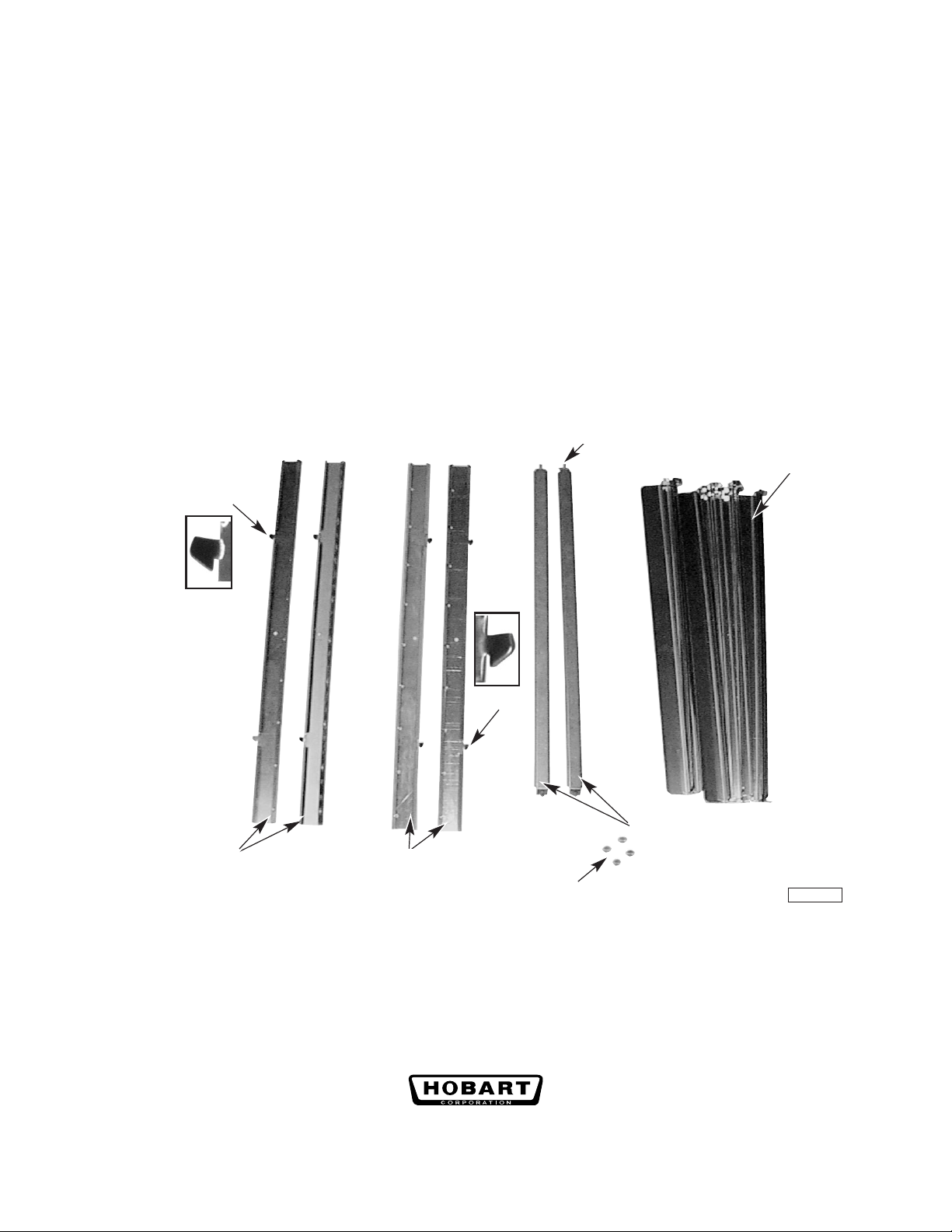
THREADED STUD
CF1 PAN SLIDES
HOOK
HOOK
RIGHT FRONT
LEFT REAR
WING ADAPTERS
LEFT FRONT
RIGHT REAR
WING ADAPTERS
KNURLED NUTS
Fig. 1
LOCKING BRACE
PL-41587-1
1. Identify the parts from the list and Fig. 1. Place the flat side of the Wing Adapters down so the ribs
are up. Group the two Wing Adapters with the left hooks together. Group the two Wing Adapters
with the right hooks together. Refer to Fig. 1 to determine which pair is for the Right Front and Left
Rear; the other pair is for the Left Front and Right Rear.
701 S. RIDGE AVENUE
TROY, OHIO 45374-0001
937 332-3000
www.hobartcorp.com
FORM 34719 (Dec. 2001)
Page 2
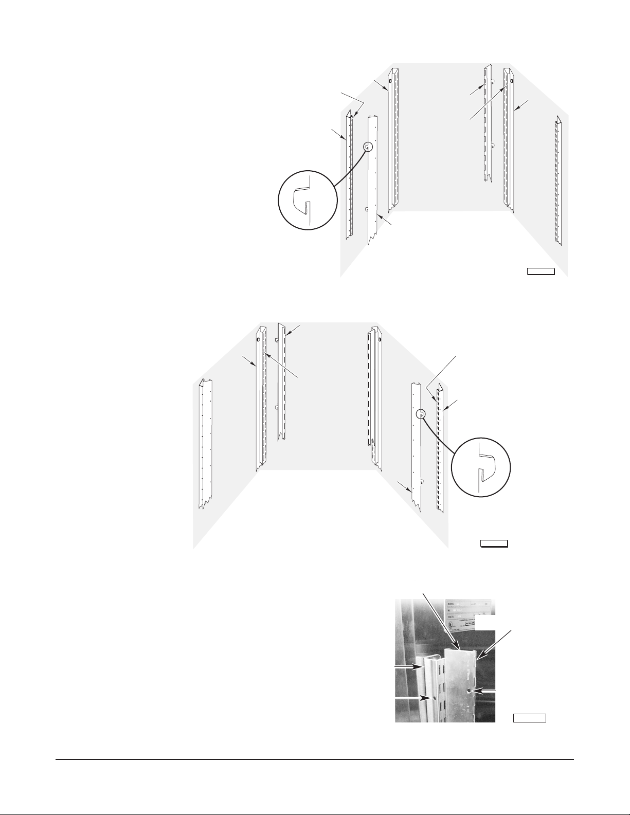
2. Assemble the Left Front and Right Rear
Wing Adapters (281525-1) onto the Left
Front and Right Rear Pilasters inside the
cabinet (Fig. 2).
3. Assemble the Right Front and Left Rear
Wing Adapters (281525-2) onto the Right
Front and Left Rear Pilasters inside the
cabinet (Fig. 3).
NOTE: Each Pilaster has two columns of
slots (Figs. 2, 3). Slide the Hooks on the
Front Wing Adapters into the rear column
of slots on the Front Pilasters (Figs. 2, 3).
Similarly, slide the Hooks on the Rear
Wing Adapters into the front column of
slots on the Rear Pilasters.
HOOK INTO
REAR SLOT
LEFT FRONT
PILASTER
HOOK
LEFT REAR
WING ADAPTER
LEFT REAR
PILASTER
RIGHT REAR
WING ADAPTER
HOOK INTO
FRONT SLOT
LEFT FRONT
WING ADAPTER
RIGHT REAR
PILASTER
PL-56145
Fig. 2
LEFT REAR
PILASTER
HOOK INTO
FRONT SLOT
Fig. 3
4. Use the Pilaster Holes and the Wing Adapter Holes
(Fig. 4) as a reference to keep all Wing Adapters at the
same height.
RIGHT FRONT
WING ADAPTER
FRONT LEFT
PILASTER
PILASTER
HOLE
HOOK INTO
REAR SLOT
RIGHT FRONT
PILASTER
HOOK
PL-56146
WING ADAPTER
VERTICAL SLOTS
WING
ADAPTER
HOLE
PL-41588-1
Fig. 4
© HOBART CORPORATION, 2001
– 2 –
Page 3
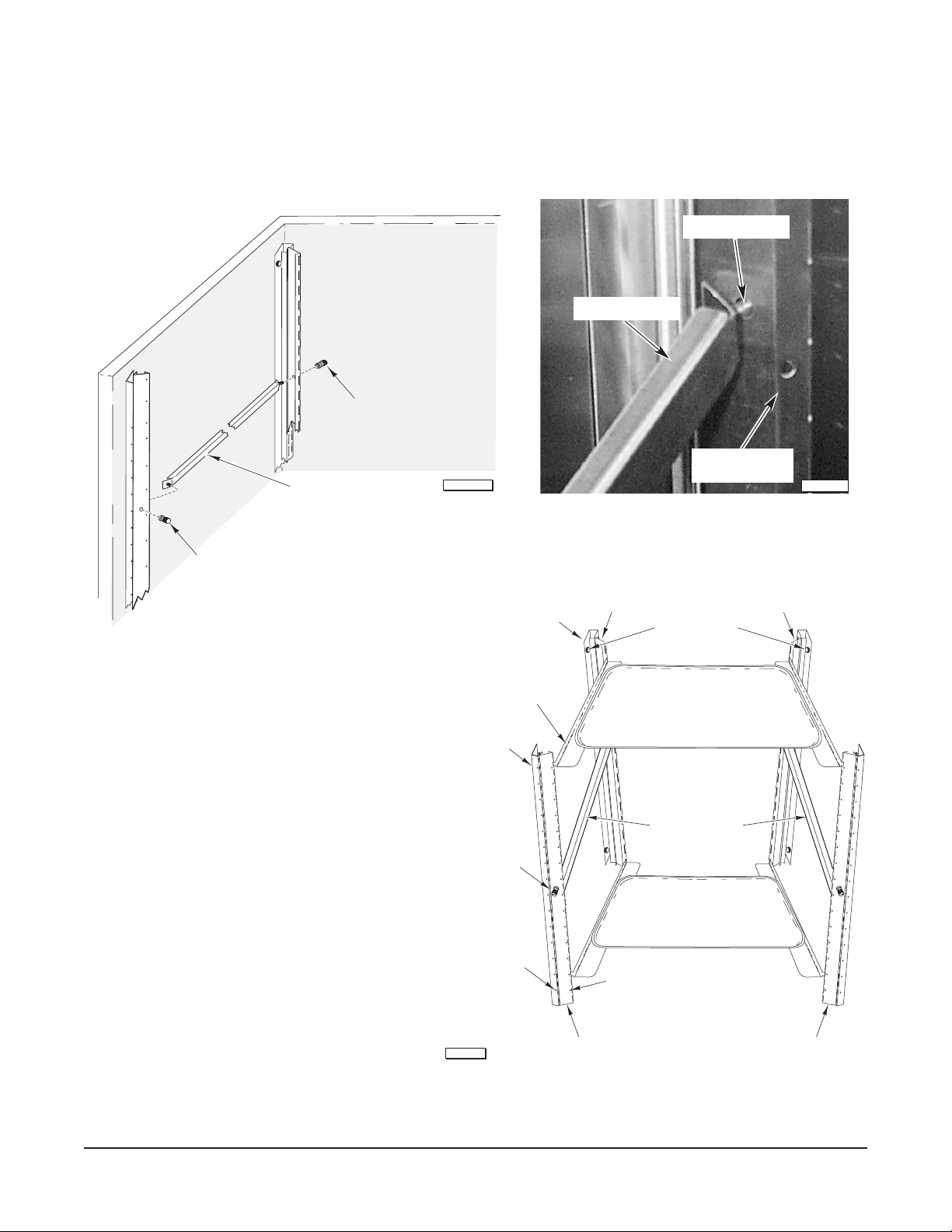
5. On each side, assemble one Locking Brace at the vertical midpoint between the Front and Rear Wing
Adapters by inserting the Threaded Studs on the Locking Brace through the large holes in the middle
of the Wing Adapters (Figs. 5, 6).
6. Screw the Knurled Nuts onto the Threaded Studs of the Locking Braces; but, keep the Knurled Nuts
loose until step 9.
THREADED STUD
LOCKING BRACE
KNURLED NUT
LEFT REAR
LOCKING BRACE
PL-56147
WING ADAPTER
PL-41592-1
Fig. 6
KNURLED NUT
Fig. 5
7. If it is necessary to reposition the Front
and Rear Pilasters for proper fit of the
Locking Brace — loosen the
Thumbscrews (Fig. 7) that mount the
Pilasters to the cabinet interior, slide
the Pilasters forward or backward on
the slots as necessary and retighten
the Thumbscrews.
PILASTER
LEFT REAR
CF1 PAN SLIDE
PILASTER
LEFT FRONT
KNURLED NUT
PILASTER HOLE
WING ADAPTER
LEFT REAR
WING ADAPTER
HOLE
WING ADAPTER
RIGHT REAR
THUMBSCREW
LOCKING BRACE
PL-55805
– 3 –
WING ADAPTER
LEFT FRONT
Fig. 7
WING ADAPTER
RIGHT FRONT
Page 4
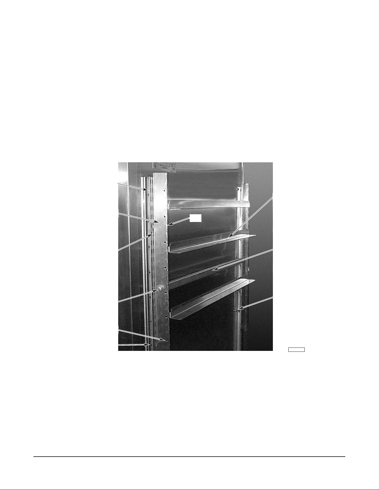
8. Assemble the CF1 Pan Slides into the vertical slots of the Wing Adapters (tabs rotate up into vertical
slot and then drop down to seat). Allow for the height of the pans when placing the CF1 Pan Slides.
Use the Pilaster Holes and the Wing Adapter Holes to keep the CF1 Pan Slides level, left-to-right and
front-to-rear (Figs. 7, 8).
9. Completely tighten the four Knurled Nuts to securely fasten the Locking Braces to the Wing Adapters.
Use your fingers to tighten the Knurled Nuts so they can be disassembled for cleaning.
10. Use the Pilaster Holes and the Wing Adapter Holes (Figs. 4, 7, 8) to keep the Pan Slides level (Fig. 8).
PILASTER
PAN SLIDE
WING ADAPTER
SLOT
KNURLED NUT
WING ADAPTER HOLE
PILASTER HOLE
SLOT
LOCKING BRACE
THUMB SCREW
PL-41593-1
Fig. 8
FORM 34719 (Dec. 2001) PRINTED IN U.S.A.
– 4 –
 Loading...