

Page 1
REV. 29.09.2008
Starting from Serial No.:
8658 0001
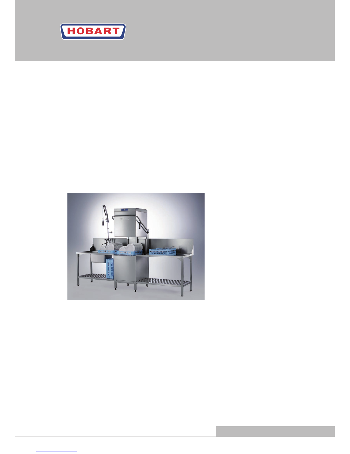
AM900
GLASS AND DISHWASHERS
INSTALLATION AND
OPERATION INSTRUCTIONS
Page 2

2 AG-21590-A-09-08
DE
GB
F
NL
Page 3

AG-21590-A-09-08 3
DE
GB
F
NL
CONTENT Page
1 IMPORTANT NOTES ...................................................................... 4
2 INSTALLATION .............................................................................
5
2.1 Location ...................................................................................... 5
2.2 Converting to corner operation ...................................................... 5
2.3 Electrical connection ..................................................................... 6
2.4 Water connection .......................................................................... 6
2.5 Drain connection .......................................................................... 6
3 CONNECTING A POWDER OR SOLID DETERGENT DISPENSER ........
7
4 CONTROLS ..................................................................................
8
5 START-UP .....................................................................................
9
5.1 Detergent / rinse aid ..................................................................... 9
5.2 Priming the suction hoses ............................................................. 9
5.3 Softener (only on option) ............................................................. 10
6 OPERATION ...............................................................................
11
6.1 Preparation ................................................................................ 11
6.2 Run ........................................................................................... 11
6.3 Program selection ...................................................................... 12
7 SWITCH-OFF AND CLEANING THE MACHINE ................................
13
7.1 Switch-off ................................................................................... 13
7.2 Cleaning (daily) ........................................................................... 13
7.3 Cleaning (weekly) ........................................................................ 13
8 PREVIEW OF TEMPERATURES .....................................................
14
9 FAULTS ......................................................................................
14
10 SETTINGS AND COUNTER VALUES ..............................................
15
10.1 Adjustment of detergent dosage quantity ...................................... 15
10.2 Adjustment of rinse aid dosage quantity ....................................... 15
10.3 Adjustment of water hardness .................................................... 15
10.4 Cycle counter ............................................................................. 16
10.5 Water consumption counter ......................................................... 16
10.6 Remaining water quantity counter for external water treatment ....... 16
10.7 Termination of setting mode / counter display .............................. 16
11 FROST PREVENTION ..................................................................
17
12 MAINTENANCE ..........................................................................
17
13 TROUBLESHOOTING GUIDE .........................................................
17
Page 4

4 AG-21590-A-09-08
DE
GB
F
NL
1 IMPORTANT NOTES
Use in Accordance with Regulations
This machine is exclusively to be used to wash ware such as plates, cups, glasses, cutlery, trays etc.
Do not use for electrically heated cooking and heat conservation appliances.
Safety
Never hose down the machine.
The "Attention" symbol is shown beside instructions that are essential for the
safe operation of the machine.
Please read these passages thoroughly.
Liability
Installations and repairs which are carried out by non authorized technicians or the use of other than
original spare parts, and any technical alterations to the machine, may affect the warranty set
out in the standard conditions of sale.
Machine noise level:
The machine noise level is ≤ 70 dB (A).
Page 5
AG-21590-A-09-08 5
DE
GB
F
NL
2.1 LOCATION
Rear wall clearance not required.
For corner installation lateral clearance of 107 mm is required.
For free-standing installation the optional rear panel has
to be installed.
Level machine by turning the feet.
Distribute machine weight equally onto all feet.
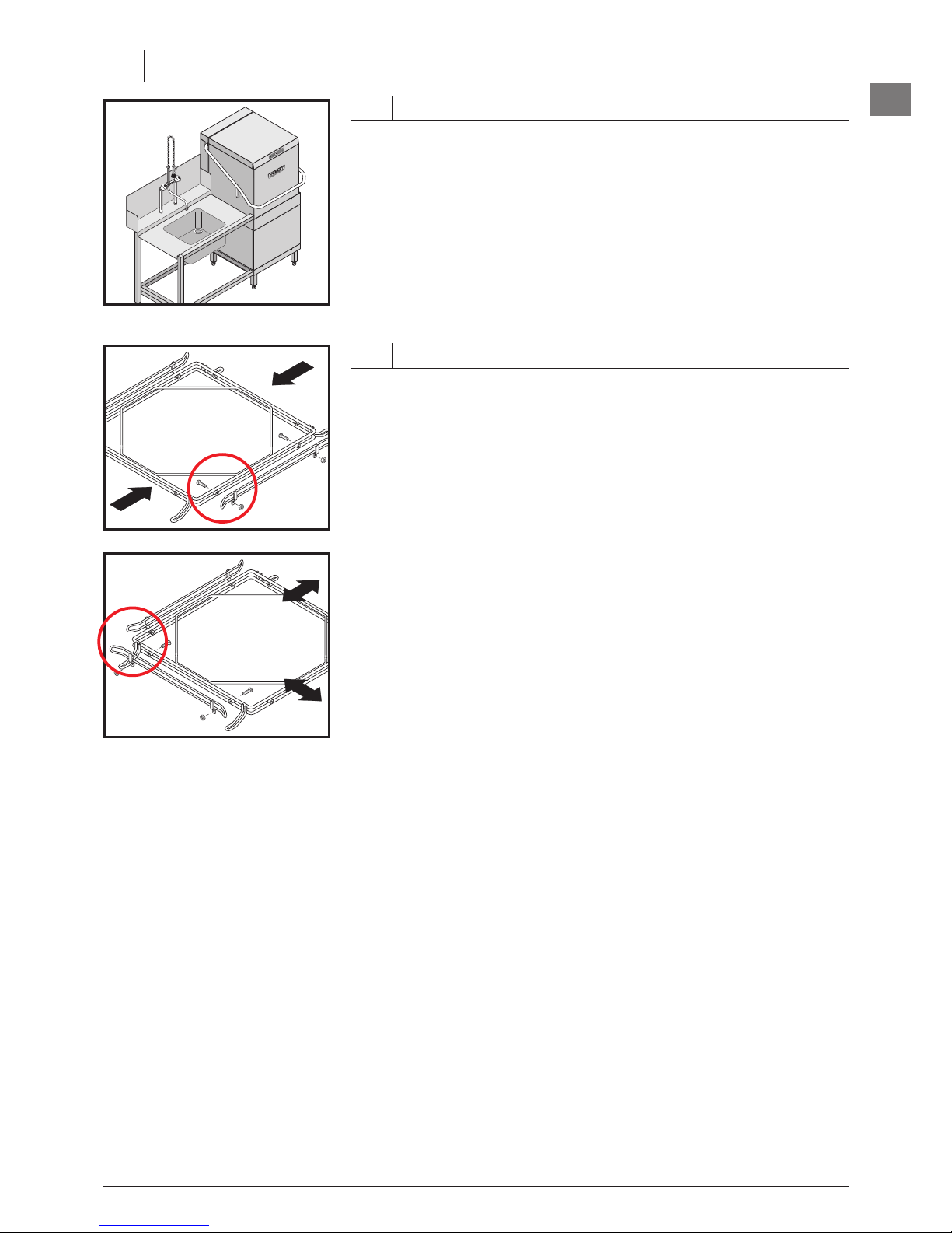
2.2 CONVERTING TO CORNER OPERATION
Depending on direction of operation, the guide rails may need to be
adjusted to suit the direction of operation (see arrows).
Unscrew the guide rail in front.
Refit guide rail at right angle according to the direction of operation.
–
–
–
–
–
2 INSTALLATION
Page 6
6 AG-21590-A-09-08
DE
GB
F
NL
max. 750 mm
A
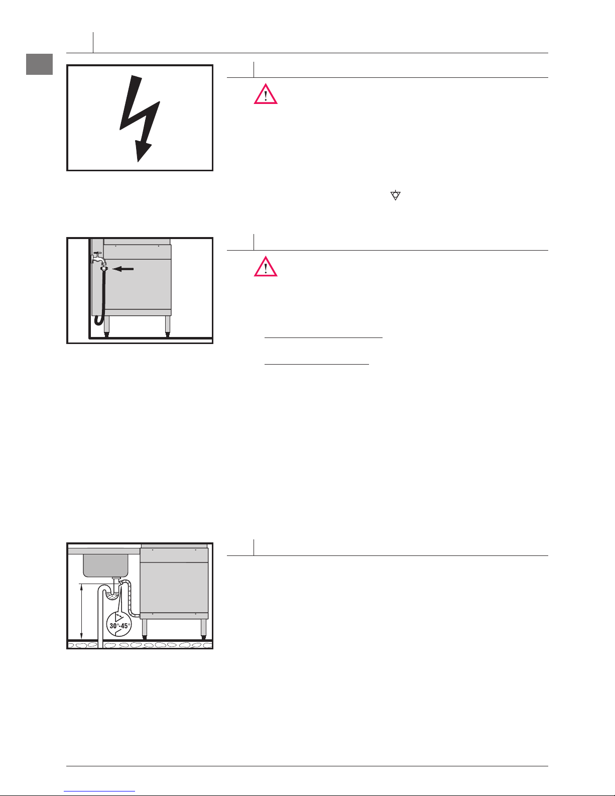
2.3 ELECTRICAL CONNECTION
Must be carried out by an authorized technician according
to the local and national codes.
The electrical supply shall comply with the name-plate data.
Line fuses and cable cross section shall comply with the requirements.
A cut-off device shall be provided to connect the supply cord (isolating
switch or accessible plug device).
According to EN 60 335 the appliance must be connected to an equipotential
conductor. The connecting screw ( ) is located beside the cable inlet.
2.4 WATER CONNECTION
Must be carried out by an authorized technician according
to the national and local codes.
The machine must be operated with potable water.
For water with an extremely high mineral content an external
demineralisation is strongly recommended.
Machines without softener: Connect to soft and if possible warm
water (up to 4° Clark = 0.5 mmol/l, max. 60°C).
Machines with softener: Connect to warm water (max. 60°C) if
possible.
Line flow pressure 0.5 – 10 bar.
Important: the line flow pressure must not be less than 0.5 bar.
If the line flow pressure is above 10 bar provide pressure reducer
at source.
Connect the union nut "A" (3/4") of the water supply hose to the site
shut off valve.
Do not kink or cut the supply hose.
If an extended supply hose is required, use one of the same
specifications as the original.
2.5 DRAIN CONNECTION
Connection between machine and site drain must not exceed max.
height of 0.75 m.
Do not place the drain hose loosely on the floor (the hose could be
rubbed through). Fix it at site!
Do not kink the drain hose.
–
–
–
–
–
–
–
–
–
–
–
–
INSTALLATION
Page 7

AG-21590-A-09-08 7
DE
GB
F
NL
Must be carried out by an authorized technician according
to the local and national codes.
Tank must be drained.
Switch off main switch or unplug.
Remove front panel and the left hand or right hand side panel
(according to requirement on site).
Lift up control box and turn it to front.
Break out perforated disk at the tank panel (either at the right or left
side).
Drill a hole through the inner tank wall appropriate to the required
connection diameter.
Screw up tightly the dosing connection with tank wall.
Connect the plug (A) of the wire harness with the dosage pump
(max. 100 VA).
Close control box and put panels back into place.
Switch on main switch at site or put the plug in.
Dispenser adjustment see chapter 10.1.
CONDUCTIVITY PROBE:
Conductivity probe should be installed at the flat part of tank bottom
(see fig.).
The hole size should be appropriate to the conductivity probe.
Important:
Remove drilling chips thoroughly to prevent corrosion.
–
–
–
–
–
–
–
–
–
–
–
–
3 CONNECTING A POWDER OR SOLID DETERGENT DISPENSER
ca.120mm
ca.120mm
A
Page 8

8 AG-21590-A-09-08
DE
GB
F
NL
➀
Machine ON / OFF
Pushing this button switches the machine on.
By pushing and holding (3 seconds) this button, the drain and self
cleaning cycle starts. At the end of the cycle, the machine switches off
automatically.
After switch off, the machine is not voltage free!
Furthermore the button illuminates to indicate the mode of the machine:
GREEN
GREEN
(flashing)
(permanent)
= Machine is filling and heating.
Wash cycle is running.
Machine is draining / switches off.
= Machine is ready for operation.
➁
Program button
By pushing this button, it is possible to select between different preset
programs, according to the model and equipment.
The program no. (e.g. P02) will be shown in the Display ➄.
➂
Stop button
In case of operating error or faults, it is possible to switch-off the
machine immediately without the drain cycle, by pushing this button.
After switch off, the machine is not voltage free!
➃
Display e.g. temperature indication Wash (°C) (see chapter 8).
➄
Display e.g. temperature indication Rinse (°C) (see chapter 8).
➅
Salt required
Indicating the need for regeneration salt to be added.
(Only with built-in softener.)
➆
Service indicator
Indicating, that the machine has a fault (see chapter 9).
4 CONTROLS
5
46
123
7
Page 9

AG-21590-A-09-08 9
DE
GB
F
NL
5.1 DETERGENT / RINSE AID
Use only commercial detergent and rinse aid. Please pay attention to
the manufacturers safety instructions.
The dosing pumps can operate to a maximum head height
of 1.5 m. Do not confuse the containers !
5.1.1
DETERGENT
Do not use any acidic detergent products with the built-in detergent
pump! (The ph-value has to be higher than 7.)
Place the suction hose into the external detergent container.
Fill the suction hose according to chapter 5.2.
5.1.2
RINSE AID
Place the suction hose (blue marking) into the external rinse aid
container. Fill the suction hose according to chapter 5.2.
5.1.3
CHANGING THE TYPE OF DETERGENT / RINSE AID
Before changing to a different product type (even from the same
supplier), the suction hoses must be rinsed thoroughly with fresh
water (procedure as described under 5.2).
Otherwise, the mixing of different types of chemicals will cause
crystallisation, which may result in a malfunction of the dosing pump.
5.2 PRIMING THE SUCTION HOSES
We recommend the manual hose priming as follows.
ATTENTION:
The machine has to be switched off.
Open the hood.
Push Stop button ➂ and Program button ➁ simultaneously until the
upper Display ➄ shows "CH1".
Push Program button repeatedly, until "d" is displayed.
Close the hood.
In the upper Display appears "SF1", in the lower one "0".
–
–
–
–
–
–
–
–
5 START-UP
Page 10

10 AG-21590-A-09-08
DE
GB
F
NL
5.2.1 DETERGENT SUCTION HOSE
Pushing the ON/OFF button ➀ activates the hose priming for
60 seconds.
Each cycle can be interrupted by pushing the ON/OFF button again.
5.2.2
RINSE AID SUCTION HOSE
Push the Program button ➁.
In the upper Display ➄ appears "SF2", in the lower one ➃ "0".
Pushing the ON/OFF button ➀ activates the hose priming for
360 seconds.
Each cycle can be interrupted by pushing the ON/OFF button again.
5.2.3
TERMINATION OF HOSE PRIMING
Open hood and close it again or do not press any button for
10 seconds.
5.3 SOFTENER (only on option)
For the first run, the softener has to be filled with regeneration salt
and potable water.
Filling the salt reservoir with cleaning agent will damage
the water softener.
Open the hood.
Unscrew the softener lid and fill the softener with 2 kg of "Granular
regeneration salt" (do not use salt tablets).
Fill up the softener with potable water (only at the first run).
Clean seal and rim of softener lid carefully, before closing
the lid.
Close lid and tighten.
Adjust the water hardness according to chapter 10.3 !
When the Salt indicator ➅ illuminates during operation, the softener
has to be refilled with regeneration salt.
There will be a slight delay before salt light goes out after refill.
–
–
–
–
–
–
–
–
–
–
START-UP
Page 11

AG-21590-A-09-08 11
DE
GB
F
NL
6.1 PREPARATION
Check correct position of rack guide, wash/rinse arms and strainers.
Open shut-off valve.
Switch on main switch or put the plug in.
Check level of detergent and rinse aid containers.
Close hood and push the ON/OFF button ➀, tank will be filled.
The ON/OFF button flashes green during fill and heating cycle. This
process can take several minutes.
When the button changes to green steady burning light, machine is
ready for operation.
Place glasses and cups face downwards into the rack.
Remove any food debris before loading plates into rack.
Spray off greasy food soil.
6.2 RUN
Put rack into the machine and close the hood.
The ON/OFF button ➀ flashes green, wash cycle is running.
As soon as the ON/OFF button changes to steady green light, the
wash cycle is finished.
Open the hood and take out rack.
Allow dishes to dry for 1 minute approx.
–
–
–
–
–
–
–
–
–
–
–
–
6 OPERATION
Page 12

12 AG-21590-A-09-08
DE
GB
F
NL
To avoid heat loss, lower hood to "Stand By" position between
wash cycles.
6.3 PROGRAM SELECTION
The machine is operating automatically with standard cycle time.
If needed, it is possible to select a shorter or longer program.
To show the present program, push the Program button ➁ before
starting the wash cycle.
To change the program, push the Program button again.
P 01
=
Short cycle (for light / medium soiled dishes and glassware)
P 02
=
Standard cycle (for medium / heavy soiled dishes)
P 03
=
Long cycle (for dried on soiling and containers)
The machine continues with the chosen cycle time until it is switched
off or another program is chosen.
–
OPERATION
Page 13

AG-21590-A-09-08 13
DE
GB
F
NL
7.1 SWITCH-OFF
Close the hood.
Push and hold (min. 3 seconds) the ON/OFF button ➀.
The button flashes green during the drain cycle.
NOTE:
During the drain cycle, the interior of the machine is cleaned automatically.
A final inspection is recommended to remove any food debris.
When the ON/OFF button goes off:
Switch off main switch or unplug and close the shut-off valve!
7.2 CLEANING (DAILY)
To clean the machine do not use any chloric, acidic or
abrasive products and no metallic brushs.
Open hood and take out rack guide.
Take out strainers and flush.
Please ensure that food debris does not enter pump intake
!
Clean interior of the machine.
Put strainers and rack guide back into place.
Leave hood open for ventilation.
7.3 CLEANING (WEEKLY)
Take out rack guide.
Loosen the retaining screws (A) by turning them counter-clockwise.
Take out and clean wash and rinse arms.
–
–
–
–
–
–
–
–
–
–
7 SWITCH-OFF AND CLEANING THE MACHINE
Page 14

14 AG-21590-A-09-08
DE
GB
F
NL
CODE POSSIBLE CAUSE MEASURES
AL
Drain hose blocked. Restart drain cycle. Clean drain hose if necessary.
HEI
Rinse booster heating defective. Call the after sales service.
d 0
OPTION
External demineralisation cartridge depleted. Replace cartridge.
SAL
Salt deficiency
(only with built-in softener).
Refill the softener with granular regeneration salt.
The Service indicator ➆ is illuminated and:
CODE POSSIBLE CAUSE MEASURES
FIL
Shut-off valve is closed. Open shut-off valve at site and switch on machine again.
Fill valve or fill system defective. Call the after sales service.
SIE
Tank strainer not correctly positioned. Put strainer correctly in place.
UL
Drain hose blocked. Clean drain hose and restart drain cycle.
Fill system or drain system defective. Call the after sales service.
F01
Temperature probe "rinse booster" defective. Call the after sales service.
F02
Temperature probe "tank" defective. Call the after sales service.
F03
Pressure transmitter "rinse booster" defective. Call the after sales service.
F04
Pressure transmitter "tank" defective. Call the after sales service.
OTHER INDICATIONS
Moving light point in the upper display:
CODE CAUSE MEASURES
. . .
Softener regeneration active (only with built-in
softener).
None.
According to the fault, an error code will be shown in the upper
display ➄ (see table below).
Please report the error code to the service technician.
–
9 FAULTS
Press and hold (3 seconds) the Program button ➁ until the actual
temperatures (°C) are displayed (top = rinse, bottom = wash).
The indicators go out 10 seconds after releasing the Program button.
Permanent temperature display can be activated on request by the
service technician.
–
–
8 PREVIEW OF TEMPERATURES
Page 15

AG-21590-A-09-08 15
DE
GB
F
NL
ATTENTION:
The machine has to be switched off.
Open the hood.
If the hood will be closed or if no button is pressed for 10 seconds,
the indicator automatically switches off and the new settings will
be saved.
Therefore the setting procedure can be interrupted at any time.
10.1 ADJUSTMENT OF DETERGENT DOSAGE QUANTITY
Push Stop button ➂ und Program button ➁ simultaneously until in
the upper Display ➄ "CH1" appears.
In the lower Display ➃ appears e.g.:
"8" = pre-adjusted value of the detergent dosage time =
8 s ≈ 2.0 g/l.
To adjust the detergent dosage time, push ON/OFF button ➀
repeatedly, until the desired value (0-50 s ≈ 0-15.4 g/l) appears.
Adjustment should be done in accordance with chemical suppliers
recommendations.
10.2 ADJUSTMENT OF RINSE AID DOSAGE QUANTITY
Push Program button ➁ again.
In the upper Display ➄ appears "CH2".
In the lower Display ➃ appears e.g.:
"7.0" = pre-adjusted value of the rinse aid dosage time =
7.0 s ≈ 0,31 g/l.
To adjust the rinse aid dosage time, push ON/OFF button ➀
repeatedly, until the desired value (0-50 s ≈ 0-2.2 g/l) appears.
Adjustment should be done in accordance with chemical suppliers
recommendations.
10.3 ADJUSTMENT OF WATER HARDNESS
With optional softener only.
To adjust the softener to the local water hardness (obtain details from
local water authority:
Push Program button ➁ repeatedly until in the upper Display ➄
"H02" appears.
Push ON/OFF button ➀ repeatedly, until the required value (H01-H04)
will be displayed.
H01
= up to 9 °eh / H02 = 10 to 18 °eh / H03 = 19 to 26 °eh /
H04 = 27 to 38 °eh water hardness (°eh = Clark).
–
–
–
–
–
–
–
–
10 SETTINGS AND COUNTER VALUES
Page 16

16 AG-21590-A-09-08
DE
GB
F
NL
10.4 CYCLE COUNTER
Push Program button ➁ again.
The display will show alternately "P" or the number of wash cycles.
In the lower Display ➃ appears the value up to 999.
Thousands will be shown in the upper Display ➄.
Example: 1023 wash cycles
Max. indication:
999 999
10.5 WATER CONSUMPTION COUNTER
Push Program button ➁ again.
The display will show alternately "E" or the water consumption (liter).
In the lower Display ➃ appears the value up to 999 liter.
Thousands will be shown in the upper Display ➄.
Example: 10217 liter
Max. indication:
999 999
10.6 REMAINING WATER QUANTITY COUNTER
FOR EXTERNAL WATER TREATMENT
(Only available if activated in service mode (S18). The capacity
(liter) of the water treatment has to be stored via C79/80.)
Push Program button ➁ again.
The display will show alternately "d" and/or the remaining water quantity
(liter).
In the lower Display ➃ appears the value up to 999 liter.
Thousands will be shown in the upper Display ➄.
Example: 1586 liter
Max. indication:
999 999
To reset the counter to pre-set value, push and hold (3 seconds) the
ON/OFF button ➀.
10.7 TERMINATION OF SETTING MODE / COUNTER DISPLAY
Open the hood and close it again or do not press any button for
10 seconds.
–
–
–
–
–
SETTINGS AND COUNTER VALUES
Page 17

AG-21590-A-09-08 17
DE
GB
F
NL
In case of frost or longer operation pauses (e.g. for seasonal operations)
the machine must be completely drained.
This should be carried out by after sales service.
Reset for operation according to chapter 5.
For trouble free operation we recommend you enter into a service
contract with your local Service Office.
11 FROST PREVENTION
12 MAINTENANCE
13 TROUBLESHOOTING GUIDE
TYPE OF FAILURE POSSIBLE CAUSE REMEDY
Poor wash result
Dishes are not clean. Wash arms stiff (you should be able to
turn them easily by hand).
Take out wash arms and clean them thoroughly.
Check water outlet from machine to wash arms is
clear.
Wash arm nozzles are clogged
(visual check).
Take out wash arm, remove cleaning cap and rinse
wash arm thoroughly until soil is removed.
Replace correctly.
Rinse arm nozzles are clogged
(possibly by lime deposit)
Remove rinse arms and decalcify them in separate
container.
Detergent concentration is too low or too
high.
Check setting of detergent concentration.
See also operating instructions point 10.1.
Coarse strainer soiled. Take out strainer, empty and clean it.
Fine strainer soiled or obstructed by
lime.
Take out fine strainer. If heavily soiled soak in a
vinegar solution. Then clean it thoroughly until the
pores are free.
Cleaning is to be done daily (see operating
instructions).
Wrong program selected for heavily
soiled dishes.
Select program with longer wash cycle.
Dishes or glasses do not dry
properly.
Rinse aid concentration too low. Increase concentration.
See also operating instructions point 10.2.
Dishes still greasy. Detergent concentration too low: increase
(see instructions).
Check if detergent is appropriate. If not choose
a stronger one.
Drain soiled water and refill machine.
Check pre-scrapping procedure.
1.
2.
3.
Rack is not suitable for type of dishes
(sloping).
Use appropriate racks to create a sloping position
which allows water to drain away from cavities.
Dishes stay too long in the machine at
the end of program.
Take out dishes as soon as cycle is completed to
enable them to dry.
Page 18

18 AG-21590-A-09-08
DE
GB
F
NL
If no button will be pressed during 6 hours, the machine switches off automatically without draining.
TROUBLESHOOTING GUIDE
TYPE OF FAILURE POSSIBLE CAUSE REMEDY
Poor wash result
Stripes and staines on
dishes or glasses.
Rinse aid concentration too high. Reduce quantity (see instructions).
Hard water or high mineral content. Check water quality.
Obtain details from local water authority.
Recommended values:
Ideal degree of hardness is 4° Clark.
Ideal conductivity value for glasses is
max. 150 µS/cm and for dishes max. 400 µS/cm.
Rack is not suitable for type of dishes
(sloping).
Use appropriate racks to create a sloping position
which allows water to drain away from cavities.
Insufficient rinse aid concentration
causes staines
Increase quantity (see instructions)
Machine with softener:
Wrong type of salt used.
Use only granular regeneration salt.
Other malfunctions
Glasses are totally or
partially cloudy
Surface of glasses is rough and
porous, this is called glass corrosion
This is not caused by a malfunction on the
machine. Replace with new glasses.
Glass breakages. Use of inappropriate dish or glass racks. Use appropriate racks.
Machine suddenly stops
during wash program.
Machine is connected to a "maximum
power supply unit" which cuts out the
energy consumer at a given point, or machine is interlocked with another energy
consumer unit.
Connect machine separately (call electrician).
Blown site fuse. Check site fuses.
Page 19

AG-21590-A-09-08 19
DE
GB
F
NL
Page 20

As continued product improvement is a policy of HOBART, specifications are subject to change without notice.
Printed in Germany AG-21590-A-09-08-PC
 Loading...