

Page 1

AM3 Dishwasher installation and
operation manual
Hobart Food Equipment Co., Ltd.
FORM 743423-2E
Page 2

TABLE OF CONTENTS
GENERAL……………………………………………………………1
INSTALLATION……………………………………………………2
Location……………………………………………………………………………2
Convert from straight-through to corner operation………………………3
Electrical connections……………………………………………………………4
Plumbing connections……………………………………………………………6
OPERATION………………………………………………………7
Controls……………………………………………………………………………7
Preparation…………………………………………………………………………7
Dishwashing………………………………………………………………………8
MAINTENANCE……………………………………………………9
MACHINE CLEANING……………………………………………9
TROUBLESHOOTING……………………………………………10
Appendix 1: Circuit Diagram
Appendix 2: Electrical Wiring Connection Layout
Appendix3: Installation guide
Appendix4: Control board chart
Page 3
AM3 Dishwasher Installation & Operation Manual
Installation, Operation, and Maintenance of
AM3 DISHWASHERS
SAVE THESE INSTRUCTIONS
GENERAL
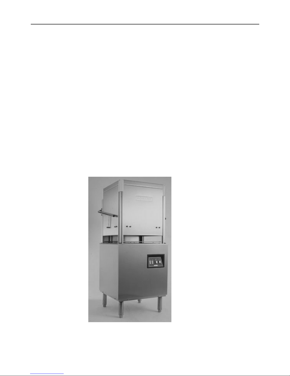
The AM3 dishwashers are semi-automatic rack-type machines. Three doors open at the same
time to allow the rack to be pushed in or out. After filling, an automatic wash and rinse cycle
begins when the door is lowered.
Dish table heights may be specified at time of order for 800mm (31.5 inches) or 860mm (33.875
inches).
Electric booster heat options (7kW or 14kW) include an open vented booster tank supplied with a
solenoid valve, line strainer, rinse pump and type “A” air gap. Low water protection is provided in
the boosters. No booster versions are also available for connection to external heating.
1
Page 4
AM3 Dishwasher Installation & operation Manual
INSTALLATION
Before installing, check the electrical service to be sure it agrees with the electrical specifications
on the data plate located on the right side of machines.
Immediately after unpacking, check for possible shipping damage. If the dishwasher is found to
be damaged, save the packaging material and contact the carrier or supplier within 15 days of
delivery.
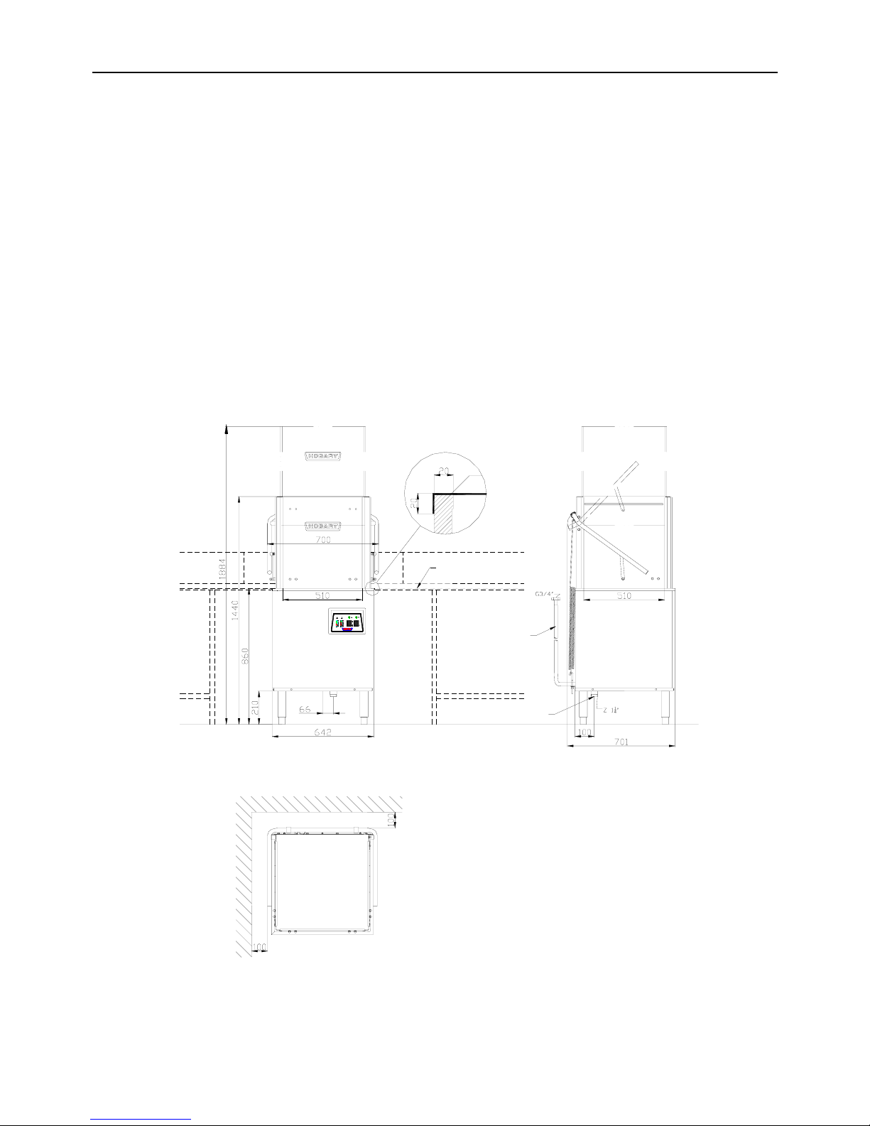
LOCATION
Place the dishwasher in its operating location. Before finalizing the location, make sure that
consideration has been given for the electrical conduit, water supply, drain connection, gas
booster location (if applicable), tabling, chemical feeder replenishment (if applicable), daily
cleaning, maintenance and adequate clearance for opening the doors (Fig. 1).
WALL
WALL
THE SPACE BETWEEN WALL AND MACHINE IS AT LEAST 100 MM
DISH TABLE
DRAIN
FILL HOSE
Fig1
2
Page 5
AM3 Dishwasher Installation & Operation Manual
The dishwasher must be level before any connections are made. Turn the leveling feet as
required to level the machine and adjust to the desired height.
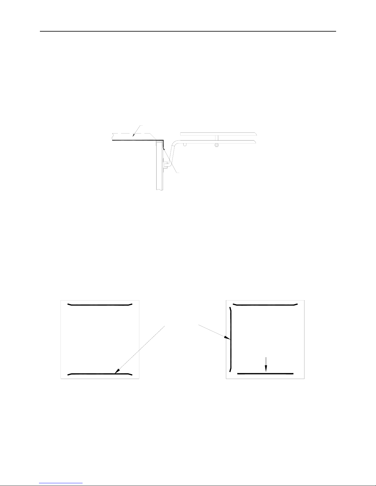
Dish table should be turned down and fitted into the dishwasher (Fig.2). Use a suitable sealer
between table and tank lip to prevent leakage.
A hood or vent may be required in order to meet local codes. The ventilation volume should be
more than 2.8m3/min in case of using hood or vent (supplied by others).
SEAL TO PREVENT
LEAKAGE
DISH TABLE
Fig. 2
CONVERT FROM STRAIGHT-THROUGH TO CORNER OPERATION
For corner operation, remove the rack guide and baffle (Fig.3) from the front, assemble the rack
guide on the side and use screws to re-install the baffle in the front.
STRAIGHT-THROUGH
CORNER
RE-INSTALL
BAFFLE HERE
RACK GUIDE
Fig. 3
3
Page 6
AM3 Dishwasher Installation & operation Manual
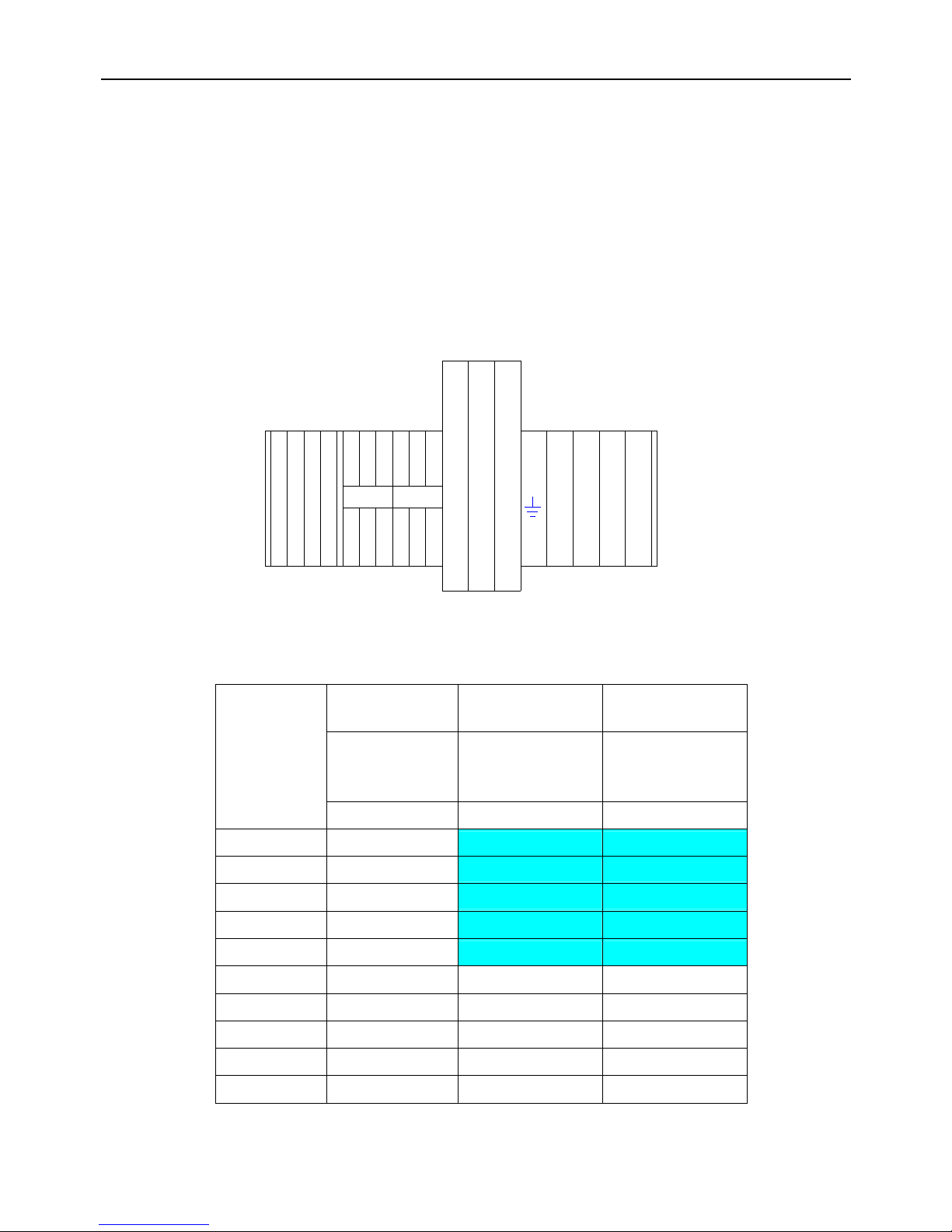
ELECTRICAL CONNECTIONS
WARNING: ELECTRICAL AND GROUNDING CONNECTIONS MUST COMPLY WITH
APPLICABLE PORTIONS OF THE NATIONAL ELECTRICAL CODE AND/OR OTHER
LOCAL CODES.
WARNING: DISCONNECT THE ELECTRICAL POWER SUPPLY AND PLACE A TAG AT
THE DISCONNECT SWITCH INDICATING THAT YOU ARE WORKING ON THE CIRCUIT.
Refer to the electrical diagram on the inside of side panel. Connect the electrical supply wires
with different colors to terminal block (Fig. 4).
Electrical Data
No Booster
7KW Electrical
Booster
14KW Electrical
Booster
Min. Circuit
Ampacity / Max.
Protective Device
Min. Circuit
Ampacity / Max.
Protective Device
Min. Circuit
Ampacity / Max.
Protective Device
Volts / Hz / Ph
AMPS AMPS AMPS
100/50/1 60
100/60/1 60
220/50/1 25
220/60/1 25
240/50/1 25
200/50/3 15 30 50
200/60/3 15 30 50
220/60/3 15 40 60
380/60/3 15 25 40
380~415/50/3 15 25 40
RPS1
RPS2
DPS1
DPS2
2FU
1FU
3FU
L1L3NL2
Fig. 4
4
Page 7

AM3 Dishwasher Installation & Operation Manual
CHECK ROTATION (Three-Phase Machines Only)
Three phase motors must rotate in the direction of the arrow on the pump housing
(counterclockwise). If the rotation is incorrect, DISCONNECT ELECTRICAL POWER SUPPLY
and interchange any two of the incoming power supply leads. Re-energize the dishwasher and
verify correct rotation.
Warning: The rotation of motors must be checked again before the first operation.
In-correct rotation could cause improperly operation of dishwasher and damage of
wash pump even in short period of time.
Power Supply for Detergent Dispenser and/or Rinse/Sanitizer Feeder (by others)
Terminals DPS1 and DPS2 in the control box allow connection of a detergent dispenser (by
others). RPS1 and RPS2 terminals allow connection of a rinse/sanitizer feeder (by others) with
maximum current of 3 Amps (Fig. 4). DPS1-DPS2 is powered during the wash cycle;
RPS1-RPS2 is powered during the rinse cycle. Refer to the electrical diagram on the inside of
side panel.
Note 1: All connecting wires must accommodate the movement of the control box as it
slides out for service.
Note 2:All wires must be 600 volts insulation cable; do not use normal low voltage cable.
Cycle Timing Data
Whole Cycle(s) 60 90 120
Wash(s) 44/47 74/77 104/107
Dwell(s) 4 4 4
Rinse(s) 12/9 12/9 12/9
5
Page 8

AM3 Dishwasher Installation & operation Manual
PLUMBING CONNECTIONS
WARNING: PLUMBING CONNECTIONS MUST COMPLY WITH APPLICABLE
SANITARY, SAFETY, AND PLUMBING CODES.
WATER SUPPLY
Connect the water pipe to the incoming water supply (3/4” NPT internal threads)
INCOMING WATER SUPPLY REQUIREMENTS
TEMPERATURE PRESSURE (Dynamic)
0
C
0
F KPa kg/cm2
With 7KW Electrical Booster 50~60 122~140 29.4~490 0.3~5
With 14KW Electrical Booster 10~60 50~140 29.4~490 0.3~5
Note: In case of line dynamic pressure is less than 0.3kg/cm
2
,a booster-pump must be
installed (by others); in case of line static pressure is more than 5kg/cm2,a pressure
reducer must be installed (by others).
DRAIN
Connect the 1
1/4” NPT drain connector under the wash tank to a suitable drain. If a grease trap is
required by code, it should have a minimum flow capacity of 95.5 liters per minute (21 gallons per
minute).
RINSE AGENT CONNECTION
Remove front panel to locate rinse agent connection
points. Two connecting points for rinse agent are
provided. One is located at the upper right side of booster
and allows rinse agent to inject into the booster tank.
Another is located under the booster tank near the rinse
pump outlet and allows rinse agent to inject into the rinse
pipe. Select a suitable point according to the chemical
requirement. Use a spanner to loosen the plug and
connect rinse agent pipe with a suitable sealing material
(Fig. 5).
G1/8" INTRERNA
L
THREADS
G1/8" INTERNAL
THREADS
Fig. 5
6
Page 9

AM3 Dishwasher Installation & Operation Manual
OPERATION
CONTROLS
Power Switch (below )
“Faucet” – power is on
“O” – power is off
Power Indicator (above )
Light on – machine power is on
Light off – machine power is off
Cycle Selector (below )
“I” – 60s wash cycle
“II” – 90s wash cycle
Working Indicator (above )
Light on – machine is working
Light off – wash cycle is finished
Temperature Display the left display indicates wash water temperature
the right display indicates rinse water temperature
Automatic Start closing the doors will automatically start a timed cycle or filling cycle.
Drain lift the standpipe to drain the wash tank
Recommended Operating Temperatures
Wash Water
60 – 65
o
C(140 – 149oF)
Rinse Water
82 – 90
o
C(181 – 194oF)
65
50
40
45
55
60
70
85
70
60
65
75
80
90
I
II O
7
Page 10

AM3 Dishwasher Installation & operation Manual
PREPARATION
Place the strainer basket in its proper location in the
corner of the wash tank and insert the stand drain
pipe (Fig. 6)
Close the doors.
Turn the power switch on, the machine will fill
automatically.
Open the door and make sure the wash tank is full
of water after fill cycle is complete. Scatter the initial
amount of detergent on the strainer basket.
Replenish as needed. If an automatic detergent
dispenser has been installed, follow supplier’s instruction.
Strainer Basket
Drain Pipe
Fig. 6
Close the door and the wash and rinse cycle will begin automatically.
Wait for the wash and rinse tank thermometer to reach the proper temperature.
DISHWASHING
Scrape the dishes to remove large particles of food and debris.
Select suitable 60 or 90 second wash cycle according to dish size and food soil.
Stack the dishes in a rack. Do not stack dishes one on top of another as water must have
free access to all sides of every dish. Stand plates and dishes up edgewise in a peg-type
rack. Cups, glasses and bowls should be inverted in an open-type or compartment type rack
(Fig. 7). Silverware and other small pieces may be scattered loosely over the bottom of a flat
bottom rack or in a basket type rack.
Fig. 7
After filling a rack, open the doors, slide the rack into the dishwasher, and close the doors.
The wash and rinse cycle will begin when the doors are closed.
When the wash and rinse cycle is finished, open the doors and remove the rack of clean
dishes. Continue by sliding in the next rack of dishes and close the doors.
If you want to add a dish after the wash cycle has started, before opening the doors, turn off
the power switch and wait 10 seconds to allow the wash arm to stop rotation to avoid hot
water splashing out on the operators.
8
Page 11

AM3 Dishwasher Installation & Operation Manual
CLEANING
It is recommended that the machine be thoroughly cleaned at the end of each working shift or at
least daily.
The procedures of machine cleaning as follow:
1 Turn of the power switch
2 Open the doors
3 Clean off the dish table into the dishwasher
4 Drain the machine by pulling out the drain stand pipe
5 Remove and empty the strainer basket and pump intake screen. Wash and rinse them
thoroughly.
6 Thoroughly clean and flush the dishwasher interior
7 Replace intake screen and strainer basket
8 Leave the doors open to allow the interior to dry
9 Check the wash and rinse arms rotate freely and are free of any obstructions
10 Check rinse nozzles to make sure they are free of any lime or obstruction
MAINTENANCE
WARNING: DISCONNECT ELECTRICAL POWER SUPPLY AND PLACE A TAG AT
THE DISCONNECT SWITCH INDICATING THAT THE CIRCUIT IS BEING WORKED
ON BEFORE BEGINNING ANY MAINTENANCE PRECEDURE.
WASHARMS
Upper and lower wash and rinse arms should turn freely and continue turning for a few seconds
after being whirled by hand. To check arms, DISCONNECT ELECTRICAL POWER SUPPLY,
rotate arms, and remove any obstructions causing improper operation.
Fig.8
Knurled Disk
Rinse Arm
Wash Arm
If the strainer basket or pump intake screen is not properly
in place, obstructions (such as food particles or bones)
may clog the wash arm nozzles. The wash arms are easily
removed for cleaning.
To remove the wash and rinse arms, unscrew the knurled
disk between the rinse and wash arms and take them out
(Fig. 8).
NOTE:
1 It is not necessary to remove the spacer located on
the lower wash arm shaft.
2 During upper wash and rinse arms removal, be careful not to drop these arms.
3 Upper and lower wash arms and rinse arms are interchangeable.
9
Page 12

AM3 Dishwasher Installation & operation Manual
TROUBLESHOOTING
This section may help you avoid a service call. However, if a symptom persists after the possible
causes have been checked, please contact HOBART local service departments.
SYMPTOM POSSIBLE CAUSES/SUGGESTED ACTIONS
No machine
operation
1 Open doors and hold for 2 seconds, close it again
2 Blown fuse or tripped circuit breaker at power supply
3 Blown fuse FU3 at control circuit
Long wash
cycle
1 Water temperature in booster is too low, fill water temperature is too
low.
2 Water in booster is below high level sensor; please examine line
strainer and solenoid valve.
Dishes not
clean
1 Wash pump rotating in wrong direction.
2 Insufficient wash water due to drain obstruction preventing proper
drain closing.
3 Insufficient water circulation due to obstruction at pump intake screen.
Disconnect power supply, drain wash tank and check.
4 Incorrect water temperature. Insufficient warm-up time. Check circuit
breaker, thermostat and heater.
5 Incorrect detergent dispensing. Contact your detergent
representative.
6 Excessive mineral deposits through wash and rinse system. Deliming
may be necessary.
Spotting
silverware,
glasses, and
dishes
1 Improperly loaded racks.
2 Incorrect rinse water temperature.
3 Loss of water pressure due to pump obstruction.
4 Excessively hardness of water.
5 Incorrect detergent for water type.
6 Incorrect rinse additive for water type.
7 Incorrect concentration of detergent, rinse additive and/or sanitizer.
Inadequate
rinse
1 Dirty line strainer causing reduced water flow. Turn off water supply,
disconnect water supply pipe and solenoid valve, withdraw and clean
screen. Reassemble.
Leaking valve
1 Foreign material preventing proper valve operation. Note: a critical
period is soon after installation when pipe compound or metal
shavings may lodge at the valve seat. Shut off supply line. Unscrew
and lift bonnet from valve body. Clean valve and reassemble
2 If a solenoid valve is malfunctioning, it is recommended that you
contact Service
No or slow fill
1 Dirty line strainer causing reduced water flow. Turn off water supply,
disconnect water supply pipe and solenoid valve, withdraw and clean
screen. Reassemble
2 Low supply line pressure
10
Page 13

AM3 Dishwasher Installation & Operation Manual
11
SERVICE
Contact your local Hobart-authorized service office for any repairs or adjustments needed on this
equipment.
Page 14

Page 15

Page 16

Page 17

Page 18

Page 19

Page 20

Page 21

Page 22

Page 23

Page 24

INCOMING WATER: Connect water line to the
supplied water hose on the back of the machine.
2.1 T he Hobart supplied incoming water hose is 1.5m long, G3/4"
internal threads.
2.2 F lowing water pressure shoukd be 0.3-5.0 kg/cm2.
2.3 Incoming water temperature shoud be 10-60C.
Note: Water pressure outside the above range will result in
ineffective rinse results.
POWER: Make electrical connection to the
machine with the Hobart supplied cord located
at the back of the machine.
3.1 Confirm that machine electrical specification are right for the
installation location.
3.2 Yellow/green wires are Ground, the blue wire in N and the
other wires are L.
Note: Electrical and ground connections must comply with
all national and local codes.
CHECK ROTATION OF WASH PUMP:
4.1 Verify counterclockwise rotation of pump after electrical
connection is completed.
4.2 If rotation is incorrect disconnect power supply and
interchange any two leads.
4.3 Re-energize the machine and verify counterclockwise pump
rotation.
RINSE AGENT DISPENSER CONNECTION :
(usually connected by chemical company)
5.1 Connect to either point (1) or point (2).
5.2 C onnections points are G1/8" internal threads.
CONNECT RINSE AGENT AND DETERGENG
POWER SUPPLY:
(usually connected by chemical
company)
6.1 Slide out control box and remove cover.
6.2 C onnect detergent dispenser wires to terminals DSP1 and
DSP2. These terminals are powered during the wash cycle
and s upply a maximum current of 3 amps.
6.3 Connect rinse agent dispenses wires to terminals RPS1
and R PS2. These terminals are powered during the rinse
cycle and supply a maximum current of 3 amps.
Note: Detergent and rinse agent dispensers can only be
connected to the terminals listed above.
DRAIN : Connect drain to the G1-1/4" external
thread drain opening on the bottom
of the machine.
THIS CARD IS A BRIEF STEP-BY STEP GUIDE FOR INSTALLING HOBART MODEL AM3.
FOR MORE INFORMATION PLEASE REFER TO THE AM3 OPERATOR MANUAL INCLUDED WITH YOUR MACHINE OR
CONTACT YOUR LOCAL HOBART SERVICE OFFICE, DEALER OR SERVICE AGENT.
1
2
3
4
5
6
AM3 Dishwasher Installation Guide
7
DISH TABLES: Dish table edge should turn down
into the dishwasher. Dish table dimensions are
detailed on the product brochure and in the
operator manual. Use a suitable sealer between
tables and tank to prevent leakage.
Page 25

AM3 CONTROL BOARD CHART
F-743441E
State of indicators
Description Indication Fill cycle Wash cycle Dwell cycle Rinse cycle Reset
Power Light means electricity turned on ON ON ON ON ON
60 sec. Light means 60 sec. working cycle selected
90 sec. Light means 90 sec. working cycle selected
120 sec. Light means 120 sec. working cycle selected
Only and must one of the three indicator is ON
Door switch Light means door closed ON ON ON ON ON/OFF
Tank low level Light means water in tank above low level sensor OFFÆON ON ON ON ON/OFF
Tank high level Light means water in tank above high level sensor OFFÆON ON/OFF ON/OFF ON/OFF ON/OFF
Booster temperature Light means water temperature in booster too low ON ON/OFF OFF OFF ON/OFF
Booster low level Light means water in booster above low level sensor ONÙOFF ON ON ON ON
Booster high level Light means water in booster above high level sensor ONÙOFF OFFÆON ON ONÆOFF ON
Wash pump Light means wash pump running OFF ON OFF OFF OFF
Rinse Pump Light means rinse pump running ONÙOFF OFF OFF ON OFF
Fill Light means fill valve open ON ONÆOFF OFF OFF OFF
Tank heater Light means water level above low water sensor OFFÆON ON ON ON ON/OFF
Booster heater Light means water level above low water sensor ONÙOFF ON ON ON ON
Indicator Light means wash in progress Flash ON ON ON OFF
Pin switch functions
ON 12 sec. rinse time
Switch 1
OFF 9 sec. rinse time
ON Thermo-stop feature is ON
Switch 2
OFF Thermo-stop feature is OFF
60'
L
N
100~220V
DC5V
-
+
+
-
0'
60'
Rinse
pump
J503
Wash
pump
J502 J504
Fill
J505
Tank
heater
J506
Booster
heater
J501
Indicator
Booster
temperature
120'90'
Power
90'
120'
off
on
2 1
J107
Booster
high level
J106
Booster
low level
J102
low level
high level
J103
Tank
J105
Tank
J101
Door swith
Pin switch
NOTE: This chart is for the use of HOBART
service technicians and service agents.
Contact your local HOBART-authorized
service office for any repairs or adjustments
needed on this e
q
ui
p
ment.
 Loading...