

Page 1

AM15 DISHWASHE R
TECHNICAL MANUAL
208-240V/60/3
SPECIFICATION SHEET
INSTALLATION INSTRUCTIONS
OPERATION INSTRUCTIONS
CLEANING INSTRUCTIONS
MAINTENANCE INSTRUCTIONS
TROUBLE SHOOTING INSTRUCTIONS
WIRING DIAGRAMS
CATALOG OF REPLACEMENT PARTS
SMARTPARTS™ USER GUIDE
RECOMMENDED SPARE PARTS LIST
Page 2

AM15 Dishwasher Technical Manual Page 2 of 83
Need other Hobart Services?
• Warranty Registration
• Delivery and Installation
• Preventive Maintenance
• Hobart Service Contracts
• Extended Warranty Contracts
• Parts and Accessories
• Specialty Programs
• Water Treatment Programs
Page 3
Item # _____________________________________
AM15 Dishwasher Technical Manual Page 3 of 83
Quantity ___________________________________
C.S.I. Section 11400
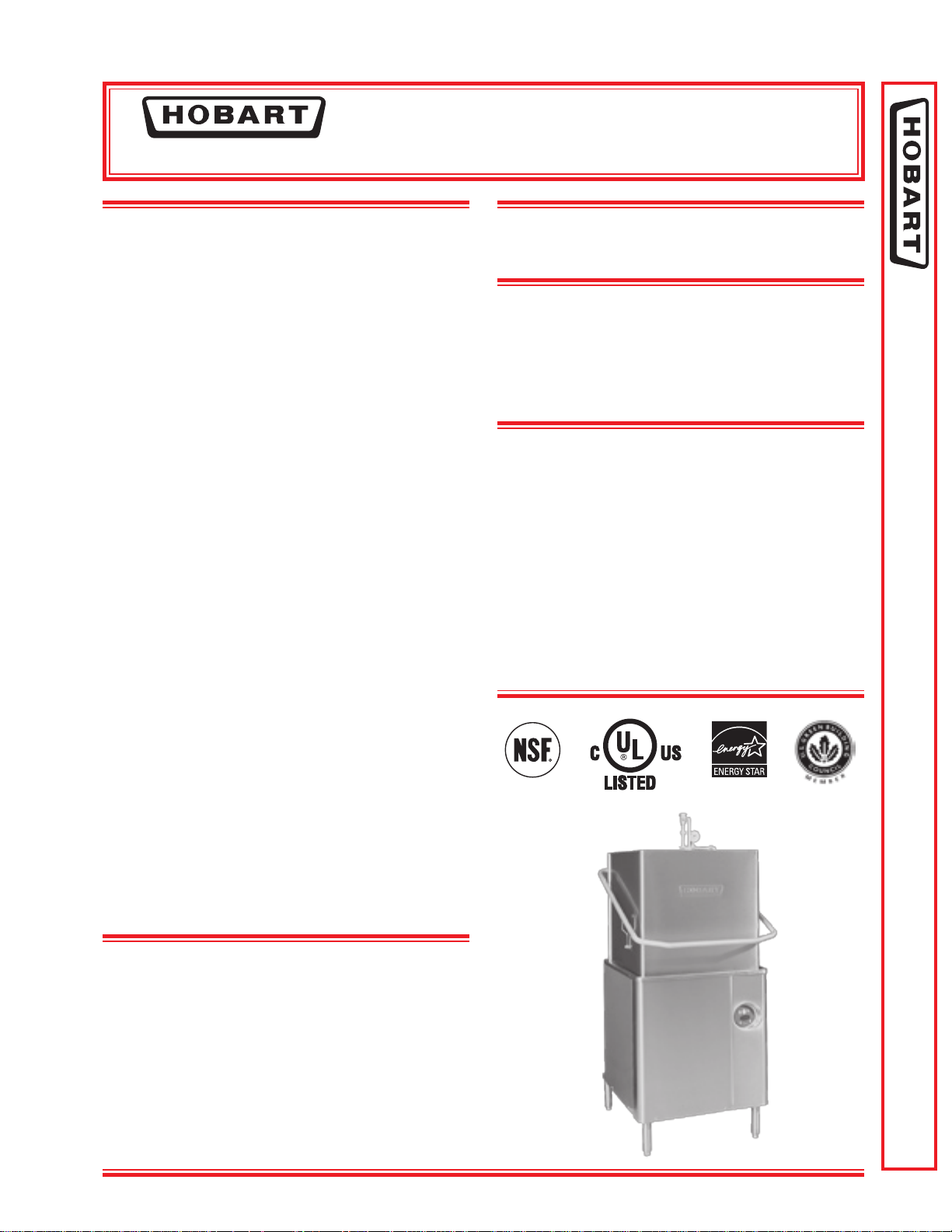
AM SELECT
701 S Ridge Avenue, Troy, OH 45374
STANDARD FEATURES
■ .74 gallons per rack nal rinse water
■ 58 racks per hour – hot water sanitizing
■ 65 racks per hour – chemical sanitizing
■ NSF pot and pan listed for 2-, 4- & 6- minute
cycles
■ Timed wash cycles for 1, 2, 4 or 6 minutes
■ Solid state, integrated controls with digital status
indicators
■ Self-draining, high efciency stainless steel pump
and stainless steel impeller
■ Stainless steel drawn tank, tank shelf, chamber,
trim panels, frame and feet
■ Spring counterbalanced chamber with
polyethylene guides
■ Revolving, interchangeable upper and lower anticlogging wash arms
■ Revolving, interchangeable upper and lower rinse
arms
■ Slanted, self-locating, one-piece scrap screen
and basket system
■ Automatic ll
■ Door actuated start
■ Automatic drain closure
■ Vent fan control
■ External booster activation
■ Delime cycle
■ Service diagnostics
■ NAFEM Data Protocol capable
■ Straight-through or corner installation
■ Hot water or chemical sanitation
DISHWASHER
MODEL
❑ AM15
OPTIONS AT EXTRA COST
❑ Gas heat
❑ Sense-A-Temp™ 70°F rise electric booster heater
❑ Single point electrical connection for booster
equipped machines (3 phase only)
ACCESSORIES
❑ 3⁄4" pressure regulator valve
❑ Peg rack
❑ Combination rack
❑ Splash shield for corner installations
❑ Flanged and seismic feet
❑ End of cycle audible alarm (eld activated)
❑ Delime notication (eld activated)
❑ Drain water tempering kit
Specications, Details and Dimensions on Inside and Back.
AM SELECT DISHWASHER
VOLTAGE
❑ 208-240/60/1
❑ 208-240/60/3
❑ 480/60/3
❑ 200-240/50/3*
❑ 380-415/50/3*
*Not submitted for UL/CUL Listing
F-40078 – AM Select Dishwasher Page 1 of 8
Page 4
AM SELECT
AM15 Dishwasher Technical Manual Page 4 of 83
DISHWASHER – ELECTRIC
701 S Ridge Avenue, Troy, OH 45374
Page 2 of 8 F-40078 – AM Select Dishwasher
Page 5
AM SELECT
AM15 Dishwasher Technical Manual Page 5 of 83
701 S Ridge Avenue, Troy, OH 45374
DISHWASHER – ELECTRIC
F-40078 – AM Select Dishwasher Page 3 of 8
Page 6
AM SELECT
AM15 Dishwasher Technical Manual Page 6 of 83
DISHWASHER – GAS
701 S Ridge Avenue, Troy, OH 45374
Page 4 of 8 F-40078 – AM Select Dishwasher
Page 7
AM SELECT
AM15 Dishwasher Technical Manual Page 7 of 83
701 S Ridge Avenue, Troy, OH 45374
DISHWASHER – GAS
F-40078 – AM Select Dishwasher Page 5 of 8
Page 8

AM SELECT
AM15 Dishwasher Technical Manual Page 8 of 83
DISHWASHER
ELECTRIC TANK HEAT
701 S Ridge Avenue, Troy, OH 45374
GAS TANK HEAT
Racks per Hour (Max.)
Dishes per Hour (Average 25 per rack) 1,450 1,625
Glasses per Hour (Average 45 per rack) 2,610 2,925
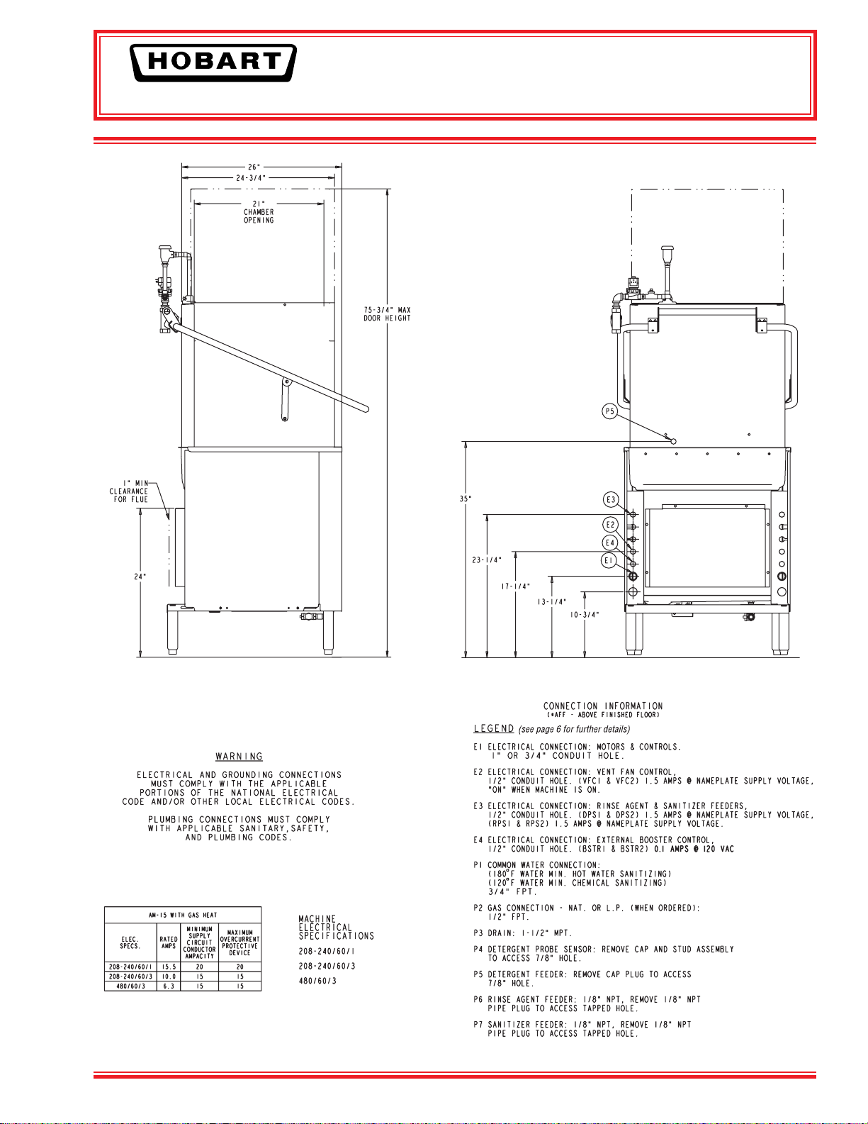
Inside Tank at Table Connection (Inches) 25
(H x W x D) (Inches) 66.5" x 27" x 28.5"
2 2
Gallons 14 14
Gallons per Minute - Weir Test 160 160
(For keeping power wash water hot)
Gas Burner (Regulated) Natural/LP Gas BTU/Hr.
Electric Heating Unit (Regulated) 5 kw 5 kw
Minutes operated during hour of capacity operation 9.66 10.83
Seconds of rinse per rack 10 10
Gallons per Minute - at 20 lbs. Flow Pressure 4.4 4.4
Gallons per Hour - at 20 lbs. Flow Pressure 42.9 48.1
Gallons per Rack - at 20 PSI Flow .74 - 180°F Min. .74 - 140°F Min.
if used based on 20 PSI steam - 20 PSI water owing
130°F entering water raised to 180°F min. (50°F rise) - Lbs. per Hour
Gallons per Minute (Initial rate with full tank) 38 38
450 450
Approx. lbs. - Unit only, with booster
58 65
1
⁄4" 251⁄4"
25,000 25,000
40 40
354 w/o Booster
384 w/Booster
354
Page 6 of 8 F-40078 – AM Select Dishwasher
Page 9
AM SELECT
AM15 Dishwasher Technical Manual Page 9 of 83
701 S Ridge Avenue, Troy, OH 45374
DISHWASHER
F-40078 – AM Select Dishwasher Page 7 of 8
Page 10

AM SELECT
AM15 Dishwasher Technical Manual Page 10 of 83
DISHWASHER
The microcomputer-based control system is built into the
AM Select dishwasher. It is available in standard electrical
specications of 208-240/60/1, 208-240/60/3, 480/60/3,
200-240/50/3, 380-415/50/3 and is equipped with a reduced
voltage pilot circuit transformer.
*CAUTION: CERTAIN MATERIALS, INCLUDING SILVER,
ALUMINUM AND PEWTER ARE ATTACKED BY SODIUM
HARDNESS MUST BE CONTROLLED TO 4-6 GRAINS FOR
CONSTRUCTION: Drawn tank, tank shelf and feet constructed
of 16 gauge stainless steel. Wash chamber and front trim panel
above motor compartment are polished, satin nish. Frame is
12 gauge stainless steel, chamber is 18 gauge, and removable
trim panels are 20 gauge.
CHAMBER LIFT: Chamber coupled by stainless steel handle,
spring counterbalanced. Chamber guided for ease of operation
and long life.
PUMP: With stainless steel pump and impeller, integral with
motor assures alignment and quiet operation. Pump shaft seal
with stainless steel parts and a carbon ceramic sealing interface.
Easily removable impeller housing permits ease of inspection.
Capacity 160 GPM. Pump is completely self-draining.
MOTOR: Built for Hobart, 2 H.P., with inherent thermal
protection, grease-packed ball bearings, splash-proof design,
ventilated. Single-phase is capacitor-start, induction-run type.
Three-phase is squirrel-cage, induction type.
MICROCOMPUTER CONTROL SYSTEM: Hobart
microcomputer controls, assembled within water-resistant
enclosure, provide built-in performance and reliability.
The microcomputer control, relays and contactors are housed
behind a stainless steel enclosure, hinged to provide easy
access for servicing. The line voltage electrical components are
completely wired with 105°C, 600V thermoplastic insulated wire
with stranded conductors and routed through listed electrical
conduit. Electrical components are wired with type ST cord.
Line disconnect switch NOT furnished.
CYCLE OPERATION: The microcomputer-timing program is
started by closing the doors, which actuates the door cycle
switch. The microcomputer energizes the wash pump motor
contactor during the wash portion of the program. After the
wash, a dwell permits the upper wash manifold to drain. At the
end of the dwell, the nal rinse solenoid valve is energized. After
the nal rinse valve closes, Sani-Dwell (Hot Water Mode only)
permits sanitization to continue. The Rinse display remains on
during this period, completing the program. If the microcomputer is interrupted during a cycle by the door-cycle switch,
the microcomputer is reset to the beginning of the program.
38
Second Wash, 2 Second Dwell, 10 Second Rinse, 7 Second
Sani-Dwell.
38 Second Wash, 2 Second Dwell, 10 Second Rinse.
Other programs can be pre-selected by your Hobart service
technician.
Manual wash cycle selector also provides selection of 2-, 4- or
6-minute wash cycles for heavier washing applications.
As continued product improvement is a policy of Hobart, specications are subject to change without notice.
701 S Ridge Avenue, Troy, OH 45374
WASH: Hobart revolving stainless steel wash arms with unrestricted openings above and below provide thorough distribution of water jets to all dishware surfaces. Arms are easily
removable for cleaning and are interchangeable. Stainless steel
tubing manifold connects upper and lower spray system.
RINSE: Rotating rinse arms, both upper and lower, feature 14
rinse nozzles. The stainless steel upper and lower rinse arms
are easily removable without tools for inspection and are
interchangeable. Diaphragm-type rinse control solenoid valve
mounted outside machine. Machine is equipped with special hot
water vacuum breaker on downstream side of rinse valve –
mounted 6" above uppermost rinse opening. Easy open brass
line strainer furnished.
FILL: Microcomputer controlled ll valve installed on upstream
side of rinse vacuum breaker. Ratio ll method is used giving
the correct ll at any owing water pressure. (20 PSIG minimum
necessary for proper rinsing.)
DRAIN AND OVERFLOW: Large bell type automatic overow
and drain valve controlled from inside of machine. Drain
automatically closed by lowering chamber. Drain seal is large
diameter, high temperature “O” ring. Cover for overow is
integral part of the standpipe.
STRAINER SYSTEM: Equipped with large, exclusive self-ushing, easily removable perforated stainless steel, one-piece
strainer and large capacity scrap basket. Submerged scrap
basket minimizes frequent removal and cleaning.
Standard tank heat is 5KW electric
_immersion heating element. Regulated power infrared gas
immersion tube system is optional at extra cost. A solid-state
igniter board controls the gas valve and provides ame ignition.
A transformer steps the control circuit voltage down to 24 volts
to power the igniter board and gas valves.
Gas Heated Dishwasher: For natural gas, gas pressure
(customer connection) not to exceed 7" W.C. For liqueed
petroleum, gas pressure to burner (customer connection) not to
exceed 11" W.C. If gas pressure is higher than 7" W.C. natural
or 11" W.C. LP, a pressure regulating valve must be supplied
(by others) in the gas line to the dishwasher. Water temperature
regulation is controlled by thermistor sensor in combination with
microcomputer controls. The tank heat and positive low water
protection microcomputer circuits are automatically activated
when the main power switch is turned “on”. If tank is accidentally drained, low water protection device automatically turns heat
off. Gas immersion tube is additionally protected by a high limit
device mounted on the surface of the tube. These features are
standard with the Hobart Microcomputer Control System.
BOOSTER HEATER: Electric booster with Sense-A-TempTM
technology adequately sized to raise 110°F inlet water to 180°F
(not available on gas heat machines).
3
ACCESSORIES: 19
Splash shield for corner installations. End of cycle audible alarm
(eld activated). Delime notication (eld activated). Desirable
functional accessories can be furnished at added cost. See
listed options and accessories on this specication sheet. Write
to the factory for special requirements not listed above.
⁄4" x 193⁄4" peg and combination dish racks.
Page 8 of 8 F-40078 – AM Select Dishwasher
F-40078 (REV. 07/09) LITHO IN U.S.A. (H-01)
Page 11

AM SELECT DISHWASHERS
AM15 Dishwasher Technical Manual Page 11 of 83
MODELS
AM15 ML-130038
AM15F ML-130045
AM15T ML-130039
701 S. RIDGE AVENUE
TROY, OHIO 45374-0001
937 332-3000
www.hobartcorp.com
FORM 35320 Rev. C (Oct. 2009)
Page 12
POST IN A PROMINENT LOCATION THE INSTRUCTIONS TO BE FOLLOWED IN THE
AM15 Dishwasher Technical Manual Page 12 of 83
EVENT THE SMELL OF GAS IS DETECTED. THIS INFORMATION CAN BE OBTAINED
FROM THE LOCAL GAS SUPPLIER.
IMPORTANT
IN THE EVENT A GAS ODOR IS DETECTED, SHUT
DOWN UNIT(S) AT MAIN SHUTOFF VALVE AND
CONTACT THE LOCAL GAS COMPANY OR GAS
SUPPLIER FOR SERVICE.
FOR YOUR SAFETY
DO NOT STORE OR USE GASOLINE OR OTHER
FLAMMABLE VA PORS OR LIQUIDS IN THE
VICINITY OF THIS OR ANY OTHER APPLIANCE.
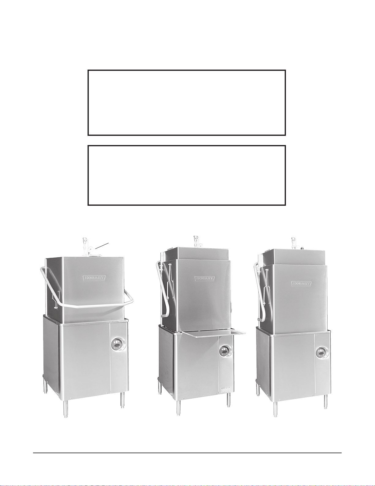
Model AM15 Model AM15F Model AM15T
PRESSURE
GAUGE
© HOBART CORPORATION, 2009
Fig. 1
– 2 –
Page 13

TABLE OF CONTENTS
AM15 Dishwasher Technical Manual Page 13 of 83
GENERAL ..................................................................4
INSTALLATION ..............................................................5
UNPACKING ..............................................................5
INSTALLATION CODES .....................................................5
LOCATION ...............................................................5
CORNER INSTALLATION ................................................6
WATER REQUIREMENTS ....................................................7
PLUMBING CONNECTIONS .................................................8
DRAIN CONNECTION ................................................... 8
WATER CONNECTION ..................................................8
Without Electric Booster Water Heater ...................................8
With Electric Booster Water Heater ......................................8
GAS TANK HEAT (When Specied) ............................................9
VENTING REQUIREMENTS — WITH GAS TANK HEAT ........................ 10
Rate of Exhaust Flow Calculations ..................................... 11
ELECTRICAL CONNECTIONS ...............................................12
Dishwasher Without Electric Booster ................................... 12
Check Rotation (Three Phase Machines Only) ............................12
Dishwasher With Electric Booster (Separately Connected) ................... 13
Dishwasher With Electric Booster (Single Point Electrical Connection) ..........13
EQUIPMENT CONNECTIONS ............................................... 13
Vent Fan Control ................................................... 13
Remote Booster Control ............................................. 13
DETERGENT, RINSE AID, SANITIZER DISPENSERS – TUBING INSTALLATION ......... 14
Detergent Dispenser ................................................ 14
Rinse Aid Dispenser .................................................14
Chemical Sanitizer Dispenser ......................................... 14
EQUIPMENT CONNECTIONS – Detergent, Rinse Aid, Sanitizer Dispensers ............ 15
Detergent Dispenser ................................................ 15
Rinse Aid / Sanitizer Dispenser(s) ......................................15
SETUP (All Models) ........................................................ 16
Sanitizing Mode ....................................................16
End of Cycle Buzzer. . . . . . . . . . . . . . . . . . . . . . . . . . . . . . . . . . . . . . . . . . . . . . . . . 16
OPERATION ............................................................... 17
PREPARATION ....................................................... 17
DISHWASHING .......................................................18
CLEANING ........................................................... 19
DELIME INSTRUCTIONS ................................................20
DOs AND DON’Ts FOR YOUR NEW HOBART WAREWASHER .................. 20
MAINTENANCE. . . . . . . . . . . . . . . . . . . . . . . . . . . . . . . . . . . . . . . . . . . . . . . . . . . . . . . . . . . . . 21
Wash Arms ........................................................21
Motor(s) ..........................................................21
Flue (Machines Equipped With Gas Tank Heat Only) ........................21
TROUBLESHOOTING ........................................................22
Manual Reset Button on Pump Motor ...................................22
SERVICE .................................................................. 24
– 3 –
Page 14

Installation, Operation, and Care of
AM15 Dishwasher Technical Manual Page 14 of 83
AM SELECT DISHWASHERS
SAVE THESE INSTRUCTIONS
GENERAL
Models AM15 and AM15T dishwashers can be congured for straight through or corner operation.
Model AM15F is congured for front loading. AM15 and AM15T dishwashers are shipped from the
factory in straight-through conguration. Straight-through machines can easily be converted to corner
operation. Model AM15F includes a front-loader shelf and left- and right-side shields as standard
equipment. The front-loader shelf on AM15F can be positioned up (inside the machine during
operation) or down (outside the machine during operation).
AM15, AM15F and AM15T dishwashers are designed to operate in one of two modes: Hot water
sanitizing mode (designated by the letters “AH” or “AP” on the display when the machine is turned on),
or a chemical sanitizing mode (designated by the letters “AC” on the display when the machine is turned
on).
The serial number can be found on the machine data plate located on the bottom of the front panel.
DO NOT attempt to operate this dishwasher in the chemical sanitizing mode without a properly
installed, NSF-certied, chemical sanitizer feeder (not supplied with machine). Contact an authorized
detergent representative for information about a chemical sanitizer feeder.
The pump motor is rated 2 H.P. and has thermal overload protection.
The ll line incorporates an atmospheric vacuum breaker to prevent any reverse ow of water from the
dishwasher into the potable water supply.
The unit, once turned on, will ll the wash tank to the appropriate level and automatically stop lling
once the level is reached.
A oat, located in the wash tank, will shut off the heat supply if the water level becomes too low. When
the water returns to a proper level, the heating circuit is again operational.
A frame-mounted 8.5 KW electric booster water heater is available as an option on machines equipped
with electric tank heat. The booster water heater is designed to maintain a minimum nal rinse
temperature of 180°F provided the incoming water to the booster heater is at least 110°F.
High-temperature or gas heat dishwashers will probably require a hood or vent over the dishwasher in
order to meet local codes. Low-temperature chemical sanitizing machines or low usage electric heat
dishwashers may not require individual venting of the machine if the room is amply exhausted. Refer
to pages 10 and 11 for venting and hood requirements. Verify with local codes for nal authority.
– 4 –
Page 15
INSTALLATION
AM15 Dishwasher Technical Manual Page 15 of 83
UNPACKING
Immediately after unpacking the dishwasher, check for possible shipping damage. If this machine is
found to be damaged, save the packaging material and contact the carrier within 15 days of delivery.
Prior to installation, test the electrical service to make sure it agrees with the specications on the
machine data plate; this includes the optional electric booster, if equipped. The dishwasher data plate
is located at the bottom of the front panel.
INSTALLATION CODES
Installation must be in accordance with state and local codes, or in the absence of local codes, with
the National Fuel Gas Code, ANSI Z223.1 (latest edition) if applicable, and the National Electrical Code
ANSI/NFPA 70 (latest edition). In Canada, the installation standards are: CAN/CGA B149.1,
CAN/CGA B149.2, and CSA C22.2 No.1 (latest editions).
LO CATION
Before nalizing the location, make sure that consideration has been given for the electrical conduit,
water supply, drain connection, gas supply and venting (if applicable), tabling (if needed), chemical
feeder replenishment (if applicable) and adequate clearance for opening the door.
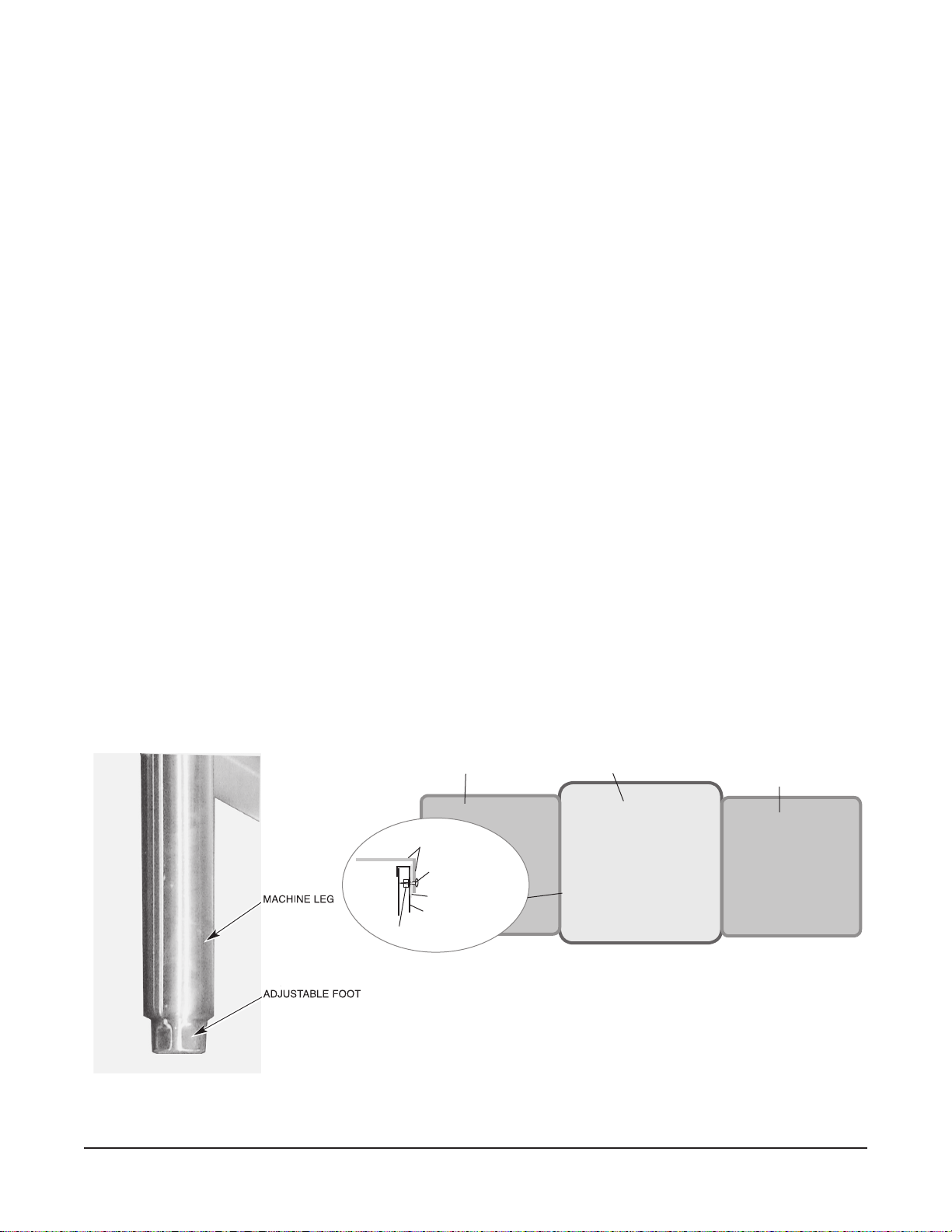
The dishwasher must be level before any connections are made. Turn the threaded feet (Fig. 2) as
required to level the machine and adjust to the desired height.
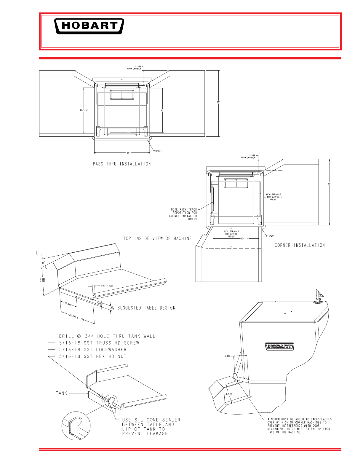
The edge of dish table that overhangs the AM15 wash tank should be turned down and tted over the
top of the dishwasher tank (Fig. 3). Apply an NSF approved sealant between the overhang of the dish
table and the inner wall of the wash tank to prevent leakage (Fig. 3). Fasten the dish tables to the inner
wall of the wash tank with non-rusting truss head screws or rivets (Fig. 3).
For straight-through installations, clearance at the front and 15 inches out from the dishwasher at the
right side by 27 inches above the nished oor must be provided for servicing.
WASH TANK
DISH TABLE
Fig. 3
DISH TABLE
MACHINE SC REW
OR RIVE T
SEALANT
INNER WA LL OF
WASH TANK
NUT
DISH TABLE
STRAIGHT-THROUGH OPERATION SHOWN
Fig. 2
– 5 –
Page 16

CORNER INSTALLATION
AM15 Dishwasher Technical Manual Page 16 of 83
Before placing the dishwasher in its operating location, check machine conguration. If the machine
is being installed in a corner (Figs. 4, 5), clearances of 20 inches out from the dishwasher under the
left-hand tabling by 27 inches above the nished oor and 15 inches out from the dishwasher at the
right side by 27 inches above the nished oor must be provided for servicing. For proper installation
of a corner machine, the control and display should be positioned at the front corner for operator access
(Fig. 5).
For corner installation, rotate the rack track so the guide rail is positioned on the left side (Fig. 6). For
corner machines, remove the front door deector (unscrew three bolts / nuts, Fig. 7).
WASH TANK
CORNER OPERATION SHOWN
DISH TABLE
DISH TABLE
MACHINE SC REW
OR RIVE T
SEALANT
INNER WA LL OF
WASH TANK
NUT
CONTROLS MUST BE ACCESSIBLE AT
FRONT CORNER.
DISH TABLE
Fig. 4 Fig. 5
Fig. 6 Fig. 7
– 6 –
Page 17
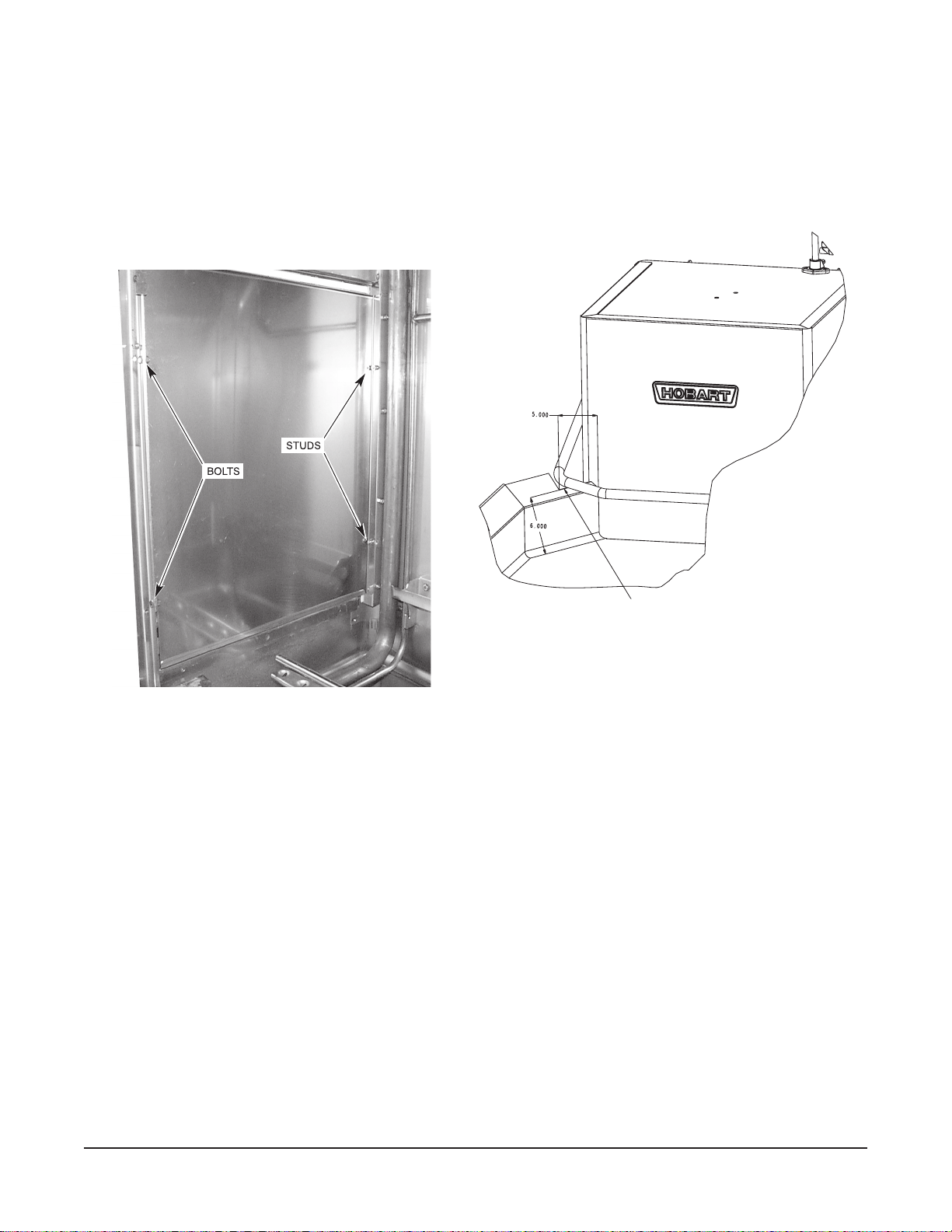
A splash shield is available (at extra cost) for corner installations to cover the left side opening to the
AM15 Dishwasher Technical Manual Page 17 of 83
1
wall. Install the splash shield on the left side using the two
lockwasher and nut for each (Fig. 8) and using the two
⁄4-20 studs on the left rear corner with a
1
⁄4-20 bolts, lockwashers and nuts on the left
front corner (fasteners are provided in the kit).
For corner installations, tabling with backsplashes over 6" high require that a notch be provided to
prevent interference with the door mechanism (Fig. 9).
A NOTCH MUST BE ADDED TO BACKSPLASHES
OVER 6" HIGH ON CORNER MACHINES TO
PREVENT INTERFERENCE WITH DOOR
MECHANISM. NOTCH MUST EXTEND 5" FROM
FACE OF THE MACHINE.
Fig. 8 Fig. 9
WATER REQUIREMENTS
Proper water quality can improve warewashing performance by reducing spotting, lowering chemical
supply costs, improving productivity and extending equipment life. Local water conditions vary from
one location to another. The recommended proper water treatment for effective and efcient use of
this equipment will also vary depending on the local water conditions. Ask your municipal water
supplier for details about local water specics prior to installation.
Recommended water hardness is 3 grains of hardness per gallon or less. Chlorides must not exceed
50 parts per million. Water hardness above 3 grains per gallon should be treated by a water conditioner
(water softener or in-line treatment). Water treatment has been shown to reduce costs associated with
machine cleaning, reduce the need for deliming the dishwasher and reduce detergent usage.
Sediment, silica, chlorides or other dissolved solids may lead to a recommendation for particulate
ltration or reverse osmosis treatment.
If an inspection of the dishwasher or booster heater reveals lime build-up after the equipment has been
in service, in-line water treatment should be considered, and, if recommended, should be installed and
used as directed. Contact your Hobart Service ofce for specic recommendations.
– 7 –
Page 18

PLUMBING CONNECTIONS
AM15 Dishwasher Technical Manual Page 18 of 83
WARNING:
PLUMBING CONNECTIONS MUST COMPLY WITH APPLICABLE SANITARY, SAFETY AND
PLUMBING CODES.
DRAIN CONNECTION
The drain connection is a 1
1
⁄2 " externally threaded pipe connected
straight down from the bottom of the wash tank (Fig. 10). The
connection can be made in any direction by using the proper tting
(not supplied) and routing to the appropriate drain line.
If a grease trap is required by code, it should have a minimum ow
capacity of 38 gallons per minute.
Fig. 10
WATER CONNECTION
A suitable water hammer arrestor should be installed in the water line just ahead of the dishwasher.
Without Electric Booster Water Heater
3
The water supply line is connected to the line strainer (top rear, Fig. 1) with
⁄4" pipe. A manual shutoff
valve and pipe union are required (not supplied).
REQUIRED INCOMING WATER TEMPERATURE
Model Sanitizing Mode
Without Built-in Booster Hot Water Sanitizing 180°F
Without Built-in Booster Chemical Sanitizing 120°F (49°C) 140°F (60°C)
With Built-in Booster Hot Water Sanitizing 110°F (43°C) 140°F (60°C)
Minimum Temperature Recommended Temperature
(82°C) 180°F (82°C)
Water Supply
Proper dishwasher operation requires a owing pressure of 20 ± 5 psig at the dishwasher. If the owing
pressure exceeds 25 psig, a pressure reducing valve (not supplied) must be installed in the water
supply line. CAUTION: The water pressure regulator must have a relief by-pass. Failure to use
the proper type of pressure regulator may result in damage to the unit.
A pressure gauge (Fig. 1) is provided (not installed) for verication of proper water pressure. The water
pressure is monitored when the solenoid valve is open and water is owing.
With Electric Booster Water Heater
The water supply line is connected below the booster with the line strainer (supplied) and
3
⁄4" pipe. A
manual shut off valve and pipe union are required (not supplied).
The water supply should have a minimum temperature of 110°F, and a owing pressure of 20 ± 5 psig
at the pressure gauge on top of the machine. If the owing pressure exceeds 25 psig, a pressure
reducing valve (not supplied) must be installed in the water supply line. CAUTION: The water
pressure regulator must have a relief by-pass. Failure to use the proper type of pressure
regulator may result in damage to the unit.
Incoming water temperature below 110°F may require longer wash cycle time than the 57 second cycle;
refer to OPERATION, pages 17 – 18.
When the ll / nal rinse valve is on, water from the booster tank enters the dishwasher through the nal
rinse arms. During the rinse cycle, this water is 180°F. A small amount of water will likely dribble out
of the lower rinse arm into the tank between cycles due to the natural expansion of water as it is being
heated.
– 8 –
Page 19
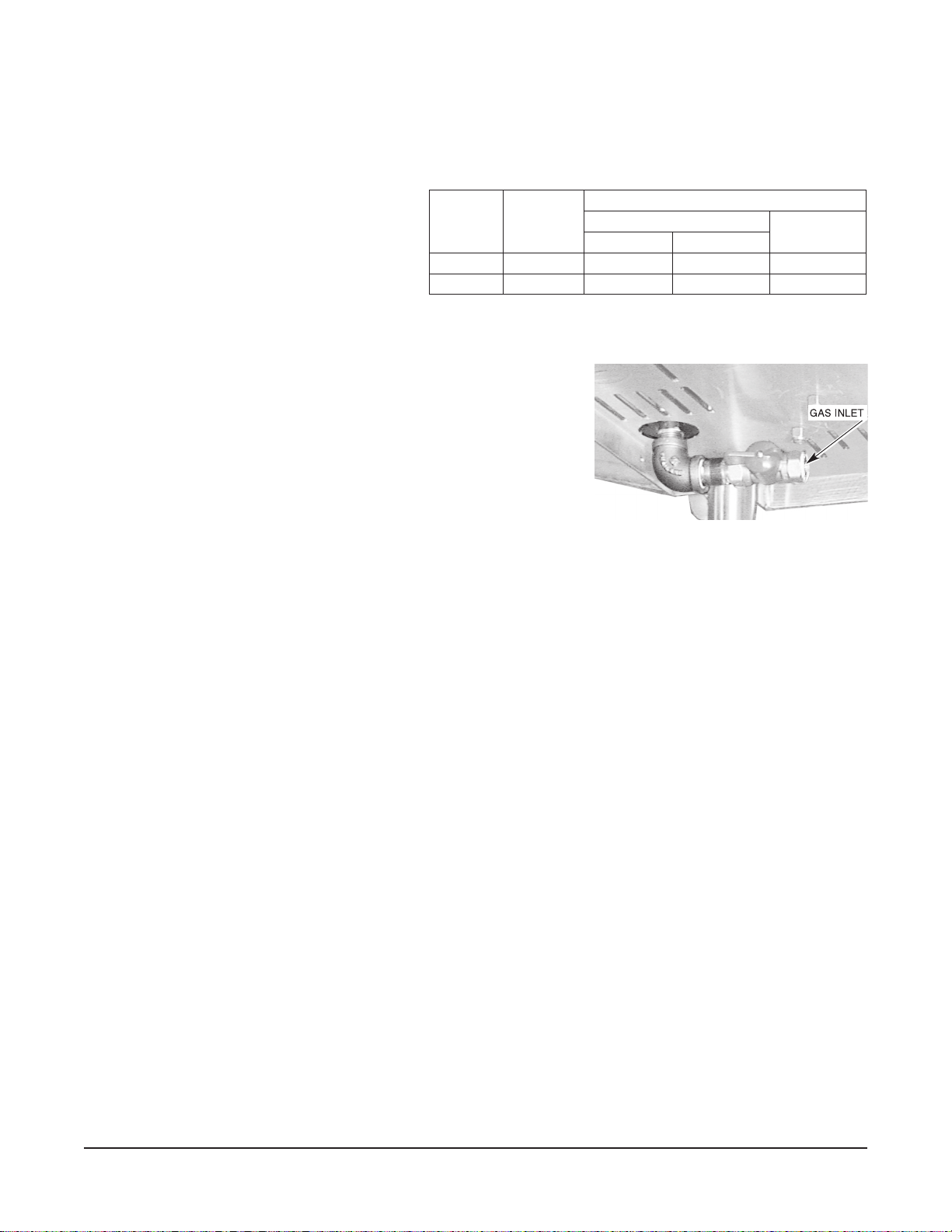
GAS TANK HEAT (When Specified)
AM15 Dishwasher Technical Manual Page 19 of 83
Check the gas data plate attached to the dishwasher or the tag attached to the incoming gas piping
for the type of gas to be used.
GAS PRESSURE SPECIFICATION
The burner is not adjustable. The maximum
owing inlet gas pressure must not exceed
the Maximum value in the table. If line
pressure exceeds the Maximum value in
the table, an additional pressure regulator
(not supplied) must be installed in the
[FLOWING GAS PRESSURE — NOT STATIC]
Type
of
Gas
Natural 25,000 3.5 7. 0 3.2
Propane 25,000 9.0 11.0 8.2
BTU/HR
Inches W.C. (Water Column) FLOWING
Incoming Line Pressure
Minimum Maximum
Manifold
Pressure
supply line.
Static inlet line pressure should not exceed 14" W.C. The minimum value is for input adjustment.
The gas valve is provided with a pressure tap to measure the gas
pressure downstream, which is also the manifold pressure. Gas
supply piping must have a sediment trap (supplied by others)
installed ahead of the dishwasher’s gas control. Connect the gas
1
supply to the
⁄2" NPT gas inlet underneath the machine (Fig. 11).
NOTE: DO NOT use Teon tape on gas line pipe threads. For
gas line pipe connections, use L
o c t i t e 565, Hobart part 546292,
or a exible sealant suitable for use with Natural and Propane
Gases.
Fig. 11
The appliance and its gas connections must be leak tested before placing the appliance in operation.
Use soapy water for leak test. DO N OT use open ame. The installation must conform with local codes,
or in the absence of local codes, with the National Fuel Gas Code, ANSI Z223.1 (latest edition). Copies
may be obtained from American Gas Association, Inc., 1515 Wilson Boulevard, Arlington, VA 22209.
The appliance and its individual shutoff valve must be disconnected from the gas supply piping system
1
during any pressure testing of that system at test pressures in excess of
⁄2 psig (3.45kPa).
The appliance must be isolated from the gas supply piping system by closing its individual manual
shutoff valve during any pressure testing of the gas supply piping system at test pressures equal to or
1
less than
⁄2 psig (3.45kPa).
Dissipate test pressure from the gas supply line before re-connecting the appliance and its manual
shutoff valve to the gas supply line. Caution: Failure to follow this procedure may damage the gas
valve.
The dishwasher must be installed so that the ow of combustion and ventilation air will not be
obstructed. Do not store material underneath the machine; air openings into the combustion chamber
must not be blocked. Make sure there is an adequate supply of make-up air in the room to allow for
combustion of the gas at the burner.
Keep the appliance area free and clear from all combustible substances. Do not obstruct the ow of
combustion and ventilation air. The dishwasher must have a minimum clearance from combustible
construction of 1 inch from the ue at the rear. Clearances of 20 inches out from the dishwasher at
the front (or left side in a corner installation) by 27 inches above the nished oor and 15 inches out
from the dishwasher at the right side by 27 inches above the nished oor must be provided for
servicing.
The burner is ignited automatically by solid state electronic circuitry; there is no pilot light. Gas ow
is regulated by the temperature control circuit.
– 9 –
Page 20
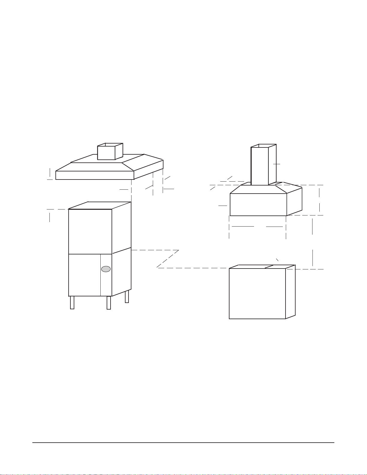
VENTING REQUIREMENTS — WITH GAS TANK HEAT
AM15 Dishwasher Technical Manual Page 20 of 83
Hobart model AM15, AM15F or AM15T dishwashers equipped for gas tank heat are not provided with
a ue collar and are not intended to have the ue directly connected to a ventilation system. However,
the products of combustion must be vented to the outside air. The most common method of venting
is a vent hood over the entire dishwasher (Fig. 12). Refer to Rate of Exhaust Flow Calculations on the
next page for calculations of the proper vent rate for your hood. Another method is a small vent hood
(Fig. 13) positioned about ve inches above the ue exit at the rear of the dishwasher and connected
to existing ductwork. In either case, an electrical interlock must be installed to allow the ow of gas
to the dishwasher burner ONLY when the exhaust system is energized. For additional information,
refer to the National Fuel Gas Code, ANSI Z223.1, NFPA 54.
•IMPORTANT: Make sure the installation meets the local code for your area.
3" x 3" DUCT INTO
➤
CURRENT SYSTEM
➤
1' TO 4'
CLEARANCE
➤
➤
6"
MINIMUM
OVERHANG
ON ALL SIDES
➤
➤
➤
MINI VENT HOOD
18" OVERHANG
RECOMMENDED
OVER LOADING OR
UNLOADING DOORS
31⁄2"
➤
➤
➤
➤
6"
➤
MINIMUM
➤
4"
➤
➤
5" GAP
DISHWASHER FLUE EXIT
Fig. 12 Fig. 13
➤
➤
– 10 –
Page 21
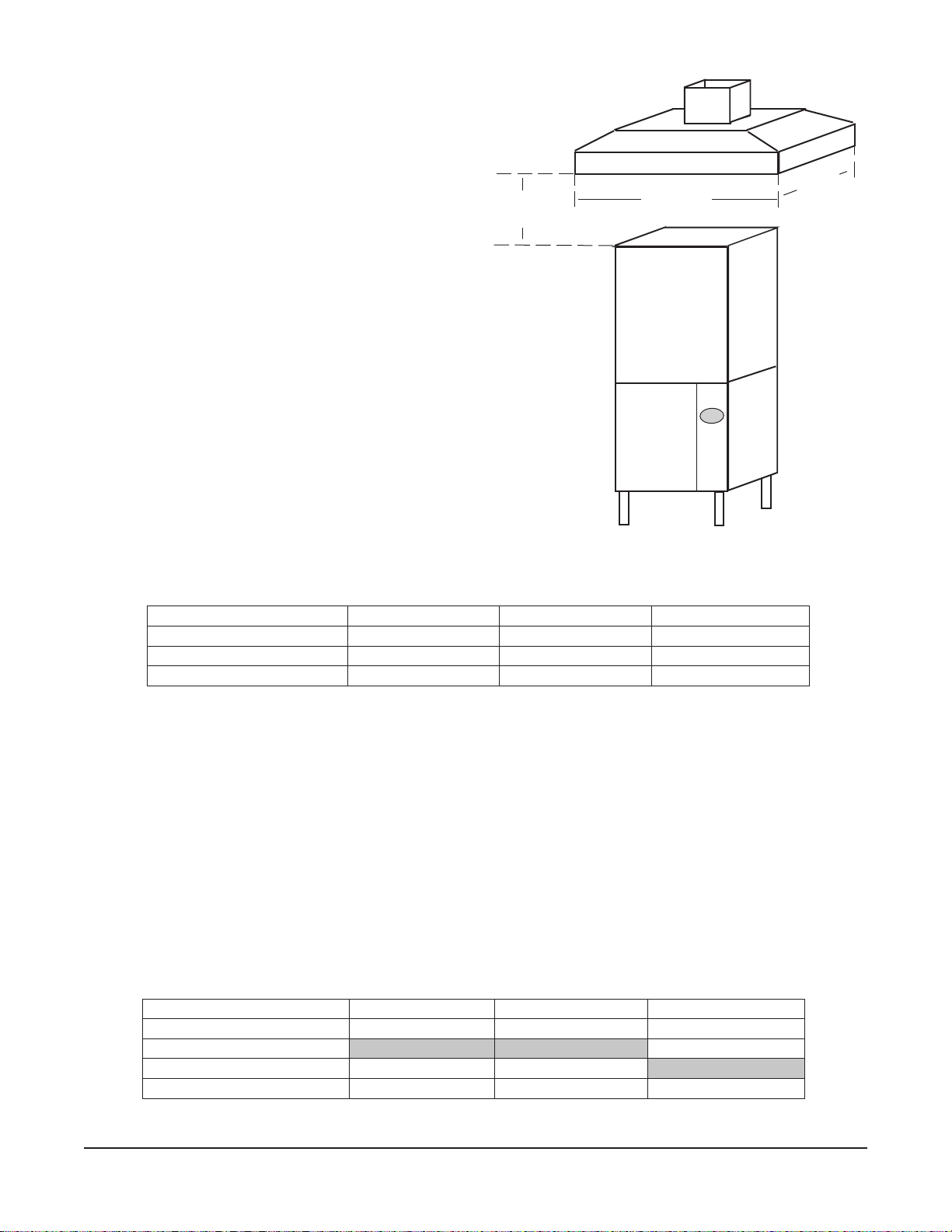
NOTE: Any listed and labeled factory-built
AM15 Dishwasher Technical Manual Page 21 of 83
commercial exhaust hood tested in accordance
with UL Standard 710 by a nationally recognized
testing laboratory, should be installed according
to the terms of its listing and the manufacturer’s
installation instructions.
RATE OF EXHAUST FLOW CALCULATIONS
Based on the 1996 International Mechanical Code.
The Rate of air ow required for a vent hood is
calculated using the following denitions (Fig. 14):
Q = Rate of Air Flow in Cubic Feet Per Minute
or [ CFM ] Required for the Hood.
2
A = Area of Hood Opening in Feet
= (L x W)
D = Clearance Height = Distance in Feet from
lower lip of hood to top of dishwasher
chamber.
P = Perimeter of Hood that is Open. This
depends on the hood design, as follows:
➤
CLEARANCE
HEIGHT
➤
➤
WIDTH
➤
➤
LENGTH
Fig. 14
➤
Perimeter Calculation Formula
Hood Design
Number of Open Sides
P =
Dimensions
Corner Wall Island
2 Sides Open 3 Sides Open 4 Sides Open
L + W L + W + W L + L + W + W
Feet Feet Feet
If there are four open sides (Island Design), the calculation of the Rate is as follows:
Q = 75 x A
If there are three or fewer open sides, the calculation of the Rate is as follows:
Q = 50 x A
As an alternate method, the Rate can be calculated as follows:
Q = 50 x P x D
Example:
L = 3 W = 3 D = 2
Rate Calculations
Hood Design
Number of Open Sides
Q = 75 x A
Q = 50 x A
Q = 50 x P x D
Corner Wall Island
2 Sides Open 3 Sides Open 4 Sides Open
675 CFM
450 CFM 450 CFM
600 CFM 900 CFM 1200 CFM
– 11 –
Page 22

ELECTRICAL CONNECTIONS
AM15 Dishwasher Technical Manual Page 22 of 83
WARNING: ELECTRICAL AND GROUNDING CONNECTIONS MUST COMPLY WITH THE APPLICABLE
PORTIONS OF THE NATIONAL ELECTRICAL CODE AND/OR OTHER LOCAL ELECTRICAL CODES.
WARNING: DISCONNECT THE ELECTRICAL POWER TO THE MACHINE (BOTH DISHWASHER AND
BOOSTER IF APPLICABLE) AND FOLLOW LOCKOUT / TAGOUT PROCEDURES.
Refer to the wiring diagram attached inside the front trim panel and to the machine data plate for service
size requirements when connecting the dishwasher. Also, refer to Electrical Data, page 12.
To access the controls area, remove the right side panel, remove the front panel and open the control
3
panel door. The dishwasher electrical service connection can be made through the 1
3
⁄4 inch trade size conduit located on the right side at the rear of the machine. By removing a
for
knockout, this hole can be enlarged to 1
3
⁄8" diameter for 1 inch trade size conduit, if required.
⁄32" diameter hole
ELECTRICAL DATA
Minimum Circuit Ampacity
Maximum Protective Device
AMPS
Models Volts / Hz / Ph Tank Heat
Dishwasher
ONLY
208 - 240 / 60 / 1
AM15
AM15F
AM15T
Compiled in accordance with the national electrical code, NFPA 70 (latest edition).
208 - 240 / 60 / 3
480 / 60 / 3
200 - 240 / 50 / 3 Electric 30 30 60
380 - 415 / 50 / 3 Electric 15 15 30
Electric 50 50
Gas 20
Electric 30 30 60
Gas 15
Electric 15 15 30
Gas 15
Optional 8.5 KW Electric Booster
8.5 KW
Booster
ONLY
Optional Single Point
Electrical Connection
3 Phase Only
Dishwasher and Booster
A fused disconnect switch or circuit breaker (not supplied) must be installed in the electrical service
line(s) supplying this dishwasher and should meet the requirements of your local electrical code.
Dishwasher Without Electric Booster
For single-phase machines, power supply connections are made to terminal blocks. For three-phase
machines connections are made to contactor lugs. The machine must be grounded according to
electrical code(s); a grounding lug is provided in the controls area. Electrical connections for machines
with gas tank heat are made to contactor 1CON in the controls area.
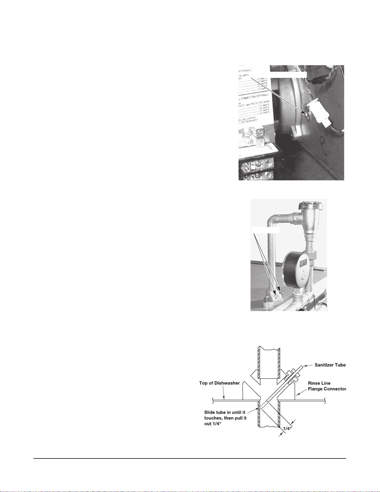
Check Rotation (Three-Phase Machines Only)
Three-phase motors must rotate in the direction of the arrow on
the pump housing. In order to check rotation, remove the bearing
cap to observe the motor shaft (Fig. 15). Close the machine doors
and press the power switch to ON. When the machine is completely
lled, open and close machine doors to verify that the motor shaft
rotates in the clockwise direction.
If the rotation is incorrect, DISCONNECT ELECTRICAL POWER
SUPPLY and interchange any two of the incoming power supply
leads. Reconnect the power supply and verify correct rotation.
Replace the motor bearing cap.
– 12 –
Fig. 15
Page 23
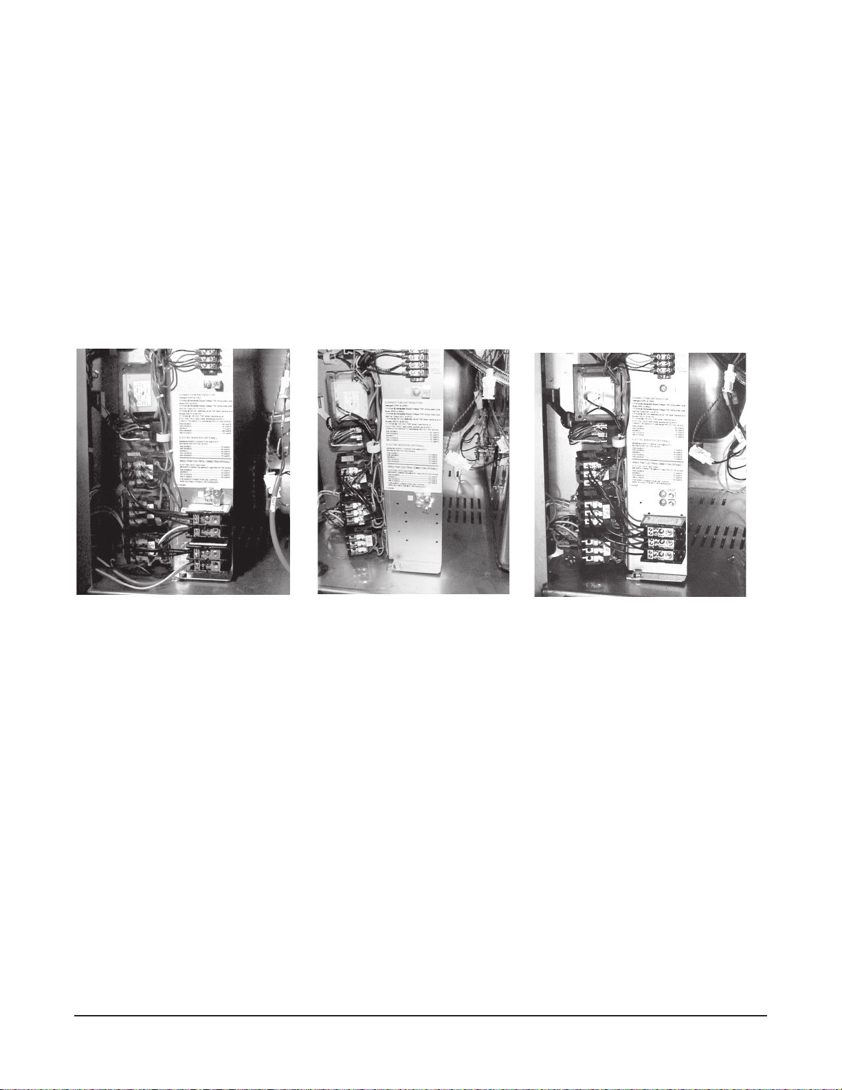
Dishwasher With Electric Booster (Separately Connected)
AM15 Dishwasher Technical Manual Page 23 of 83
Single phase machines with an electric booster require two separate connections, one for the booster
and the other for the dishwasher (including motor, controls and tank heat). For single-phase machines,
all power supply connections are made to terminal blocks (Fig. 16). The single phase dishwasher is
connected to terminal block 1TB in the controls area. The single phase booster is connected to
terminal block 2TB in the controls area.
If the machine is three phase, the electrical connection for the dishwasher is made to the contactor
2CON in the controls area. The electrical connection for the three phase booster is made to the
contactor 3CON in the controls area (Fig. 17).
Dishwasher With Electric Booster (Single Point Electrical Connection)
Three phase machines congured with the optional single point electrical connection are connected
to terminal block 1TB in the controls area (Fig. 18). The machine must be grounded according to
electrical code(s); a grounding lug is provided.
Fig. 16 Fig. 17 Fig. 18
EQUIPMENT CONNECTIONS
WARNING: ELECTRICAL AND GROUNDING CONNECTIONS MUST COMPLY WITH THE APPLICABLE
PORTIONS OF THE NATIONAL ELECTRICAL CODE AND/OR OTHER LOCAL ELECTRICAL CODES.
WARNING: DISCONNECT THE ELECTRICAL POWER TO THE MACHINE (BOTH DISHWASHER AND
BOOSTER IF APPLICABLE) AND FOLLOW LOCKOUT / TAGOUT PROCEDURES.
Vent Fan Control
The vent fan control feature is standard on all machines. The vent fan control relay provides switch
contacts only and does not provide power to the vent fan motor. The rating for a vent fan control relay
connected to terminals VFC1 and VFC2 is 1.5 Amps at 240 Volts maximum. When the dishwasher is
connected to the vent fan, the vent fan is switched on when the dishwasher is on, and off when the
dishwasher is off.
Remote Booster Control
The booster control feature is standard on all machines. The load rating for remote booster control
connections to BSTR1 and BSTR2 is 0.1 Amp. at 120 Volts maximum. The booster control provides
a control signal only and does not provide power to the remote booster. When a remote booster
is connected to the dishwasher, the booster is on when the dishwasher is on and off when the
dishwasher is off.
– 13 –
Page 24
DETERGENT, RINSE AID, SANITIZER DISPENSERS — TUBING INSTALLATION
DETERGENT SENSOR PORT
PIPE PLUGS
AM15 Dishwasher Technical Manual Page 24 of 83
Detergent, rinse aid and / or sanitizer dispensers (not provided by Hobart) must have all connections
sealed against leakage.
The dishwasher uses 0.74 gallons of rinse water per rack at a
ow rate of 4.4 gallons per minute at 20 psig owing pressure
(equivalent to a maximum head pressure of 46 feet of water).
This information is used when setting the detergent, rinse aid
or sanitizer pumps.
Detergent Dispenser
7
The dishwasher has two
⁄8" diameter plugged holes, one on
the rear of the chamber and one on the lower part of the tank
near the pump (Fig. 19). With the tank empty, remove both
plugs to install the detergent dispenser.
• Thechamberholeisforinstallationofthedetergentfeeder
tube.
• Thelowertankholeisusedforinstallationofthedetergent
Fig. 19
sensor.
Rinse Aid Dispenser
The rinse line ange connector on top of the dishwasher has two
1
⁄8" NPT pipe plugs (Fig. 20).
• Remove the plug(s) (Fig. 20) for installation of the rinse aid
dispenser tube and / or chemical sanitizer tube, as needed.
Chemical Sanitizer Dispenser
When the dishwasher is to be operated in the chemical sanitizing
mode, the machine must be converted to low-temperature
sanitization (refer to Setup, page 16). A chemical sanitizer
dispenser that has been tested and certied by NSF International
must be installed.
• Remove the pipe plug (Fig. 20) for installation
of the chemical sanitizer tube. To assure an
unobstructed flow of sanitizer, locate the
sanitizer tube in the center of water ow by
drilling the sanitizer tube tting so that its inside
diameter is equal to the outside diameter of the
tube. Slide the tube into the ange until it
touches the opposite side and then pull it back
1
⁄4 inch (Fig. 21).
out
Fig. 20
• Rate for 6% Sodium hypochlorite (bleach) —
3 ml. within 10 seconds (maximum).
• Ratefor8.4%Sodiumhypochlorite(bleach)—
2 ml. within 10 seconds (maximum).
Fig. 21
– 14 –
Page 25
EQUIPMENT CONNECTIONS — Detergent, Rinse Aid, Sanitizer Dispensers
AM15 Dishwasher Technical Manual Page 25 of 83
WARNING: ELECTRICAL AND GROUNDING CONNECTIONS MUST COMPLY WITH THE APPLICABLE
PORTIONS OF THE NATIONAL ELECTRICAL CODE AND/OR OTHER LOCAL ELECTRICAL CODES.
WARNING: DISCONNECT THE ELECTRICAL POWER TO THE MACHINE (BOTH DISHWASHER AND
BOOSTER IF APPLICABLE) AND FOLLOW LOCKOUT / TAGOUT PROCEDURES.
This machine must be operated with an automatic detergent feeder and, if applicable, an automatic
chemical sanitizer feeder, including a visual means to verify that detergents and sanitizers are
delivered or a visual or audible alarm to signal if detergents and sanitizers are not available for delivery
to the respective washing and sanitizing systems. Refer to the installation section of this manual and
to the chemical feeder equipment manual(s).
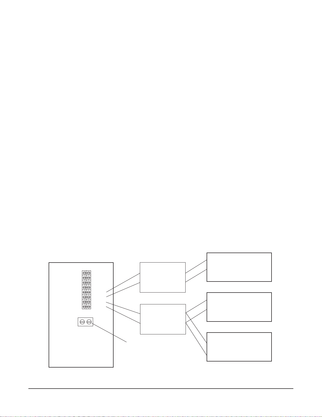
Detergent Dispenser (Fig. 22)
Terminals DPS1 and DPS2 are supplied with controlled machine line voltage. They are ON during the
wash cycle and OFF between cycles or when the machine power supply is OFF. Maximum rating for
detergent dispenser connected to DPS1 and DPS2 is 1.5 Amps at line voltage. Check the machine
supply voltage and use corresponding feeder transformer voltage. Use UL listed 600 volt minimum
insulated wire for the connections. Do not use bell wire, lamp cord or similar type wire. Splice
connections, if required, must be made in the feeder transformer junction box — not in the main
7
controls enclosure. Remove
⁄8" diameter cap plug(s) for 1⁄2" trade size conduit ttings from the rear
of the enclosure. Remove the side panel. Strain relief ttings must be provided for all wiring.
Rinse Aid / Sanitizer Dispenser(s) (Fig. 22)
Terminals RPS1 and RPS2 are supplied with controlled machine line voltage and are ON during the
rinse cycle only. Maximum rating for rinse aid dispenser connected to RPS1 and RPS2 is 1.5 Amps
at line voltage. Check the machine supply voltage and use corresponding feeder transformer voltage.
Use UL listed 600 volt minimum insulated wire for the connections. Do not use bell wire, lamp cord
or similar type wire. Splice connections, if required, must be made in the feeder transformer junction
7
box (supplied by others) — not in the main controls enslosure. Remove
1
⁄2" trade size conduit ttings from the rear of the enclosure. Strain relief ttings must be provided for
⁄8" diameter cap plug(s) for
all wiring.
DETERGENT
DISPENSER
RINSE AGENT
DISPENSER
CHEMICAL
SANITIZER
DISPENSER
— VFC1
— VFC2
— BSTR1
— BSTR2
— DPS1
— DPS2
— RPS1
— RPS2
RIGHT SIDE OF
CONTROL AREA
TRANSFORMER
PRIMARY
TRANSFORMER
PRIMARY
GROUND LUG
SECONDARY
SECONDARY
Fig. 22
– 15 –
Page 26

SETUP (All Models)
AM15 Dishwasher Technical Manual Page 26 of 83
Sanitizing Mode
• WiththemachineOFF,presstheONkey.
• ImmediatelypressandholdtheOFFkey.
The display initializes until 88 displays.
Next, SET X
°F
displays. X can be H, C or P:
°C
H = Hot Water Sanitizing, Internal Booster.
C = Chemical Sanitizing, No Booster.
P = Hot Water Sanitizing, External Booster.
• PressCYCLEtoselectP,H,orCasthesanitizingmode.
After 5 seconds, the selection is saved and the machine turns off.
End of Cycle Buzzer
• WiththemachineOFF,presstheONkey.
• ImmediatelypressandholdtheOFFkey.
The display initializes until 88 displays.
°F
Next, SET X
displays. X can be P, H or C. (See above).
°C
SET H
SET C
SET P
SHORTCUT IF
PROGR AMMING BOTH FEATURES
AT THE SAME TIME.
°F
°C
°F
°C
°F
°C
• PressandholdtheOFFkey.
Next, SET WASH XX displays. XX can be On or OF:
SET WASH On = End of Cycle Buzzer is ON.
SET WASH OF = End of Cycle Buzzer is OFF.
• PressCYCLEtoselectOnorOFfortheEndofCycleBuzzer.
After 5 seconds, the selection is saved and the machine turns off.
SET WASH On
SET WASH OF
– 16 –
Page 27

OPERATION
AM15 Dishwasher Technical Manual Page 27 of 83
PREPARATION
The overow tube must be in its proper location below the strainer pan (Fig. 23). Place the strainer
pan and the strainer bucket in their proper positions (Fig. 24).
Fig. 24
Fig. 23
An automatic detergent dispenser is recommended. Closely
follow supplier’s instructions.
Close the door; this will automatically close the drain.
Open the manual gas valve (if applicable). Press the ON
button to turn the power on (Fig. 25). If the machine’s door is
closed and no water is in the tank, the ll cycle will begin
automatically. During the ll cycle, the word FILL is displayed.
When the ll cycle has completed, the readout will display the
wash temperature. During the rinse cycle, the rinse icon and
temperature will be displayed. Select the wash cycle: 1 for
normal serving ware, 2, 4 or 6 for pots and pans. Each wash
cycle is followed by an automatic rinse. When the rinse cycle
is complete, the door can be opened.
Fig. 25
– 17 –
Page 28

DISHWASHING
AM15 Dishwasher Technical Manual Page 28 of 83
Scrape the dishes to remove large particles of food and debris. Never use steel wool on ware to be
loaded into the dishmachine.
Fig. 26
Arrange the dishes in a rack. Do not stack dishes one on top of another, as water must have free access
to all sides of every dish. Stand plates and dishes up edgewise in a peg-type rack (Fig. 26). Cups,
glasses, and bowls should be inverted in an open-type or compartment type rack (Fig. 26). Silverware
and other small pieces may be scattered loosely over the bottom of a at bottom rack.
DO NOT allow foreign objects to enter the unit, especially metallic contaminants.
After lling a rack, open the door, slide the rack into the dishwasher and close the door.
Throughout the wash cycle, the tank water temperature will be displayed on the front panel display,
along with the word WASH and an icon. During the rinse cycle, the rinse water temperature will be
displayed, along with the word RINSE and an icon. When the rinse cycle is completed, the readout will
display the tank water temperature.
When the cycle is nished and the rinse icon disappears, open the door, remove the clean dishes, slide
in another rack and close the door.
To add a dish after the wash cycle has started, open the door slightly. Wait 10 seconds to allow the
wash arm to coast down and to avoid water splashing before opening the door fully.
Operating temperatures for all models are as follows:
Sanitizing Mode
Hot Water
Chemical
Minimum Wash Recommended Wash Minimum Rinse Recommended Rinse
150°F (66°C) 150°F (66°C) 180°F (82°C) 180°F (82°C)
120°F (49°C) 14 0° F (60°C) 120°F (49°C) 140 °F (60°C)
Wash Temperature Rinse Temperature
Model AM15F has a front loader door and loading tray. The machine can operate with the loader tray
positioned vertical inside the chamber (up position) or positioned horizontal outside the chamber (down
position).
– 18 –
Page 29

CLEANING
AM15 Dishwasher Technical Manual Page 29 of 83
The machine must be thoroughly cleaned at the end of each working shift or at least daily. Never use steel
wool to clean warewasher surfaces. Use only products formulated to be safe on stainless steel.
1. Push the OFF button.
2. Open the machine door.
3. Clean off the dish tables into the dishwasher.
4. Drain the machine by lifting up the drain lever (Fig. 27).
5. Thoroughly cleanse and flush the dishwasher interior.
Remove remaining soil with a soft cloth or brush and mild
cleanser. Rinse again. Do not allow food soil to accumulate
on the tank bottom.
6. Remove and empty the strainer pan and the strainer bucket.
Wash and rinse them thoroughly.
Fig. 27
7. Clean the pump cover with a soft cloth or brush. Do not allow food soil to accumulate on the tank
bottom or to enter the drain.
8. Remove the overow tube. Wash and rinse the overow tube inside and out.
9. Make sure that the wash and rinse arms rotate freely and are free of any obstructions. If not,
remove arms and clear out any obstructions.
10. Remove and check wash arms and rinse nozzles (Figs. 28, 29) to make sure they are free of any
lime and solids. Refer to Maintenance, page 21.
NOTE: Do not bang wash arms or rinse arms to clean.
11. Replace all removed parts. Leave the machine door open to allow the interior to air out and dry.
Fig. 28 Fig. 29
– 19 –
Page 30

DELIME INSTRUCTIONS
AM15 Dishwasher Technical Manual Page 30 of 83
if the optional delime notication is activated and the DELIME light is on, follow the instructions, below.
Delime is also necessary if deposits are visible inside or outside the machine.
DELIME INSTRUCTIONS
1. Remove rack, drain tank, press “OFF”.
2. Press and hold “CYCLE” & “ON” for 3 seconds;
close door, unit fills then indicates “ADD DELIME”.
3. Open door & add delime agent per supplier
instructions for 14 gallon tank.
4. Close door, pump starts & display flashes “DELIME”.
After 12 minutes display scrolls “DRAIN”.
5. Check interior, close door to run additional cycles
if necessary.
6. Drain tank, turn unit off.
DOs AND DON’Ts FOR YOUR NEW HOBART WAREWASHER
DO assure proper water hardness (3 grains or less per gallon is recommended).
DO pre-scrap dishes thoroughly.
DO use only detergents recommended by your chemical professional.
DO at the end of the day, thoroughly cleanse the machine, rinse and dry (leave door open).
DO closely follow your chemical professional’s prescribed deliming schedule.
DO use only products formulated to be safe on stainless steel.
DO NOT use detergents formulated for residential dishwashers.
DO NOT allow food soil to accumulate on the tank bottom.
DO NOT exceed chemical manufacturer’s recommended concentrations for detergent, sanitizer, rinse
aid or lime scale remover.
DO NOT use steel wool to clean ware or warewasher surfaces.
DO NOT allow foreign objects to enter the unit, especially metallic contaminants such as paper clips,
retainers, etc.
NOTE: Failure to follow use, care and maintenance instructions may void your Hobart warewasher
warranty.
– 20 –
Page 31

MAINTENANCE
AM15 Dishwasher Technical Manual Page 31 of 83
WARNING: DISCONNECT THE ELECTRICAL POWER TO THE MACHINE (BOTH DISHWASHER AND
BOOSTER IF APPLICABLE) AND FOLLOW LOCKOUT / TAGOUT PROCEDURES.
Wash Arms
Upper and lower wash and rinse arms (Figs. 28, 29) should turn freely and continue turning for a few
seconds after being whirled by hand. To check, DISCONNECT ELECTRICAL POWER SUPPLY
(BOTH DISHWASHER AND BOOSTER IF APPLICABLE), rotate arms and remove any obstructions
causing improper operation.
If either the strainer pan or the strainer bucket is not properly in place, obstructions (such as food
particles or bones) may clog the wash arm nozzles. The wash arms are easily removed for cleaning.
To remove the lower wash arm, unscrew the hand knob and lift the rinse arm off (Fig. 28). The wash
arm can be lifted off once the rinse arm is removed.
The upper wash and rinse arms are removed by unscrewing the hand knob (Fig. 29) and lowering both
arms together. Be careful not to drop these arms.
Motor(s)
The wash pump motor and the blower motor used on gas heat machines are equipped with
permanently lubricated bearings and require no lubrication maintenance.
Flue (Machines Equipped With Gas Tank Heat Only.)
When cool, check the ue opening every three months for obstructions.
– 21 –
Page 32

TROUBLESHOOTING
AM15 Dishwasher Technical Manual Page 32 of 83
Manual Reset Button on Pump Motor
If the pump motor becomes overheated, the thermal overload protector will cause the motor to not
operate. If this occurs, contact Service.
To avoid a service call, check symptoms and related possible causes. If machine still does not operate
properly, contact Service.
SYMPTOM POSSIBLE CAUSE
No machine operation. 1. Machine off, turn machine on.
2. Blown fuse or tripped circuit breaker at power supply.
3. Check tank water level.
Dishes not clean. 1. Insufcient wash water due to drain obstruction preventing proper drain
closing.
2. Worn or torn drain O-ring allowing wash water to drain.
3. Loss of water pressure due to pump obstruction.
DISCONNECT ELECTRICAL POWER SUPPLY (BOTH DISHWASHER
AND BOOSTER IF APPLICABLE) and drain tank. Check for any obstruction
at the pump intake.
4. Incorrect water temperature. Contact Service for adjustment or repair.
5. Incorrect detergent dispensing. Contact your detergent representative.
6. Excessive mineral deposits throughout wash and rinse system. Deliming
may be necessary, refer to page 20.
7. Check wash and rinse arms to make sure they rotate properly.
8. Strainers clogged causing inadequate water supply to pump; clean machine
according to Cleaning, page 19.
9. Obstruction in wash arms or wash arms will not turn; clean machine according
to Cleaning, page 19.
10. Detergent dispenser may be clogged.
11. Excessive soil quantity; scrape dishes before cycle.
12. Improper rack loading; refer to Preparation and Dishwashing, pages 17, 18.
13. Incoming water supply turned off.
Spotting silverware, 1. Improperly loaded racks.
glasses and dishes. 2. Incorrect rinse water temperature or rinse pressure.
3. Loss of water pressure due to pump obstruction.
DISCONNECT ELECTRICAL POWER SUPPLY (BOTH DISHWASHER
AND BOOSTER IF APPLICABLE) and drain tank. Check for any obstruction
at the pump intake.
4. Excessively hard water.
5. Incorrect detergent for water type.
6. Incorrect rinse additive for water type.
7. Incorrect concentration of detergent, rinse additive and/or sanitizer.
8. Excessive soil quantity; scrape dishes before cycle.
– 22 –
Page 33

SYMPTOM POSSIBLE CAUSE
AM15 Dishwasher Technical Manual Page 33 of 83
Inadequate rinse or rinse 1. Dirty line strainer causing reduced water ow. Turn off water supply, remove
water temperature too low. strainer cap, withdraw and clean screen. Reassemble.
Possible EE display. 2. Low supply line pressure.
3. Excessive mineral deposits throughout wash and rinse system. Deliming may
be necessary, refer to page 20.
4. Incoming water temperature to booster (if applicable) below 110°F. Machine
will automatically extend wash time until booster heats up (this applies to
booster equipped machines only).
5. If EE displays: Booster did not reach temperature within 8 minutes after initial
ll. Press OFF, wait 5 seconds and press ON. May be booster heater failure.
Leaking valve. 1. Foreign material preventing proper valve operation. NOTE: A critical period
is soon after installation when pipe compound or metal shavings may lodge
at the valve seat. Shut off supply line. Unscrew and lift bonnet from valve
body. Clean valve and reassemble.
2. If a solenoid valve is malfunctioning (not opening or not closing), it is
recommended that you contact Hobart Service.
No wash tank heat. 1. The machine is equipped with a low water safety device which shuts off heat
if the water level drops. Check for proper water level. If the water level is
too low, the overow tube might be out of position. Or, something may be
inhibiting free movement of the low water oat; remove any foreign object from
around the low water oat or its magnet.
2. Gas line closed.
3. Blown fuse or tripped circuit breaker at power supply.
If a failure occurs due to the gas heat control board or gas pressure,
contact Hobart Service.
No or slow ll. 1. Debris may be obstructing standpipe movement allowing ll water to drain.
Possible E2 display. 2. Water supply may be off; make sure water supply valve is open.
3. Dirty line strainer causing reduced water ow. Turn off water supply, remove
strainer cap, withdraw and clean screen. Reassemble.
4. Worn or torn drain O-ring allowing wash water to drain.
5. If E2 displays: Water did not reach the oat during a ll within 2.5 minutes.
Press OFF, wait 5 seconds and press ON.
Possible Ed display. 1. Slow leak. Make sure the drain lever is closed, the standpipe is seated and
the O-ring is clear of all food soil or other debris.
Dribbling water from lower 1. If equipped with electric booster, normal dripping from the lower rinse arm
rinse arm. will occur during water heating due to expansion of the water. This will occur
once between machine cycles.
2. If water dribbles or leaks continuously from rinse arms on any machine, refer
to Leaking Valve, above.
Possible E6 display. 1. Contact your local Hobart Service Ofce.
Wrench lights up and P1, 1. Contact your local Hobart Service Ofce.
P2 or P3 displays.
– 23 –
Page 34

SERVICE
AM15 Dishwasher Technical Manual Page 34 of 83
Contact your local Hobart-authorized service ofce for any repairs or adjustments needed on this
equipment. If a gas orice tting is to be replaced, have it serviced by qualied Hobart-authorized
service personnel. Long-term service contracts are available on this and other Hobart products. Call
1-888-4HOBART for Hobart Service 24 hours a day.
FORM 35320 Rev. C (Oct. 2009) PRINTED IN U.S.A.
– 24 –
Page 35

SERVICE
AM15 Dishwasher Technical Manual Page 35 of 83
CONNECTION
SERVICE
CONNECTION
WARNING
ELECTRICAL AND
GROUNDING CONNECTIONS
MUST COMPLY WITH THE
APPLICABLE PORTIONS OF
THE NATIONAL ELECTRICAL
CODE AND/OR OTHER LOCAL
ELECTRICAL CODES
IT TRANSFORMER
PRIMARY CONNECTIONS
60 Hz
208V - LINE H1 & H2
240V - LINE H1 & H3
480V - LINE H1 & H4
50 Hz
380V - LINE H1 & H3
415V - LINE H1 & H4
MEMBRANE
BLK RED
WASH
BLK RED
RINSE
RED
BOOSTER
(OPT)
RED
TANK FLOAT
BLK
1LS
DISPLAY
SWITCH
1QTM
3QTM
DOOR
INTERLOCK
2QTM
BLK
IFS
RED
GRN/
YEL
GRN/YEL
BLK
BLK
X2
BLK/
RED
J1-2
CONTROL
CIRCUIT
J2-6
J2-1
J2-7
J2-2
J2-3
J2-8
J2-4
J2-10
J11-2
J11-1
H2 H3
H1
1T
120VAC
X2 X1
120VAC
2T
12VAC
J1-1
POWER
SUPPLY
CONTROL
BOARD
BLK
BLK
BLK
BLK
BLK
BLK
BLK
H4
BLK
BLK
X1
RED
GRAY
RED
RED
BLK/
RED
J1-1
J1-3
0.1
F1
AMP
J6-8
J6-10
J6-6
J14-2
J14-1
J3-3
J3-1
J3-5
J3-10
J6-1
J6-7
J12-2
J12-1
J6-5
J6-3
J6-9
J3-4
J3-6
J3-8
J3-2
ELECTRICAL DIAGRAM
AM-15 / 15T / 15F
ELECTRIC HEAT
ELECTRIC BOOSTER
3 PHASE
L1
L2
L3
L1
L2
L3
L1
L2
L3
J1-3
F2
3CON
2CON
1CON
4
8
RED
J11
1.0
AMP
1CR
J10-2
J10-1
J8-1
J8-2
J5-1
J5-2
J9-1
J9-2
2
6
T1
T2
T3
YEL
BRN
T1
T2
T3
T1
BLK
T2
BLK
T3
BLK
RELAY
BOARD
K6
K5
K8
K9
Q4
Q2
Q3
YEL
BLU
BLU
RED
RED
YEL
BLU
YEL
BRN
BLU
C
NO
C
NO
C
NO
J1-4
J1-7
J1-2
J1-8
BLK
BLK
BLK
BLK
ORG
PINK
RED
PUR
RED
TAN
PUR/
WHT
1TAS
IP/IS
-2
WHT/BLU
WHT/ORG
TANK
BLK
BSTR,HTR
HIGH LIMIT
2TAS
TAN/
BLK
PUMP
L1
MTR
L2
L3
PUMP
HIGH
LIMIT
ORG/
GRN
FILL/RINSE
1
BLK
RINSE
FEEDER
HIGH
LIMIT
3TAS
TAN/
BLK
BSTR
HTR
TANK
HTR
3TB
DPS1
DPS2
RPS1
RPS2
3TB
C1
TANK
HEAT
C1
1SOL
2
1P/2S
-3
1
BOOSTER
(OPT)
3CON
C1
MAX LOAD 1.5A @
SUPPLY VOLTAGE
MAX LOAD 1.5A @
SUPPLY VOLTAGE
VFC1
1.5A@ 240 VAC
SWITCHING CIRCUIT
VFC2
BSTR1
MAX LOAD 0.1A
@120 VAC
BSTR2
GRAY
C3
1CON
2CON
C3
1P/1S
-1
BLK
GRN/
YEL
1CR
0
C3
GRAY
GRAY
GRAY
GRAY
DERIVED FROM F-035377C
AI 2694
Page 36

DISPLAY
AM15 Dishwasher Technical Manual Page 36 of 83
J4
J3
POWER J1
J13
J11
CONTROL BOARD
3TB
2T
1T
J7
J2
J3
J10
J6
J15
RELAY BOARD
J1
F1
J11
F2
1CR
J9
1
CON
K8
C
NO
NC
C
K6
NO
C
K5
NO
2
CON
3
CON
OPT
C1
C3
C1
C3
C1
C3
1TB
(SPEC
OPTION)
CONTROL BOARD
LEGEND
TEST PINS =
TEST PAD =
SWITCH =
LED =
AI2695
Page 37

CACA
AM15 Dishwasher Technical Manual Page 37 of 83
CA
CACA
REPLACEMENTREPLACEMENT
REPLACEMENT
REPLACEMENTREPLACEMENT
PP
P
PP
TT
T
TT
ARAR
AR
ARAR
ALOG OFALOG OF
ALOG OF
ALOG OFALOG OF
TSTS
TS
TSTS
DISHWDISHW
DISHW
DISHWDISHW
AM15AM15
AM15
AM15AM15
AM15TAM15T
AM15T
AM15TAM15T
AM15FAM15F
AM15F
AM15FAM15F
ASHERASHER
ASHER
ASHERASHER
ML-130038ML-130038
ML-130038
ML-130038ML-130038
ML-130039ML-130039
ML-130039
ML-130039ML-130039
ML-130045ML-130045
ML-130045
ML-130045ML-130045
A product of HOBART 701 S. RIDGE AVENUE TROY, OHIO 45374-0001A product of HOBART 701 S. RIDGE AVENUE TROY, OHIO 45374-0001
A product of HOBART 701 S. RIDGE AVENUE TROY, OHIO 45374-0001
A product of HOBART 701 S. RIDGE AVENUE TROY, OHIO 45374-0001A product of HOBART 701 S. RIDGE AVENUE TROY, OHIO 45374-0001
FORM 43094 (October 2004)FORM 43094 (October 2004)
FORM 43094 (October 2004)
FORM 43094 (October 2004)FORM 43094 (October 2004)
Page 38

AM15 SERIES DISHWAM15 SERIES DISHW
AM15 Dishwasher Technical Manual Page 38 of 83
AM15 SERIES DISHW
AM15 SERIES DISHWAM15 SERIES DISHW
ASHER REPLACEMENTASHER REPLACEMENT
ASHER REPLACEMENT
ASHER REPLACEMENTASHER REPLACEMENT
P P
P
P P
ARAR
AR
ARAR
TSTS
TS
TSTS
F-43094 (October 2004)
- 2 -
© HOBART
Page 39

TT
AM15 Dishwasher Technical Manual Page 39 of 83
able of Contentsable of Contents
T
able of Contents
TT
able of Contentsable of Contents
AM15 SERIES DISHWAM15 SERIES DISHW
AM15 SERIES DISHW
AM15 SERIES DISHWAM15 SERIES DISHW
ASHER REPLACEMENTASHER REPLACEMENT
ASHER REPLACEMENT
ASHER REPLACEMENTASHER REPLACEMENT
5 CONTROLS
7 CONTROL BOX (ELECTRIC HEAT)
9 CONTROL BOX (GAS HEAT)
11 MOTOR AND PUMP
13 UPPER WASH ARM
15 LOWER WASH ARM
17 INSIDE PIPING AND OUTSIDE RINSE PIPING
(W/O BOOSTER)
19 INSIDE PIPING AND OUTSIDE RINSE PIPING
(W/BOOSTER)
21 ELECTRIC BOOSTER TANK
23 LOW WATER PROTECTION AND ELECTRIC HEAT
25 DRAIN UNIT
27 DOOR ASSEMBLY (AM15)
29 DOOR ASSEMBLY (AM15T & AM15F)
31 PANELS AND RACK SUPPORT
32 FRONT TRAY (AM15F)
33 GAS HEAT PIPING
35 GAS HEAT COMPONENTS
36 DISH RACKS
P P
P
P P
ARAR
AR
ARAR
TSTS
TS
TSTS
- 3 -
F-43094 (October 2004)
Page 40

AM15 SERIES DISHWAM15 SERIES DISHW
AM15 Dishwasher Technical Manual Page 40 of 83
AM15 SERIES DISHW
AM15 SERIES DISHWAM15 SERIES DISHW
1
28
ASHER REPLACEMENTASHER REPLACEMENT
ASHER REPLACEMENT
ASHER REPLACEMENTASHER REPLACEMENT
2
27
P P
ARAR
TSTS
P
AR
TS
P P
ARAR
TSTS
3
4
5
6
7
26
25
22
24
23
21
20
18
19
8
9
17
10
11
29
12
13
14
15
16
F-43094 (October 2004)
CONTROLSCONTROLS
CONTROLS
CONTROLSCONTROLS
- 4 -
PL-57404
Page 41

AM15 SERIES DISHWAM15 SERIES DISHW
AM15 Dishwasher Technical Manual Page 41 of 83
AM15 SERIES DISHW
AM15 SERIES DISHWAM15 SERIES DISHW
CONTROLSCONTROLS
CONTROLS
CONTROLSCONTROLS
ASHER REPLACEMENTASHER REPLACEMENT
ASHER REPLACEMENT
ASHER REPLACEMENTASHER REPLACEMENT
P P
P
P P
ARAR
AR
ARAR
TSTS
TS
TSTS
ILLUS.ILLUS.
ILLUS.
ILLUS.ILLUS.
PL-57404PL-57404
PL-57404
PL-57404PL-57404
1 00-893113 Switch – Membrane Keypad.................................................................................................... 1
2 - Bezel – Display Weldment.......................................................................................................1
3 00-526454 Tape – Foam ........................................................................................................................... AR
4 00-892458 Module – Display ...................................................................................................................... 1
5 00-294677-00003 Clamp – Wire ............................................................................................................................ 1
6 NS-047-94 Lock Nut 3/16 Washer Type ...................................................................................................... 1
7 00-294677-00003 Clamp – Wire ............................................................................................................................ 1
8 NS-011-18 Nut 10-24 Hex...........................................................................................................................1
9 NS-031-16 Stop Nut 10-24 Hex ................................................................................................................. 1
10 00-892720-00002 Standoff ...................................................................................................................................... 2
11 00-892932 Board – Control Assy. .............................................................................................................. 1
12 NS-031-50 Stop Nut 6-32 Hex ................................................................................................................... 2
13 00-892720-00002 Standoff ...................................................................................................................................... 2
14 00-892934-00001 Board – Relay Assy. ................................................................................................................ 1
15 NS-031-50 Stop Nut 6-32 Hex ................................................................................................................... 2
16 FE-022-29 Fuse (250 V., 1.0 Amp.) .......................................................................................................... 1
17 FE-026-30 Fuse (250 V., 0.1 Amp.) .......................................................................................................... 1
18 00-118349-00007 Standoff – Reed Board (Relay Board) ................................................................................... 2
19 00-118349-00007 Standoff – Reed Board (Control Board).................................................................................2
20 NS-047-94 Lock Nut 3/16 Washer Type ...................................................................................................... 4
21 00-294677-00003 Clamp – Wire ............................................................................................................................ 4
22 00-893642 Plate (Patent Numbers) ............................................................................................................ 1
23 0F-035324 Label – Warning (Fuse) (Electric Heat) ................................................................................. 1
24 0F-035373 Label – Warning (Fuse) (Gas Heat) ....................................................................................... 1
25 00-438131-00060 Label – Warning (W/Electric Booster) .................................................................................... 1
26 00-438131-00042 Label – Warning (W/Gas Heat, W/Electric Booster S.P.E.C., or W/O Electric Booster) . 1
27 0F-035331 Label (Error Code) .................................................................................................................... 1
28 00-438131-00175 Label – Instruction .................................................................................................................... 1
29 00-892793-00002 Ribbon Cable Assy. ..................................................................................................................1
PP
ARAR
TT
NO. NO.
P
AR
T
NO.
PP
ARAR
TT
NO. NO.
00-893447 Harness – Sensor Assy. ..........................................................................................................1
00-893448 Harness – Relay Board Assy. ................................................................................................. 1
00-893125 Cable – Rinse Thermistor ........................................................................................................ 1
00-893126-00001 Cable – Rinse Valve (Without Electric Booster) ...................................................................1
00-893126-00002 Cable – Rinse Valve (With Electric Booster) ........................................................................ 1
NAME OF PNAME OF P
NAME OF P
NAME OF PNAME OF P
ARAR
AR
ARAR
TT
T
TT
AMTAMT
AMT
AMTAMT
..
.
..
- 5 -
F-43094 (October 2004)
Page 42

AM15 SERIES DISHWAM15 SERIES DISHW
AM15 Dishwasher Technical Manual Page 42 of 83
AM15 SERIES DISHW
AM15 SERIES DISHWAM15 SERIES DISHW
3
ASHER REPLACEMENTASHER REPLACEMENT
ASHER REPLACEMENT
ASHER REPLACEMENTASHER REPLACEMENT
6
5
4
P P
P
P P
ARAR
AR
ARAR
TSTS
TS
TSTS
10
11
40-41
36
37
9
7
1
2
42
44
43
39
38
8
46
45
20
21
12
13
14
16
15
17
18
19
22
23
24
35
34
33
32
F-43094 (October 2004)
31
CONTROLCONTROL
CONTROL
CONTROLCONTROL
29
30
BOX (ELECTRIC HEA BOX (ELECTRIC HEA
BOX (ELECTRIC HEA
BOX (ELECTRIC HEA BOX (ELECTRIC HEA
- 6 -
ELECTRIC HEAT W/SPEC ONLY
SINGLE
PHASE ONLY
28
T)T)
T)
T)T)
25
26
27
PL-57403
Page 43

AM15 SERIES DISHWAM15 SERIES DISHW
AM15 Dishwasher Technical Manual Page 43 of 83
AM15 SERIES DISHW
AM15 SERIES DISHWAM15 SERIES DISHW
ASHER REPLACEMENTASHER REPLACEMENT
ASHER REPLACEMENT
ASHER REPLACEMENTASHER REPLACEMENT
P P
P
P P
ARAR
AR
ARAR
TSTS
TS
TSTS
CONTROLCONTROL
CONTROL
CONTROLCONTROL
ILLUS.ILLUS.
ILLUS.
ILLUS.ILLUS.
PL-57403PL-57403
PL-57403
PL-57403PL-57403
1 SD-008-25 Self-Tapping Screw 10-16 x 1/2 Phil. Pan Hd., Type B ....................................................... 3
2 00-294677-00004 Clamp – Wire ............................................................................................................................ 3
3 FE-026-29 Bushing – Snap (Electrical) ..................................................................................................... 3
4 SD-008-25 Self-Tapping Screw 10-16 x
5 WL-014-07 Lockwasher #10 External ......................................................................................................... 1
6 00-294500-00051 Transformer (30 VA, 50/60 Hz.) .............................................................................................. 1
7 SD-008-25 Self-Tapping Screw 10-16 x 1/2 Phil. Pan Hd., Type B ....................................................... 2
8 00-294677-00004 Clamp – Wire ............................................................................................................................ 2
9 00-893651 Box – Control ............................................................................................................................ 1
10 SD-019-29 Self-Tapping Screw 6-20 x 1/2 Phil. Pan Hd., Type B ......................................................... 2
11 00-893065 Block – Terminal (Double Row) .............................................................................................. 1
12 00-118544-00002 Lug – Solderless ....................................................................................................................... 1
13 WL-007-15 Lockwasher 1/4 External ............................................................................................................ 1
14 SD-035-77 Self-Tapping Screw 1/4-20 x 3/8 Phil. Pan Hd., Type TT ...................................................... 1
15 SD-008-25 Self-Tapping Screw 10-16 x 1/2 Phil. Pan Hd., Type B ....................................................... 6
16 00-294677-00003 Clamp – Wire ............................................................................................................................ 6
17 00-118544-00002 Lug – Solderless (Electric Booster) ........................................................................................ 1
18 WL-007-15 Lockwasher 1/4 External (Electric Booster) ............................................................................. 1
19 SD-035-77 Self-Tapping Screw 1/4-20 x 3/8 Phil. Pan Hd., Type TT (Electric Booster) ....................... 1
20 00-118544-00002 Lug – Solderless ....................................................................................................................... 1
21 WL-007-15 Lockwasher 1/4 External ............................................................................................................ 1
22 SD-035-77 Self-Tapping Screw 1/4-20 x 3/8 Phil. Pan Hd., Type TT ...................................................... 1
23 00-294325-00022 Block – Terminal (1 Ph.) .......................................................................................................... 1
24 SD-008-25 Self-Tapping Screw 10-16 x 1/2 Phil. Pan Hd., Type B (1 Ph.)..........................................2
25 00-294325-00022 Block – Terminal (Electric Booster) (1 Ph.) ........................................................................... 1
26 SD-008-25 Self-Tapping Screw 10-16 x 1/2 Phil. Pan Hd., Type B (Electric Booster) (1 Ph.) ........... 2
27 SD-008-25 Self-Tapping Screw 10-16 x 1/2 Phil. Pan Hd., Type B (Electric Heat W/S.P.E.C.) ......... 4
28 00-119031 Block – Terminal (Electric Heat W/S.P.E.C.) ......................................................................... 1
29 00-087713-041-2 Contactor (40 Amp., 3-Pole, 120 V.) (Electric Booster) ....................................................... 1
30 SD-008-25 Self-Tapping Screw 10-16 x 1/2 Phil. Pan Hd., Type B (Electric Booster) ........................ 2
31 SD-008-25 Self-Tapping Screw 10-16 x 1/2 Phil. Pan Hd., Type B ....................................................... 2
32 00-087713-108-1 Contactor (25 Amp., 3-Pole) .................................................................................................... 1
33 SD-008-25 Self-Tapping Screw 10-16 x 1/2 Phil. Pan Hd., Type B ....................................................... 2
34 00-087713-108-1 Contactor (25 Amp., 3-Pole) .................................................................................................... 1
35 00-087714-046-1 Relay (30 Amp., 2-Pole) .......................................................................................................... 1
36 FE-026-26 Adapter – Electrical .................................................................................................................. 1
37 SD-008-18 Self-Tapping Screw 8-18 x 3/8 Phil. Bndg. Hd., Type B ...................................................... 2
38 SD-008-25 Self-Tapping Screw 10-16 x 1/2 Phil. Pan Hd., Type B ....................................................... 4
39 WL-014-07 Lockwasher #10 External ......................................................................................................... 1
40 00-294500-052-1 Transformer (208/240/480 V., 50/60 Hz.) ............................................................................... 1
41 00-294500-052-2 Transformer (380/415 V., 50/60 Hz.) ...................................................................................... 1
42 FE-026-26 Adapter – Electrical .................................................................................................................. 1
43 SC-041-14 Cap Screw 5/16-18 x 11/8 Hex Hd. ........................................................................................... 4
44 NS-036-19 Stop 5/16-18 Nut Hex ................................................................................................................. 4
45 0F-035369 Label – Rinse Feeder .............................................................................................................. 1
46 0F-035319 Label – Terminal Block.............................................................................................................1
PP
ARAR
TT
NO. NO.
P
AR
T
NO.
PP
ARAR
TT
NO. NO.
BOX (ELECTRIC HEA BOX (ELECTRIC HEA
BOX (ELECTRIC HEA
BOX (ELECTRIC HEA BOX (ELECTRIC HEA
NAME OF PNAME OF P
NAME OF P
NAME OF PNAME OF P
1
/2 Phil. Pan Hd., Type B ....................................................... 2
ARAR
AR
ARAR
TT
T
TT
T)T)
T)
T)T)
AMTAMT
AMT
AMTAMT
..
.
..
- 7 -
F-43094 (October 2004)
Page 44

AM15 SERIES DISHWAM15 SERIES DISHW
AM15 Dishwasher Technical Manual Page 44 of 83
AM15 SERIES DISHW
AM15 SERIES DISHWAM15 SERIES DISHW
ASHER REPLACEMENTASHER REPLACEMENT
ASHER REPLACEMENT
ASHER REPLACEMENTASHER REPLACEMENT
3
5
4
P P
ARAR
TSTS
P
AR
TS
P P
ARAR
TSTS
6
10
11
29
30
1
33
31
2
35
32
34
9
7
8
37
36
17
18
20
21
12
13
14
16
15
19
28
F-43094 (October 2004)
27
26
25
24
CONTROLCONTROL
CONTROL
CONTROLCONTROL
22
23
BOX (GAS HEA BOX (GAS HEA
BOX (GAS HEA
BOX (GAS HEA BOX (GAS HEA
- 8 -
T)T)
T)
T)T)
PL-57414
Page 45

AM15 SERIES DISHWAM15 SERIES DISHW
AM15 Dishwasher Technical Manual Page 45 of 83
AM15 SERIES DISHW
AM15 SERIES DISHWAM15 SERIES DISHW
ASHER REPLACEMENTASHER REPLACEMENT
ASHER REPLACEMENT
ASHER REPLACEMENTASHER REPLACEMENT
P P
P
P P
ARAR
AR
ARAR
TSTS
TS
TSTS
CONTROLCONTROL
CONTROL
CONTROLCONTROL
ILLUS.ILLUS.
ILLUS.
ILLUS.ILLUS.
PL-57414PL-57414
PL-57414
PL-57414PL-57414
1 SD-008-25 Self-Tapping Screw 10-16 x 1/2 Phil. Pan Hd., Type B ....................................................... 3
2 00-294677-00004 Clamp – Wire ............................................................................................................................ 3
3 FE-026-29 Bushing – Snap (Electrical) ..................................................................................................... 3
4 SD-008-25 Self-Tapping Screw 10-16 x 1/2 Phil. Pan Hd., Type B ....................................................... 2
5 WL-014-07 Lockwasher #10 External ......................................................................................................... 1
6 00-294500-00051 Transformer (30 VA, 50/60 Hz.) .............................................................................................. 1
7 SD-008-25 Self-Tapping Screw 10-16 x 1/2 Phil. Pan Hd., Type B ....................................................... 2
8 00-294677-00004 Clamp – Wire ............................................................................................................................ 2
9 00-893651 Box – Control ............................................................................................................................ 1
10 SD-019-29 Self-Tapping Screw 6-20 x 1/2 Phil. Pan Hd., Type B ......................................................... 2
11 00-893065 Block – Terminal (Double Row) .............................................................................................. 1
12 00-118544-00002 Lug – Solderless ....................................................................................................................... 1
13 WL-007-15 Lockwasher 1/4 External ............................................................................................................ 1
14 SD-035-77 Self-Tapping Screw 1/4-20 x 3/8 Phil. Pan Hd., Type TT ...................................................... 1
15 SD-008-25 Self-Tapping Screw 10-16 x 1/2 Phil. Pan Hd., Type B ....................................................... 6
16 00-294677-00003 Clamp – Wire ............................................................................................................................ 6
17 00-118544-00002 Lug – Solderless ....................................................................................................................... 1
18 WL-007-15 Lockwasher 1/4 External ............................................................................................................ 1
19 SD-035-77 Self-Tapping Screw 1/4-20 x 3/8 Phil. Pan Hd., Type TT ...................................................... 1
20 00-087714-046-1 Relay (30 Amp., 2-Pole) .......................................................................................................... 1
21 SD-008-18 Self-Tapping Screw 8-18 x 3/8 Phil. Bndg. Hd., Type B ...................................................... 2
22 00-294677-00003 Clamp – Wire ............................................................................................................................ 2
23 00-294500-046-2 Transformer (300 VA, 50/60 Hz.) ............................................................................................ 1
24 SD-008-25 Self-Tapping Screw 10-16 x 1/2 Phil. Pan Hd., Type B ....................................................... 4
25 WL-014-07 Lockwasher #10 External ......................................................................................................... 1
26 SD-008-25 Self-Tapping Screw 10-16 x 1/2 Phil. Pan Hd., Type B ....................................................... 2
27 00-087713-108-1 Contactor (25 Amp., 3-Pole) .................................................................................................... 1
28 00-087714-046-1 Relay (30 Amp., 2-Pole) .......................................................................................................... 1
29 FE-026-26 Adapter – Electrical .................................................................................................................. 1
30 SD-008-18 Self-Tapping Screw 8-18 x 3/8 Phil. Bndg. Hd., Type B ...................................................... 2
31 SD-008-25 Self-Tapping Screw 10-16 x 1/2 Phil. Pan Hd., Type B ....................................................... 2
32 WL-014-07 Lockwasher #10 External ......................................................................................................... 1
33 00-294500-040-1 Transformer (30 VA, 50/60 Hz.) .............................................................................................. 1
34 SC-041-14 Cap Screw 5/16-18 x 11/8 Hex Hd. ........................................................................................... 4
35 NS-036-19 Stop 5/16-18 Nut Hex ................................................................................................................. 4
36 0F-035372 Label – Service Ampacity ........................................................................................................ 1
37 0F-035319 Label – Terminal Block.............................................................................................................1
PP
ARAR
TT
NO. NO.
P
AR
T
NO.
PP
ARAR
TT
NO. NO.
00-893874 Harness – Gas Heat ................................................................................................................ 1
BOX (GAS HEA BOX (GAS HEA
BOX (GAS HEA
BOX (GAS HEA BOX (GAS HEA
NAME OF PNAME OF P
NAME OF P
NAME OF PNAME OF P
T)T)
T)
T)T)
ARAR
AR
ARAR
TT
T
TT
AMTAMT
AMT
AMTAMT
..
.
..
- 9 -
F-43094 (October 2004)
Page 46

AM15 SERIES DISHWAM15 SERIES DISHW
AM15 Dishwasher Technical Manual Page 46 of 83
AM15 SERIES DISHW
AM15 SERIES DISHWAM15 SERIES DISHW
28
ASHER REPLACEMENTASHER REPLACEMENT
ASHER REPLACEMENT
ASHER REPLACEMENTASHER REPLACEMENT
P P
ARAR
TSTS
P
AR
TS
P P
ARAR
TSTS
1
2
3
9
8
7
4
25
24
23
27
26
19
20
21
18
5
6
10
12
11
15
16
17
13
14
PL-57402
22
F-43094 (October 2004)
MOTMOT
MOT
MOTMOT
OR OR
AND PUMPAND PUMP
OR
AND PUMP
OR OR
AND PUMPAND PUMP
- 10 -
Page 47

MOTMOT
AM15 Dishwasher Technical Manual Page 47 of 83
MOT
MOTMOT
OR OR
AND PUMPAND PUMP
OR
AND PUMP
OR OR
AND PUMPAND PUMP
AM15 SERIES DISHWAM15 SERIES DISHW
AM15 SERIES DISHW
AM15 SERIES DISHWAM15 SERIES DISHW
ASHER REPLACEMENTASHER REPLACEMENT
ASHER REPLACEMENT
ASHER REPLACEMENTASHER REPLACEMENT
P P
P
P P
ARAR
AR
ARAR
TSTS
TS
TSTS
ILLUS.ILLUS.
ILLUS.
ILLUS.ILLUS.
PL-57402PL-57402
PL-57402
PL-57402PL-57402
1 SC-041-14 Cap Screw 5/16-18 x 11/8 Hex Hd. ........................................................................................... 2
2 00-893103 Gasket – Adapter ...................................................................................................................... 1
3 00-893102-00001 Adapter – Pump to Manifold ................................................................................................... 1
4 WS-017-01 Washer .......................................................................................................................................2
5 NS-036-19 Stop Nut
6 00-893039-00006 Stud
7 00-893063 Screen – Pump ......................................................................................................................... 1
8 WL-006-28 Lockwasher
9 00-893039-00012 Nut 3/8-16 Hex ........................................................................................................................... 4
10 00-893039-00005 Face – Pump Inside ................................................................................................................. 1
11 00-893039-00004 Gasket – Pump to Tank .......................................................................................................... 1
12 00-893039-00003 Jam Nut 7/16-20 Hex ................................................................................................................. 1
13 00-893039-00002 Impeller (60 Hz.) ....................................................................................................................... 1
14 00-893039-00011 Impeller (50 Hz.) ....................................................................................................................... 1
15 00-274227-00006 Seal – Shaft .............................................................................................................................. 1
16 00-893039-00012 Nut 3/8-16 Hex ........................................................................................................................... 4
17 00-893039-00001 Involute ....................................................................................................................................... 1
18 00-893039-00007 Stud 3/8-16 x 11/8 ....................................................................................................................... 4
19 00-893039-00008 Motor (208-240/480 V., 60 Hz., 3 Ph.) .................................................................................. 1
20 00-893039-00009 Motor (208-240 V., 60 Hz., 1 Ph.) ......................................................................................... 1
21 00-893039-00010 Motor (240/380 V., 50 Hz., 3 Ph.) ......................................................................................... 1
22 00-893035 Brace – Pump ........................................................................................................................... 1
23 WS-017-01 Washer .......................................................................................................................................1
24 WL-006-23 Lockwasher 5/16 Helical ............................................................................................................. 1
25 SC-041-11 Cap Screw 5/16-18 x 3/4 Hex Hd. ............................................................................................. 1
26 00-542337 Clamp – Hose ........................................................................................................................... 1
27 00-893024 Hose – Discharge ..................................................................................................................... 1
28 00-542337 Clamp – Hose ........................................................................................................................... 1
PP
ARAR
TT
NO. NO.
P
AR
T
NO.
PP
ARAR
TT
NO. NO.
5
/16-18 Hex ................................................................................................................. 2
3
/8-16 x 15/8 .......................................................................................................................4
3
/8 Helical .............................................................................................................. 4
NAME OF PNAME OF P
NAME OF P
NAME OF PNAME OF P
ARAR
AR
ARAR
TT
T
TT
AMTAMT
AMT
AMTAMT
..
.
..
- 11 -
F-43094 (October 2004)
Page 48

AM15 SERIES DISHWAM15 SERIES DISHW
AM15 Dishwasher Technical Manual Page 48 of 83
AM15 SERIES DISHW
AM15 SERIES DISHWAM15 SERIES DISHW
ASHER REPLACEMENTASHER REPLACEMENT
ASHER REPLACEMENT
ASHER REPLACEMENTASHER REPLACEMENT
P P
P
P P
ARAR
AR
ARAR
TSTS
TS
TSTS
1
2
3
4
5
6
7
8
9
10
12
11
13
14
F-43094 (October 2004)
UPPER WUPPER W
UPPER W
UPPER WUPPER W
- 12 -
ASH ASH
ASH
ASH ASH
ARMARM
ARM
ARMARM
PL-57399
Page 49

AM15 SERIES DISHWAM15 SERIES DISHW
AM15 Dishwasher Technical Manual Page 49 of 83
AM15 SERIES DISHW
AM15 SERIES DISHWAM15 SERIES DISHW
ASHER REPLACEMENTASHER REPLACEMENT
ASHER REPLACEMENT
ASHER REPLACEMENTASHER REPLACEMENT
P P
P
P P
ARAR
AR
ARAR
TSTS
TS
TSTS
UPPER WUPPER W
UPPER W
UPPER WUPPER W
ILLUS.ILLUS.
ILLUS.
ILLUS.ILLUS.
PL-57399PL-57399
PL-57399
PL-57399PL-57399
1 SC-125-20 Cap Screw 5/16-18 x 3/8 Hex Hd. ............................................................................................. 2
2 00-067500-00110 O-Ring ........................................................................................................................................ 1
3 00-893031 Manifold – Wash (Upper) ......................................................................................................... 1
4 00-067500-00117 O-Ring ........................................................................................................................................ 1
5 SC-055-01 Set Screw 10-24 x 1/4 Hex Hdls., Cup Pt. ............................................................................ 1
6 00-893052 Shaft – Rinse Arm .................................................................................................................... 1
7 00-893033 Hub – Wash Arm ...................................................................................................................... 1
8 BA-002-40 Ball ............................................................................................................................................. 13
9 00-286947 Retainer – Ball .......................................................................................................................... 1
10 00-067500-00019 O-Ring ........................................................................................................................................ 1
11 00-893007 Arm – Wash .............................................................................................................................. 1
12 SC-066-06 Mach. Screw 10-24 x 1/2 Phil. Truss Hd. .............................................................................. 2
13 00-893093-00001 Arm – Rinse (Incls. Item 14) .................................................................................................. 1
14 00-893093-00002 Plug – Rinse Arm ..................................................................................................................... 2
PP
ARAR
TT
NO. NO.
P
AR
T
NO.
PP
ARAR
TT
NO. NO.
00-893008 Wash Arm Assy. (Incls. Items 7 thru 12) .............................................................................. 1
ASH ASH
ASH
ASH ASH
NAME OF PNAME OF P
NAME OF P
NAME OF PNAME OF P
ARMARM
ARM
ARMARM
ARAR
AR
ARAR
TT
T
TT
AMTAMT
AMT
AMTAMT
..
.
..
- 13 -
F-43094 (October 2004)
Page 50

AM15 SERIES DISHWAM15 SERIES DISHW
AM15 Dishwasher Technical Manual Page 50 of 83
AM15 SERIES DISHW
AM15 SERIES DISHWAM15 SERIES DISHW
ASHER REPLACEMENTASHER REPLACEMENT
ASHER REPLACEMENT
ASHER REPLACEMENTASHER REPLACEMENT
1-2
P P
P
P P
ARAR
AR
ARAR
TSTS
TS
TSTS
3
14
15
4
5
7
6
8
9
10
16
11
12
F-43094 (October 2004)
LOWER WLOWER W
LOWER W
LOWER WLOWER W
- 14 -
ASH ASH
ASH
ASH ASH
ARMARM
ARM
ARMARM
13
PL-57401
Page 51

AM15 SERIES DISHWAM15 SERIES DISHW
AM15 Dishwasher Technical Manual Page 51 of 83
AM15 SERIES DISHW
AM15 SERIES DISHWAM15 SERIES DISHW
ASHER REPLACEMENTASHER REPLACEMENT
ASHER REPLACEMENT
ASHER REPLACEMENTASHER REPLACEMENT
P P
P
P P
ARAR
AR
ARAR
TSTS
TS
TSTS
LOWER WLOWER W
LOWER W
LOWER WLOWER W
ILLUS.ILLUS.
ILLUS.
ILLUS.ILLUS.
PL-57401PL-57401
PL-57401
PL-57401PL-57401
1 00-893032 Tube – Wash (AM15) ............................................................................................................... 1
2 00-893032-00002 Tube – Wash (AM15T & AM15F) ........................................................................................... 1
3 SC-066-06 Mach. Screw 10-24 x 1/2 Phil. Truss Hd. .............................................................................. 2
4 00-893093-00001 Arm – Rinse (Incls. Item 5) .................................................................................................... 1
5 00-893093-00002 Plug – Rinse Arm ..................................................................................................................... 2
6 00-893007 Arm – Wash .............................................................................................................................. 1
7 00-067500-00019 O-Ring ........................................................................................................................................ 1
8 00-286947 Retainer – Ball .......................................................................................................................... 1
9 BA-002-40 Ball ............................................................................................................................................. 13
10 00-893033 Hub – Wash Arm ...................................................................................................................... 1
11 00-893052 Shaft – Rinse Arm .................................................................................................................... 1
12 00-893044 Bushing – Wash Arm ............................................................................................................... 1
13 00-893030 Manifold – Wash (Lower) ......................................................................................................... 1
14 00-067500-00110 O-Ring ........................................................................................................................................ 1
15 00-067500-00117 O-Ring ........................................................................................................................................ 1
16 SC-055-01 Set Screw 10-24 x 1/4 Hex Hdls., Cup Pt. ............................................................................ 2
PP
ARAR
TT
NO. NO.
P
AR
T
NO.
PP
ARAR
TT
NO. NO.
00-893008 Wash Arm Assy. (Incls. Items 3 & 6 thru 10) ...................................................................... 1
ASH ASH
ASH
ASH ASH
NAME OF PNAME OF P
NAME OF P
NAME OF PNAME OF P
ARMARM
ARM
ARMARM
ARAR
AR
ARAR
TT
T
TT
AMTAMT
AMT
AMTAMT
..
.
..
- 15 -
F-43094 (October 2004)
Page 52

AM15 SERIES DISHWAM15 SERIES DISHW
AM15 Dishwasher Technical Manual Page 52 of 83
AM15 SERIES DISHW
AM15 SERIES DISHWAM15 SERIES DISHW
ASHER REPLACEMENTASHER REPLACEMENT
ASHER REPLACEMENT
ASHER REPLACEMENTASHER REPLACEMENT
2
1
P P
P
P P
ARAR
AR
ARAR
TSTS
TS
TSTS
4-5
3
6
29
28
30
25
26-27
24
21
23
7
22
15 THRU 18
8-9-10
11
12
13
14
INSIDE PIPING INSIDE PIPING
INSIDE PIPING
INSIDE PIPING INSIDE PIPING
F-43094 (October 2004)
19
20
AND OUTSIDE RINSE PIPING (W/O BOOSTER)AND OUTSIDE RINSE PIPING (W/O BOOSTER)
AND OUTSIDE RINSE PIPING (W/O BOOSTER)
AND OUTSIDE RINSE PIPING (W/O BOOSTER)AND OUTSIDE RINSE PIPING (W/O BOOSTER)
- 16 -
PL-57407
Page 53

AM15 SERIES DISHWAM15 SERIES DISHW
AM15 Dishwasher Technical Manual Page 53 of 83
AM15 SERIES DISHW
AM15 SERIES DISHWAM15 SERIES DISHW
ASHER REPLACEMENTASHER REPLACEMENT
ASHER REPLACEMENT
ASHER REPLACEMENTASHER REPLACEMENT
P P
P
P P
ARAR
AR
ARAR
TSTS
TS
TSTS
INSIDE PIPING INSIDE PIPING
INSIDE PIPING
INSIDE PIPING INSIDE PIPING
ILLUS.ILLUS.
ILLUS.
ILLUS.ILLUS.
PL-57407PL-57407
PL-57407
PL-57407PL-57407
1 WL-006-23 Lockwasher 5/16 Helical ............................................................................................................. 2
2 NS-036-19 Stop Nut 5/16-18 Hex ................................................................................................................. 2
3 00-893054 Piping – Fill ............................................................................................................................... 1
4 00-292909 Breaker – Vacuum .................................................................................................................... 1
5 00-292910 Kit – Vacuum Breaker .............................................................................................................. 1
6 00-328247 Gauge – Water Pressure ......................................................................................................... 1
7 00-893058 Fill Piping Assy.......................................................................................................................... 1
8 00-893100-00001 Valve – Solenoid (1/2 In.) (120 V.) .......................................................................................... 1
9 00-892132 Coil – Solenoid Valve (120 V.) ...............................................................................................1
10 00-893101 Kit – Solenoid Valve ................................................................................................................. 1
11 FP-040-44 Pipe 1/2 x 13/8 TBE (Brass) ...................................................................................................... 1
12 FP-015-16 Elbow – Pipe 1/2 x 90 Deg. (Brass) ....................................................................................... 1
13 FP-040-42 Pipe 1/2 x 11/4 TBE (Brass) ...................................................................................................... 1
14 FP-027-22 Bushing – Pipe 3/4 to 1/2 (Brass) ............................................................................................ 1
15 00-186922 Strainer – Line (3/4 In.) (Brass) ............................................................................................... 1
16 00-186923 Plug – Branch ........................................................................................................................... 1
17 00-186925 Screen – Line Strainer ............................................................................................................. 1
18 00-186924 Gasket – Branch Plug .............................................................................................................. 1
19 NS-047-94 Lock Nut 3/16 Washer Type ...................................................................................................... 1
20 00-294677-00004 Clamp – Wire ............................................................................................................................ 1
21 00-893053 Bracket – Fill Piping ................................................................................................................. 1
22 NS-015-11 Nut 5/16-18 Hex .......................................................................................................................... 2
23 WL-006-23 Lockwasher 5/16 Helical ............................................................................................................. 2
24 FE-022-84 Strain Relief ............................................................................................................................... 2
25 00-328994 Probe Assy. – Rinse ................................................................................................................ 1
26 00-893038-00001 Inside Rinse Piping Assy. (AM15) .......................................................................................... 1
27 00-893038-00004 Inside Rinse Piping Assy. (AM15T & AM15F) ....................................................................... 1
28 SC-041-12 Cap Screw 5/16-18 x 7/8 Hex Hd. ............................................................................................. 2
29 00-276407 Gasket ........................................................................................................................................ 1
30 00-067500-00012 O-Ring ........................................................................................................................................ 1
PP
ARAR
TT
NO. NO.
P
AR
T
NO.
PP
ARAR
TT
NO. NO.
AND OUTSIDE RINSE PIPING (W/O BOOSTER)AND OUTSIDE RINSE PIPING (W/O BOOSTER)
AND OUTSIDE RINSE PIPING (W/O BOOSTER)
AND OUTSIDE RINSE PIPING (W/O BOOSTER)AND OUTSIDE RINSE PIPING (W/O BOOSTER)
NAME OF PNAME OF P
NAME OF P
NAME OF PNAME OF P
ARAR
AR
ARAR
TT
T
TT
AMTAMT
AMT
AMTAMT
..
.
..
- 17 -
F-43094 (October 2004)
Page 54
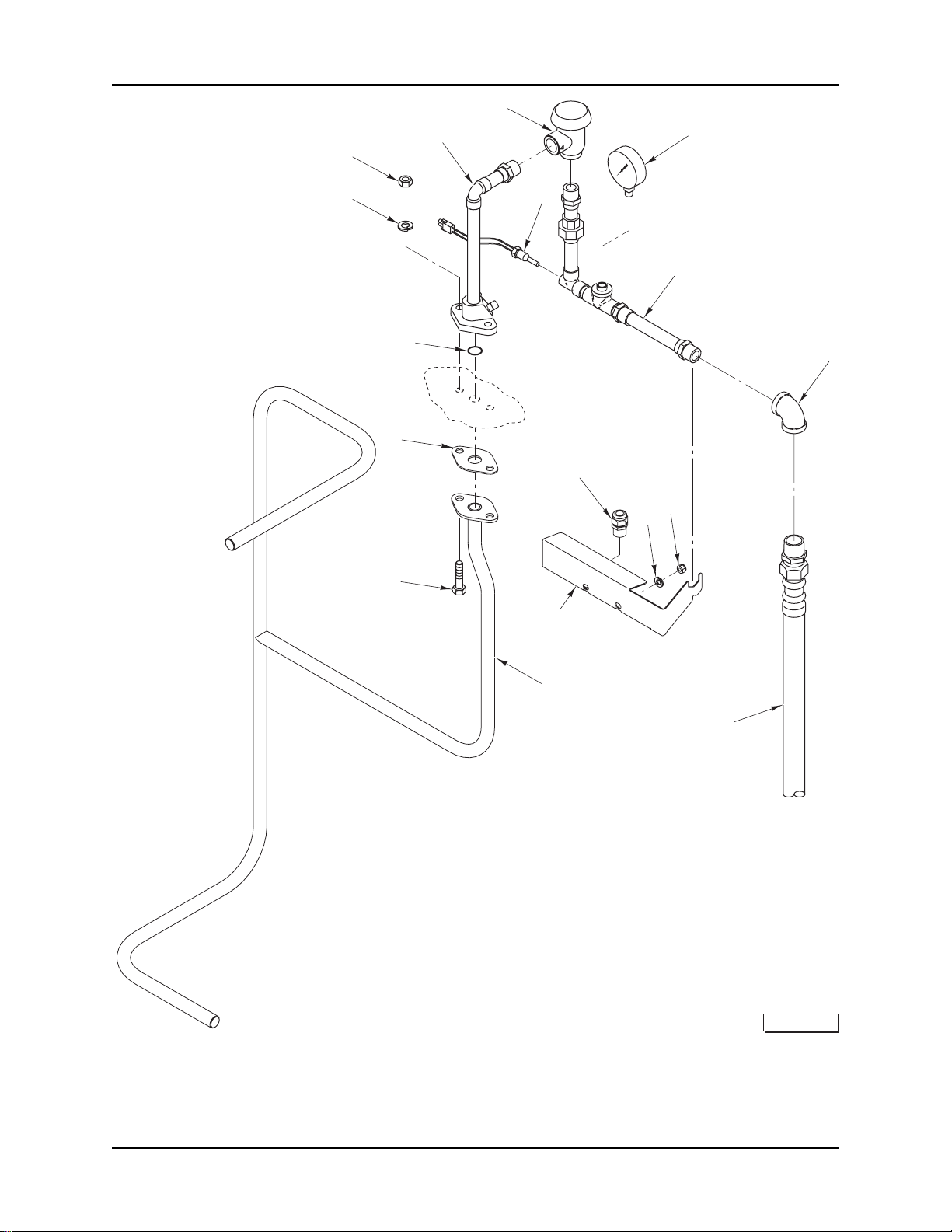
AM15 SERIES DISHWAM15 SERIES DISHW
AM15 Dishwasher Technical Manual Page 54 of 83
AM15 SERIES DISHW
AM15 SERIES DISHWAM15 SERIES DISHW
ASHER REPLACEMENTASHER REPLACEMENT
ASHER REPLACEMENT
ASHER REPLACEMENTASHER REPLACEMENT
2
P P
P
P P
ARAR
AR
ARAR
TSTS
TS
TSTS
4-5
3
7
1
19
18
17
6
8
9
13
11
12
14
INSIDE PIPING INSIDE PIPING
INSIDE PIPING
INSIDE PIPING INSIDE PIPING
15-16
10
AND OUTSIDE RINSE PIPING (W/BOOSTER)AND OUTSIDE RINSE PIPING (W/BOOSTER)
AND OUTSIDE RINSE PIPING (W/BOOSTER)
AND OUTSIDE RINSE PIPING (W/BOOSTER)AND OUTSIDE RINSE PIPING (W/BOOSTER)
PL-57408
F-43094 (October 2004)
- 18 -
Page 55

AM15 SERIES DISHWAM15 SERIES DISHW
AM15 Dishwasher Technical Manual Page 55 of 83
AM15 SERIES DISHW
AM15 SERIES DISHWAM15 SERIES DISHW
ASHER REPLACEMENTASHER REPLACEMENT
ASHER REPLACEMENT
ASHER REPLACEMENTASHER REPLACEMENT
P P
P
P P
ARAR
AR
ARAR
TSTS
TS
TSTS
INSIDE PIPING INSIDE PIPING
INSIDE PIPING
INSIDE PIPING INSIDE PIPING
ILLUS.ILLUS.
ILLUS.
ILLUS.ILLUS.
PL-57408PL-57408
PL-57408
PL-57408PL-57408
1 WL-006-23 Lockwasher 5/16 Helical ............................................................................................................. 2
2 NS-036-19 Stop Nut 5/16-18 Hex ................................................................................................................. 2
3 00-893054 Piping – Fill ............................................................................................................................... 1
4 00-292909 Breaker – Vacuum .................................................................................................................... 1
5 00-292910 Kit – Vacuum Breaker .............................................................................................................. 1
6 00-328994 Probe Assy. – Rinse ................................................................................................................ 1
7 00-328247 Gauge – Water Pressure ......................................................................................................... 1
8 00-893059 Fill Piping Assy.......................................................................................................................... 1
9 FP-015-16 Elbow – Pipe 1/2 x 90 Deg. (Brass) ....................................................................................... 1
10 00-893444-00002 Hose – Water 1/2 x 84 In. Braided (SST) ............................................................................. 1
11 NS-015-11 Nut 5/16-18 Hex .......................................................................................................................... 2
12 WL-006-23 Lockwasher 5/16 Helical ............................................................................................................. 2
13 FE-022-84 Strain Relief ............................................................................................................................... 1
14 00-893053 Bracket – Fill Piping ................................................................................................................. 1
15 00-893038-00001 Inside Rinse Piping Assy. (AM15) .......................................................................................... 1
16 00-893038-00004 Inside Rinse Piping Assy. (AM15T & AM15F) ....................................................................... 1
17 SC-041-12 Cap Screw 5/16-18 x 7/8 Hex Hd. ............................................................................................. 2
18 00-276407 Gasket ........................................................................................................................................ 1
19 00-067500-00012 O-Ring ........................................................................................................................................ 1
PP
ARAR
TT
NO. NO.
P
AR
T
NO.
PP
ARAR
TT
NO. NO.
AND OUTSIDE RINSE PIPING (W/BOOSTER)AND OUTSIDE RINSE PIPING (W/BOOSTER)
AND OUTSIDE RINSE PIPING (W/BOOSTER)
AND OUTSIDE RINSE PIPING (W/BOOSTER)AND OUTSIDE RINSE PIPING (W/BOOSTER)
NAME OF PNAME OF P
NAME OF P
NAME OF PNAME OF P
ARAR
AR
ARAR
TT
T
TT
AMTAMT
AMT
AMTAMT
..
.
..
- 19 -
F-43094 (October 2004)
Page 56

AM15 SERIES DISHWAM15 SERIES DISHW
AM15 Dishwasher Technical Manual Page 56 of 83
AM15 SERIES DISHW
AM15 SERIES DISHWAM15 SERIES DISHW
ASHER REPLACEMENTASHER REPLACEMENT
ASHER REPLACEMENT
ASHER REPLACEMENTASHER REPLACEMENT
P P
P
P P
ARAR
AR
ARAR
TSTS
TS
TSTS
40
12
11
8
7
4-5-6
3
2
1
39
38
35
10
9
16
17
15
13
41
42
36
37
33
32
34
31
28-29-30
27
25
26
24
14
18 THRU 21
22
23
PL-57400
F-43094 (October 2004)
ELECTRIC BOOSTER ELECTRIC BOOSTER
ELECTRIC BOOSTER
ELECTRIC BOOSTER ELECTRIC BOOSTER
- 20 -
TT
ANKANK
T
ANK
TT
ANKANK
Page 57

AM15 SERIES DISHWAM15 SERIES DISHW
AM15 Dishwasher Technical Manual Page 57 of 83
AM15 SERIES DISHW
AM15 SERIES DISHWAM15 SERIES DISHW
ASHER REPLACEMENTASHER REPLACEMENT
ASHER REPLACEMENT
ASHER REPLACEMENTASHER REPLACEMENT
P P
P
P P
ARAR
AR
ARAR
TSTS
TS
TSTS
ELECTRIC BOOSTER ELECTRIC BOOSTER
ELECTRIC BOOSTER
ELECTRIC BOOSTER ELECTRIC BOOSTER
ILLUS.ILLUS.
ILLUS.
ILLUS.ILLUS.
PL-57400PL-57400
PL-57400
PL-57400PL-57400
1 SC-041-01 Cap Screw 1/4-20 x 3/4 Hex Hd. (SST) .................................................................................. 6
2 WL-006-17 Lockwasher 1/4 Medium ............................................................................................................ 6
3 WS-017-06 Washer .......................................................................................................................................6
4 00-749554-00002 Heater (13 kW) (208/240 V.) ................................................................................................... 1
5 00-749554-00003 Heater (13 kW) (480 V.) .......................................................................................................... 1
6 00-749554-00004 Heater (13 kW) (380 V.) .......................................................................................................... 1
7 NS-031-16 Stop Nut 10-24 Hex ................................................................................................................. 2
8 00-475967 Bracket – High Limit ................................................................................................................ 1
9 00-294615-00001 Control – Temperature .............................................................................................................. 1
10 00-749555 Gasket (13 kW) (Electric Heater) ...........................................................................................1
11 00-328994 Probe Assy. – Rinse ................................................................................................................ 1
12 00-893047 Tank – Weldment ...................................................................................................................... 1
13 FP-015-16 Elbow – Pipe 1/2 x 90 Deg. (Brass) ....................................................................................... 1
14 FP-015-16 Elbow – Pipe 1/2 x 90 Deg. (Brass) ....................................................................................... 1
15 NS-036-19 Stop Nut 5/16-18 Hex ................................................................................................................. 3
16 SC-041-11 Cap Screw 5/16-18 x 3/4 Hex Hd. (SST) ................................................................................. 3
17 WS-017-01 Washer .......................................................................................................................................3
18 00-186922 Strainer – Line (3/4 In.) (Brass) ............................................................................................... 1
19 00-186923 Plug – Branch ........................................................................................................................... 1
20 00-186925 Screen – Line Strainer ............................................................................................................. 1
21 00-186924 Gasket – Branch Plug .............................................................................................................. 1
22 FP-027-22 Bushing – Pipe 3/4 to 1/2 .......................................................................................................... 1
23 FP-040-43 Pipe 1/2 x 11/4 TBE (Brass) ...................................................................................................... 1
24 FP-015-17 Elbow – Pipe 1/2 x 90 Deg. (Brass) ....................................................................................... 1
25 FP-022-12 Pipe – Union ............................................................................................................................. 1
26 FP-015-17 Elbow – Pipe 1/2 x 90 Deg. (Brass) ....................................................................................... 1
27 FP-040-43 Pipe 1/2 x 11/4 TBE (Brass) ...................................................................................................... 1
28 00-893100-00001 Valve – Solenoid (1/2 In.) (120 V.) .......................................................................................... 1
29 00-893101 Kit – Water Valve (1/2 In.) ...................................................................................................... AR
30 00-892132 Coil – Solenoid Valve (120 V.) ...............................................................................................1
31 FP-040-43 Pipe 1/2 x 11/4 TBE (Brass) ...................................................................................................... 1
32 FP-028-15 Pipe Plug 1/2 Sq. Hd. ............................................................................................................... 1
33 FP-019-21 Tee – Pipe 1/2 x 1/2 x 1/2 (Brass) ............................................................................................ 1
34 FP-015-17 Elbow – Pipe 1/2 x 90 Deg. (Brass) ....................................................................................... 1
35 FP-040-95 Pipe 1/2 x 7 TBE (Brass) ......................................................................................................... 1
36 NS-031-50 Stop Nut 6-32 Hex (SST) ........................................................................................................ 2
37 00-893082 Bracket – High Limit Protector ................................................................................................ 1
38 00-271123 Protector – High Limit .............................................................................................................. 1
39 SC-021-08 Mach. Screw 6-32 x 3/8 Rd. Hd. (SST) ................................................................................. 2
40 SC-041-11 Cap Screw 5/16-18 x 3/4 Hex Hd. (SST) ................................................................................. 1
41 WS-017-01 Washer .......................................................................................................................................1
42 NS-036-19 Stop Nut 5/16-18 Hex ................................................................................................................. 1
PP
ARAR
TT
NO. NO.
P
AR
T
NO.
PP
ARAR
TT
NO. NO.
00-519504 Lube .......................................................................................................................................... AR
TT
ANKANK
T
ANK
TT
ANKANK
NAME OF PNAME OF P
NAME OF P
NAME OF PNAME OF P
ARAR
AR
ARAR
TT
T
TT
AMTAMT
AMT
AMTAMT
..
.
..
- 21 -
F-43094 (October 2004)
Page 58

AM15 SERIES DISHWAM15 SERIES DISHW
AM15 Dishwasher Technical Manual Page 58 of 83
AM15 SERIES DISHW
AM15 SERIES DISHWAM15 SERIES DISHW
ASHER REPLACEMENTASHER REPLACEMENT
ASHER REPLACEMENT
ASHER REPLACEMENTASHER REPLACEMENT
P P
P
P P
ARAR
AR
ARAR
TSTS
TS
TSTS
5-6-7
4
3
10
2
1
11
13
14
PL-57405
23
22
21
20
19
12
17
18
15
16
8
9
LOW WLOW W
LOW W
LOW WLOW W
F-43094 (October 2004)
AA
TER PROTECTION TER PROTECTION
A
TER PROTECTION
AA
TER PROTECTION TER PROTECTION
- 22 -
AND ELECTRIC HEAAND ELECTRIC HEA
AND ELECTRIC HEA
AND ELECTRIC HEAAND ELECTRIC HEA
TT
T
TT
Page 59

AM15 SERIES DISHWAM15 SERIES DISHW
AM15 Dishwasher Technical Manual Page 59 of 83
AM15 SERIES DISHW
AM15 SERIES DISHWAM15 SERIES DISHW
ASHER REPLACEMENTASHER REPLACEMENT
ASHER REPLACEMENT
ASHER REPLACEMENTASHER REPLACEMENT
P P
P
P P
ARAR
AR
ARAR
TSTS
TS
TSTS
LOW WLOW W
LOW W
LOW WLOW W
ILLUS.ILLUS.
ILLUS.
ILLUS.ILLUS.
PL-57405PL-57405
PL-57405
PL-57405PL-57405
1 NS-014-15 Nut 3/8-16 Hex (Brass) .............................................................................................................. 1
2 WL-006-27 Lockwasher 3/8 Helical .............................................................................................................. 1
3 00-749798 Plate – Electric Heat ................................................................................................................ 1
4 00-067500-00034 O-Ring ........................................................................................................................................ 1
5 00-893120-00001 Element – Heater (5 kW) (200-240 V., 50/60 Hz., 1 & 3 Ph.)..........................................1
6 00-893120-00002 Element – Heater (5 kW) (480 V., 60 Hz., 3 Ph.) .............................................................. 1
7 00-893120-00003 Element – Heater (5 kW) (380-415 V., 50 Hz., 3 Ph.) ....................................................... 1
8 RR-010-13 Retaining Ring ........................................................................................................................... 1
9 00-112467 Retainer – Float ........................................................................................................................ 1
10 00-271621 Probe & Switch Assy. (4 Wire) (Temperatures & Water Level) .......................................... 1
11 00-122674 Float Assy. ................................................................................................................................. 1
12 00-067500-00072 O-Ring ........................................................................................................................................ 1
13 00-119244 Cap & Stud Assy. ..................................................................................................................... 1
14 WS-010-40 Washer .......................................................................................................................................1
15 WL-014-31 Lockwasher 1/2 External Shakeproof (SST) ............................................................................ 1
16 NS-018-28 Jam Nut 1/2-20 Hex .................................................................................................................. 1
17 00-067500-00031 O-Ring ........................................................................................................................................ 1
18 00-119254 Retainer – Cap .......................................................................................................................... 1
19 WL-006-17 Lockwasher 1/4 Helical .............................................................................................................. 1
20 NS-015-01 Nut 1/4-20 Hex ........................................................................................................................... 1
21 00-294615-00001 Control – Temperature .............................................................................................................. 1
22 00-475967 Bracket – High Limit ................................................................................................................ 1
23 NS-031-16 Stop Nut 10-24 Hex ................................................................................................................. 2
PP
ARAR
TT
NO. NO.
P
AR
T
NO.
PP
ARAR
TT
NO. NO.
00-186091 Probe & Float Assy. (Incls. Items 8 thru 11) ........................................................................ 1
00-519504 Lube .......................................................................................................................................... AR
AA
TER PROTECTION TER PROTECTION
A
TER PROTECTION
AA
TER PROTECTION TER PROTECTION
AND ELECTRIC HEAAND ELECTRIC HEA
AND ELECTRIC HEA
AND ELECTRIC HEAAND ELECTRIC HEA
NAME OF PNAME OF P
NAME OF P
NAME OF PNAME OF P
ARAR
AR
ARAR
TT
T
TT
TT
T
TT
AMTAMT
AMT
AMTAMT
..
.
..
- 23 -
F-43094 (October 2004)
Page 60

AM15 SERIES DISHWAM15 SERIES DISHW
AM15 Dishwasher Technical Manual Page 60 of 83
AM15 SERIES DISHW
AM15 SERIES DISHWAM15 SERIES DISHW
1
ASHER REPLACEMENTASHER REPLACEMENT
ASHER REPLACEMENT
ASHER REPLACEMENTASHER REPLACEMENT
P P
P
P P
ARAR
AR
ARAR
TSTS
TS
TSTS
12
11
10
9
8
7
3
4
6
5
2
F-43094 (October 2004)
DRAIN UNITDRAIN UNIT
DRAIN UNIT
DRAIN UNITDRAIN UNIT
- 24 -
PL-57409
Page 61

AM15 SERIES DISHWAM15 SERIES DISHW
AM15 Dishwasher Technical Manual Page 61 of 83
AM15 SERIES DISHW
AM15 SERIES DISHWAM15 SERIES DISHW
DRAIN UNITDRAIN UNIT
DRAIN UNIT
DRAIN UNITDRAIN UNIT
ASHER REPLACEMENTASHER REPLACEMENT
ASHER REPLACEMENT
ASHER REPLACEMENTASHER REPLACEMENT
P P
P
P P
ARAR
AR
ARAR
TSTS
TS
TSTS
ILLUS.ILLUS.
ILLUS.
ILLUS.ILLUS.
PL-57409PL-57409
PL-57409
PL-57409PL-57409
1 00-893045 Strainer Pan ............................................................................................................................... 1
2 NS-047-82 Stop Nut 1/4-20 Hex (SST) ...................................................................................................... 1
3 00-119116 Axle – Drain Lever ................................................................................................................... 1
4 00-893091 Drain Lever Assy....................................................................................................................... 1
5 00-893095 Drain – Lift ................................................................................................................................1
6 SC-066-06 Mach. Screw 10-24 x 1/2 Phil. Truss Hd.
7 00-067500-00120 O-Ring ........................................................................................................................................ 1
8 00-893071 Drain Tube Assy. (Incls. Items 9, 10, & 11) ......................................................................... 1
9 00-893072 Cover – Standpipe .................................................................................................................... 1
10 WS-019-33 Washer .......................................................................................................................................3
11 SD-038-84 Self-Tapping Screw 10-24 x 1/2 Phil. Truss Hd., Type F (SST) .......................................... 3
12 00-118999 Strainer Basket Assy. ............................................................................................................... 1
PP
ARAR
TT
NO. NO.
P
AR
T
NO.
PP
ARAR
TT
NO. NO.
NAME OF PNAME OF P
NAME OF P
NAME OF PNAME OF P
ARAR
AR
ARAR
TT
T
TT
AMTAMT
AMT
AMTAMT
..
.
..
- 25 -
F-43094 (October 2004)
Page 62

AM15 SERIES DISHWAM15 SERIES DISHW
AM15 Dishwasher Technical Manual Page 62 of 83
AM15 SERIES DISHW
AM15 SERIES DISHWAM15 SERIES DISHW
ASHER REPLACEMENTASHER REPLACEMENT
ASHER REPLACEMENT
ASHER REPLACEMENTASHER REPLACEMENT
P P
P
P P
ARAR
AR
ARAR
TSTS
TS
TSTS
13
6
7
5
4
3
2
1
8
9
10
11
12
21
22
20
14
18
19
15
16
17
40
39
42
41
38
37
DOOR DOOR
DOOR
DOOR DOOR
25
26
27
28
29
ASSEMBLASSEMBL
ASSEMBL
ASSEMBLASSEMBL
24
36
35
YY
(AM15) (AM15)
Y
(AM15)
YY
(AM15) (AM15)
34
23
33
32
31
30
PL-57413
F-43094 (October 2004)
- 26 -
Page 63

AM15 SERIES DISHWAM15 SERIES DISHW
AM15 Dishwasher Technical Manual Page 63 of 83
AM15 SERIES DISHW
AM15 SERIES DISHWAM15 SERIES DISHW
ASHER REPLACEMENTASHER REPLACEMENT
ASHER REPLACEMENT
ASHER REPLACEMENTASHER REPLACEMENT
P P
P
P P
ARAR
AR
ARAR
TSTS
TS
TSTS
DOOR DOOR
DOOR
DOOR DOOR
ILLUS.ILLUS.
ILLUS.
ILLUS.ILLUS.
PL-57413PL-57413
PL-57413
PL-57413PL-57413
1 WS-017-01 Washer .......................................................................................................................................2
2 00-893014-00002 Spacer – Door Link (Lower) .................................................................................................... 2
3 WS-017-01 Washer .......................................................................................................................................2
4 NS-036-19 Stop Nut
5 00-893252 Link – Door Handle .................................................................................................................. 2
6 SC-041-12 Cap Screw
7 WS-017-01 Washer .......................................................................................................................................2
8 00-893014-00001 Spacer – Door Link (Upper) .................................................................................................... 2
9 00-893051 Handle – Weldment .................................................................................................................. 1
10 WS-017-01 Washer .......................................................................................................................................2
11 NS-036-19 Stop Nut 5/16-18 Hex ................................................................................................................. 2
12 00-119055 Button – Bearing ....................................................................................................................... 4
13 00-893011 Hanger – Counterbalance (Spring) .......................................................................................... 1
14 00-893012 Spring – Extension (Door) ....................................................................................................... 1
15 00-893013 Hook – Spring ........................................................................................................................... 1
16 NS-015-11 Nut 5/16-18 Hex .......................................................................................................................... 3
17 WS-017-01 Washer .......................................................................................................................................2
18 NS-036-19 Stop Nut 5/16-18 Hex ................................................................................................................. 4
19 00-119055 Button – Bearing ....................................................................................................................... 4
20 00-893224 Support – Handle ...................................................................................................................... 2
21 SC-066-01 Mach. Screw 6-32 x 1/4 Phil Truss Hd. ................................................................................. 2
22 00-111941 Magnet ........................................................................................................................................ 1
23 NS-031-50 Stop Nut 6-32 Hex ................................................................................................................... 2
24 00-893111 Magnet – Mount ........................................................................................................................ 1
25 00-893826 Door Guide Mount .................................................................................................................... 2
26 00-893801 Spacer – Door Guide ............................................................................................................... 2
27 WS-023-01 Washer .......................................................................................................................................4
28 SC-066-02 Mach. Screw 6-32 x 3/8 Phil. Truss Hd. ................................................................................ 4
29 SC-041-09 Cap Screw 5/16-18 x 1/2 Hex Hd. ............................................................................................. 4
30 00-893193-00001 Guide – Door ............................................................................................................................ 2
31 00-893201-00002 Cover – Door Guide (RH) ....................................................................................................... 1
32 NS-047-82 Stop Nut 1/4-20 Hex .................................................................................................................. 4
33 00-473109-00004 Switch Assy. – Door ................................................................................................................. 1
34 NS-015-11 Nut 5/16-18 Hex .......................................................................................................................... 1
35 WL-006-23 Lockwasher 5/16 Helical ............................................................................................................. 1
36 00-893853 Bracket – Reed Switch Mounting ........................................................................................... 1
37 SC-041-11 Cap Screw 5/16-18 x 3/4 Hex Hd. ............................................................................................. 6
38 WL-006-23 Lockwasher 5/16 Helical ............................................................................................................. 6
39 00-893015 Stop – Door ............................................................................................................................... 3
40 00-893201 Cover – Door Guide (LH) ........................................................................................................ 1
41 00-893226 Stiffener – Door Plate .............................................................................................................. 2
42 00-893202 Door Wrap .................................................................................................................................1
PP
ARAR
TT
NO. NO.
P
AR
T
NO.
PP
ARAR
TT
NO. NO.
5
/16-18 Hex ................................................................................................................. 2
ASSEMBLASSEMBL
ASSEMBL
ASSEMBLASSEMBL
5
/16-18 x 7/8 Hex Hd. ............................................................................................. 2
YY
(AM15) (AM15)
Y
(AM15)
YY
(AM15) (AM15)
NAME OF PNAME OF P
NAME OF P
NAME OF PNAME OF P
ARAR
AR
ARAR
TT
T
TT
AMTAMT
AMT
AMTAMT
..
.
..
- 27 -
F-43094 (October 2004)
Page 64

AM15 SERIES DISHWAM15 SERIES DISHW
AM15 Dishwasher Technical Manual Page 64 of 83
AM15 SERIES DISHW
AM15 SERIES DISHWAM15 SERIES DISHW
ASHER REPLACEMENTASHER REPLACEMENT
ASHER REPLACEMENT
ASHER REPLACEMENTASHER REPLACEMENT
P P
P
P P
ARAR
AR
ARAR
TSTS
TS
TSTS
52
3
2
4
5
6
1
54
53
26
27
28
29
30
31
10
8
9
7
32
25
33
24
11
23
22
34
13
12
14
15
16
17
18
19
21
20
35
47
46
45
48
50
49
51
42
43
41
40
44
39
38
36
37
PL-57412
F-43094 (October 2004)
DOOR DOOR
DOOR
DOOR DOOR
ASSEMBLASSEMBL
ASSEMBL
ASSEMBLASSEMBL
YY
(AM15T (AM15T
Y
(AM15T
YY
(AM15T (AM15T
- 28 -
& &
&
& &
AM15F)AM15F)
AM15F)
AM15F)AM15F)
Page 65

AM15 SERIES DISHWAM15 SERIES DISHW
AM15 Dishwasher Technical Manual Page 65 of 83
AM15 SERIES DISHW
AM15 SERIES DISHWAM15 SERIES DISHW
ASHER REPLACEMENTASHER REPLACEMENT
ASHER REPLACEMENT
ASHER REPLACEMENTASHER REPLACEMENT
P P
P
P P
ARAR
AR
ARAR
TSTS
TS
TSTS
DOOR DOOR
DOOR
DOOR DOOR
ILLUS.ILLUS.
ILLUS.
ILLUS.ILLUS.
PL-57412PL-57412
PL-57412
PL-57412PL-57412
1 00-893326 Door Wrap .................................................................................................................................1
2 00-893226 Stiffener – Door Plate .............................................................................................................. 2
3 SC-066-01 Mach. Screw 6-32 x 1/4 Phil. Truss Hd. ................................................................................ 4
4 00-111941 Magnet ........................................................................................................................................ 1
5 00-893111 Magnet – Mount ........................................................................................................................ 1
6 NS-031-50 Stop Nut 5/16-18 Hex ................................................................................................................. 2
7 WS-017-01 Washer .......................................................................................................................................2
8 NS-036-19 Stop Nut 5/16-18 Hex ................................................................................................................. 2
9 WS-017-01 Washer .......................................................................................................................................2
10 00-893486-00002 Bracket – Handle (LH) ............................................................................................................. 1
11 WL-006-23 Lockwasher 5/16 Helical ............................................................................................................. 4
12 SC-041-09 Cap Screw 5/16-18 x 1/2 Hex Hd. ............................................................................................. 4
13 00-119055 Button – Bearing ....................................................................................................................... 4
14 00-893500 Hanger – Counterbalance (Spring) .......................................................................................... 1
15 00-893486-00001 Bracket – Handle (RH)............................................................................................................. 1
16 00-893498 Spring – Extension (Door) ....................................................................................................... 1
17 00-893484 Handle – Weldment .................................................................................................................. 1
18 00-893013-00002 Hook – Spring ........................................................................................................................... 1
19 NS-015-11 Nut 5/16-18 Hex .......................................................................................................................... 3
20 WS-017-01 Washer .......................................................................................................................................2
21 00-918049 Plug – Lift Arm .........................................................................................................................2
22 NS-036-19 Stop Nut 5/16-18 Hex ................................................................................................................. 2
23 WS-017-01 Washer .......................................................................................................................................2
24 00-893014-00001 Spacer Door Link (Upper) ........................................................................................................ 2
25 WS-017-01 Washer .......................................................................................................................................2
26 00-893826 Door Guide Mount .................................................................................................................... 2
27 00-893801 Spacer – Door Guide ............................................................................................................... 2
28 WS-023-01 Washer .......................................................................................................................................4
29 SC-066-02 Mach. Screw 6-32 x 3/8 Phil. Truss Hd. ................................................................................ 4
30 00-893487 Link – Door Handle .................................................................................................................. 2
31 NS-036-19 Stop Nut 5/16-18 Hex ................................................................................................................. 2
32 WS-017-01 Washer .......................................................................................................................................2
33 00-893014-00003 Spacer – Door Link .................................................................................................................. 2
34 WS-017-01 Washer .......................................................................................................................................2
35 SC-041-12 Cap Screw 5/16-18 x 7/8 Hex Hd. ............................................................................................. 2
36 00-473109-00004 Switch Assy. – Door ................................................................................................................. 1
37 NS-015-11 Nut 5/16-18 Hex .......................................................................................................................... 1
38 WL-006-23 Lockwasher 5/16 Helical ............................................................................................................. 1
39 00-893853 Bracket – Reed Switch Mounting ........................................................................................... 1
40 00-893193-00003 Guide – Door (Upper) .............................................................................................................. 2
41 00-893314-00002 Cover – Door Guide (RH) ....................................................................................................... 1
42 00-893946 Vent – Deflector ........................................................................................................................ 1
43 NS-047-82 Stop Nut 1/4-20 Hex .................................................................................................................. 5
44 00-893193-00002 Guide – Door ............................................................................................................................ 2
45 SC-041-09 Cap Screw 5/16-18 x 1/2 Hex Hd. ............................................................................................. 6
46 WL-006-23 Lockwasher 5/16 Helical ............................................................................................................. 6
47 00-893947 Vent – Deflector (Inside) .......................................................................................................... 1
48 00-893957 Baffle – Vent ............................................................................................................................. 1
49 NS-047-82 Stop Nut 1/4-20 Hex .................................................................................................................. 6
50 NS-047-82 Stop Nut 1/4-20 Hex .................................................................................................................. 5
51 00-526408 Tape – Foam ........................................................................................................................... AR
52 00-893314 Cover – Door Guide (LH) ........................................................................................................ 1
53 00-893956 Cap – Vent ................................................................................................................................ 2
54 00-893320 Cover Assy. – Top Chamber ................................................................................................... 1
PP
ARAR
TT
NO. NO.
P
AR
T
NO.
PP
ARAR
TT
NO. NO.
ASSEMBLASSEMBL
ASSEMBL
ASSEMBLASSEMBL
YY
(AM15T (AM15T
Y
(AM15T
YY
(AM15T (AM15T
NAME OF PNAME OF P
NAME OF P
NAME OF PNAME OF P
& &
&
& &
AM15F)AM15F)
AM15F)
AM15F)AM15F)
ARAR
TT
AR
T
ARAR
TT
AMTAMT
AMT
AMTAMT
..
.
..
- 29 -
F-43094 (October 2004)
Page 66

AM15 SERIES DISHWAM15 SERIES DISHW
AM15 Dishwasher Technical Manual Page 66 of 83
AM15 SERIES DISHW
AM15 SERIES DISHWAM15 SERIES DISHW
ASHER REPLACEMENTASHER REPLACEMENT
ASHER REPLACEMENT
ASHER REPLACEMENTASHER REPLACEMENT
P P
P
P P
ARAR
AR
ARAR
TSTS
TS
TSTS
28
27
29
1-2
26
25
24
3
30
31
32
5
4
6
7
8
9
10
13
20
22
18
19
23
21
PP
ANELS ANELS
P
ANELS
PP
ANELS ANELS
35
34
33
AND RACK SUPPORAND RACK SUPPOR
AND RACK SUPPOR
AND RACK SUPPORAND RACK SUPPOR
16
17
TT
T
TT
11
12
36
15
14
PL-57406
F-43094 (October 2004)
- 30 -
Page 67

PP
AM15 Dishwasher Technical Manual Page 67 of 83
ANELS ANELS
P
ANELS
PP
ANELS ANELS
AM15 SERIES DISHWAM15 SERIES DISHW
AM15 SERIES DISHW
AM15 SERIES DISHWAM15 SERIES DISHW
AND RACK SUPPORAND RACK SUPPOR
AND RACK SUPPOR
AND RACK SUPPORAND RACK SUPPOR
ASHER REPLACEMENTASHER REPLACEMENT
ASHER REPLACEMENT
ASHER REPLACEMENTASHER REPLACEMENT
TT
T
TT
P P
P
P P
ARAR
AR
ARAR
TSTS
TS
TSTS
ILLUS.ILLUS.
ILLUS.
ILLUS.ILLUS.
PL-57406PL-57406
PL-57406
PL-57406PL-57406
1 00-893203 Panel – Splash (AM15) ............................................................................................................ 1
2 00-893096 Panel – Splash (AM15T & AM15F) ........................................................................................2
3 SC-059-29 Cap Screw
4 SC-041-10 Cap Screw 5/16-18 x 1/2 Hex Hd. ............................................................................................. 5
5 00-893798 Rack – Stop Assy..................................................................................................................... 1
6 NS-015-01 Nut 1/4-20 Hex ........................................................................................................................... 1
7 WL-006-17 Lockwasher 1/4 Helical .............................................................................................................. 1
8 00-067500-00031 O-Ring ........................................................................................................................................ 1
9 NS-036-19 Stop Nut 5/16-18 Hex ................................................................................................................. 5
10 00-119254 Retainer – Cap .......................................................................................................................... 1
11 00-119244 Cap & Stud Assy. ..................................................................................................................... 1
12 00-893790-00001 Wireform Assy. .......................................................................................................................... 1
13 NS-047-82 Stop Nut 1/4-20 Hex .................................................................................................................. 4
14 SC-041-50 Cap Screw 1/4-20 x 1/2 Hex Hd. .............................................................................................. 2
15 WL-006-17 Lockwasher 1/4 Helical .............................................................................................................. 2
16 00-893042 Panel – Cover (Right Side) ..................................................................................................... 1
17 00-918097 Kit – Foam Installation ........................................................................................................... AR
18 SC-125-15 Mach. Screw 1/4-20 x 1/2 Phil. Truss Hd. ............................................................................... 2
19 WL-006-17 Lockwasher 1/4 Helical .............................................................................................................. 2
20 00-893041 Panel – Cover (Front) .............................................................................................................. 1
21 00-526454 Tape – Foam ........................................................................................................................... AR
22 00-893069 Baffle – Steam .......................................................................................................................... 1
23 NS-036-19 Stop Nut 5/16-18 Hex ................................................................................................................. 2
24 00-893021 Seal – Extrusion ..................................................................................................................... AR
25 00-893775 Deflector ..................................................................................................................................... 1
26 00-526454 Tape – Foam ........................................................................................................................... AR
27 WL-006-17 Lockwasher 1/4 Helical .............................................................................................................. 2
28 SC-041-50 Cap Screw 1/4-20 x 1/2 Hex Hd. .............................................................................................. 2
29 00-893018 Panel – Cover (Left Side) ....................................................................................................... 1
30 NS-047-82 Stop Nut 1/4-20 Hex .................................................................................................................. 2
31 SC-059-29 Cap Screw 1/4-20 x 1/2 Hex Socket Hd. ................................................................................. 4
32 WS-017-06 Washer .......................................................................................................................................4
33 00-893122-00002 Foot – Flanged (Without Holes) .............................................................................................. 4
34 00-893122-00001 Foot – Flanged (With Holes) ................................................................................................... 4
35 00-893122-00003 Foot – Standard ........................................................................................................................ 4
36 00-438131-061-2 Label – Warning (California) .................................................................................................... 1
PP
ARAR
TT
NO. NO.
P
AR
T
NO.
PP
ARAR
TT
NO. NO.
1
/4-20 x 1/2 Hex Socket Hd. ................................................................................. 2
NAME OF PNAME OF P
NAME OF P
NAME OF PNAME OF P
ARAR
AR
ARAR
TT
T
TT
AMTAMT
AMT
AMTAMT
..
.
..
- 31 -
F-43094 (October 2004)
Page 68

AM15 SERIES DISHWAM15 SERIES DISHW
AM15 Dishwasher Technical Manual Page 68 of 83
AM15 SERIES DISHW
AM15 SERIES DISHWAM15 SERIES DISHW
8
ASHER REPLACEMENTASHER REPLACEMENT
ASHER REPLACEMENT
ASHER REPLACEMENTASHER REPLACEMENT
6
P P
P
P P
ARAR
AR
ARAR
TSTS
TS
TSTS
7
1
2
5
4
3
FRONTFRONT
FRONT
FRONTFRONT
ILLUS.ILLUS.
ILLUS.
ILLUS.ILLUS.
PL-57410PL-57410
PL-57410
PL-57410PL-57410
1 00-893220 Bracket – Splash (Corner) ....................................................................................................... 2
2 00-893096 Panel – Splash .........................................................................................................................2
3 00-893817 Hinge Assy. (RH) ...................................................................................................................... 1
4 00-893815 Tray Weldment ..........................................................................................................................1
5 00-893816 Hinge Assy. (LH) ....................................................................................................................... 1
6 NS-047-82 Stop Nut 1/4-20 Hex .................................................................................................................. 8
7 SC-059-29 Cap Screw 1/4-20 x 1/2 Hex Socket Hd. ................................................................................. 4
8 00-893983 Baffle – Steam .......................................................................................................................... 1
PP
ARAR
TT
NO. NO.
P
AR
T
NO.
PP
ARAR
TT
NO. NO.
TRATRA
TRA
TRATRA
YY
(AM15F) (AM15F)
Y
(AM15F)
YY
(AM15F) (AM15F)
NAME OF PNAME OF P
NAME OF P
NAME OF PNAME OF P
ARAR
AR
ARAR
TT
T
TT
PL-57410
AMTAMT
AMT
AMTAMT
..
.
..
F-43094 (October 2004)
- 32 -
Page 69

AM15 SERIES DISHWAM15 SERIES DISHW
AM15 Dishwasher Technical Manual Page 69 of 83
AM15 SERIES DISHW
AM15 SERIES DISHWAM15 SERIES DISHW
ASHER REPLACEMENTASHER REPLACEMENT
ASHER REPLACEMENT
ASHER REPLACEMENTASHER REPLACEMENT
1-2
3
P P
P
P P
ARAR
AR
ARAR
TSTS
TS
TSTS
19
18
17
16
15
14
13
10
5-6
4
7
8
9
11
GAS HEAGAS HEA
GAS HEA
GAS HEAGAS HEA
TT
PIPING PIPING
T
PIPING
TT
PIPING PIPING
NAME OF PNAME OF P
NAME OF P
NAME OF PNAME OF P
ARAR
AR
ARAR
PL-57411
TT
T
TT
ILLUS.ILLUS.
ILLUS.
ILLUS.ILLUS.
PL-5741PL-5741
PL-5741
PL-5741PL-5741
12
PP
ARAR
TT
NO. NO.
P
AR
T
NO.
PP
ARAR
TT
11
1
11
NO. NO.
1 00-893149-00001 Orifice (NAT) .............................................................................................................................. 1
2 00-893149-00002 Orifice (LP) ................................................................................................................................1
3 00-893132 Adapter 1/2 to 7/16-20 ................................................................................................................. 1
4 FP-059-10 Pipe 1/2 x 3 TBE ....................................................................................................................... 1
5 00-328426-00004 Valve – Regulator (NAT) .......................................................................................................... 1
6 00-328426-00005 Valve – Regulator (LP)............................................................................................................. 1
7 SC-041-10 Cap Screw 5/16-18 x 5/8 Hex Hd. ............................................................................................. 3
8 00-893899 Support – Valve Assy. .............................................................................................................. 1
9 NS-015-11 Nut 5/16-18 Hex .......................................................................................................................... 3
10 00-291988-00003 Valve – Gas (Shut Off) ............................................................................................................ 1
11 FP-067-04 Pipe 1/2 x 17/8 TBE ................................................................................................................... 1
12 FP-013-15 Elbow Pipe 1/2 x 90 Deg. ........................................................................................................ 1
13 FP-067-04 Pipe 1/2 x 17/8 TBE ................................................................................................................... 1
14 FP-022-11 Union – Pipe ............................................................................................................................. 1
15 FP-067-04 Pipe 1/2 x 17/8 TBE ................................................................................................................... 1
16 FP-084-31 Tee Pipe 1/2 x 1/2 x 1/4 .............................................................................................................. 1
17 FP-035-94 Pipe 1/2 x 11/2 TBE .................................................................................................................... 1
18 FP-013-15 Elbow Pipe 1/2 x 90 Deg. ........................................................................................................ 1
19 FP-036-97 Pipe 1/2 x 23/4 TBE ................................................................................................................... 1
00-893896-00001 Gas Piping Assy. (NAT) (Incls. Items 1, 3, 4, 5, & 10 thru 19) ....................................... 1
00-893896-00002 Gas Piping Assy. (LP) (Incls. Items 2, 3, 4, 6, & 10 thru 19) .......................................... 1
- 33 -
F-43094 (October 2004)
AMTAMT
AMT
AMTAMT
..
.
..
Page 70

AM15 SERIES DISHWAM15 SERIES DISHW
AM15 Dishwasher Technical Manual Page 70 of 83
AM15 SERIES DISHW
AM15 SERIES DISHWAM15 SERIES DISHW
ASHER REPLACEMENTASHER REPLACEMENT
ASHER REPLACEMENT
ASHER REPLACEMENTASHER REPLACEMENT
P P
P
P P
ARAR
AR
ARAR
TSTS
TS
TSTS
35
28-29
40
36
41
39
38
37
34
42
33
32
31
30
13
12
11
10
43
1
2
3
4
5
6
27
26
25
24
23
22
20
21
F-43094 (October 2004)
19
18
16
17
15
GAS HEAGAS HEA
GAS HEA
GAS HEAGAS HEA
14
TT
COMPONENTS COMPONENTS
T
COMPONENTS
TT
COMPONENTS COMPONENTS
- 34 -
7
8
9
PL-57415
Page 71

AM15 SERIES DISHWAM15 SERIES DISHW
AM15 Dishwasher Technical Manual Page 71 of 83
AM15 SERIES DISHW
AM15 SERIES DISHWAM15 SERIES DISHW
ASHER REPLACEMENTASHER REPLACEMENT
ASHER REPLACEMENT
ASHER REPLACEMENTASHER REPLACEMENT
P P
P
P P
ARAR
AR
ARAR
TSTS
TS
TSTS
GAS HEAGAS HEA
GAS HEA
GAS HEAGAS HEA
ILLUS.ILLUS.
ILLUS.
ILLUS.ILLUS.
PL-57415PL-57415
PL-57415
PL-57415PL-57415
1 NS-031-21 Stop Nut 1/4-20 Hex .................................................................................................................. 6
2 WL-014-10 Lockwasher 1/4 External ............................................................................................................ 6
3 00-893890 Shroud – Exhaust ..................................................................................................................... 1
4 NS-015-13 Nut 3/8-16 Hex ........................................................................................................................... 4
5 WL-006-28 Lockwasher 3/8 Helical .............................................................................................................. 4
6 WS-028-22 Washer .......................................................................................................................................4
7 00-893892 Gasket – Immersion Tube ....................................................................................................... 1
8 00-893879 Tube – Immersion ..................................................................................................................... 1
9 00-893900 Turbulator – Immersion Tube .................................................................................................. 1
10 WS-028-22 Washer .......................................................................................................................................4
11 SC-041-31 Cap Screw 3/8-16 x 11/4 Hex Hd. ............................................................................................ 4
12 SC-041-31 Cap Screw 3/8-16 x 11/4 Hex Hd. ............................................................................................ 4
13 WS-028-22 Washer .......................................................................................................................................4
14 00-893891 Gasket – Immersion tube ........................................................................................................ 1
15 00-893897 Burner – Infrared ......................................................................................................................1
16 00-748571-00002 Ignitor (With Terminals)............................................................................................................. 1
17 WL-006-02 Lockwasher #8 Helical .............................................................................................................1
18 SC-021-13 Mach. Screw 8-32 x 1/4 Slotted Rd. Hd. ............................................................................... 1
19 00-748572 Electrode Assy. .......................................................................................................................... 1
20 WL-006-02 Lockwasher #8 Helical .............................................................................................................1
21 SC-021-13 Mach. Screw 8-32 x 1/4 Slotted Rd. Hd. ............................................................................... 1
22 NS-031-21 Stop Nut 1/4-20 Hex .................................................................................................................. 4
23 WL-014-10 Lockwasher 1/4 External ............................................................................................................ 4
24 NS-015-13 Nut 3/8-16 Hex ........................................................................................................................... 4
25 WL-006-28 Lockwasher 3/8 Helical .............................................................................................................. 4
26 WS-028-22 Washer .......................................................................................................................................4
27 00-918034 Seal – Blower/Burner ................................................................................................................ 1
28 00-893893-00001 Plate – Reducer (NAT).............................................................................................................1
29 00-893893-00002 Plate – Reducer (LP) ............................................................................................................... 1
30 NS-031-50 Stop Nut 6-32 Hex ................................................................................................................... 2
31 00-271123 Protector – High Limit .............................................................................................................. 1
32 SC-021-08 Mach. Screw 6-32 x 3/8 Slotted Rd. Hd. ............................................................................... 2
33 SC-041-05 Cap Screw 1/4-20 x 5/8 Hex Hd. .............................................................................................. 4
34 00-918034 Seal – Blower/Burner ................................................................................................................ 1
35 00-893898 Blower – Gas ............................................................................................................................ 1
36 NS-031-21 Stop Nut 1/4-20 Hex .................................................................................................................. 2
37 00-748562-00002 Switch – Air ............................................................................................................................... 1
38 SD-038-02 Self-Tapping Screw 6-20 x 5/8 Phil. Pan Hd., Type B ......................................................... 2
39 00-748512 Board – Ignitor (24 VAC) ......................................................................................................... 1
40 SC-041-10 Cap Screw 5/16-18 x 5/8 Hex Hd. ............................................................................................. 2
41 00-893895 Bracket – Ignitor Board ............................................................................................................ 1
42 NS-015-11 Nut 5/16-18 Hex .......................................................................................................................... 2
43 00-893887 Baffle – Exhaust ....................................................................................................................... 3
PP
ARAR
TT
NO. NO.
P
AR
T
NO.
PP
ARAR
TT
NO. NO.
TT
COMPONENTS COMPONENTS
T
COMPONENTS
TT
COMPONENTS COMPONENTS
NAME OF PNAME OF P
NAME OF P
NAME OF PNAME OF P
ARAR
AR
ARAR
TT
T
TT
AMTAMT
AMT
AMTAMT
..
.
..
- 35 -
F-43094 (October 2004)
Page 72

AM15 SERIES DISHWAM15 SERIES DISHW
AM15 Dishwasher Technical Manual Page 72 of 83
AM15 SERIES DISHW
AM15 SERIES DISHWAM15 SERIES DISHW
ASHER REPLACEMENTASHER REPLACEMENT
ASHER REPLACEMENT
ASHER REPLACEMENTASHER REPLACEMENT
P P
P
P P
ARAR
AR
ARAR
TSTS
TS
TSTS
2
PL-53023
DISH RACKSDISH RACKS
DISH RACKS
DISH RACKSDISH RACKS
ILLUS.ILLUS.
ILLUS.
ILLUS.ILLUS.
PL-53023PL-53023
PL-53023
PL-53023PL-53023
1 00-315191 Rack – Peg (Packaged) ........................................................................................................... 1
2 00-315193 Rack – Combination (Packaged) ............................................................................................. 1
FORM 43094FORM 43094
FORM 43094
FORM 43094FORM 43094
PP
ARAR
TT
NO. NO.
P
AR
T
NO.
PP
ARAR
TT
NO. NO.
00-295288 Peg Type Tray Rack (Packaged)............................................................................................ 1
00-892671 Rack – Bun Pan .......................................................................................................................1
00-474800 Rack (6 Pan) ............................................................................................................................. 1
OCTOCT
OBER 2004OBER 2004
OCT
OBER 2004
OCTOCT
OBER 2004OBER 2004
NAME OF PNAME OF P
NAME OF P
NAME OF PNAME OF P
ARAR
AR
ARAR
TT
T
TT
PRINTED IN U.S.A.PRINTED IN U.S.A.
PRINTED IN U.S.A.
PRINTED IN U.S.A.PRINTED IN U.S.A.
1
AMTAMT
..
AMT
.
AMTAMT
..
Page 73

Online Parts Catalog
AM15 Dishwasher Technical Manual Page 73 of 83
Note: It is helpful, but not essential to know
the ML (Material List) Number of the
equipment for which a part is needed
User Guide
Section 1 – If Equipment ML Number is known
Section 2 – If Equipment ML Number is not known
Page 74

From
AM15 Dishwasher Technical Manual Page 74 of 83
hobartservice.com
select
PARTS
User Guide
Web Browser Pop-up blocker must be turned off for this site in order for SmartParts to operate
Next
select
SMARTPARTS
Page 75

This is SmartParts
AM15 Dishwasher Technical Manual Page 75 of 83
home page
If the ML Number of
the Equipment is
known,
select
Use SmartParts Now
(We’ll explain what to
do if the ML number of
the Equipment is not
known in Section 2)
104352
104352
Enter the ML number
and click on
Search SmartParts
For this example, the part needed is a Water
Pressure Gauge used on the LX 30 Undercounter
Dishwasher
The ML number of this dishwasher is 104352
Section 1 – If Equipment ML Number is known
Page 76

Click on the
AM15 Dishwasher Technical Manual Page 76 of 83
Radio button
to select the
Parts Catalog
•
Then click on
Continue
The Water Pressure Gauge is
on the Base Assembly
Section 1 – If Equipment ML Number is known
Select Base Assembly
Then click on Continue
Page 77

•
AM15 Dishwasher Technical Manual Page 77 of 83
Select an appropriate figure size
19: Gauge – Water Pressure (LX30/40, LXG, & LXiG Series)
Locate the part needed (Water
Pressure Gauge) on the drawing
Placing the cursor on the number
will display the Description of the
Part
Click on the number pointing to
the part
Section 1 – If Equipment ML Number is known
Page 78

• Selecting the part on the figure causes the part to be highlighted on the parts list
AM15 Dishwasher Technical Manual Page 78 of 83
• Click on the Add button to add the part to the shopping cart
• You can add more parts or change the quantity of the parts already in the cart
• When finished, click on the Confirm Parts Selected and then on Print Parts List if
you want to print
Section 1 – If Equipment ML Number is known
Use SMARTPARTS Now
Page 79

This (again) is SmartParts
AM15 Dishwasher Technical Manual Page 79 of 83
home page
For this example, the part
needed is a Water
Pressure Gauge used on
the LX 30 Undercounter
Dishwasher
If the ML Number of the
Equipment is not known,
click on the Radio button
to select Warewash /
Waste Equipment
Then click on Continue
(Go to Section 1 if you do know
the ML number of the
Equipment)
Section 2 – If Equipment ML Number is not known
Click on the Radio button
to select UnderCounter
Dishwasher
Then click on
Continue
Page 80

Click on the Radio button
AM15 Dishwasher Technical Manual Page 80 of 83
to select LX Series
Dishwashers
Then click on
Continue
The Water Pressure Gauge
is on the Base Assembly
Select Base Assembly
Then click on Continue
Section 2 – If Equipment ML Number is not known
Page 81

Select an appropriate figure size
AM15 Dishwasher Technical Manual Page 81 of 83
19: Gauge – Water Pressure (LX30/40, LXG, & LXiG Series)
Locate the part needed (Water
Pressure Gauge) on the
drawing
Placing the cursor on the
number will display the
Description of the Part
Click on the number pointing to
the part
Section 2 – If Equipment ML Number is not known
Page 82

• Selecting the part on the figure causes the part to be highlighted on the parts list
AM15 Dishwasher Technical Manual Page 82 of 83
• Click on the Add button to add the part to the shopping cart
• You can add more parts or change the quantity of the parts already in the cart
• When finished, click on the Confirm Parts Selected and then on Print Parts List if
you want to print
Section 2 – If Equipment ML Number is not known
Use SMARTPARTS Now
Page 83

AM15-2 DISHWASHER
AM15 Dishwasher Technical Manual Page 83 of 83
NOVEMBER 2009
PRODUCT SERVICE DEPARTMENT TROY, OH. 45374-0001
RECOMMENDED SPARE PARTS LIST
AM15-2 DISHWASHER
ELECTRIC TANK HEAT (208-240/60/3)
Qty. Part Number Description
1 892458 Display Module, AM15
1 893113 Switch, Membrane Keypad, AM15
1 294500-51 Transformer, 30VA, 50/60 Hz
1 294500-52-1 Transformer, 100VA, 50/60 Hz
1 892932 Control Board
1 892934-1 Relay Board
5 FE-22-29 Fuse, 250V, 1.0 Amp
3 FE-26-30 Fuse, 250V, 0.1 Amp
1 87713-41-2 Contactor - 40 Amp, 3 Pole
1 186091 Probe & Float Assy
1 328994 Rinse Probe Assy
1 893039-8 Pump Motor, 3-Phase
1 274227-6 Shaft Seal
1 893120-1 Wash Tank Heater, 5KW, 208-240 Volt
1 294615-1 Temperature Control (Wash Tank Heat & Booster)
1 749554-2 Booster Heater Element, 13KW, 208-240 Volt
1 749555 Gasket - Booster Heater Element
1 271123 High Limit Protector (Booster Heater)
1 473109-4 Door Switch Assy
1 893100-1 Water Solenoid Valve, 1/2", 120 Volt
1 893101 Repair Kit - 1/2" Solenoid Valve
1 292910 Vacuum Breaker Kit, 1/2"
5 67500-120 Oring (Drain)
AM15-2Page 1 of 1
 Loading...