

Page 1
Liquid Crystal Projector
CPX880/CPX885
USER'S MANUAL Vol.1 Basic
Please read this user's manual thoroughly to ensure correct usage through understanding.
BEDIENUNGSANLEITUNG Teil 1 Grundlagen
Bitte lessen Sie diese Benutzerhandbuch zugunsten der korrekten Bedienung aufmerksam.
MANUEL D'UTILISATION Vol.1 Fondements
Nous vous recommandons de lire attentivement ce manuel pour bien assimiler le fonctionnement de l'appareil.
MANUALE D'ISTRUZIONI Vol.1 Informazioni di base
Vi preghiamo voler leggere attentamente il manuale d'istruzioni in modo tale da poter comprendere quanto riportato
ai fini di un corretto utilizzo del proiettore.
MANUAL DE USUARIO Vol.1 Básico
Lea cuidadosamente este manual del usuario para poder utilizar corretamente el producto.
GEBRUIKSAANWIJZING Vol.1 Basis
Lees voor het qebruik alstublieft deze handleiding aandachtig door, om volledig profijt te hebben van de
uitgebreide mogelijkheden.
BRUKERHÅNDBOK Vol.1 Grunnleggende
Vennligst les denne bruksanvisningen grundig for å være garantert driftssikker bruk.
INSTRUÇÕES DO PROPRIETÁRIO Vol.1 Básico
Para assegurar o uso correto do equipamento, por favor leia atentamente este manual do utilizador.
ENGLISH
DEUTSCH
FRANÇAIS
ITALIANO
ESPAÑOL
NEDERLANDS
NORSK
PORTGÊS
Page 2

LCD Projector CP-X880/CP-X885
USER'S MANUAL Vol.1 (Basic)
USER'S MANUAL
Thank you for purchasing this projector.
WARNING • Please read the accompanying manual “SAFETY
INSTRUCTIONS” and this “USER'S MANUAL” thoroughly to ensure correct
usage through understanding. After reading, store this instruction manual in a
safe place for future reference.
NOTE
• The manufacturer assumes no responsibility for any errors that may appear in this manual
• The reproduction, transmission or use of this document or contents is not permitted without express
written authority.
TRADEMARK ACKNOWLEDGEMENT :
• PS/2, VGA and XGA are registered trademarks of the International Business Machines Corporation.
• Apple, Mac and ADB are registered trademarks of Apple Computer, Inc.
• VESA and SVGA are trademarks of the Video Electronics Standard Association.
• Windows is a registered trademark of Microsoft Corporation.
• All other trademarks are the property of their respective owners.
• The information in this manual is subject to change without notice.
CONTENTS
Page
PROJECTOR FEATURES................2
PREPARATIONS ..............................2
PART NAMES...................................4
SETTING UP
THE PROJECTOR ............................6
CONNECTING
YOUR DEVICES................................8
USING THE REMOTE
CONTROL.......................................13
TURNING ON THE POWER ...........15
TURNING OFF THE POWER .........17
ADJUSTING THE VOLUME ...........18
TEMPORARILY MUTING
THE SOUND....................................18
ADJUSTING THE POSITION..........19
USING THE AUTOMATIC
ADJUSTMENT FEATURE ..............20
CORRECTING KEYSTONE
DISTORTIONS ................................21
USING THE MAGNIFY
FEATURE........................................22
FREEZING THE SCREEN ..............22
ADJUSTING SCREEN WITH
ONE-TOUCH...................................23
SELECTING THE ASPECT
RATIO..............................................24
TEMPORARILY BLANKING
THE SCREEN..................................24
DISPLAYING CHILD WINDOW
(P. IN. P: Picture in Picture) ..........24
USING THE MENU
FUNCTIONS....................................25
OPERATING THE PC SCREEN .....26
THE LAMP ......................................27
THE AIR FILTER.............................29
OTHER CARE.................................31
Page
1
Page 3
PROJECTOR
FEATURES
This liquid crystal projector is used to project
various computer signals as well as NTSC / PAL /
SECAM video signals onto a screen. Little space
is required for installation and large images can
easily be realized.
Ultra High Brightness
●
Crisp, ultra-bright presentations is achieved
by using a UHB (ultra high brightness) lamp
and a highly efficient optical system
Partial Magnification Function
●
Interesting parts of images can be magnified
for closer viewing
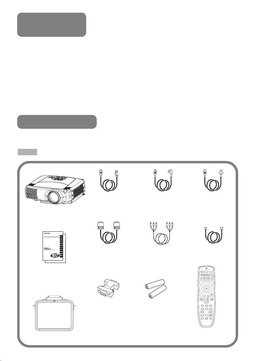
PREPARATIONS
Your projector should come with the items
shown below. Check to make sure that all the
items are included. Contact your dealer if
anything is missing.
NOTE
• Keep the original packing material for future reshipment.
Power cord
(US Type)
Projector
(with Lens Cap)
Liquid Crystal Projector
CP-X880/CP-X885
ENGLISH
(CP-X880W/CP-X885W)
USER'S MANUALVol.1 Basic
DEUTSCH
Please read this user's manual thoroughly to ensure correct usage through understanding.
BEDIENUNGSANLEITUNG Teil 1 Grundlagen
Bitte lessen Sie diese Benutzerhandbuch zugunsten der korrekten Bedienung aufmerksam.
MANUEL D'UTILISATION Vol.1 Fondements
FRANÇAIS
Nous vous recommandons de lire attentivement ce manuel pour bien assimiler le fonctionnement de
l'appareil.
MANUALE D'ISTRUZIONI Vol.1 Informazioni di base
Vi preghiamo voler leggere attentamente il manuale d'istruzioni in modo tale da poter comprendere
ITALIANO
quanto riportato ai fini di un corretto utilizzo del proiettore.
MANUAL DE USUARIO Vol.1 Básico
Lea cuidadosamente este manual del usuario para poder utilizar corretamente el producto.
ESPAÑOL
GEBRUIKSAANWIJZING Vol.1 Basis
Lees voor het qebruik alstublieft deze handleiding aandachtig door, om volledig profijt te hebben van
de uitgebreide mogelijkheden.
BRUKERHÅNDBOK Vol.1 Grunnleggende
Vennligst les denne bruksanvisningen grundig for å være garantert driftssikker bruk.
NEDERLANDS
NSTRUÇÕES DO PROPRIETÁRIO Vol.1 Básico
Para assegurar o uso correto do equipamento, por favor leia atentamente este manual do utilizador.
NORSK
PORTGÊS
中中文文
REGULATORY
NOTICES
RGB cable USB mouse
One Touch Function
●
Just press the ONE TOUCH button to
automatically retrieve input signals, calibrate
images, and correct keystone distortion
Whisper Mode Equipped
●
Special mode is available for reducing
projector noise to achieve quieter operation
Power cord
(UK Type)
Power cord
(Europe Type)
Video/Audio cable
cable
User's Manuals
(Vol.1/Vol.2)
Safety Instructions
Soft carrying case
2
RS-232C
adapter
Two AA batteries
(for the remote
control)
LASER
INDICATOR
VIDEO
RGB
STANDBY/ON
UP
PAGE
ZOOM
FOCUS
DOWN
BLANK
LASER
ASPECT
PUSH
ENTER
ESC MENU RESET
POSITION
AUTO
PinP
MAGNIFY VOLUME
ON
FREEZE
MUTE
OFF
WIRELESS KEYSTONE
ONE TOUCH
Remote control
Page 4

WARNING Precautions to observe in regards to the power cord: Please use extra
caution when connecting the projector's power cord as incorrect or faulty
connections may result in FIRE AND/OR ELECTRICAL SHOCK. Please adhere to the
following safety guidelines to insure safe operation of the projector:
•
Only plug the power cord into outlets rated for use with the power cord's specified voltage range.
• Only use the power cord that came with the projector.
• NEVER ATTEMPT TO DEFEAT THE GROUND CONNECTION OF THE THREE-
PRONGED PLUG!
• Make sure that you firmly connect the power cord to the projector and wall outlet.
Connect your devices to the projector
1
Connect your computer, VCR and/or other
devices you will be using to the projector.
Insert the batteries into the remote
2
control
Connect the power cord
3
(1)
Connect the connector of the electrical power cord to the AC inlet of the main unit.
(2) Firmly plug the power cord's plug into the outlet
8 12
〜
13
Power outlet
AC inlet
(1)
(2)
Power cord
3
Page 5

PART NAMES
STANDBY/ON
INPUT
KEYSTONE
RESET
MENU
LANP
TENP
ONE TOUCH
RGB
BNC
DVI
VIDEO
S-VIDEO
COMPONENT
FOCUS ZOOM
RGB indicator
BNC indicator
DVI indicator
VIDEO indicator
S-VIDEO indicator
COMPONENT indicator
16
16
16
16
THE PROJECTOR
INPUT dial
16
16
16
KEYSTONE button
21
22
Indicates the
corresponding
reference page
ONE TOUCH button
RESET button
19
FOCUS button
16
ZOOM
16
MENU button
25
Vol.2
LAMP indicator
9
button
STANDBY/ON button
Elevator feet
6
Lens cap
COMPONENT VIDEO port
CONTROL port
WIRELESS & NETWORK
MODULE port Vol.2
RGB OUT port
DVI port
RGB port
11
10
15
15
12
Control Panel
10
7
12
15
Vol.2
14
Lens
REMOTE CONTROL port
14
12
Elevator button
6
VIDEO IN port
12
TEMP indicator
9
Elevator screw
6
Air filter
29
Remote sensor
S-VIDEO IN port
Remote sensor
14
AC power inlet
3
4
BNC port
AUDIO IN R/L port
11
12
9
AUDIO IN 1/2 port
10
Power switch
15
USB port
10
AUDIO OUT port
Page 6
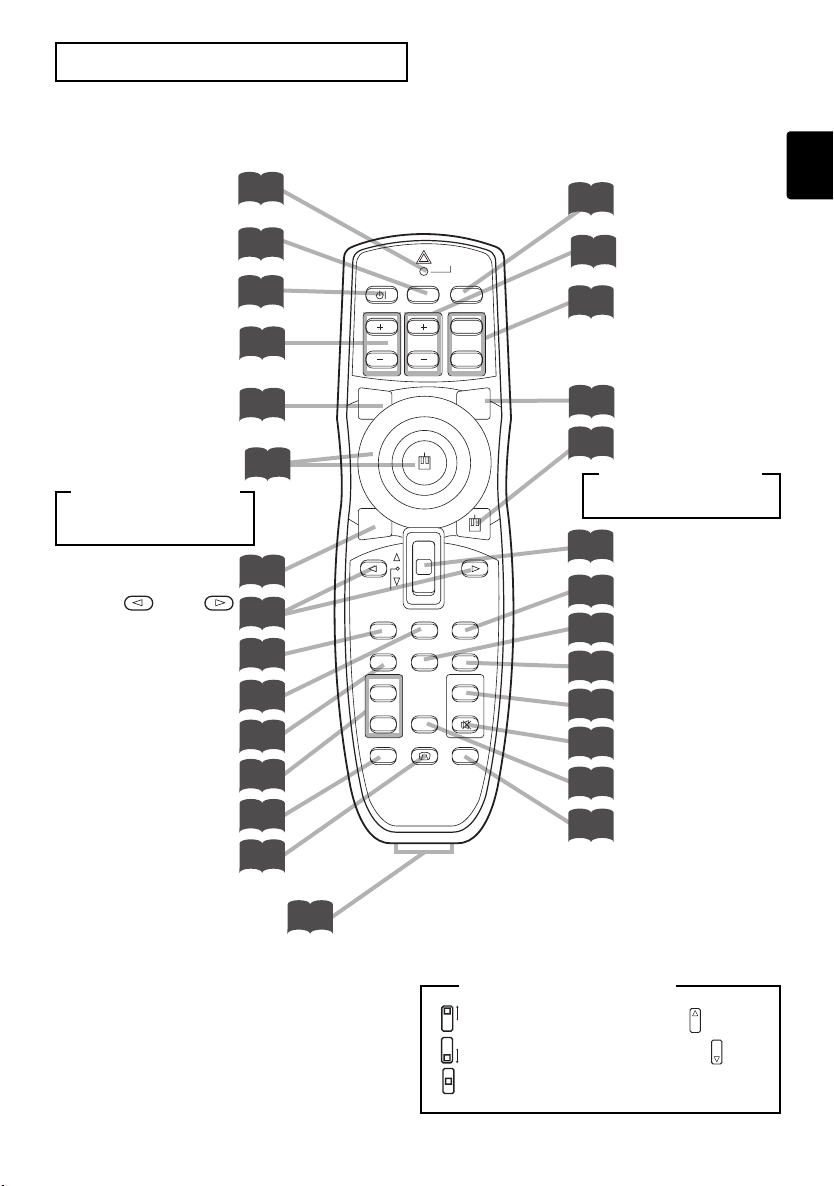
THE REMOTE CONTROL
LASER INDICATOR
VIDEO button
STANDBY/ON button
FOCUS buttons
BLANK button
Disk pad
<For mouse control>
Mouse cursor movement
Left mouse click
ASPECT button
Left /Right
Key buttons
ESC button
MENU button
POSITION button
MAGNIFY buttons
WIRELESS button Vol.2
KEYSTONE button
14
16
15
16
24
26
24
25
25
25
19
22
7
21
LASER
INDICATOR
VIDEO
ZOOM
AUTO
FREEZE
RGB
PAGE
DOWN
PinP
MUTE
ONE TOUCH
STANDBY/ON
FOCUS
BLANK
ASPECT
PUSH
ENTER
ESC MENU RESET
POSITION
MAGNIFY VOLUME
ON
OFF
WIRELESS KEYSTONE
UP
LASER
RGB button
16
ZOOM
16
26
14
26
<For mouse control>
buttons
PAGE buttons
LASER button
Right mouse button
Right mouse click
Lever switch (*)
25
RESET button
19
AUTO button
20
PinP button
24
VOLUME button
18
MUTE button
18
FREEZE button
22
ONE TOUCH button
23
REMOTE CONTROL port
14
* Using the lever switch
Flip toward disk pad : Up ( ) key
Flip toward MENU button
Press in center : ENTER button
: Down ( ) key
5
Page 7

SETTING UP THE PROJECTOR
CAUTION •
of the accompanying manual “SAFETY INSTRUCTIONS” and this manual.
• If you press the elevator buttons without holding the projector, the projector might
crash down, overturn, smash your fingers and possibly result in malfunction. To
prevent damaging the projector and injuring yourself, ALWAYS HOLD THE
PROJECTOR whenever using the elevator buttons to adjust the elevator feet.
Install the projector in a suitable environment according to instructions
Adjusting the Projector's Elevator Feet
If the surface on which the projector is placed, or the screen is tilted, use the
elevator feet and elevator screw to adjust the projection angle of the main unit.
The adjustment range of the elevator feet is 0 to 9 degrees.
Press and hold in the elevator
1
buttons
Elevator button
Raise or lower the projector to the
2
desired height and then release the
elevator buttons
When you release the elevator buttons, the elevator
feet will lock into position.
Elevator feet
Turn the elevator screw to fine tune.
3
Elevator screw
6
Page 8

Adjusting the Screen Size and Projection Distance
Refer to the illustrations and tables below to determine the screen size and
projection distance.
The values shown in the table are calculated for a full size screen
a:Distance from the projector to the screen (±10%)
b:Distance from the lens center to the bottom of the screen (±10%)
c:Distance from the lens center to the top of the screen (±10%)
The screen
Lens center
c
The screen
Top view
Side view
a
Top view
If 4:3 aspect ratio
4
3
Screen Size [inch (m)]
30 (0.8) 34 (0.9) 52 (1.3) 0 (0) 18 (46)
40 (1.0) 46 (1.2) 71 (1.8) 0 (0) 24 (61)
50 (1.3) 58 (1.5) 89 (2.3) 0 (0) 30 (76)
60 (1.5) 71 (1.8)
70 (1.8) 83 (2.1)
80 (2.0) 95 (2.4)
90 (2.3)
100 (2.5)
120 (3.0)
150 (3.8)
200 (5.0)
250 (6.3)
300 (7.5)
a [inch (m)]
Min. Max.
107 (2.7)
126 (3.2)
144 (3.7)
108 (2.7) 162 (4.1)
120 (3.0) 181 (4.6)
144 (3.7) 217 (5.5)
181 (4.6) 272 (6.9)
243 (6.2) 364 (9.2)
304 (7.7)
455 (11.6)
366 (9.3)
547 (13.9)
If 16:9 aspect ratio
16
9
b
[inch (cm)]c [inch (cm)]
0 (0) 36 (91)
0 (0) 42 (107)
0 (0) 48 (122)
0 (0) 54 (137)
0 (0) 60 (152)
0 (0) 72 (183)
0 (0) 90 (229)
0 (0)
120 (305)
0 (0)
150 (381)
0 (0)
180 (457)
c
b
Lens center
a
Side view
Screen Size [inch (m)]
30 (0.8) 37 (0.9) 57 (1.4) 2 (6.2) 17 (44)
40 (1.0) 50 (1.3) 77 (2.0) 13 (32) 27 (70)
50 (1.3) 64 (1.6) 97 (2.5) 16 (41) 31 (78)
60 (1.5) 77 (2.0)
70 (1.8) 90 (2.3)
80 (2.0)
90 (2.3)
100 (2.5)
120 (3.0)
150 (3.8)
200 (5.0)
250 (6.3)
300 (7.5)
a [inch (m)]
Min. Max.
117 (3.0)
137 (3.5)
104 (2.6) 157 (4.0)
117 (3.0) 177 (4.5)
131 (3.3) 197 (5.0)
157 (4.0) 237 (6.0)
198 (5.0) 296 (7.5)
265 (6.7)
396 (10.1)
332 (8.4)
496 (12.6)
399 (10.1)
596 (15.1)
b
[inch (cm)]c [inch (cm)]
19 (49) 34 (86)
22 (57) 37 (94)
26 (65) 40 (102)
29 (73) 43 (110)
32 (81) 47 (118)
38 (97) 53 (134)
48 (121) 63 (159)
64 (162) 78 (199)
80 (202) 94 (240)
96 (243)
110 (280)
7
Page 9

CONNECTING YOUR DEVICES
Devices You Can Connect to the Projector
(Refer to this section for planning your device
configuration to use for your presentation.)
CAUTION • Incorrect connecting could result in fire or electrical shock. Please
read this manual and the separate “SAFETY INSTRUCTIONS”.
ATTENTION
• Whenever attempting to connect other devices to the projector, please thoroughly
read the manual of each device to be connected.
• TURN OFF ALL DEVICES prior to connecting them to the projector. Attempting to
connect a live device to the projector may generate extremely loud noises or other
abnormalities that may result in malfunction and/or damage to the device and/or
projector. Refer to the “TECHNICAL” of the USER’S MANUAL (Vol.2) for the pin
assignment of connectors and RS-232C communication data.
• Make sure that you connect devices to the correct port. Incorrect connection may
result in malfunction and/or damage to the device and/or projector.
• Some other cables have to be used with core set. Use the accessory cable or a
designated-type cable for the connection. For cables that have a core only at one
end, connect the core to the projector.
• Secure the screws on the connectors and tighten.
Precautions to observe when connecting other devices to the projector
Indicates the
corresponding
reference page
Display monitors
12
DVD players
11
Laptop computers
10
VCRs
11
Desktop computers
10
8
Page 10

Ports and Cables
Refer to the table below to find out which projector port and cable to use for connecting a
given device. Use this table for determining which cables to prepare.
Function Projector Port Connection Cables
RGB
Analog RGB input
BNC(R/CR/PR)(G/Y)(B/CB/PB)(H)(V)
• When BNC (RGB) is selected (*)
Analog output RGB OUT
DVI input DVI
AUDIO IN 1
Linked to RGB or DVI port input
Audio input from computer
USB mouse control USB
PS/2 mouse control
ADB mouse control ADB mouse cable
Serial mouse control Serial mouse cable
RS-232C communications RS-232C adapter + RS-232C cable
S video input S-VIDEO IN S-video cable (mini DIN 4-pin jack)
Video input VIDEO IN Audio/video cable
Component video input
Audio input from video equipment
Audio output AUDIO OUT Audio cable (Stereo mini)
Wired remote control signal input
•
AUDIO IN 2
Linked to BNC (RGB) port input (*)
•
CONTROL
COMPONENT(CR/PR)(CB/PB)(Y)
BNC(R/CR/PR)(G/Y)(B/CB/PB)
• When BNC (COMPONENT) is
selected (*)
AUDIO IN R,L
REMOTE CONTROL Audio cable (Stereo mini)
RGB cable
(With D-sub 15-pin shrink jack and inch
thread screws)
BNC cable
RGB cable
(With D-sub 15-pin shrink jack and inch
thread screws)
DVI cable
Audio/video cable (Stereo mini)
USB cable
PS/2 mouse cable
Component video cable
Audio/video cable or audio cable (RCA jack)
* Before using the BNC port, change RGB input to component video input on the BNC menu item of
the INPUT menu.
NOTE
•
This projector is compatible with VESA DDC 1/2B. Plug-and-Play can be achieved by connecting
About Plug-and-Play Capability
this projector to computers that are VESA DDC (display data channel) compatible. Please take
advantage of this function by connecting the accessory RGB cable to the RGB port (DDC 1/2B
compatible). Plug-and-Play may not work properly if any other type of connection is attempted.
• Plug-and-Play is a system composed of the computer, its operating system and
peripheral equipment (i.e. display devices).
• Please use the standard drivers as this projector is a Plug-and-Play monitor.
9
Page 11

CONNECTING YOUR DEVICES (continued)
Connecting to a Computer
ATTENTION Whenever attempting to connect a laptop computer to the projector,
be sure to activate the laptop's RGB external image output (set the laptop to CRT
display or to simultaneous LCD and CRT display). For details on how this is done,
please refer to the instruction manual of the corresponding laptop computer.
DVI
A
RGB
RGB OUT CONTROL
R/PR G/Y B/Ca/Pa H V
R/C
BNC AUDIO IN USBAUDIO OUT
A
RGB cable
Laptop computer
Analogue
RGB OUT
CR/PR
Ca/Pa
12
B
Y
VIDEO INR-AUDIO IN-L
B
AUDIO OUT
REMOTE
CONTROL
COMPONENT VIIDEO
S-VIDEO IN
AUDIO cable
(Stereo mini)
DVI
A B
RGB OUT CONTROL
RGB
R/PR G/Y B/Ca/Pa H V
R/C
BNC AUDIO IN USBAUDIO OUT
A
B
RGB cable
Analogue
RGB OUT
Desktop computer
CR/PR
Ca/Pa
12
C
C
MOUSE cable
CONTROL OUT
REMOTE
CONTROL
Y
COMPONENT VIIDEO
VIDEO INR-AUDIO IN-L
S-VIDEO IN
D
AUDIO cable
(Stereo mini)
AUDIO OUT
D
USB OUT
USB cable
If connecting to a
USB port equipped
computer
NOTE
• Some computers may have multiple display screen modes. Use of some of these
modes will not be possible with this projector.
• For some RGB input modes, the optional Mac adapter is necessary.
10
Page 12

Connecting to a Computer (continued)
BNC Input DVI Input
DVI
RGB
RGB OUT CONTROL
R/PR G/Y B/Ca/Pa H V
R/C
A A A A A
BNC AUDIO IN USBAUDIO OUT
A
BNC cable
BNC OUT
CR/PR
Ca/Pa
12
VIDEO INR-AUDIO IN-L
B
B
REMOTE
CONTROL
Y
COMPONENT VIIDEO
S-VIDEO IN
AUDIO cable
(Stereo mini)
AUDIO OUT
A
DVI
RGB
RGB OUT CONTROL
R/PR G/Y B/Ca/Pa H V
R/C
BNC AUDIO IN USBAUDIO OUT
A
DVI cable
DVI OUT
Desktop computer Desktop computer
CR/PR
12
B
Ca/Pa
VIDEO INR-AUDIO IN-L
B
REMOTE
CONTROL
Y
COMPONENT VIIDEO
S-VIDEO IN
AUDIO cable
(Stereo mini)
AUDIO OUT
11
Page 13

CONNECTING YOUR DEVICES (continued)
BA
VIDEO INR-AUDIO IN-L
S-VIDEO IN
RGB
BNC AUDIO IN USBAUDIO OUT
R/C
R/PR G/Y B/Ca/Pa H V
Y
12
DVI
RGB OUT CONTROL
CR/PR
Ca/Pa
COMPONENT VIIDEO
REMOTE
CONTROL
A A A
B
If using a S-video
connection
AUDIO/VIDEO
OUT
S-VIDEOOUT
AUDIO/VIDEO cable
S-VIDEO cable
Connecting to a DVD Player
REMOTE
DVI
RGB OUT CONTROL
RGB
R/PR G/Y B/Ca/Pa H V
R/C
BNC AUDIO IN USBAUDIO OUT
A
B
CR/PR
Ca/Pa
A A A
B B B
VIDEO INR-AUDIO IN-L
12
C
CONTROL
Y
COMPONENT VIIDEO
S-VIDEO IN
C
COMPONENT VIDEO cable
AUDIO/VIDEO cable
S-VIDEO cable
COMPONENT OUT
AUDIO/VIDEO OUT
If using a S-video
connection
S-VIDEO OUT
Ifusingacomponent
videoconnection
Ifusinganaudio/video
connection
DVD player
Connecting to a Display Monitor
Connecting to a VCR
VCR
RGB
R/PR G/Y B/Ca/Pa H V
R/C
12
DVI
A
RGB OUT CONTROL
BNC AUDIO IN USBAUDIO OUT
RGB cable
Display monitor
REMOTE
CONTROL
CR/PR
Y
COMPONENT VIIDEO
Ca/Pa
VIDEO INR-AUDIO IN-L
12
S-VIDEO IN
A
RGBIN
Page 14

USING THE REMOTE CONTROL
Putting batteries into the remote control unit
CAUTION
Always handle the batteries with care and use them only as directed. Improper use may result in
battery cracking or leakage, which could result in fire, injury and/or pollution of the surrounding environment.
• Keep the battery away from children and pets.
•
Be sure to use only the batteries specified for use with the remote control. Do not mix new batteries with used ones.
•
When inserting batteries, verify that the plus and minus terminals are aligned correctly (as indicated in the remote control).
• When you dispose the battery, you should obey the law in the relative area or country.
Remove the battery cover
1
Slide back and remove the battery cover in the direction of the
arrow.
Insert the batteries
2
Align and insert the two AA batteries (that came with the
projector) according to their plus and minus terminals (as
indicated in the remote control).
Close the battery cover
3
Replace the battery cover in the direction of the arrow and
snap it back into place.
Precautions to observe in regards to the batteries
13
Page 15

USING THE REMOTE CONTROL (continued)
Operating the remote control
WARNING • The laser pointer of the remote control transmitter is used in
place of a finger or rod. Never look directly into the laser beam outlet or point
the laser beam at other people. The laser beam can cause vision problems.
CAUTION
other than those specified herein may result in hazardous radiation exposure.
•
The remote control works with both the
projector's front and rear remote sensors.
•
The range of the remote sensor on the front is 3
meters with a 60-degree range (30 degrees to the
left and right of the remote sensor), and back is 3
meters with a 40-degree range.
•
Since the remote control uses infrared light to send
signals to the projector (Class 1 LED), be sure to use
the remote control in an area free from obstacles
that could block the remote control's output signal to
the projector.
•
The wired remote control:
You can use the remote control as a wired remote control, by connecting the REMOTE CONTROL ports of the
main unit and remote control via an audio cable (3.5 dia. stereo mini cable with plugs).
• Use of controls or adjustments or performance of procedures
30 degrees
approximately
3 meters
30 degrees
approximately
3 meters
20 degrees
20 degrees
ATTENTION
Precautions to observe when using the remote control
• Do not disassemble the remote control.
• Do not drop or otherwise expose the remote control to physical impact.
•
Do not get the remote control wet or place it on wet objects. Doing so may result in malfunction.
• Do not place the remote control near the projector’s lens, fan, or vents.
• Remove the batteries from the remote control and store them in a safe place if you
won't be using the remote control for an extended period.
• Replace the batteries whenever the remote control starts to malfunction.
•
When strong light, such as direct sunlight or light from an extremely close range (such as from an
inverter fluorescent lamp), hits the projector's remote sensor, the remote control may cease to function.
Adjust the direction of the projector to keep light from directly hitting the projector's remote sensor.
14
Page 16

STANDBY/ON
VIDEO
UP
DOWN
BLANK
LASER
INDICATOR
LASER
RGB
FOCUS ZOOM PAGE
TURNING ON THE POWER
STANDBY/ON
INPUT
KEYSTONE
RESET
MENU
LANP
TENP
ONE TOUCH
RGB
BNC
DVI
VIDEO
S-VIDEO
COMPONENT
FOCUS ZOOM
Precautions
Connect all devices to be used to the projector prior to turning on the power.
WARNING When the power is ON, a strong light is emitted. Do not look into the
lens.
Make sure that the power cord is firmly and
1
correctly connected to the projector and outlet
3
Turn on the projector's power
2
Set the power switch to [ | ] (ON). The STANDBY/ON
indicator will light to solid orange.
Control panel
STANDBY/ON indicator
8
power switch
〜
12
power on/off in
right order.
• Power on the
• Power off the
NOTE
projector before the
computer or video
tape recorder.
projector after the
computer or video
tape recorder.
Turn the
Press the STANDBY/ON button (control
3
panel or remote control)
• The projector begins warming up and the
STANDBY/ON indicator blinks green.
• The STANDBY/ON indicator stops blinking
and lights to solid green once the
projector's power is completely on.
Remove the lens cap
4
The picture is projected.
STANDBY/ON
15
Page 17

TURNING ON THE POWER (continued)
O
O
Selecting an Input Signal
5
Using the remote control
If selecting RGB input
Press the RGB button
Press this button to toggle between the devices
connected to RGB IN 1 and 2. As illustrated
below, each time you press the RGB button, the
projector switches between RGB IN 1 and 2.
Select the signal you wish to project.
•
When BNC (RGB) is selected:
RGB BNC(RGB) DVI
•
When BNC (COMPONENT) is selected:
RGB DVI
RGB
If selecting video input
Press the VIDEO button
Press this button to toggle between the
devices connected to VIDEO IN, S-VIDEO
IN and COMPONENT VIDEO. As
illustrated below, each time you press the
VIDEO button, the projector switches between
VIDEO IN, S-VIDEO IN and COMPONENT VIDEO.
Select the signal you wish to project.
•
When BNC (RGB) is selected:
VIDEO IN S-VIDEO IN COMPONENT VIDEO
VIDEO
Using the projector's control panel
Turn the INPUT dial
Turning the dial cycles
through the inputs as
shown below. Select the
terminal to which the signal
you want to project is input.
•
When BNC (RGB) is selected:
RGB BNC(RGB) DVI
COMPONENT VIDEO
•
When BNC (COMPONENT) is selected:
RGB BNC(COMPONENT) DVI
COMPONENT VIDEO
S-VIDEO VIDE
S-VIDEO VIDE
NOTE
Turn the INPUT dial and set it at the
click point, otherwise input signal
selection may be incorrect.
INPUT
B
16
•
When BNC (COMPONENT) is selected:
VIDEO IN S-VIDEO IN COMPONENT VIDEO
BNC(COMPONENT)
Use the ZOOM / buttons to adjust
6
the screen size
Use the FOCUS / buttons to adjust
7
the focus
ZOOM
ZOOM
(Remote control)(Control panel)
FOCUS
FOCUS
(Remote control)(Control panel)
Page 18

TURNING OFF THE POWER
STANDBY/ON
INPUT
KEYSTONE
RESET
MENU
LANP
TENP
ONE TOUCH
RGB
BNC
DVI
VIDEO
S-VIDEO
COMPONENT
FOCUS ZOOM
LASER
INDICATOR
VIDEO
ZOOM
AUTO
FREEZE
RGB
UP
PAG E
DOWN
LASER
PinP
MUTE
ONE TOUCH
STANDBY/ON
FOCUS
BLANK
ASPECT
PUSH
ENTER
ESC MENU RESET
POSITION
MAGNIFY VOLUME
ON
OFF
WIRELESS KEYSTONE
Control panel
Press the STANDBY/ON button (control
1
panel or remote control)
The message "Power off?" will appear on the screen for
STANDBY/ON
approximately 5 seconds.
Press the STANDBY/ON button again
2
(control panel or remote control)
Press the STANDBY/ON button again while the "Power off?"
message is visible. The projector lamp goes off and starts cooling
down. While cooling, the STANDBY/ON indicator flashes orange.
When in this state, pressing the STANDBY/ON button has no
effect.
When lamp cooling is complete, the STANDBY/ON indicator stops
flashing, and turning solid orange.
STANDBY/ON
Check that the STANDBY/ON indicator
3
stops blinking and lights to
power switch
solid orange.
Switch the power switch to
[O] (OFF).
NOTE
•
Except in cases of
emergency, do not turn off
the power switch while the
STANDBY/ON indicator is
solid or flashing green.
Doing so could shorten
the lamp lifetime.
STANDBY/ON indicator
Confirm that the STANDBY/ON indicator has
4
gone off and then attach the lens cap.
When the projector has completed powering down, the
STANDBY/ON indicator will go off.
17
Page 19

ADJUSTING THE VOLUME
DOWN
BLANK
ASPECT
PUSH
LASER
ENTER
ON
OFF
ESC MENU RESET
POSITION
MAGNIFY VOLUME
MUTE
WIRELESS KEYSTONE
FREEZE
ONE TOUCH
AUTO
PinP
Press the VOLUME button
1
As illustrated on the right, a dialog will
appear on the screen to aid you in adjusting
the volume.
2
Use the lever switch / to adjust the
VOLUM E
volume
STANDBY/ON
FOCUS
BLANK
ASPECT
VIDEO
ZOOM
LASER
INDICATOR
RGB
PAG E
DOWN
UP
LASER
Press the VOLUME button again to close the dialog and
PUSH
ENTER
ESC MENU RESET
POSITION
AUTO
PinP
MAGNIFY VOLUME
ON
FREEZE
OFF
WIRELESS KEYSTONE
MUTE
ONE TOUCH
complete this operation. (Even if you don't do anything, the
dialog will automatically disappear after a few seconds.)
Press this to increase the volume
Press this to decrease the volume
TEMPORARILY MUTING THE SOUND
VOLUME
16
VOLUME
16
18
Press the MUTE button
1
As illustrated on the right, a dialog will appear on the
screen indicating that you have muted the sound. Press
the VOLUME button to close the dialog. (Even if you don't
do anything, the dialog will automatically disappear after
a few seconds.)
Press the MUTE button again to restore the sound.
MUTE
VOLUME
16
Page 20

ADJUSTING THE POSITION
LASER
INDICATOR
VIDEO
STANDBY/ON
ZOOM
FOCUS
BLANK
ASPECT
PUSH
ENTER
ESC MENU RESET
POSITION
AUTO
MAGNIFY VOLUME
ON
FREEZE
OFF
WIRELESS KEYSTONE
ONE TOUCH
RGB
PAG E
DOWN
PinP
MUTE
UP
LASER
Press the POSITION button
1
As illustrated on the right, a dialog will appear on the screen to
aid you in adjusting the position.
POSITION
Use the , , , buttons to adjust the
2
position
When you want to initialize the position, press the RESET
button during adjustment.
Press the POSITION button again to close the dialog and
complete this operation. (Even if you don't do anything, the
dialog will automatically disappear after a few seconds.)
This function is only available for RGB/BNC (RGB) input.
POSITION
19
Page 21

USING THE AUTOMATIC ADJUSTMENT FEATURE
BLANK
ASPECT
PUSH
LASER
ENTER
ON
OFF
ESC MENU RESET
POSITION
MAGNIFY VOLUME
MUTE
WIRELESS KEYSTONE
FREEZE
ONE TOUCH
AUTO
PinP
Press the AUTO button
1
Automatic Adjustment for RGB Input
Horizontal position (H. POSIT), vertical position (V.
POSIT), clock phase (H. PHASE) and horizontal size (H.
SIZE) are automatically adjusted.
Make sure that the application window is set to its
maximum size prior to attempting to use this feature.
Dark pictures may still be incorrectly adjusted. Use a
bright screen when adjusting.
Automatic Adjustment for Video Input
The signal type best suited for the respective input
signal is selected automatically.
This feature is available only if VIDEO is set to AUTO in
the INPUT menu.
AUTO
NOTE
The automatic adjustment operation requires approximately 10 seconds. Also, please
note that it may not function correctly with some input signals.
20
Page 22

CORRECTING KEYSTONE DISTORTIONS
ASPECT
PUSH
ENTER
ESC MENU RESET
POSITION
AUTO
MAGNIFY VOLUME
ON
FREEZE
OFF
WIRELESS KEYSTONE
ONE TOUCH
PinP
MUTE
Press the KEYSTONE button
1
As illustrated on the right, a dialog will appear
on the screen to aid you in correcting the
distortion.
KEYSTONE
Use the , buttons to select the
2
direction of distortion to correct ( / )
Use the lever switch / to correct
3
distortion
Press the KEYSTONE button again to close the dialog and
complete this operation. (Even if you don't do anything, the
dialog will automatically disappear after a few seconds.)
KEYSTONE
16
NOTE
• This function may not be work well with some types of input signals.
• The adjustable range for correcting keystone distortions will vary with the type of
input signal.
21
Page 23

USING THE MAGNIFY FEATURE
DOWN
BLANK
ASPECT
PUSH
LASER
ENTER
ON
OFF
ESC MENU RESET
POSITION
MAGNIFY VOLUME
MUTE
WIRELESS KEYSTONE
FREEZE
ONE TOUCH
AUTO
PinP
PUSH
ENTER
ON
OFF
ESC MENU RESET
POSITION
MAGNIFY VOLUME
MUTE
WIRELESS KEYSTONE
FREEZE
ONE TOUCH
AUTO
PinP
Press the MAGNIFY (ON) button
1
The projector enters MAGNIFY mode.
Press the POSITION button, then use the lever switch
2
/ , / to select the area to zoom. Press the
MAGNIFY
ON
POSITION button again to finalize the zoom area.
POSITIONPOSITION
Use the lever switch / to adjust the
3
zoom level
Press the MAGNIFY (OFF) button to exit MAGNIFY mode
and restore the screen to normal. (The projector will also
automatically exit MAGNIFY mode if there is a change in the
input signal's state.)
NOTE
The projector will automatically exit from MAGNIFY mode if either the INPUT SELECT,
AUTO, ASPECT or VIDEO feature is used, or, if there is a change in the input signal's state.
FREEZING THE SCREEN
22
Press the FREEZE button
1
The [II] icon appears and the screen will freeze at
the current image. Press the FREEZE button again
and the [ ] appears as the projector exits FREEZE
▲
FREEZE
mode.
NOTE
•
The projector will automatically exit from FREEZE mode if either the POSITION, VOLUME, MUTE, AUTO,
BLANK ON/OFF or MENU ON/OFF feature is used, or, if there is a change in the input signal's state.
•
If the projector continues projecting the same image for a long time (i.e. you forget to exit FREEZE mode),
the image might possibly remain as an afterimage. Do not leave the projector in FREEZE mode for too long.
Page 24

ADJUSTING SCREEN WITH ONE-TOUCH
O
O
DOWN
BLANK
ASPECT
PUSH
LASER
FOCUS
ENTER
ON
OFF
ESC MENU RESET
POSITION
MAGNIFY VOLUME
MUTE
WIRELESS KEYSTONE
FREEZE
ONE TOUCH
AUTO
PinP
ZOOM PAGE
Press the ONE TOUCH button
1
You can activate the following functions just by
pressing the ONE TOUCH button:
(1) Signal search: Cycle through input signals, displaying
the images of retrieved signals. If no signal is found,
returns to the signal that was selected before the search
was begun.
•
When BNC (RGB) is selected:
RGB BNC(RGB) DVI
COMPONENT VIDEO
•
When BNC (COMPONENT) is selected:
S-VIDEO VIDE
RGB BNC(COMPONENT) DVI
COMPONENT VIDEO
S-VIDEO VIDE
(2) Automatic adjustment: In RGB mode, automatically
adjust the picture position and size; for VIDEO input,
automatically select the signal mode. ( )
(3) Automatic keystone distortion correction:
20
This is only
performed if ONE TOUCH of the AUTO menu is set to
TURN ON. When performed, the unit automatically corrects
vertical keystone distortion due to the (forward/backward)
setup angle of the main unit. (Vol.2 )
5
ONE TOUCH
NOTES
• May not function properly with some input signals.
• This function takes about 10 seconds to display an image.
23
Page 25

SELECTING THE ASPECT RATIO
L
ASPECT
DOWN
BLANK
PUSH
LASER
ENTER
ESC MENU RESET
POSITION AUTO
PinP
ASPECT
PUSH
ENTER
ON
OFF
ESC MENU RESET
POSITION
MAGNIFY VOLUME
MUTE
WIRELESS KEYSTONE
FREEZE
ONE TOUCH
AUTO
PinP
Press the ASPECT button
1
RGB, DVI, COMPONENT VIDEO
(HDTV signals : 1125i (1035i/1080i), 750p)
4:3 16:9
VIDEO IN, S-VIDEO IN, COMPONENT VIDEO
(Non-HDTV signals : 525i, 525p,625i)
4:3 16:9 SMAL
TEMPORARILY BLANKING THE SCREEN
ASPECT
FOCUS
BLANK
ZOOM
PAG E
DOWN
UP
LASER
Press the BLANK button
1
The input signal screen is shut off, and a blank screen
appears. You can set the blank screen using the menu
(from the SCREEN menu, select BLANK). Press the BLANK
button again to remove the blank screen, and return to the
input signal screen.
ASPECT
PUSH
ENTER
ESC MENU RESET
BLANK
DISPLAYING CHILD WINDOW (P. IN. P: Picture in Picture)
Press the P. in P. Button
1
You can display the video input in a child window while
displaying RGB, BNC, or DVI input.
24
Display child window
(small)
You can select the video input to display in the child
window, and the position of the child window, from the
INPUT menu. (Vol.2 )
Display child window
(large)
4
No display
Page 26

USING THE MENU FUNCTIONS
LASER
INDICATOR
VIDEO
STANDBY/ON
ZOOM
FOCUS
BLANK
ASPECT
PUSH
ENTER
ESC MENU RESET
POSITION
AUTO
MAGNIFY VOLUME
ON
FREEZE
OFF
WIRELESS KEYSTONE
ONE TOUCH
RGB
PAG E
DOWN
PinP
MUTE
UP
LASER
Press the MENU button
1
The menu display appears on the screen. The projector
MENU
has the following menus: MAIN, PICTURE-1, PICTURE-2,
INPUT, AUTO, SCREEN, and OPTION, WIRELESS. When
you select a menu name using the lever switch / , the
current settings of items that can be manipulated from that menu are displayed.
Use the lever switch / to select a menu, then
2
press the or ENTER button
The display of the selected menu appears.
[ex. Adjusting SHARPNESS]
Use the lever switch / to select PICTURE-1, then press the
or ENTER button.
PUSH
ENTER
Use the lever switch / to select SHARPNESS,
3
MENU
MAIN
PICTURE-1
PICTURE-2
INPUT
AUTO
SCREEN
OPTION
WIRELESS
: SELECT
COLOR BAL R
COLOR BAL B
SHARPNESS
COLOR
TINT
–1
+1
–1
+1
–1
then press the or ENTER button
The operation display of the selected item appears. To
adjust a numerical value, press the or ENTER button
again to switch to the single menu (small display showing
only the operation display area).
[ex. Adjusting SHARPNESS]
Use the lever switch
press the or ENTER button.
PUSH
ENTER
/
to select SHARPNESS, then
MENU
MAIN
PICTURE-1
PICTURE-2
INPUT
AUTO
SCREEN
OPTION
WIRELESS
: SELECT
COLOR BAL R
COLOR BAL B
SHARPNESS
COLOR
TINT
0
NOTE
•
For details about menu
operations, see the
separate "MULTI
FUNCTIONAL
SETTINGS" (Vol. 2).
Use the lever switch
4
/
to adjust the level
Press the MENU button to hide the menu and finish your
operation. Alternatively, press the or ESC button to
return to the previous display.
[ex. Adjusting SHARPNESS]
Use the lever switch
/
to adjust the sharpness.
25
Page 27

OPERATING THE PC SCREEN
You can use the remote control as a simplified mouse or keyboard.
CAUTION
•
Only connect to a PC.
•
Before connecting, read the manuals of the device you will connect.
•
Do not unplug the connector cables while the computer is operating.
VIDEO
STANDBY/ON
ZOOM PAGE
FOCUS
BLANK
Caution: Mistaken use of the mouse/keyboard control could damage your equipment.
LASER
INDICATOR
RGB
UP
DOWN
LASER
PS/2, ADB, Serial Mouse Control
1. Turn off the projector and PC power, and connect the projector’s
CONTROL terminal to the computer via the mouse cable.
If a USB cable is connected, disconnect it. If a USB cable is connected, the USB control
2.
function is given priority, and mouse control from the CONTROL terminal will not function.
3. Turn on the projector power, then the computer.
The functions in the table below can be controlled. If you have difficulty with control,
restart the computer (either from the software or by pressing the restart button).
Available Functions Remote Control Operation
ASPECT
PUSH
ENTER
ESC MENU RESET
POSITION
AUTO
MAGNIFY VOLUME
ON
FREEZE
OFF
WIRELESS KEYSTONE
ONE TOUCH
PinP
MUTE
Move Pointer
Left click with mouse
Right click with mouse
USB Mouse/Keyboard Control
1.
Connect the projector’s USB terminal to a PC using a USB cable.
The functions in the table below can be controlled.
Available Functions Remote Control Operation
Move Pointer
Left click with mouse
Right click with mouse
Press the keyboard’s keys
Press the keyboard’s ENTER key Press the ENTER button
Press keyboard’s PAGE UP key Press PAGE UP button
Press keyboard’s PAGE DOWN key Press PAGE DOWN button
Press keyboard’s ESC key Press ESC button
Move using on the disk pad
Press the center of the disk pad
Press the right mouse button
Move using on the disk pad
Press the center of the disk pad
Press the right mouse button
Press
NOTES
•
It may not be possible to control notebook PCs, and other computers with built-in pointing devices (e.g.
track balls), using this remote control. In this case, before connecting go into BIOS (system setup) and
select external mouse, and disable the pointing devices. In addition, the mouse may not function if the
computer does not have the needed utility program. See your computer’s hardware manual for details.
•
The USB control can be used with Windows 95 OSR 2.1 or higher. It may not be possible to
use the remote control, depending on the computer’s configurations and mouse drivers.
•
The USB control can only be used for the functions listed above. You cannot do things like press two buttons
at once (for instance, pressing two buttons at the same time to move the mouse pointer diagonally).
•
This function is not available while the lamp is warming up (the POWER indicator flashes green), while adjusting the volume and
display, correcting for trapezoidal distortion, zooming in on the screen, using the BLANK function, or displaying the menu screen.
26
Page 28

THE LAMP
HIGH VOLTAGE
HIGH TEMPERATURE
HIGH PRESSURE
To replace the lamp, check the model number of the replacement lamp (sold separately) and
contact your local dealer.
Replacement lamp model number: DT00531
If the projector is mounted on the ceiling, or if the lamp has broken, ask your dealer to replace the
lamp. Lamp replacement is hazardous and should not be attempted by the user.
Before replacing the lamp, make sure the power switch is off and the power cable is not plugged in,
then wait at least 45 minutes for the lamp to cool sufficiently. Handling the lamp while hot can cause
burns, as well as damaging the lamp.
WARNING
The LCD projector uses a glass lamp bulb. It is a mercury lamp with high
internal pressure. High-pressure mercury lamps can break with a loud
bang, or burn out, if jolted or scratched, or through wear over time. Each lamp has a
different lifetime, and some may burst or burn out soon after you start using them. In
addition, when the bulb bursts, it is possible for shards of glass to fly into the lamp housing,
and for gas containing mercury to escape from the projector’s vent holes.
•
Do not open the lamp cover while the projector is suspended from above. This is
dangerous, since if the lamp’s bulb has broken, the shards will fall out when the cover is
opened. In addition, working in high places is dangerous, so ask your local dealer to have
the lamp replaced even if the bulb is not broken.
•
Handle with care: jolting or scratching could cause the lamp bulb to burst during use.
•
If the replace lamp indicator (see "Related Messages" (Vol.2 ) and "Regarding the
indicator Lamps" (Vol.2 )) comes on, replace the lamp as soon as possible. Using the
9
8
lamp for long periods of time, or past the replacement date, could cause it to burst. Do
not use old (used) lamps; this is a cause of breakage.
•
If the lamp breaks soon after the first time it is used, it is possible that there are electrical problems
elsewhere besides the lamp. If this happens, contact your local dealer or a service representative.
•
If the lamp should break (it will make a loud bang when it does), ventilate the room well, and make
sure not to breathe the gas that comes out of the projector vents, or get it in your eyes or mouth.
•
If the lamp should break (it will make a loud bang when it does), unplug the power cord from
the outlet, and make sure to request a replacement lamp from your local dealer. Note that
shards of glass could damage the projector’s internals, or cause injury during handling, so
please do not try to clean the projector or replace the lamp yourself.
•
Obey local ordinances when disposing of used lamps. In most cases, it is possible to dispose of used
bulbs in the same manner as used glass bottles, but in some cases, bulbs are sorted separately.
• Do not use the projector with the lamp cover removed.
27
Page 29

THE LAMP (continued)
Replacing the lamp
All projector lamps will wear out eventually. If used for long periods of time, the image could become
darkened, and the color contrast could be impacted as well. We recommend that you replace your lamps
early. If the LAMP indicator turns red, or a message prompts you to replace the lamp when you power up
the projector, the lamp needs to be replaced. (See "Related Messages" (Vol.2 ) and "Regarding the
Indicator Lamps" (Vol.2 ) for details.)
9
8
Turn off the projector, and unplug the
1
power cord. Allow the lamp bulb to cool
for at least 45 minutes, and prepare a
new lamp (serial number: DT00531)
After making sure that the projector has
2
cooled adequately, slide the knob of a
lamp cover lock as shown in the figure.
Then, one side of the lamp cover is
raised. Pull up the lamp cover and
remove it, as shown in the figure
Knob of Lamp
Cover Lock
Unscrew the 3 screws, and slowly pull
3
out the lamp by the handle
•
Be careful not to touch the inside of the lamp case.
PC
P
M
A
L
O
C
PC
P
M
A
L
O
C
PC
P
M
A
L
O
C
Insert the new lamp, and
4
tighten the 3 screws firmly to
lock it in place
Interlocking the 2 tabs of the
5
lamp cover to the projector,
put the lamp cover on the
projector.
Then push the point of the
lamp cover to fix it, as shown
in the figure.
Make sure that the lamp
cover does’t come up
Tabs
PC
P
M
A
L
O
C
Push
Turn on the projector power,
6
and reset the lamp timer
• To reset the lamp timer, from the
OPTION menu, select the LAMP
TIME. (Vol.2 )
7
ATTENTION •
Make sure that the screws are screwed in firmly. Loose screws could result in damage or injury.
• Do not use with lamp cover removed.
•
Do not reset the lamp timer without replacing the lamp. Reset the lamp timer always when replacing
the lamp. The message functions will not operate properly if the lamp timer is not reset correctly.
• When the lamp has been replaced after the message of “CHANGE THE LAMP .....THE POWER
WILL TURN OFF AFTER 0 hr.” is displayed, or the LAMP indicator is red, complete the following
operation within 10 minutes of switching power on.
NOTE
• The LAMP indicator is also red when the lamp unit reaches high temperature.
Before replacing the lamp, switch power off, wait approximately 20 minutes, and switch power on
again. If the LAMP indicator is still red, replace the lamp.
28
Page 30

THE AIR FILTER
Caring for the air filter
The air filter should be cleaned about every 100 hours. If the LAMP indicator and
TEMP indicator blink red simultaneously, or a message prompts you to clean the air
filter when you turn on the unit, the filter needs to be cleaned. (See "Related
Messages" (Vol.2 ) and "Regarding the Indicator Lamps" (Vol.2 ) for details.)
Turn off the projector, and unplug the power cord
1
Apply a vacuum cleaner to
2
the top of the air filter cover
to clean the air filter
Turn on the projector, and use the menu to reset the filter
3
timer
• To reset the air filter timer, from the OPTION menu, select FILTER TIME.
8 9
Air Filter Cover
29
Page 31

THE AIR FILTER (continued)
Replacing the air filter
If the soiling will not come off the air filter, or it becomes damaged, then it needs to be
replaced. Please contact your local dealer, after confirming the model of your
separately sold replacement air filter.
Replacement air filter model: NJ07081
Turn off the projector, and unplug the power cord. Prepare a
1
new air filter (one specified for your projector)
Remove the air filter cover and air filter
2
Insert the new filter, and replace the
3
filter cover
Turn on the projector power, and using the menu, reset the
4
filter timer
• To reset the lamp timer, from the OPTION menu, select FILTER TIME.
ATTENTION • Make sure to turn off the power and unplug the power cord before caring for
the unit. Please carefully read "Safety Instructions", in order to care for your projector correctly.
• Do not use with air filter cover removed.
• If the air filter becomes clogged by dust or the like, internal temperature rises and could cause
malfunction. The power is automatically turned off in order to prevent the unit from overheating
internally.
30
Page 32

OTHER CARE
Caring for the inside of the projector :
In order to ensure the safe use of your projector, please have it cleaned and inspected by
your local dealer about once every 2 years. Never try to care for the inside of the unit
yourself. Doing so is dangerous.
Caring for the lens :
Lightly wipe the lens with a commercially available lens-cleaning wipe. Do not touch the
lens directly with your hand.
Caring for the cabinet and remote control transmitter :
Wipe lightly with gauze or a soft cloth. If soiling is severe, dip a soft cloth in water or a
neutral cleanser diluted in water, and wipe lightly after wringing well. Then, wipe lightly
with a soft, dry cloth.
ATTENTION • Make sure to turn off the power and unplug the power cord before caring for
the unit. Please carefully read "Safety Instructions" in this manual, in order to care for your projector
correctly.
• Do not use cleaners or chemicals other than those listed above, including benzene and paint
thinner.
• Do not use aerosols or sprays.
• Do not polish or wipe with hard objects.
31
Page 33

Hitachi, Ltd. Tokyo, Japan
International Sales Division
THE HITACHI ATAGO BUILDING,
No. 15 –12 Nishi Shinbashi, 2 – Chome,
Minato – Ku, Tokyo 105-8430, Japan.
Tel: 03 35022111
HITACHI EUROPE LTD,
Whitebrook Park
Lower Cookham Road
Maidenhead
Berkshire
SL6 8YA
UNITED KINGDOM
Tel: 01628 643000
Fax: 01628 643400
Email: consumer-service@hitachi-eu.com
HITACHI EUROPE GmbH
Munich Office
Dornacher Strasse 3
D-85622 Feldkirchen bei München
GERMANY
Tel: +49-89-991 80-0
Fax: +49-89-991 80-224
Hotline: +49-180-551 25 51 (12ct/min)
Email: HSE- DUS.service@hitachi-eu.com
HITACHI EUROPE srl
Via Tommaso Gulli N.39, 20147
Milano, Italia
ITALY
Tel: +39 02 487861
Tel: +39 02 38073415 Servizio Clienti
Fax: +39 02 48786381/2
Email: customerservice.italy@hitachi-eu.com
HITACHI EUROPE S.A.S
Lyon Office
B.P. 45, 69671 BRON CEDEX
FRANCE
Tel: 04 72 14 29 70
Fax: 04 72 14 29 99
Email: france.consommateur@hitachi-eu.com
HITACH EUROPE AB
Egebækgård
Egebækvej 98
DK-2850 Nærum
DENMARK
Tel: +45 43 43 6050
Fax: +45 43 60 51
Email: csgnor@hitachi-eu.com
Hitachi Europe Ltd
Bergensesteenweg 421
1600 Sint- Pieters-Leeuw
BELGIUM
Tel: +32 2 363 99 01
Fax: +32 2 363 99 00
Email: sofie.van.bom@hitachi-eu.com
www.hitachidigitalmedia.com
HITACHI EUROPE S.A.
364 Kifissias Ave. & 1, Delfon Str.
152 33 Chalandri
Athens
GREECE
Tel: 1-6837200
Fax: 1-6835964
Email: service.hellas@hitachi-eu.com
HITACHI EUROPE S.A.
Gran Via Carlos III, 101- 1
08028 Barcelona
SPAIN
Tel: 93 409 2550
Fax: 93 491 3513
Email: atencion.cliente@hitachi-eu.com
HITACHI Europe AB
Box 77 S-164 94 Kista
SWEDEN
Tel: +46 (0) 8 562 711 00
Fax: +46 (0) 8 562 711 13
Email: csgswe@hitachi-eu.com
HITACHI EUROPE LTD (Norway) AB
STRANDVEIEN 18
1366 Lysaker
NORWAY
Tel: 67 5190 30
Fax: 67 5190 32
Email: csgnor@hitachi-eu.com
HITACHI EUROPE AB
Neopoli / Niemenkatu 73
FIN-15140 Lahti
FINLAND
Tel : +358 3 8858 271
Fax: +358 3 8858 272
Email: csgnor@hitachi-eu.com
HITACHI EUROPE LTD
Na Sychrove 975/8
101 27 Praha 10 – Bohdalec
CZECH REPUBLIC
Tel: +420 267 212 383
Fax: +420 267 212 385
Email: csgnor@hitachi-eu.com
 Loading...