

Page 1

…
…
…
…
…
…
HITACHI
HITACHI
HCPT
C29-TF641S/SN/ST/SNT
C29-TF651S/SN/ST/SNT
T1-003
SERVICE MANUAL
C29-TF751S/SN/ST/SNT
T1 Chassis
CAUTION :
CONTENTS
SAFETY PRECAUTIONS ...………………...…………….……………………………………………
PRODUCT SAFETY NOTICE …………...…………….………...……………...…………….………
REMOTE CONTROL UNIT ……………..………...…………….……………………………………
GENERAL OPERATIONS GUIDE .………………...…………….……………………………………
Before servicing this chassis, it is important that the service techician reads the " Safety Precaution "
and " Product Safety Notices " in this Service Manual.
2
2
3
4
CIRCUIT DESCRIPTION …………...…………….……………………………………………………
ADJUSTMENT INSTRUCTIONS ……………………...…………….…………………………………
REPLACEMENT PARTS LIST …………………...…………….………………………………………
SPECIFICATIONS AND PARTS ARE SUBJECT TO CHANGE FOR IMPROVEMENT.
COLOR TELEVISION
5
6
12
MARCH 2005 Hitachi Consumer Products ( THAILAND ) , Ltd.
Page 2
SAFTY PRECAUTIONS
WARNING: The following precautions should be
opserved.
1. Do not install , remove, or handle the picture tube in could produce X-radiation moderately in excess of de any manner unless shatter proof goggles are worn. sign levels. The high voltage must not, under any cir People not so equipped should be kept away while cumstances, exceed 34kV on the chassis.
picture tubes are handled. Keep picture tube away
from the body while handing.
2. When service is required, an isolation transformer receiver is the picture tube. The tube utilized for the
should be inserted between power line and the above mentioned function in this chassis is specially
receiver before any service is performed on the constructed to limit X - radiatuion.
chassis. For continued X-radiation protection, replace tube with
3. When replacing the chassis in the cabinet,ensure
all the protective devices are put back in place,such
as barriers, non - metallic knobs, adjustment or
compartment covers or shields, isolation resistors/ Many electrical and mechanical parts in HITACHI
capacitors, etc. television receiver have special safety related
4. When service is required, observe the original lead evident from visual inspection, nor can be protection
dressing. Extra precaution should be taken to afforded by them necessarily be obtained by using
assure correct lead dressing in the high voltage
circuitry area. Particularly note the R. G. B. lead wattage, etc. Replacement parts which have these
dressing. Ensure they are dressed well away from special safety characteristics are identified by marking
the horizontal scan and F.B.T. circuitry. with a on the schematics and replacement
5. Always use the manufacturer ' s replacement
component. Always replace original spacers and safety characteristics as the HITACHI recommended
maintain lead lengths. Especially critical components replacement one, shown in the parts list in this Service
are indicated thus on the parts list and Manual, may create electrical shock, fire, X - radiation,
should not be replaced by other makes.
Furthermore, where a short circuit has occurred,
replace those components that indicate evidence of Product Safety is continuously under review and new
overheating. instructions are issued from time to time. For the latest
6. Before returning a serviced receiver to the customer, Manual. A subscription to ,or additional copies of
the service technician must thoroughly test the unit HITACHI Service Manuals may be obtained at a nominal
to be certain that it is completely safe to operate charge from your HITACHI sales offices.
without danger of electrical shock, and be sure that
no protective device built into the instrucment by the
manufacturer has became defective, or inadvertenly The line output stage can develop voltages in excess
damaged during servicing. Therefore, the following of 25 kV; if the E.H.T cap is required to be removed,
checks are recommended for the continued discharge the anode cap to chassis via a high value
protection of the customers and service techninians. resistor, prior to its removal from the tube.
HIGH VOLTAGE
High voltage should always be kept at the rated value
of the chassis and no higher. Operating at higher
voltages may cause a failure of the picture tube or high
voltage supply, and also, under certain circumstances
X-RADIATION
TUBES : The primary source of X - radiation in this
the same type as the original, HITACHI approved type.
PRODUCT SAFETY NOTICE
characteristics. These characteristics are often not
replacement components rated for higher voltage,
parts list in this Service Manual.The use of a substitute
replacement component which does not have the same
or other hazards.
information,always consult the current HITACHI Service
TUBE DISCHARGE
INSULATION
Insulation resistantce should not be less than 4.5 Mohm
at 500 VDC between the mains poles and any accessible
metal parts. Also, no flashover or breakdown should
occur during the dielectric strength test, applying 3.2kV
AC for two seconds between the main poles and
accessible metal parts.
- 2 -
Page 3
R
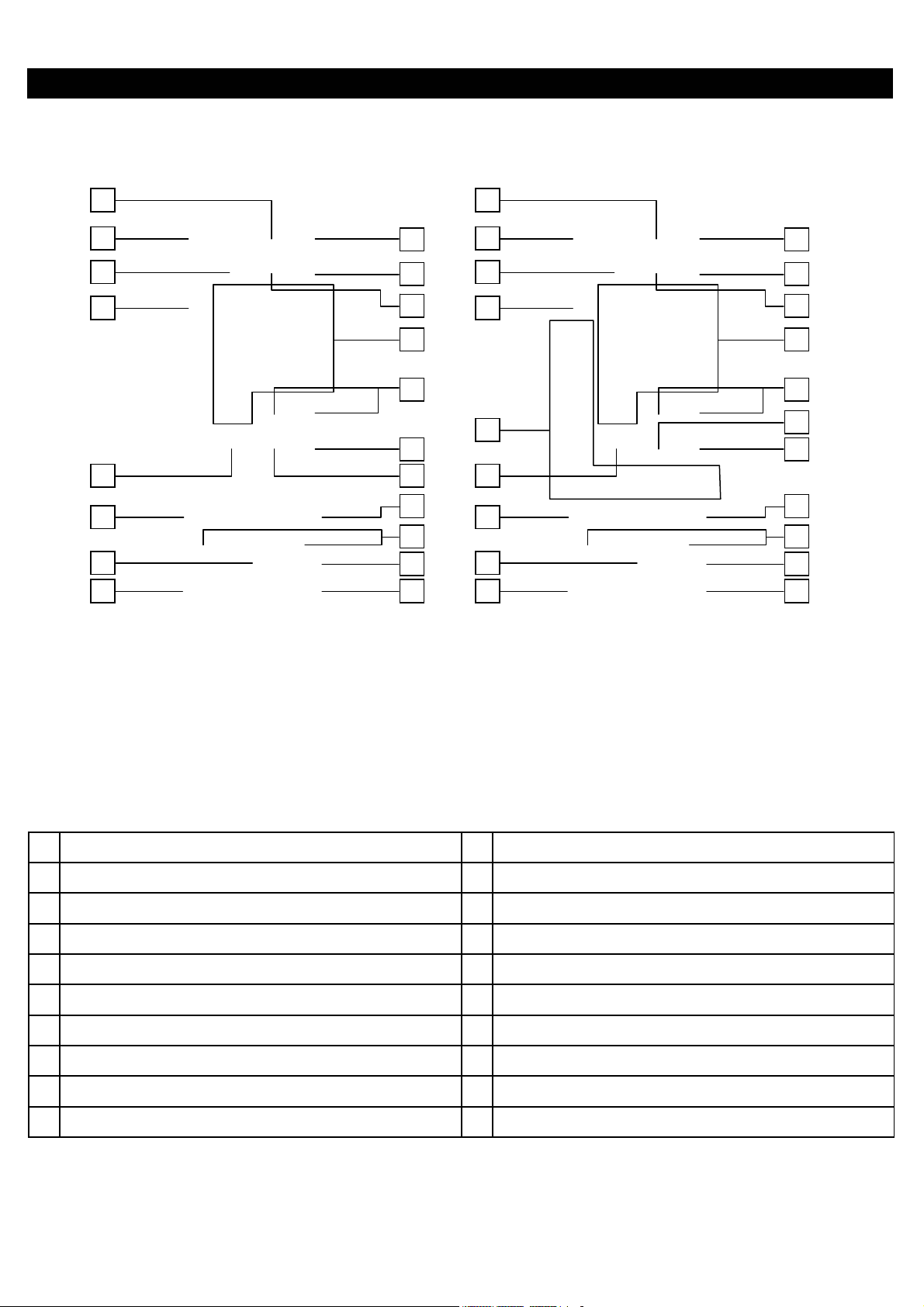
REMOTE CONTROL UNIT
19
16
10
11
2
1
6
7
5
17
18
14
4
8
9
12
3
15
13
19
16
20
10
11
2
1
6
7
5
17
18
14
4
9
8
12
3
15
13
Models without Teletext Models with Teletext
POWER ON/OFF SWITCH DEFAULT
1. 11.
2. 12.
INPUT SELECTOR MUTE
3. 13.
VOLUME UP/DOWN CHI/II (FOR NICAM/A2 MODELS)
4. 14.
PROGRAMME UP/DOWN PROGRAMME SELECTOR (DIRECT KEY)
5. 15.
RECALL CURSO
6. 16.
SURROUND SOUND RETURN
7. 17.
MENU COLOR SYSTEM
8. 18.
TIMER SOUND SYSTEM
9. 19.
PICTURE EQUALIZER
10. 20
SOUND T/TEXT FUNCTION KEY (T/TEXT MODELS ONLY)
- 3 -
Page 4

GENERAL OPERATIONS GUIDE
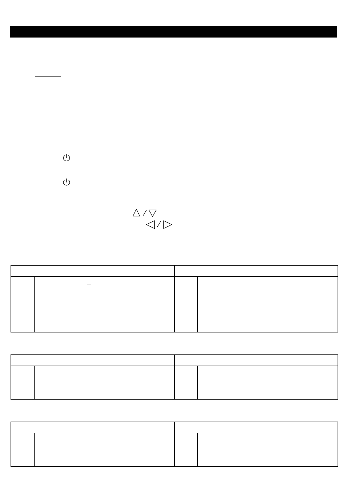
With this set, all adjustments/settings are performed by selecting from menu screens. Different menu screens and details
of adjustments/settings are shown below. To access the menu screen, press the button, then select the item by
pressing the up/down cursor buttons and adjust by the left/right cursor buttons .
MENU
- 4 -
Page 5

- 5 -
BLOCK DIAGRAM
Page 6
A
A
DJUSTMENT INSTRUCTIONS
HOW TO GO TO SERVICE MODE
1. How to go to adjustment mode no 001 ~ 022
Procedure
(1) Turn TV off by power switch on the TV set.
(2) Press " FUNCTION " button on the TV set and kept depress the button.
(3) Turn TV on by power switch on the TV set.
2. How to go to adjustment mode no 101 ~ 328
Procedure
(1) Set volume to be “0”.
(2) Press button on remote control to go to standby mode.
(3) Press “TV/VIDEO” button on the TV set, and kept depress the button.
(4) Press button on remote control to go to operation mode.
(5) TV will show service table,then please cancel to keep depress the "TV/VIDEO" button.
Note : 1. Press the UP/DOWN cursor buttons
2. Adjust data by the left/right cursor buttons .
3. Press "RECALL" buttons to restore the data.
+B ADJUSTMENT
PREPARATION PROCEDURES
1
AC input voltage 230 +
2 Turns on the set and set the brightness and contrast +B voltage : TP902
to Max.(Signal : Philips Pattern) GND : TP901
3 After 30 sec heat-run, check & adjust the +B voltage
FREE RUN FREQUENCY ADJUSTMENT
Receive a PAL-I monoscope signal on TV mode.
1
5V(50Hz)
PREPARATION PROCEDURES
to select adjustment mode no.
1
1
djust R954 to obtain +B voltage as below
Select adjustment mode no. 1 and press "MENU" button
one time.
VIF-VCO FREE RUN FREQUENCY ADJUSTMENT
PREPARATION PROCEDURES
Receive a PAL-I monoscope signal on TV mode.
1
Select adjustment mode no. 2 and press "MENU" button
1
one time.
- 6 -
Page 7
SOUND TRAP FREQUENCY ADJUSTMENT
A
PREPARATION PROCEDURES
Receive a PAL-I monoscope signal on TV mode.
1
Select adjustment mode no. 3 and press "MENU" button
1
one time.
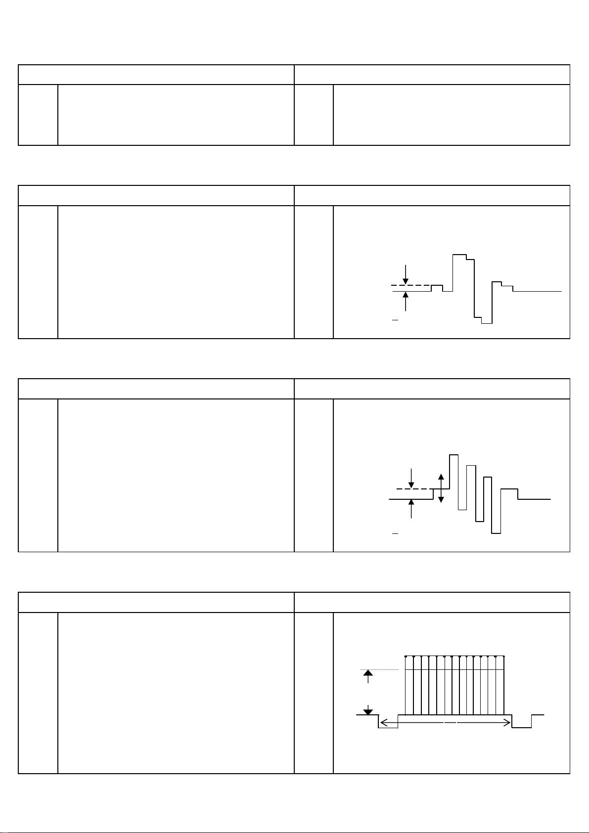
SECAM R-Y OFFSET ADJUSTMENT
PREPARATION PROCEDURES
1 Receive a secam color bar signal on Video 2. 1 Select adjustment mode no. 4.
2 Connect oscilloscope probe to pin 5 of E701. 2 Adjust output level at pin 5 of E701 as indicated below
using service mode no. 4.
0.1 V
0 +
SECAM B-Y OFFSET ADJUSTMENT
PREPARATION
1 Receive a secam color bar signal on Video 2. 1
2 Connect oscilloscope probe to pin 5 of E701. 2
Select adjustment mode no. 5.
djust output level at pin 5 of E701 as indicated below
PROCEDURES
using service mode no. 5.
0.1 V
0 +
WHITE PEAK LEVEL ADJUSTMENT
PREPARATION PROCEDURES
1 Connect oscilloscope probe to pin 3 of E202 on CPT 1 Adjust output level at pin 3 of E202 as indicated below
P.W.B with respect to ground. using service mode no. 15.
2 Input PAL cross hatch signal to Video 2 terminal.
Cross hatch signal input level : 1 Vpp + 10%(with load
A
75 ohm) or 2 Vpp + 10%(no load).
3 Set CONTRAST to MAX.
1H
4 Set data in adjustment mode no.15 to 90. A = 2.8 + 0.1Vpp
- 7 -
Page 8
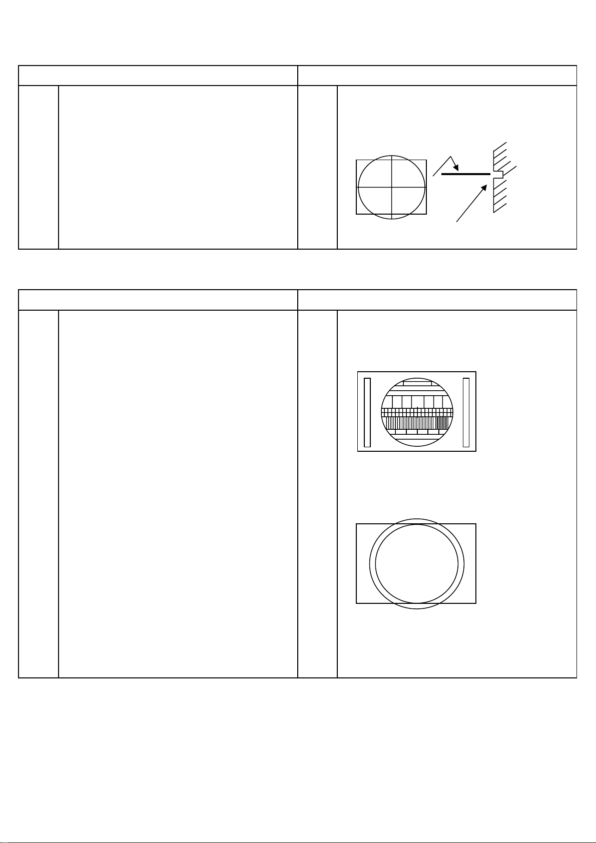
VERTICAL SHIFT ADJUSTMENT
PREPARATION PROCEDURES
1 Preheat more than 5 minutes of power supply. 1 Select the IIC control address No. 11.
2 Receive PAL Philips pattern signal. 2 Set the horizontal center line to vertical center maker
of CRT by adjustment of IIC.
Vertical center marker of CRT
VERTICAL SIZE ADJUSTMENT
PREPARATION PROCEDURES
1 Preheat more than 5 minutes of power supply. 1 Select the IIC control address No. 12.
2 Receive Philips pattern signal. 2 Adjust IIC data to obtain the following conditions.
PAL
Check vertical amplitude as below by
3
NTSC circle pattern.
NTSC
4 If picture isn't center, go back to IIC control No. 11 and
adjust IIC data to obtain the following conditions.
- 8 -
Page 9
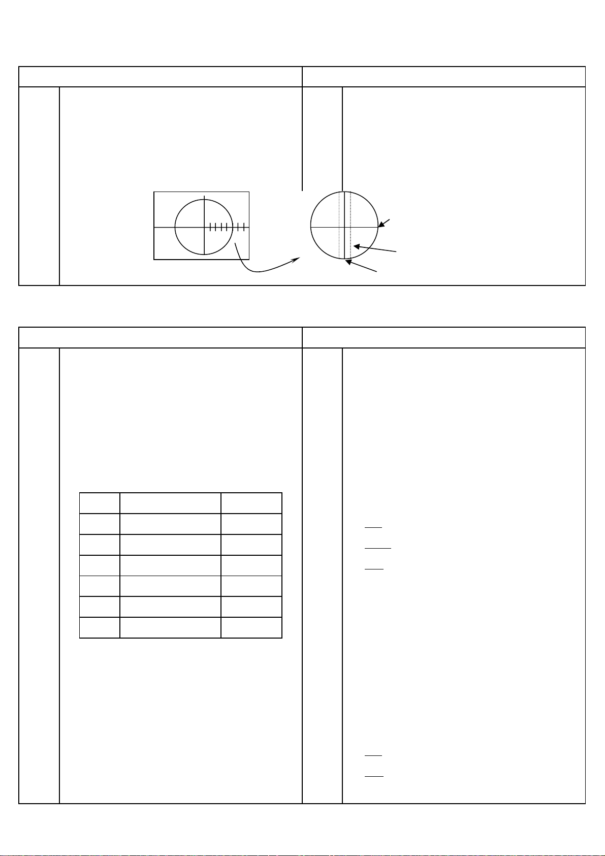
SIDE PIN DISTORTION ADJUSTMENT
PREPARATION PROCEDURES
Purity adjustment and convergence adjustment should
1
be already completed. 2
Set Contrast = 100, Brightness = 50
2
Set horizontal size adjustment to approximately 2-2 by
3
1 Receive the circle pattern signal.
st
Adjust the 1
outer vertical line (R/L) to pin, 2nd outer
vertical line (R/L) to straight using side pin adjustment
(PCC-AMP VR R557 / PCC-PHASE VR R564).
H-WIDTH VR R559. 3 Receive the cross hatch signal.
Vertical amplitude adjustment should be already
4
4 Check that the vertical line is straight, except 1st outer
completed. vertical line (R/L).
*Pin distortion spec. DL ≤ 3mm ,DR ≤ 2mm*
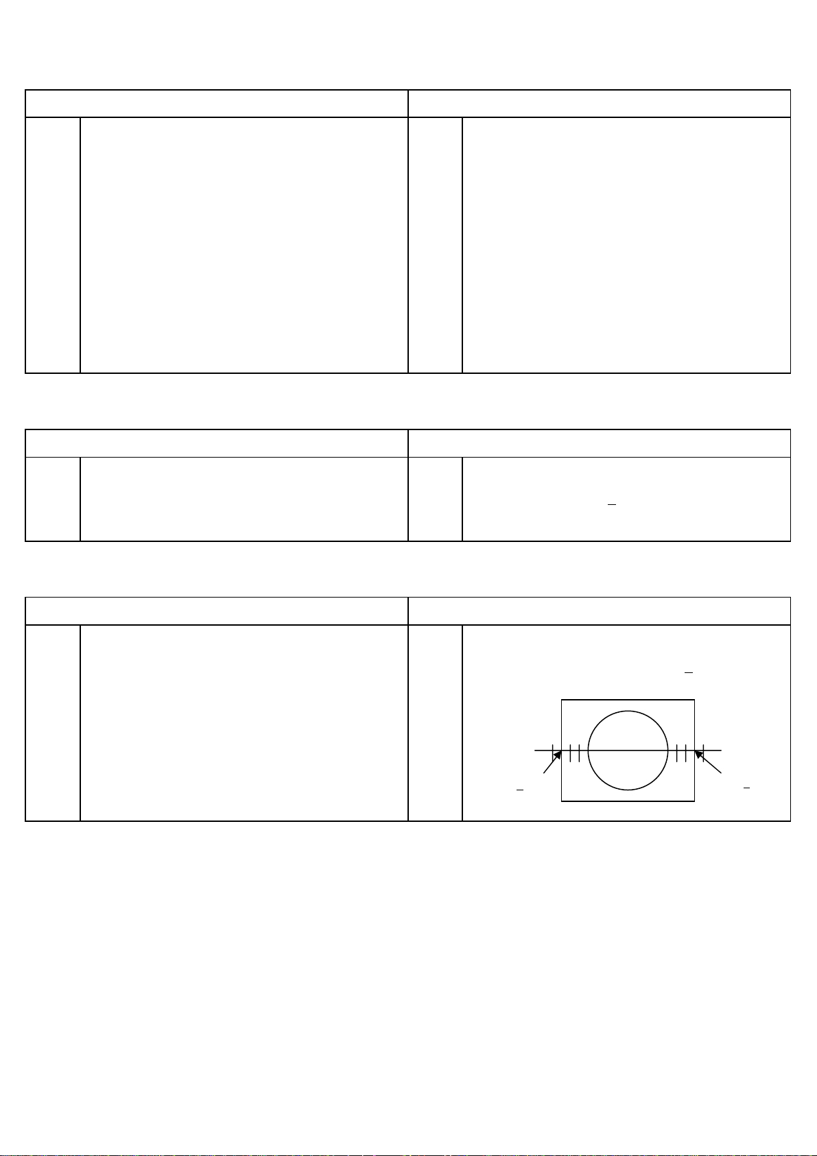
HORIZONTAL CENTER ADJUSTMENT
PREPARATION PROCEDURES
1 Side pin adjustment should be already completed. 1 Adjust adjustment mode no. 13 so that the average
2 Receive circle pattern signal. reading of R and L is 2.0 +
HORIZONTAL SIZE ADJUSTMENT
PREPARATION PROCEDURES
Horizontal center adjustment should be already
1
1 Adjust Horizontal size (H-WIDTH VR R559) so that the
completed. average reading of right and left is 2.0 +
2 Receive circle pattern signal.
3 Set Contrast = 100, Brightness = 50
2.0 + 0.5
0.5 at circle pattern signal.
0.5.
2.0 + 0.5
- 9 -
Page 10
FOCUS ADJUSTMENT
s
A
PREPARATION
PROCEDURES
1 Receive Philips pattern signal. 1 Set picture to mode 1
2 Vertical amplitude adjustment should be already 2 Turn the focus VR gradually clockwise from the full
completed. counterclockwise and adjust so that the halo of vertical
3 Adjust the cut-off after pre-adjust focus VR. center line does not appear, and horizontal line is
4 Check the cut-off in case focus is re-adjusted MIN. width.
HORIZONTAL
1 2 3 4 5 6 7
NO.5
ZOOM
HALO
VERTICAL
WHITE BALANCE ADJUSTMENT
PREPARATION
1 Adjust the W/B after the Power is turned ON for 20 minute
1 Turn the screen adjusting VR clockwise and set it to the
PROCEDURES
2 Purity adjustment should be completed. position where the bright line starts appearing on CPT
3 Set the vertical incident illumination on the CPT surface screen.
to 20 lux or less. 2 Take the first appeared color as the reference. Adjust the
4 Receive white raster signal. other colors by remote until both appear to be the same
5 Set adjustment mode data as table on the next page level as the reference. (A white horizontal line is seen at
to default.
Disp No ITEM Default
016
017
018
019
020
021
R-CUTOFF
G-CUTOFF
B-CUTOFF
R-DRIVE
B-DRIVE
SUB-BRIGHT
127
127
127
63
63
127
6 Turn the screen adjustment VR fully counterclockwise. 5
7 Set to lateral line mode by Press “MUTE” button on
the CPT center.)
Low brightness adjustment data
Red
Green
Blue
………. ”1” key for up, “4” key for down.
………. ”2” key for up, “5” key for down.
………. ”3” key for up, “6” key for down
Don’t change the data of the reference color
3 Exit the lateral line mode. (Press “MUTE” by remote).
4 Set white balance meter at the center of the screen.
djust brightness control so that the indication of the
brightness meter is a prescribed value of brightness
remote control . adjustment. Adjust white balance with the white balance
control data (Red/Blue).
High brightness adjustment data
Red
Blue
………. ”7” key for up, “0” key for down.
………. ”8” key for up, “9” key for down.
- 10 -
Page 11
SUB-BRIGHTNESS ADJUSTMENT
A
A
PREPARATION PROCEDURES
1 Turn the TV set on and heat run for 20 minutes or more. 1 Press "PICTURE" key until go to picture mode 2.
2 Horizontal size adjustment and side pin adjustment 2 The sub-brightness should be adjusted (Adjustment
should be completed. mode no. 21) using11 steps gray scale (A1-A1) of color
3 Receive Philips pattern signal. bar pattern
Set picture mode 2 as shown below. 3 Adjust until A10 is complete black and A9 is lightly black.
4 Go out from service mode.
CONTRAST : 0
COLOR : 0
BRIGHTNESS : 50
A
11
A10A
A8A7A6A5A4A3A2A
9
1
5 Adjust picture mode 2 as below.
CONTRAST : 100
COLOR : 60
BRIGHTNESS : 50
6 Press "PICTURE" key until go to picture mode 1.
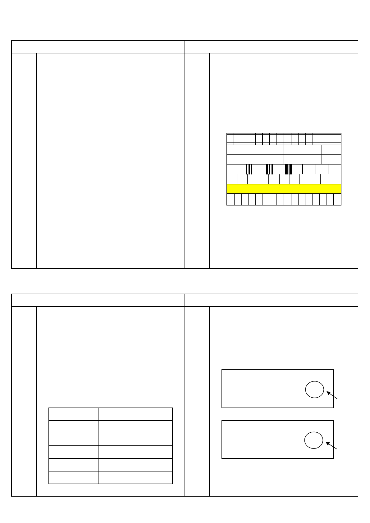
AGC ADJUSTMENT
PREPARATION PROCEDURES
1 All adjustment except for AGC adjustment should be 1 Select adjustment mode no. 14 (TUNER AGC) and press
completed. Heat-run for more than 5 min. “MENU” key one time. Data will be adjusted automatically
2 Receive signal as table on the next page. 2 .When AGC adjustment is complete,screen should be
3 Set Contrast = 100, Brightness = 50. shown "OK" on the right-top side. It the screen show
4 Set the Sound System and Color System depending on "NG" ,it means AGC adjustment is abnormal.
the broadcast system.
5 Set the antenna input level as specified below.
NO.
014 43 OK
DJUSTMENT 10
"OK"
MODEL T1
DESTINATION ALL
BGSYSTEM
CHANNEL CH10
INPUT SIGNAL Philips Pattern
INPUT LEVEL - 54 dBm / 55dBµ(75Ω)
NO.
014 15 NG
Caution : After AGC adjustment is complete, data in
adjustmentment mode no. 14 should be more than 30.
DJUSTMENT 10
"NG"
If not, please re-check or/and adjust again.
- 11 -
Page 12

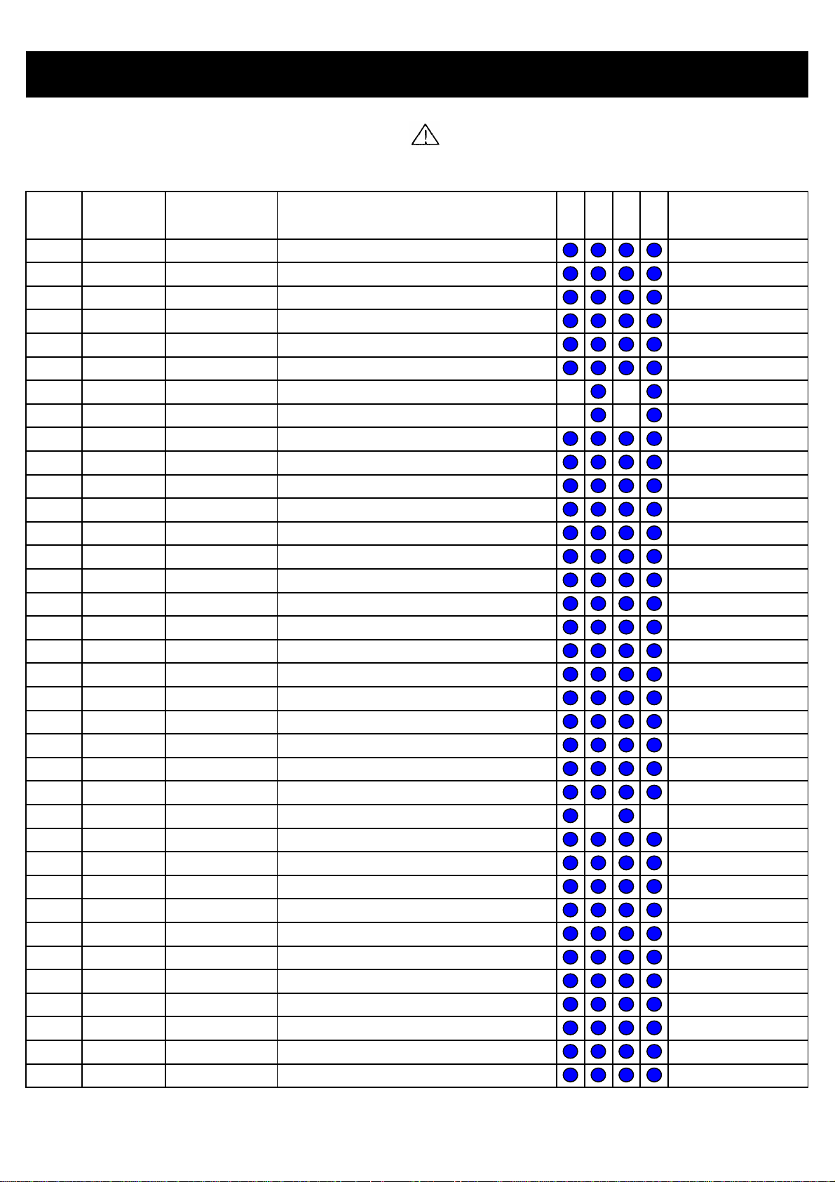
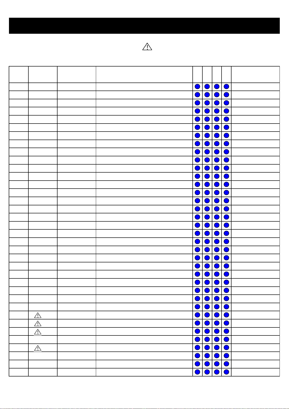
REPLACEMENT PARTS LIST
O
PRODUCT SAFETY NOTE : Components marked with a have special characteristics important to safety. Before
replacing any of these components, read carefully the PRODUCT SAFETY NOTICE of this Service Manual. Don't degrade
the safety of the receiver through improper servicing
NO CCT NO.
1
2
3
4
5
6
7
8
9
10
11
12
13
14
15
16
17
18
19
20
21
22
23
24
25
26
27
28
29
30
31
32
33
34
35
36
#I904
#I501
#Q502
#I901
#Q503
#D902
C101
C102
C103
C107
C108
C201
C202
C203
C206
C207
C208
C209
C210
C211
C212
C213
C214
C215
C216
C217
C218
C219
C220
C221
C222
C223
C224
C225
C226
C227
HITACHI HITACHI
PARTS NO. DESCRIPTION
THS0401001P
THS0402001P
THS0403001P
THS0404002P
THS0405001P
THS0405002P
0800358R
CE-1TZ103
0800294R
0800303R
0890092R
0800352R
CE-1TZ104
CE-1TZ104
CE-1TZ103
CE-1TCHJ181
CE-1TZ103
0800352R
0800279R
CE-1TZ103
0800279R
0800279R
0880183R
CE-1TCHJ221
CE-1TZ104
0800352R
0800317R
EL-B10V471R
0800362F
0890092R
0800279R
0890065R
0800277R
0880198R
0880198R
CE-1TZ104
HEAT SINK I904 / I905
HEAT SINK I501
HEAT SINK Q502
HEAT SINK I901 ( L = 60mm )
HEAT SINK Q503 ( L = 40mm )
HEAT SINK D902 ( L = 25mm )
CAP ELEC 1000UF 6.3V M
CAP CER 0.01UF 50V Z
CAP ELEC 10UF 50V M
CAP ELEC 22UF 50V M
CAP CER 2200PF 50V M
CAP ELEC 470UF 10V M
CAP CER 0.1UF 50V Z
CAP CER 0.1UF 50V Z
CAP CER 0.01UF 50V Z
CAP CER 180PF 50V J CH
CAP CER 0.01UF 50V Z
CAP ELEC 470UF 10V M
CAP ELEC 1UF 50V M
CAP CER 0.01UF 50V Z
CAP ELEC 1UF 50V M
CAP ELEC 1UF 50V M
CAP POLYESTER 0.015UF 50V J
CAP CER 220PF 50V J CH
CAP CER 0.1UF 50V Z
CAP ELEC 470UF 10V M
CAP ELEC 47UF 16V M
CAP ELEC 470UF 10V M 105
CAP ELEC 1000UF 25V M
CAP CER 2200PF 50V M
CAP ELEC 1UF 50V M
CAP CER 22PF 50V J SL
CAP ELEC 0.47UF 50V M
CAP POLYESTER 0.22UF 50V J
CAP POLYESTER 0.22UF 50V J
CAP CER 0.1UF 50V Z
SN ST SNT S
REMARK
C
- 12 -
Page 13
REPLACEMENT PARTS LIST
O
O
PRODUCT SAFETY NOTE : Components marked with a have special characteristics important to safety. Before
replacing any of these components, read carefully the PRODUCT SAFETY NOTICE of this Service Manual. Don't degrade
the safety of the receiver through improper servicing
NO CCT NO.
37
38
39
40
41
42
43
44
45
46
47
48
49
50
51
52
53
54
55
56
57
58
59
60
61
62
63
64
65
66
67
68
69
70
71
72
C228
C229
C232
C233
C234
C236
C237
C238
C239
C241
C242
C243
C244
C245
C247
C248
C249
C250
C251
C252
C253
C255
C256
C257
C258
C401
C402
C403
C404
C405
C406
C407
C408
C409
C410
C411
HITACHI HITACHI
PARTS NO. DESCRIPTION
0880198R
0880181R
0890093R
0880194R
0800279R
CE-1TZ103
0890074R
0890074R
AL00002R
0800279R
0880207R
CE-1TZ103
CE-1TZ103
0800326R
0800279R
0880184R
CE-1TZ103
0800326R
EL-B16V101R
0800294R
EL-B50V100R
0800326R
CE-1TZ103
CE-1TZ103
CE-1TCHJ181
0800326R
0800277R
0800277R
0800294R
CE-1TZ103
0800294R
0800277R
0800277R
CE-1TZ103
0800294R
0800294R
CAP POLYESTER 0.22UF 50V J
CAP POLYESTER 0.01UF 50V J
CAP CER 2700PF 50V M
CAP POLYESTER 0.1UF 50V J
CAP ELEC 1UF 50V M
CAP CER 0.01UF 50V Z
CAP CER 100PF 50V J SL
CAP CER 100PF 50V J SL
CAP ELEC 1UF 160V M
CAP ELEC 1UF 50V M
CAP POLYESTER 1UF 50V J
CAP CER 0.01UF 50V Z
CAP CER 0.01UF 50V Z
CAP ELEC 100UF 16V M
CAP ELEC 1UF 50V M
CAP POLYESTER 0.018UF 50V J
CAP CER 0.01UF 50V Z
CAP ELEC 100UF 16V M
CAP ELEC 100UF 16V M 105
CAP ELEC 10UF 50V M
CAP ELEC 10UF 50V M 105
CAP ELEC 100UF 16V M
CAP CER 0.01UF 50V Z
CAP CER 0.01UF 50V Z
CAP CER 180PF 50V J CH
CAP ELEC 100UF 16V M
CAP ELEC 0.47UF 50V M
CAP ELEC 0.47UF 50V M
CAP ELEC 10UF 50V M
CAP CER 0.01UF 50V Z
CAP ELEC 10UF 50V M
CAP ELEC 0.47UF 50V M
CAP ELEC 0.47UF 50V M
CAP CER 0.01UF 50V Z
CAP ELEC 10UF 50V M
CAP ELEC 10UF 50V M
SN ST SNT S
REMARK
C
C
- 13 -
Page 14
REPLACEMENT PARTS LIST
O
PRODUCT SAFETY NOTE : Components marked with a have special characteristics important to safety. Before
replacing any of these components, read carefully the PRODUCT SAFETY NOTICE of this Service Manual. Don't degrade
the safety of the receiver through improper servicing
NO CCT NO.
73
74
75
76
77
78
79
80
81
82
83
84
85
86
87
88
89
90
91
92
93
94
95
96
97
98
99
100
101
102
103
104
105
106
107
108
C412
C413
C414
C415
C416
C417
C418
C431
C432
C433
C436
C437
C451
C501
C501A
C502
C504
C505
C506
C507
C509
C510
C511
C515
C516
C517
C518
C519
C520
C521
C522
C524
C525
C526
C527
C701
HITACHI HITACHI
PARTS NO. DESCRIPTION
0800277R
0800294R
0800294R
0800294R
0800277R
CE-1TZ103
0800352R
0800294R
0800294R
0800294R
0800294R
0800294R
0800277R
0279693R
0279693R
0800328R
0800368F
0880209R
0800355R
0800354R
AL00028R
0880204R
0800355R
0299622F
0284642R
0243510R
0243503R
EL-B160V010R
0262427F
0299987F
0262423F
CM-50V3U3J
AN01177F
0890074R
0279690R
0800315R
CAP ELEC 0.47UF 50V M
CAP ELEC 10UF 50V M
CAP ELEC 10UF 50V M
CAP ELEC 10UF 50V M
CAP ELEC 0.47UF 50V M
CAP CER 0.01UF 50V Z
CAP ELEC 470UF 10V M
CAP ELEC 10UF 50V M
CAP ELEC 10UF 50V M
CAP ELEC 10UF 50V M
CAP ELEC 10UF 50V M
CAP ELEC 10UF 50V M
CAP ELEC 0.47UF 50V M
CAP POLY FILM 0.1UF 100V K
CAP POLY FILM 0.1UF 100V K
CAP ELEC 100UF 35V M
CAP ELEC 2200UF 25V M
CAP POLYESTER 1.5UF 50V J
CAP ELEC 470UF 35V M
CAP ELEC 470UF 25V M
CAP ELEC 10UF 250V M
CAP POLYESTER 0.56UF 50V J
CAP ELEC 470UF 35V M
CAP POLYPROPY 0.01UF 630V J
CAP ELEC 50V 10 UF (NP)
CAP CER 560PF 500V K
CAP CER 150PF 500V K
CAP ELEC 1UF 160V M 105
CAP M-POLYPRO 0.01UF J 1.8KHP
CAP POLYPRO 0.039UF J 630V
CAP M-POLYPRO 6800PF J 1.8KHP
CAP POLYESTER 3.3UF 50V J
CAP M-POLYPRO 0.43UF J 250V
CAP CER 100PF 50V J
CAP POLYESTER 0.033UF 100V K
CAP ELEC 47UF 6.3V
SN ST SNT S
REMARK
C
- 14 -
Page 15

REPLACEMENT PARTS LIST
o
o
o
o
o
o
PRODUCT SAFETY NOTE : Components marked with a have special characteristics important to safety. Before
replacing any of these components, read carefully the PRODUCT SAFETY NOTICE of this Service Manual. Don't degrade
the safety of the receiver through improper servicing
NO CCT NO.
109
110
111
112
113
114
115
116
117
118
119
120
121
122
123
124
125
126
127
128
129
130
131
132
133
134
135
136
137
138
139
140
141
142
143
144
C701A
C702
C703
C704
C705
C711
C712
C713
C714
C716
C902
C903
C904
C905
C906
C907
C908
C909
C910
C911
C912
C913
C914
C915
C916
C917
C919
C921
C923
C924
C924
C928
C929
C930
C931
C932
HITACHI HITACHI
PARTS NO. DESCRIPTION
0880057R
0800326R
CE-1TZ103
0890083R
CE-1TZ103
CE-1TZ103
CE-1TZ103
0800326R
0890087R
0800294R
0880035R
EL-B35V470R
0880038R
EL-B50V010R
0880038R
EL-B50V010R
EL-B50V100R
CE-1TZ104
EL-B25V222R
0880194R
0880194R
0880194R
0880194R
EL-B25V102R
AL01663
0800294R
AJ00542F
0890087R
CE-1TCHJ181
0800348R
CE-1TZ104
AJ00454F
0890083R
0800294R
AL01702
AN02083S
CAP POLYESTER 0.1UF 50V K
CAP ELEC 100UF 16V M
CAP CER 0.01UF 50V Z
CAP CER 470PF 50V K
CAP CER 0.01UF 50V Z
CAP CER 0.01UF 50V Z
CAP CER 0.01UF 50V Z
CAP ELEC 100UF 16V M
CAP CER 1000PF 50V K
CAP ELEC 10UF 50V M
CAP POLYESTER 2200PF 50V K
CAP ELEC 47UF 35V M 105
CAP POLYESTER 3900PF 50V K
CAP ELEC 1UF 50V M 105
CAP POLYESTER 3900PF 50V K
CAP ELEC 1UF 50V M 105
CAP ELEC 10UF 50V M 105
CAP CER 0.1UF 50V Z
CAP ELEC 2200UF 25V M 105
CAP POLYESTER 0.1UF 50V J
CAP POLYESTER 0.1UF 50V J
CAP POLYESTER 0.1UF 50V J
CAP POLYESTER 0.1UF 50V J
CAP ELEC 1000UF 25V M 105
CAP ELEC 330UF 160V M
CAP ELEC 10UF 50V M
CAP CER 4700PF 1KV K
CAP CER 1000PF 50V K
CAP CER 180PF 50V J CH
CAP ELEC 330UF 63V M
CAP CER 0.1UF 50V Z
CAP CER 1000PF 1KV K
CAP CER 470PF 50V K
CAP ELEC 10UF 50V M
CAP ELEC 220UF 450V M
CAP M-POLYPRO X2 0.1UF K 250V
SN ST SNT S
REMARK
C
C
C
C
C
C
Code 433, 435 only
- 15 -
Page 16

REPLACEMENT PARTS LIST
PRODUCT SAFETY NOTE : Components marked with a have special characteristics important to safety. Before
replacing any of these components, read carefully the PRODUCT SAFETY NOTICE of this Service Manual. Don't degrade
the safety of the receiver through improper servicing
NO CCT NO.
145
146
147
148
149
150
151
152
153
154
155
156
157
158
159
160
161
162
163
164
165
166
167
168
169
170
171
172
173
174
175
176
177
178
179
180
C933
C934
C935
CT001
D101
D203
D204
D205
D206
D207
D208
D209
D210
D211
D212
D213
D214
D214A
D215
D215A
D216
D216A
D219
D220
D501
D502
D503
D504
D505
D506
D507
D508
D509
D510
D511
D703
HITACHI HITACHI
PARTS NO. DESCRIPTION
AN02083S
AJ00539F
AJ00824
0880045R
2339971M
2338321M
2338321M
2339887M
2339862M
2338321M
DS-0004AAM
2338321M
2338321M
2338321M
DS-0004AAM
2339837M
2338321M
2338321M
2338321M
2338321M
2338321M
2338321M
2338321M
2339862M
DS-0004AAM
DS-0004AAM
DS-0004AAM
2339887M
2338321M
DS-0004AAM
DS-0003AAM
DS-0001AAM
DS-0004AAM
DS-0004AAM
DS-0004AAM
2339853M
CAP M-POLYPRO X2 0.1UF K 250V
CAP CER 2200PF 1KV K
CAP CER 3300PF 250V M
CAP POLYESTER 0.012UF 50V K
DI HZS33-1
DI 1SS270
DI 1SS270
DI HZS12C1
DI HZS9A2
DI 1SS270
DI EU2A(V1)
DI 1SS270
DI 1SS270
DI 1SS270
DI EU2A(V1)
DI HZS5C1
DI 1SS270
DI 1SS270
DI 1SS270
DI 1SS270
DI 1SS270
DI 1SS270
DI 1SS270
DI HZS9A2
DI EU2A(V1)
DI EU2A(V1)
DI EU2A(V1)
DI HZS12C1
DI 1SS270
DI EU2A(V1)
DI RS-4FS
DI RU4AM
DI EU2A(V1)
DI EU2A(V1)
DI EU2A(V1)
DI HZS7A3
SN ST SNT S
REMARK
- 16 -
Page 17

REPLACEMENT PARTS LIST
A
A
A
R
R
PRODUCT SAFETY NOTE : Components marked with a have special characteristics important to safety. Before
replacing any of these components, read carefully the PRODUCT SAFETY NOTICE of this Service Manual. Don't degrade
the safety of the receiver through improper servicing
NO CCT NO.
181
182
183
184
185
186
187
188
189
190
191
192
193
194
195
196
197
198
199
200
201
202
203
204
205
206
207
208
209
210
211
212
213
214
215
216
D704
D705
D706
D707
D901
D902
D903
D904
D905
D906
D907
D908
D910
D911
D912
DC701
DI905
DT001
E202
E401
E402
E403
E405
E502
E503
E505
E701
E702
E703
E901
E902
E903
E904
F903
F904
FK230
HITACHI HITACHI
PARTS NO. DESCRIPTION
2339837M
2339971M
2339858M
2339858M
DS-0004AAM
DS-0001AA2
DS-0001AAM
2338321M
2338321M
DS-0004AAM
DS-0004AAM
2339911M
2339841M
2338321M
DS-0001ANM
2339858M
2343161M
2338321M
1EF2035
JP-09P01AB
EY01161
TWI4004302P
JP-03P02AB
1EF2024
ED03659
TWI4003702
2902264
TWI4003604P
2902261TA
2902263
XXX
TWI4004102P
ED03174
AZ00898M
AZ00101
AZ00105
DI HZS5C1
DI HZS33-1
DI HZS7C2
DI HZS7C2
DI EU2A(V1)
DI FMB-G16L
DI RU4AM
DI 1SS270
DI 1SS270
DI EU2A(V1)
DI EU2A(V1)
DI HZS18-1
DI HZS6A1
DI 1SS270
DI D3SBA60-7100
DI HZS7C2
DI HZS36-1L
DI 1SS270
6P CONN W/WIRE
JACK 9P YKC21-4690N
JACK S-VIDEO YKF51-5503N
6PIN CONNECTOR PLUG
JACK 3P YKC21-4399N
BOARD-IN-CONNECTO
4P WITH BASE (VOID 2 PIN)
CONNECTOR PLUG (L=490mm)
5PIN CONNECTOR PLUG
2PCON WITH WIRE (L=520mm)
2P CONNECTOR
4P WITH BASE
AC CORD
CONNECTO
4P WITH BASE
MICRO FUSE 5
MICRO FUSE 0.5
MICRO FUSE 2.5
SN ST SNT S
REMARK
SEE APPENDIX I
- 17 -
Page 18

REPLACEMENT PARTS LIST
K
K
K
K
K
K
PRODUCT SAFETY NOTE : Components marked with a have special characteristics important to safety. Before
replacing any of these components, read carefully the PRODUCT SAFETY NOTICE of this Service Manual. Don't degrade
the safety of the receiver through improper servicing
NO CCT NO.
217
218
219
220
221
222
223
224
225
226
227
228
229
230
231
232
233
234
235
236
237
238
239
240
241
242
243
244
245
246
247
248
249
250
251
252
I201
I401
I501
I701
I702
I901
I902
I903
I904
L101
L102
L104
L201
L203
L501
L502
L503
L901
L902
L903
Q101
Q201
Q202
Q203
Q204
Q205
Q206
Q207
Q401
Q501
Q502
Q503
Q504
Q701
Q702
Q703
HITACHI HITACHI
PARTS NO. DESCRIPTION
IC-0001AC1
IC-0002AC1
IC-0002AD2
IC-0002AE0
XXX
IC-0003AD3
IC-0001AA2
CP08261U
IC-0002AA2
2123412M
2122253M
2122253M
2123109M
2123103M
2124183
LF-T332J
LH-0001AR
BH01162M
BZ02124
BZ02124
TB-0002ACR
TB-0001ACR
TB-0001AFR
TB-0002ACR
TB-0003ACR
TB-0003ACR
TB-0005AFR
TB-0001AFR
TB-0003ACR
CF01061R
CF02521
2312174
CF01431R
TB-0003ACR
TB-0001AFR
TB-0003ACR
IC M61262BFP
IC M52791FP
IC LA78041
IC M24C08-WBN6G
IC M37160M8
IC LA42152
IC SE130N
OPTOCOUPLERS H11A817B300W
IC STR-F6656
COIL AXIAL 1.2UH
COIL AXIAL 100UH
COIL AXIAL 100UH
COIL AXIAL 33UH
COIL AXIAL 10UH
COIL CHOKE 500UH
COIL FILTER 3300UH J
LINEARITY COIL ELH5L436163
FERRITE BEAD WITH CORE 2.3UH
LINE FILTER ELF24V020AM
LINE FILTER ELF24V020AM
TRS 2SC1906
TRS 2SA1993-E,F
TRS 2SC2236-O,Y
TRS 2SC1906
TRS 2SC5395-E,F
TRS 2SC5395-E,F
TRS 2SC5171(LBS4MBS-K)(Lead straight)
TRS 2SC2236-O,Y
TRS 2SC5395-E,F
TRS MPSA42
TRS 2SD2581-RF
TRS 2SD2375-P
TRS KTA1266
TRS 2SC5395-E,F
TRS 2SC2236-O,Y
TRS 2SC5395-E,F
SN ST SNT S
REMARK
SEE APPENDIX II
Code 433, 435 only
- 18 -
Page 19

REPLACEMENT PARTS LIST
PRODUCT SAFETY NOTE : Components marked with a have special characteristics important to safety. Before
replacing any of these components, read carefully the PRODUCT SAFETY NOTICE of this Service Manual. Don't degrade
the safety of the receiver through improper servicing
NO CCT NO.
253
254
255
256
257
258
259
260
261
262
263
264
265
266
267
268
269
270
271
272
273
274
275
276
277
278
279
280
281
282
283
284
285
286
287
288
Q901
QT001
R102
R103
R104
R105
R106
R108
R109
R110
R111
R201
R202
R203
R204
R208
R209
R210
R211
R212
R213
R214
R215
R216
R217
R219
R220
R221
R222
R223
R224
R226
R228
R230
R232
R233
HITACHI HITACHI
PARTS NO. DESCRIPTION
TB-0003ACR
2320637M
0700027M
0700049M
0700037M
0700059M
0700049M
0700027M
0700027M
0700043M
0700018M
0187038M
0187038M
0700027M
0700027M
0700052M
0700063M
0700063M
0700045M
0700058M
0700058M
0700027M
0700054M
RM-W01F561JA
AT00318S
0700034M
0700047M
0700041M
0700038M
0700045M
0700041M
0700034M
AT03694M
0700058M
0700081M
0700027M
TRS 2SC5395-E,F
TRS 2SA673 C/D
RES CAR 1/16W 100R J
RES CAR 1/16W 4.7K J
RES CAR 1/16W 560R J
RES CAR 1/16W 27K J
RES CAR 1/16W 4.7K J
RES CAR 1/16W 100R J
RES CAR 1/16W 100R J
RES CAR 1/16W 1.5K J
RES CAR 1/16W 22R J
RES CAR 1/16W 75R J
RES CAR 1/16W 75R J
RES CAR 1/16W 100R J
RES CAR 1/16W 100R J
RES CAR 1/16W 6.8K J
RES CAR 1/16W 47K J
RES CAR 1/16W 47K J
RES CAR 1/16W 2.2K J
RES CAR 1/16W 22K J
RES CAR 1/16W 22K J
RES CAR 1/16W 100R J
RES CAR 1/16W 10K J
RES MTL OXIDE 1W 560R J
RES MTL OXIDE ERG3F 330H J
RES CAR 1/16W 330RJ
RES CAR 1/16W 3.3K J
RES CAR 1/16W 1K J
RES CAR 1/16W 680R J
RES CAR 1/16W 2.2K J
RES CAR 1/16W 1K J
RES CAR 1/16W 330R J
RES SURGE 1/2W 10M
RES CAR 1/16W 22K J
RES CAR 1/16W 1M J
RES CAR 1/16W 100R J
SN ST SNT S
REMARK
- 19 -
Page 20

REPLACEMENT PARTS LIST
PRODUCT SAFETY NOTE : Components marked with a have special characteristics important to safety. Before
replacing any of these components, read carefully the PRODUCT SAFETY NOTICE of this Service Manual. Don't degrade
the safety of the receiver through improper servicing
NO CCT NO.
289
290
291
292
293
294
295
296
297
298
299
300
301
302
303
304
305
306
307
308
309
310
311
312
313
314
315
316
317
318
319
320
321
322
323
324
R234
R237
R238
R239
R240
R241
R242
R243
R244
R245
R246
R247
R248
R249
R250
R251
R252
R253
R254
R255
R256
R257
R258
R259
R260
R261
R275
R276
R277
R401
R402
R403
R404
R405
R406
R407
HITACHI HITACHI
PARTS NO. DESCRIPTION
0700027M
0700027M
RM-W01F472JA
RM-S25U153FA
0700064M
RM-S25U153FA
RM-S25U333FA
0700059M
0700052M
AT03884M
0700054M
0700054M
0700068M
0700045M
0700045M
0700045M
0700045M
0700054M
0700027M
0700027M
0700041M
AT00321S
AT00316S
0700027M
0700027M
0700027M
0700027M
0700039M
0700032M
0700067M
0187038M
0187038M
0700067M
0187038M
0700067M
0187038M
RES CAR 1/16W 100R J
RES CAR 1/16W 100R J
RES MTL OXIDE 1W 4.7K J
RES MTL OXIDE 1/16W 15K-F
RES CAR 1/16W 56K J
RES MTL OXIDE 1/16W 15K-F
RES MTL OXIDE 1/16W 33K-F
RES CAR 1/16W 27K J
RES CAR 1/16W 6.8K J
RES CAR 1/2W 10K J
RES CAR 1/16W 10K J
RES CAR 1/16W 10K J
RES CAR 1/16W 120K J
RES CAR 1/16W 2.2K J
RES CAR 1/16W 2.2K J
RES CAR 1/16W 2.2K J
RES CAR 1/16W 2.2K J
RES CAR 1/16W 10K J
RES CAR 1/16W 100R J
RES CAR 1/16W 100R J
RES CAR 1/16W 1K J
RES MTL OXIDE ERG3F 390H J
RES MTL OXIDE ERG3F 270H J
RES CAR 1/16W 100R J
RES CAR 1/16W 100R J
RES CAR 1/16W 100R J
RES CAR 1/16W 100R J
RES CAR 1/16W 820R J
RES CAR 1/16W 220R J
RES CAR 1/16W 100K J
RES CAR 1/16W 75R J
RES CAR 1/16W 75R J
RES CAR 1/16W 100K J
RES CAR 1/16W 75R J
RES CAR 1/16W 100K J
RES CAR 1/16W 75R J
SN ST SNT S
REMARK
- 20 -
Page 21

REPLACEMENT PARTS LIST
PRODUCT SAFETY NOTE : Components marked with a have special characteristics important to safety. Before
replacing any of these components, read carefully the PRODUCT SAFETY NOTICE of this Service Manual. Don't degrade
the safety of the receiver through improper servicing
NO CCT NO.
325
326
327
328
329
330
331
332
333
334
335
336
337
338
339
340
341
342
343
344
345
346
347
348
349
350
351
352
353
354
355
356
357
358
359
360
R408
R409
R410
R411
R412
R413
R414
R415
R416
R417
R418
R419
R428
R429
R430
R431
R432
R433
R434
R435
R436
R437
R438
R451
R452
R453
R454
R455
R456
R501
R503
R505
R506
R506A
R507
R508
HITACHI HITACHI
PARTS NO. DESCRIPTION
0187038M
0700027M
0700027M
0700041M
0700027M
0700041M
0700027M
0700027M
0700027M
0700027M
AT03861M
0700025M
0700067M
0700067M
0700041M
0700041M
0700054M
0700067M
0700067M
0700027M
0700027M
0700041M
0700041M
0700067M
0187038M
0700067M
0700041M
0700027M
0700041M
0700036M
AT03897M
0188097M
0700053M
0700041M
RF-S25F2R2JA
0188096M
RES CAR 1/16W 75R J
RES CAR 1/16W 100R J
RES CAR 1/16W 100R J
RES CAR 1/16W 1K J
RES CAR 1/16W 100R J
RES CAR 1/16W 1K J
RES CAR 1/16W 100R J
RES CAR 1/16W 100R J
RES CAR 1/16W 100R J
RES CAR 1/16W 100R J
RES CAR 1/2W 180R J
RES CAR 1/16W 68R J
RES CAR 1/16W 100K J
RES CAR 1/16W 100K J
RES CAR 1/16W 1K J
RES CAR 1/16W 1K J
RES CAR 1/16W 10K J
RES CAR 1/16W 100K J
RES CAR 1/16W 100K J
RES CAR 1/16W 100R J
RES CAR 1/16W 100R J
RES CAR 1/16W 1K J
RES CAR 1/16W 1K J
RES CAR 1/16W 100K J
RES CAR 1/16W 75R J
RES CAR 1/16W 100K J
RES CAR 1/16W 1K J
RES CAR 1/16W 100R J
RES CAR 1/16W 1K J
RES CAR 1/16W 470R J
RES CAR 1/2W 100K J
RES CAR 1/2W 3.3R J
RES CAR 1/16W 8.2K J
RES CAR 1/16W 1K J
RES FUSE 1/4W 2.2R J
RES CAR 1/2W 2.7R J
SN ST SNT S
REMARK
- 21 -
Page 22

REPLACEMENT PARTS LIST
A
PRODUCT SAFETY NOTE : Components marked with a have special characteristics important to safety. Before
replacing any of these components, read carefully the PRODUCT SAFETY NOTICE of this Service Manual. Don't degrade
the safety of the receiver through improper servicing
NO CCT NO.
361
362
363
364
365
366
367
368
369
370
371
372
373
374
375
376
377
378
379
380
381
382
383
384
385
386
387
388
389
390
391
392
393
394
395
396
R509
R510
R511
R512
R513
R514
R515
R517
R518
R519
R520
R521
R522
R523
R524
R525
R526
R527
R528
R529
R701
R708
R709
R710
R711
R713
R714
R717
R718
R719
R720
R721
R722
R723
R725
R727
HITACHI HITACHI
PARTS NO. DESCRIPTION
0700055M
0700058M
RM-W03F1R2JA
RM-W03F1R2JA
RM-W03F1R2JA
0188093M
AZ00892M
0700033M
0700027M
AT00381S
0700051M
AT00381S
0700026M
RM-W03F471JA
RM-W03F4R7JA
0700027M
0700063M
0110243S
AT03861M
0100129M
0700041M
0700036M
0700027M
0700027M
0700027M
0700052M
0700052M
0700058M
0700054M
0700054M
0700058M
0700058M
0700041M
0700027M
0700027M
0700052M
RES CAR 1/16W 12K J
RES CAR 1/16W 22K J
RES MTL OXIDE 3W 1.2R J
RES MTL OXIDE 3W 1.2R J
RES MTL OXIDE 3W 1.2R J
RES CAR 1/2W 1.5R J
MICRO FUSE 1
RES CAR 1/16W 270R J
RES CAR 1/16W 100R J
RES MTL OXIDE ERG3F 682H J
RES CAR 1/16W 5.6K J
RES MTL OXIDE ERG3F 682H J
RES CAR 1/16W 82R J
RES MTL OXIDE 3W 470 J
RES MTL OXIDE 3W 4.7R J
RES CAR 1/16W 100R J
RES CAR 1/16W 47K J
RES MTL OXIDE 2W 820R J
RES CAR 1/2W 180R J
RES CAR 1/8W 470K J
RES CAR 1/16W 1K J
RES CAR 1/16W 470R J
RES CAR 1/16W 100R J
RES CAR 1/16W 100R J
RES CAR 1/16W 100R J
RES CAR 1/16W 6.8K J
RES CAR 1/16W 6.8K J
RES CAR 1/16W 22K J
RES CAR 1/16W 10K J
RES CAR 1/16W 10K J
RES CAR 1/16W 22K J
RES CAR 1/16W 22K J
RES CAR 1/16W 1K J
RES CAR 1/16W 100R J
RES CAR 1/16W 100R J
RES CAR 1/16W 6.8K J
SN ST SNT S
REMARK
- 22 -
Page 23

REPLACEMENT PARTS LIST
PRODUCT SAFETY NOTE : Components marked with a have special characteristics important to safety. Before
replacing any of these components, read carefully the PRODUCT SAFETY NOTICE of this Service Manual. Don't degrade
the safety of the receiver through improper servicing
NO CCT NO.
397
398
399
400
401
402
403
404
405
406
407
408
409
410
411
412
413
414
415
416
417
418
419
420
421
422
423
424
425
426
427
428
429
430
431
432
R728
R729
R730
R731
R732
R733
R734
R735
R736
R737
R738
R739
R740
R741
R742
R743
R744
R746
R747
R749
R750
R752
R753
R754
R902
R903
R904
R905
R906
R907
R908
R909
R910
R911
R913
R914
HITACHI HITACHI
PARTS NO. DESCRIPTION
0700052M
0700041M
0700058M
0700058M
0700054M
0700058M
0700041M
0700041M
0700058M
0700058M
0700058M
0700027M
0700054M
0700048M
0700054M
0700027M
0700064M
0700027M
0700027M
0700041M
0700041M
0700062M
0700058M
0700058M
0700047M
0700046M
0700054M
0700054M
0700051M
0700051M
0700005M
0700005M
0700005M
0700005M
0700041M
0700037M
RES CAR 1/16W 6.8K J
RES CAR 1/16W 1K J
RES CAR 1/16W 22K J
RES CAR 1/16W 22K J
RES CAR 1/16W 10K J
RES CAR 1/16W 22K J
RES CAR 1/16W 1K J
RES CAR 1/16W 1K J
RES CAR 1/16W 22K J
RES CAR 1/16W 22K J
RES CAR 1/16W 22K J
RES CAR 1/16W 100R J
RES CAR 1/16W 10K J
RES CAR 1/16W 3.9K J
RES CAR 1/16W 10K J
RES CAR 1/16W 100R J
RES CAR 1/16W 56K J
RES CAR 1/16W 100R J
RES CAR 1/16W 100R J
RES CAR 1/16W 1K J
RES CAR 1/16W 1K J
RES CAR 1/16W 39K J
RES CAR 1/16W 22K J
RES CAR 1/16W 22K J
RES CAR 1/16W 3.3K J
RES CAR 1/16W 2.7K J
RES CAR 1/16W 10K J
RES CAR 1/16W 10K J
RES CAR 1/16W 5.6K J
RES CAR 1/16W 5.6K J
RES CAR 1/16W 2.2R J
RES CAR 1/16W 2.2R J
RES CAR 1/16W 2.2R J
RES CAR 1/16W 2.2R J
RES CAR 1/16W 1K J
RES CAR 1/16W 560JB
SN ST SNT S
REMARK
- 23 -
Page 24

REPLACEMENT PARTS LIST
R
PRODUCT SAFETY NOTE : Components marked with a have special characteristics important to safety. Before
replacing any of these components, read carefully the PRODUCT SAFETY NOTICE of this Service Manual. Don't degrade
the safety of the receiver through improper servicing
NO CCT NO.
433
434
435
436
437
438
439
440
441
442
443
444
445
446
447
448
449
450
451
452
453
454
455
456
457
458
459
460
461
462
463
464
465
466
467
468
R916
R917
R919
R920
R921
R922
R923
R924
R925
R926
R928
R929
R930
RT001
RK116
RK229
RK702
T501
T502
T901
TH901
U101
W001
W002
W003
W005
W006
WI801
X201
X202
X701
C234A
C419
C420
C421
C422
HITACHI HITACHI
PARTS NO. DESCRIPTION
0113733M
0700056M
RM-W01FR27JA
RM-W01FR27JA
RM-W01F681JA
RM-W02F683JA
RM-W02F683JA
RW-15ZK1R5
AT03906M
RM-W01FR27JA
AT03694M
0700054M
RM-W03F680JA
0700041M
0700042M
0700041M
0700041M
TF-0002AJ
BS00011
TS-0002AI
2341325
HJ00472TA
9374945
9374948
9374948
9374948
9374949
9374948
XL-04M43AK
BG01561
CZ01161
0880048R
0800326R
CE-1TZ103
0800326R
0800294R
RES CAR 1/2W 220R J
RES CAR 1/16W 15K J
RES MTL OXIDE 1W 0.27R J
RES MTL OXIDE 1W 0.27R J
RES MTL OXIDE 1W 680R J
RES MTL OXIDE 2W 68K J
RES MTL OXIDE 2W 68K J
RES WIRE WOUND 15W 1.5R J
RES CAR 1/2W 470K J
RES MTL OXIDE 1W 0.27R J
RES SURGE 1/2W 10M
RES CAR 1/16W 10K J
RES MTL OXIDE 3W 68 J
RES CAR 1/16W 1K J
RES CAR 1/16W 1.2K J
RES CAR 1/16W 1K J
RES CAR 1/16W 1K J
FBT HLF1433X(FOR 25",29")
HOR TRANSFORMER
SWITCHING TRANS ETS39AD2H6AC
THERMISTOR PTDCA1BF4R5Q200
TUNER ENV59K05G3
UL 1007 BLACK L = 25 MM
UL 1007 ORANGE L = 170 MM
UL 1007 ORANGE L = 50 MM
UL 1007 ORANGE L = 210 MM
UL 1007 ORANGE L = 70 MM
UL 1007 ORANGE L = 120 MM
CRYSTAL 9SL4433619BCSF4DZ001
SAW FILTER K7252M
RC RECEIVE
CAP POLYESTER 0.022UF 50 V J
CAP ELEC 100UF 16V M
CAP CER 0.01UF 50V Z
CAP ELEC 100UF 16V M
CAP ELEC 10UF 50V M
SN ST SNT S
REMARK
- 24 -
Page 25

REPLACEMENT PARTS LIST
PRODUCT SAFETY NOTE : Components marked with a have special characteristics important to safety. Before
replacing any of these components, read carefully the PRODUCT SAFETY NOTICE of this Service Manual. Don't degrade
the safety of the receiver through improper servicing
NO CCT NO.
469
470
471
472
473
474
475
476
477
478
479
480
481
482
483
484
485
486
487
488
489
490
491
492
493
494
495
496
497
498
499
500
501
502
503
504
C423
C424
C425
C426
C427
C428
C429
C430
C438
C439
C440
I402
Q203
R218
R219
R225
R420
R421
R422
R423
R424
R425
R426
R439
R440
R441
R442
R506
R535
R537A
R751
#C234A
C551
C552
C553
C554
HITACHI HITACHI
PARTS NO. DESCRIPTION
0800294R
0880181R
0880181R
0284625R
0880182R
0890074R
CE-1TZ103
0890087R
0284625R
0880182R
0890074R
IC-0003AC1
TB-0003ACR
0700036M
0700041M
0700027M
0700039M
0700039M
0700045M
0700054M
0700042M
0700042M
0700067M
0700045M
0700054M
0700027M
0700027M
0700054M
0700058M
0700042M
0700058M
97401107
0800294R
0880012R
0880184R
0880194R
CAP ELEC 10UF 50V M
CAP POLYESTER 0.01UF 50V J
CAP POLYESTER 0.01UF 50V J
CAP ELEC 50V 2.2 UF (NP)
CAP POLYESTER 0.012UF 50V J
CAP CER 100PF 50V J SL
CAP CER 0.01UF 50V Z
CAP CER 1000PF 50V K
CAP ELEC 50V 2.2 UF (NP)
CAP POLYESTER 0.012UF 50V J
CAP CER 100PF 50V J SL
IC M62420FP
TRS 2SC5395-E,F
RES CAR 1/16W 470R J
RES CAR 1/16W 1K J
RES CAR 1/16W 100R J
RES CAR 1/16W 820R J
RES CAR 1/16W 820R J
RES CAR 1/16W 2.2K J
RES CAR 1/16W 10K J
RES CAR 1/16W 1.2K J
RES CAR 1/16W 1.2K J
RES CAR 1/16W 100K J
RES CAR 1/16W 2.2K J
RES CAR 1/16W 10K J
RES CAR 1/16W 100R J
RES CAR 1/16W 100R J
RES CAR 1/16W 10K J
RES CAR 1/16W 22K J
RES CAR 1/16W 1.2K J
RES CAR 1/16W 22K J
VANISH TUBE 0.5mm L = 18mm
CAP ELEC 10UF 50V M
CAP POLYESTER 0.022UF 50V K
CAP POLYESTER 0.018UF 50V J
CAP POLYESTER 0.1UF 50V J
SN ST SNT S
REMARK
- 25 -
Page 26

REPLACEMENT PARTS LIST
K
R
PRODUCT SAFETY NOTE : Components marked with a have special characteristics important to safety. Before
replacing any of these components, read carefully the PRODUCT SAFETY NOTICE of this Service Manual. Don't degrade
the safety of the receiver through improper servicing
NO CCT NO.
505
506
507
508
509
510
511
512
513
514
515
516
517
518
519
520
521
522
523
524
525
526
527
528
529
530
531
532
533
534
535
536
537
538
539
540
C555
C556
C557
C558
C559
C560
C561
C562
C563
C564
C565
C566
D551
DC563
E551
I551
LK553
Q551
Q552
Q553
Q554
Q581
R551
R552
R553
R554
R555
R556
R557
R558
R559
R560
R561
R562
R563
R564
HITACHI HITACHI
PARTS NO. DESCRIPTION
0284639R
0284639R
0880187R
0800319R
0800312R
0800303R
0800288R
0800312R
0800294R
0880012R
0880181R
0880037R
2339932M
2339222M
ED00366
IC-0004AC0
2122253M
TB-0003ACR
TB-0003ACR
TB-0003ACR
TB-0003ACR
TB-0003ACR
0700054M
0700059M
RM-S25U272FA
0700051M
0114161M
0700045M
AW00299
0700058M
AW00295
0700041M
0700051M
0700062M
RM-S25U182FA
AW00297
CAP ELEC 25V 10 UF (NP)
CAP ELEC 25V 10 UF (NP)
CAP POLYESTER 0.033UF 50V J
CAP ELEC 47UF 35V M
CAP ELEC 33UF 50V M
CAP ELEC 22UF 50V M
CAP ELEC 4.7UF 50V M
CAP ELEC 33UF 50V M
CAP ELEC 10UF 50V M
CAP POLYESTER 0.022UF 50V K
CAP POLYESTER 0.01UF 50V J
CAP POLYESTER 0.0033UF 50V K
DI HZS22-2
DI HZS27-2
8PIN CONNECTO
IC HA17358A
COIL AXIAL 100UH
TRS 2SC5395-E,F
TRS 2SC5395-E,F
TRS 2SC5395-E,F
TRS 2SC5395-E,F
TRS 2SC5395-E,F
RES CAR 1/16W 10K J
RES CAR 1/16W 27K J
RES MTL OXIDE 1/16W 2.7K-F
RES CAR 1/16W 5.6K J
RES CAR 1/4W 1K J
RES CAR 1/16W 2.2K J
RES VAR 50K-B
RES CAR 1/16W 22K J
RES VAR 2K-B
RES CAR 1/16W 1K J
RES CAR 1/16W 5.6K J
RES CAR 1/16W 39K J
RES MTL OXIDE 1/16W 1.8K-F
RES VAR 10K-B
SN ST SNT S
REMARK
- 26 -
Page 27

REPLACEMENT PARTS LIST
PRODUCT SAFETY NOTE : Components marked with a have special characteristics important to safety. Before
replacing any of these components, read carefully the PRODUCT SAFETY NOTICE of this Service Manual. Don't degrade
the safety of the receiver through improper servicing
NO CCT NO.
541
542
543
544
545
546
547
548
549
550
551
552
553
554
555
556
557
558
559
560
561
562
563
564
565
566
567
568
569
570
571
572
573
574
575
576
R565
R566
R567
R568
R569
R570
R571
R572
R573
R574
R575
R576
R581
R582
R583
R584
R585
R586
R587
C803
C804
C805
C806
C807
C809
C811
C812
C814
C815
C816
C817
C818
C819
C822
D801
D802
HITACHI HITACHI
PARTS NO. DESCRIPTION
0700051M
0700042M
0700065M
0700031M
0700041M
0700052M
0700036M
0700047M
0700051M
0700044M
0700054M
0700042M
0700057M
0700063M
AT03675M
0700075M
0700058M
0700079M
0700075M
0246464R
0800282R
0890121R
0890121R
CE-1TZ103
CE-1TZ104
CE-1TZ104
CE-1TZ103
CE-1TZ104
CE-1TZ104
CE-1TZ104
0800294R
CE-1TZ103
0800294R
0890118R
2338321M
2338321M
RES CAR 1/16W 5.6K J
RES CAR 1/16W 1.2K J
RES CAR 1/16W 68K J
RES CAR 1/16W 180R J
RES CAR 1/16W 1K J
RES CAR 1/16W 6.8K J
RES CAR 1/16W 470R J
RES CAR 1/16W 3.3K J
RES CAR 1/16W 5.6K J
RES CAR 1/16W 1.8K J
RES CAR 1/16W 10K J
RES CAR 1/16W 1.2K J
RES CAR 1/16W 18K J
RES CAR 1/16W 47K J
RES CAR FILM 1/2W 5.6M JB
RES CAR 1/16W 390K J
RES CAR 1/16W 22K J
RES CAR 1/16W 820K J
RES CAR 1/16W 390K J
CAP CER 100PF 50V J CH
CAP ELEC 2.2UF 50V M
CAP CER 33PF 50V J CH
CAP CER 33PF 50V J CH
CAP CER 0.01UF 50V Z
CAP CER 0.1UF 50V Z
CAP CER 0.1UF 50V Z
CAP CER 0.01UF 50V Z
CAP CER 0.1UF 50V Z
CAP CER 0.1UF 50V Z
CAP CER 0.1UF 50V Z
CAP ELEC 10UF 50V M
CAP CER 0.01UF 50V Z
CAP ELEC 10UF 50V M
CAP CER 22PF 50V J CH
DI 1SS270
DI 1SS270
SN ST SNT S
REMARK
- 27 -
Page 28

R
REPLACEMENT PARTS LIST
PRODUCT SAFETY NOTE : Components marked with a have special characteristics important to safety. Before
replacing any of these components, read carefully the PRODUCT SAFETY NOTICE of this Service Manual. Don't degrade
the safety of the receiver through improper servicing
NO CCT NO.
577
578
579
580
581
582
583
584
585
586
587
588
589
590
591
592
593
594
595
596
597
598
599
600
601
602
603
604
605
606
607
608
609
610
611
612
D803
D804
D805
D806
D807
D808
D809
D810
D811
E801
I801
I802
I804
Q801
Q802
Q803
R801
R802
R803
R804
R805
R806
R807
R808
R809
R810
R811
R812
R813
R814
R817
R818
R819
R820
R821
R822
HITACHI HITACHI
PARTS NO. DESCRIPTION
2338321M
2338321M
2338321M
2338321M
2338321M
2338321M
2338321M
2338321M
2338321M
ED00374
IC-0001AH0
IC-0001AM0
IC-0006AC3
TB-0003ACR
TB-0003ACR
TB-0003ACR
0700049M
0700049M
0700049M
0700049M
0700049M
0700049M
0700049M
0700049M
0700049M
0700049M
0700049M
0700049M
0700027M
0700027M
0700049M
0700049M
0700049M
0700049M
0700049M
0700054M
DI 1SS270
DI 1SS270
DI 1SS270
DI 1SS270
DI 1SS270
DI 1SS270
DI 1SS270
DI 1SS270
DI 1SS270
15PIN CONNECTO
IC SAA5264PS/M3/0448
IC RT9161-33PZL
IC HA178L05A
TRS 2SC5395-E,F
TRS 2SC5395-E,F
TRS 2SC5395-E,F
RES CAR 1/16W 4.7K JB
RES CAR 1/16W 4.7K JB
RES CAR 1/16W 4.7K JB
RES CAR 1/16W 4.7K JB
RES CAR 1/16W 4.7K JB
RES CAR 1/16W 4.7K JB
RES CAR 1/16W 4.7K JB
RES CAR 1/16W 4.7K JB
RES CAR 1/16W 4.7K JB
RES CAR 1/16W 4.7K JB
RES CAR 1/16W 4.7K JB
RES CAR 1/16W 4.7K JB
RES CAR 1/16W 100 JB
RES CAR 1/16W 100 JB
RES CAR 1/16W 4.7K JB
RES CAR 1/16W 4.7K JB
RES CAR 1/16W 4.7K JB
RES CAR 1/16W 4.7K JB
RES CAR 1/16W 4.7K JB
RES CAR 1/16W 10K JB
SN ST SNT S
REMARK
- 28 -
Page 29

REPLACEMENT PARTS LIST
PRODUCT SAFETY NOTE : Components marked with a have special characteristics important to safety. Before
replacing any of these components, read carefully the PRODUCT SAFETY NOTICE of this Service Manual. Don't degrade
the safety of the receiver through improper servicing
NO CCT NO.
613
614
615
616
617
618
619
620
621
622
623
624
625
626
627
628
629
630
631
632
633
634
635
636
637
638
639
640
641
642
643
644
645
646
647
648
R823
R824
R825
R826
R827
R828
R829
R830
R831
R832
R833
R834
R835
R836
R837
R838
R839
R840
R841
R842
R843
R844
R845
R846
R847
R848
R849
R850
R851
R852
R853
R854
X801
C351
C352
C353
HITACHI HITACHI
PARTS NO. DESCRIPTION
0700054M
0700042M
0700042M
0700042M
0700054M
0700036M
0700036M
0700049M
0700049M
0700049M
0700049M
0700049M
RM-S25U243FA
0700054M
0700054M
0700049M
0700049M
0700042M
0700036M
0700042M
0700042M
0700036M
0700046M
0700036M
0700049M
0700049M
0700049M
0700067M
0700067M
0700045M
0700045M
AT03864M
BP01321
0800294R
0893122R
0800317R
RES CAR 1/16W 10K JB
RES CAR 1/16W 1.2K JB
RES CAR 1/16W 1.2K JB
RES CAR 1/16W 1.2K JB
RES CAR 1/16W 10K JB
RES CAR 1/16W 470 JB
RES CAR 1/16W 470 JB
RES CAR 1/16W 4.7K JB
RES CAR 1/16W 4.7K JB
RES CAR 1/16W 4.7K JB
RES CAR 1/16W 4.7K JB
RES CAR 1/16W 4.7K JB
RES MTL OXIDE 1/16W 24K F
RES CAR 1/16M 10K JB
RES CAR 1/16M 10K JB
RES CAR 1/16W 4.7K JB
RES CAR 1/16W 4.7K JB
RES CAR 1/16W 1.2K JB
RES CAR 1/16W 470 JB
RES CAR 1/16W 1.2K JB
RES CAR 1/16W 1.2K JB
RES CAR 1/16W 470 JB
RES CAR 1/16W 2.7K JB
RES CAR 1/16W 470 JB
RES CAR 1/16W 4.7K JB
RES CAR 1/16W 4.7K JB
RES CAR 1/16W 4.7K JB
RES CAR 1/16W 100K JB
RES CAR 1/16W 100K JB
RES CAR 1/16W 2.2K JB
RES CAR 1/16W 2.2K JB
RES MTL OXIDE 1/2W 330 J
CRYSTAL 12MHz
CAP ELEC 10UF 50V M
CHIP CAP 1608 47PF 50VJ CH
CAP ELEC 47UF 16V M
SN ST SNT S
REMARK
- 29 -
Page 30

REPLACEMENT PARTS LIST
PRODUCT SAFETY NOTE : Components marked with a have special characteristics important to safety. Before
replacing any of these components, read carefully the PRODUCT SAFETY NOTICE of this Service Manual. Don't degrade
the safety of the receiver through improper servicing
NO CCT NO.
649
650
651
652
653
654
655
656
657
658
659
660
661
662
663
664
665
666
667
668
669
670
671
672
673
674
675
676
677
678
679
680
681
682
683
684
C354
C355
C356
C357
C358
C359
C360
C361
C362
C363
C371
C372
C373
C374
C375
C376
C377
C378
C379
C380
C381
C382
C383
C384
C385
C386
C387
C388
C389
C390
C391
C392
C393
C394
C395
C397
HITACHI HITACHI
PARTS NO. DESCRIPTION
0893193R
0800294R
0893232R
AA01121R
AA01121R
0893232R
0800284R
0893193R
0800352R
0800352R
0893126R
0893123R
0893123R
0893114R
0893175R
0893114R
0893123R
0893193R
0893175R
0800294R
0893175R
0800294R
0893232R
0893232R
0800317R
0893193R
0800317R
0893193R
0800317R
0893193R
CH-25V105ZAV
0893175R
0893175R
0800353R
0893193R
0893127R
CHIP CAP 1608 0.01UF 25V K
CAP ELEC 10UF 50V M
CHIP CAP C1608 0.1UF 25V
CHIP CAP 1608 0.47UF 10V K
CHIP CAP 1608 0.47UF 10V K
CHIP CAP C1608 0.1UF 25V
CAP ELEC 3.3UF 50V M
CHIP CAP 1608 0.01UF 25V K
CAP ELEC 470UF 10V M
CAP ELEC 470UF 10V M
CHIP CAP 1608 100PF 50V J CH
CHIP CAP 1608 56PF 50V J CH
CHIP CAP 1608 56PF 50V J CH
CHIP CAP 1608 12PF 50V J CH
CHIP CAP 1608 1000PF 50V J SL
CHIP CAP 1608 12PF 50V J CH
CHIP CAP 1608 56PF 50V J CH
CHIP CAP 1608 0.01UF 25V K
CHIP CAP 1608 1000PF 50V J SL
CAP ELEC 10UF 50V M
CHIP CAP 1608 1000PF 50V J SL
CAP ELEC 10UF 50V M
CHIP CAP C1608 0.1UF 25V
CHIP CAP C1608 0.1UF 25V
CAP ELEC 47UF 16V M
CHIP CAP 1608 0.01UF 25V K
CAP ELEC 47UF 16V M
CHIP CAP 1608 0.01UF 25V K
CAP ELEC 47UF 16V M
CHIP CAP 1608 0.01UF 25V K
CHIP CAP 1608 1UF Z 25V
CHIP CAP 1608 1000PF 50V J SL
CHIP CAP 1608 1000PF 50V J SL
CAP ELEC 470UF 16V M
CHIP CAP 1608 0.01UF 25V K
CHIP CAP 1608 120PF 50V J CH
SN ST SNT S
REMARK
- 30 -
Page 31

REPLACEMENT PARTS LIST
R
R
K
K
K
K
K
R
PRODUCT SAFETY NOTE : Components marked with a have special characteristics important to safety. Before
replacing any of these components, read carefully the PRODUCT SAFETY NOTICE of this Service Manual. Don't degrade
the safety of the receiver through improper servicing
NO CCT NO.
685
686
687
688
689
690
691
692
693
694
695
696
697
698
699
700
701
702
703
704
705
706
707
708
709
710
711
712
713
714
715
716
717
718
719
720
D351
E351
I352
I353
I354
I355
L351
L352
L353
L354
L357
Q352
Q354
Q355
R351
R352
R359
R360
R361
R363
R364
R366
R367
R368
R369
R370
R371
R372
R373
R377
R378
R379
R380
R381
R384
R385
HITACHI HITACHI
PARTS NO. DESCRIPTION
DS-0001AC1
CN-A13P01AU
IC-0001AQ0
IC-0006AC3
IC-0007AC3
IC-0008AC3
2123103M
LF-T100J
2123411M
2123103M
2123411M
TB-0004AC1
TB-0005AC1
TB-0005AC1
0790031R
0790041R
0790024R
0790033R
0790024R
0790038R
0790001R
0790028R
0790051R
0790037R
0790038R
0790042R
0790051R
0790037R
0790051R
0790024R
0790024R
0790001R
0790024R
0790024R
0790037R
0790042R
CHIP DIODE HSM2838
13 PIN CONNECTO
IC-C-MOS MSP3410G-QI-B8V3
IC HA178L05A
IC HA178L09
IC M51951BSL
COIL AXIAL 10UH
RADIAL COIL 10U
COIL AXIAL 1UH
COIL AXIAL 10UH
COIL AXIAL 1UH
TRS. CHIP 2SC4265JCTR-E
TRS. CHIP 2SC3052-T112-E,F
TRS. CHIP 2SC3052-T112-E,F
CHIP RES RNC 1/16W 330R J
CHIP RES RNC 1/16W 1.8K J
CHIP RES RNC 1/16W 100R J
CHIP RES RNC 1/16W 470R J
CHIP RES RNC 1/16W 100R J
CHIP RES RNC 1/16W 1.2K J
CHIP RES RNC 1/16W 0
CHIP RES RNC 1/16W 220R J
CHIP RES RNC 1/16W 10K J
CHIP RES RNC 1/16W 1K J
CHIP RES RNC 1/16W 1.2K J
CHIP RES RNC 1/16W 2.2K J
CHIP RES RNC 1/16W 10K J
CHIP RES RNC 1/16W 1K J
CHIP RES RNC 1/16W 10K J
CHIP RES RNC 1/16W 100R J
CHIP RES RNC 1/16W 100R J
CHIP RES RNC 1/16W 0
CHIP RES RNC 1/16W 100R J
CHIP RES RNC 1/16W 100R J
CHIP RES RNC 1/16W 1K J
CHIP RES RNC 1/16W 2.2K J
SN ST SNT S
REMARK
- 31 -
Page 32

REPLACEMENT PARTS LIST
R
R
PRODUCT SAFETY NOTE : Components marked with a have special characteristics important to safety. Before
replacing any of these components, read carefully the PRODUCT SAFETY NOTICE of this Service Manual. Don't degrade
the safety of the receiver through improper servicing
NO CCT NO.
721
722
723
724
725
726
727
728
729
730
731
732
733
734
735
736
737
738
739
740
741
742
743
744
745
746
747
748
749
750
751
752
753
754
755
756
R386
R387
R388
R395
X352
X353
E404
E906L
E906R
F901
R702
R703
R704
R705
R706
S702
S703
S704
S705
S707
S901
RK704
X701
#D701
D701
EP404
EP906L
EP906R
FP901
RP702
RP703
RP704
RP705
RP706
RP707
SP701
HITACHI HITACHI
PARTS NO.
0790051R
0790024R
0790024R
0790001R
CP-04M43AP
BP01161
EQ00212
2729252BR-H
2729252BR-H
2721615A
0700032M
0700032M
0700034M
0700037M
0700039M
TA-0001AI
TA-0001AI
TA-0001AI
TA-0001AI
TA-0001AI
FG00221
0700045M
CZ01161
TSP2015601
CH02081
CHIP RES RNC 1/16W 10K J
CHIP RES RNC 1/16W 100R J
CHIP RES RNC 1/16W 100R J
CHIP RES RNC 1/16W 0
CERAMIC-TRAP TPSRF4M43J00-B0
X'TAL 18.432M
JACK-3P YKC21-5071
FUSE HOLDER
FUSE HOLDER
FUSE T3.15A
RES CAR 1/16W 220R J
RES CAR 1/16W 220R J
RES CAR 1/16W 330R J
RES CAR 1/16W 560R J
RES CAR 1/16W 820R J
TACT SWITCH EVQ11A05R
TACT SWITCH EVQ11A05R
TACT SWITCH EVQ11A05R
TACT SWITCH EVQ11A05R
TACT SWITCH EVQ11A05R
POWER SWITCH
RES CAR 1/16W 2.2K J
RC RECEIVE
LED HOLDER
LED
DESCRIPTION
EQ00212 JACK-3P YKC21-5071
2729252BR-H
2729252BR-H
2721617
0700032M
0700032M
0700034M
0700037M
0700039M
0700045M
FUSE HOLDER
FUSE HOLDER
FUSE T5A
RES CAR 1/16W 220R J
RES CAR 1/16W 220R J
RES CAR 1/16W 330R J
RES CAR 1/16W 560R J
RES CAR 1/16W 820R J
RES CAR 1/16W 2.2K J
TA-0001AI TACT SWITCH EVQ11A05R
SN ST SNT S
REMARK
Only Front Control Model
Only Front Control Model
Only Front Control Model
Only Front Control Model
Only Front Control Model
Only Front Control Model
Only Front Control Model
Only Front Control Model
Only Front Control Model
Only Front Control Model
Only Front Control Model
Only Front Control Model
Only Front Control Model
Only Front Control Model
Only Front Control Model
Only Front Control Model
Only Front Control Model
Only Front Control Model
Only Front Control Model
Only Side Control Model
Only Side Control Model
Only Side Control Model
Only Side Control Model
Only Side Control Model
Only Side Control Model
Only Side Control Model
Only Side Control Model
Only Side Control Model
Only Side Control Model
Only Side Control Model
- 32 -
Page 33

REPLACEMENT PARTS LIST
R
PRODUCT SAFETY NOTE : Components marked with a have special characteristics important to safety. Before
replacing any of these components, read carefully the PRODUCT SAFETY NOTICE of this Service Manual. Don't degrade
the safety of the receiver through improper servicing
NO CCT NO.
757
758
759
760
761
762
763
764
765
SP702
SP703
SP704
SP705
SP706
SP901
XR701
#DR701
DR701
HITACHI HITACHI
PARTS NO. DESCRIPTION
TA-0001AI TACT SWITCH EVQ11A05R
TA-0001AI TACT SWITCH EVQ11A05R
TA-0001AI TACT SWITCH EVQ11A05R
TA-0001AI TACT SWITCH EVQ11A05R
TA-0001AI TACT SWITCH EVQ11A05R
FG00221 POWER SWITCH
CZ01161 RC RECEIVE
TSP2015601 LED HOLDER
CH02081 LED
SN ST SNT S
REMARK
Only Side Control Model
Only Side Control Model
Only Side Control Model
Only Side Control Model
Only Side Control Model
Only Side Control Model
Only Side Control Model
Only Side Control Model
Only Side Control Model
VMCRT
1
2
3
4
5
6
7
8
9
10
11
12
13
14
15
16
17
18
19
20
21
22
23
24
C651
C652
C653
C654
C655
C656
C657
C658
C659
C660
C661
C662
C663
C664
C665
C666
C667
C668
C669
C672
C673
C674
C675
D651
0890082R
0890082R
0890082R
0890087R
0890087R
0890087R
CE-1TZ103
0800354R
0299914F
CE-1TZ103
0800326R
CE-1TZ103
0890123R
0800319R
0247846R
AL00006R
0800317R
0800326R
0246466R
0800319R
AL00007
0890081R
AJ00559
2338321M
CAP CER 390PF 50V K
CAP CER 390PF 50V K
CAP CER 390PF 50V K
CAP CER 1000PF 50V K
CAP CER 1000PF 50V K
CAP CER 1000PF 50V K
CAP CER 0.01UF 50V Z
CAP ELEC 470UF 25V M
CAP POLYPROPY 0.01UF 200V K
CAP CER 0.01UF 50V Z
CAP ELEC 100UF 16V M
CAP CER 0.01UF 50V Z
CAP CER 47PF 50V J CH
CAP ELEC 47UF 35V M
CAP CER 47PF 500V J SL
CAP ELEC 10UF 160V M
CAP ELEC 47UF 16V M
CAP ELEC 100UF 16V M
CAP CER 120PF 50V J CH
CAP ELEC 47UF 35V M
CAP ELEC 22UF 160V M
CAP CER 330PF 50V K
CAP CER 2200PF 2KV K
DI 1SS270
- 33 -
Page 34

REPLACEMENT PARTS LIST
K
K
K
K
K
K
K
K
K
PRODUCT SAFETY NOTE : Components marked with a have special characteristics important to safety. Before
replacing any of these components, read carefully the PRODUCT SAFETY NOTICE of this Service Manual. Don't degrade
the safety of the receiver through improper servicing
NO CCT NO.
25
26
27
28
29
30
31
32
33
34
35
36
37
38
39
40
41
42
43
44
45
46
47
48
49
50
51
52
53
54
55
56
57
58
59
60
D652
D653
D654
DQ661
E202
E502
E505
E651
E652
E654
L651
L652
L653
L654
L655
L656
L657
L661
L662
L663
Q651
Q652
Q653
Q654
Q655
Q656
Q657
Q658
Q659
Q660
Q661
Q663
R651
R653
R654
R655
HITACHI HITACHI
PARTS NO. DESCRIPTION
2338321M
DS-0005AAM
DS-0005AAM
2338321M
2902265
2902263
2902262
ED03172
2902261
2698352C
2123766R
2123766R
2123766R
2123116M
2123407M
BH01162M
2123109M
BH00697R
BH00697R
BH00697R
TB-0002AFR
TB-0002AFR
TB-0002AFR
TB-0003ACR
TB-0003ACR
TB-0003ACR
TB-0003ACR
TB-0001ACR
TB-0003AFR
TB-0004AFR
TB-0003ACR
TB-0003ACR
0700063M
AT03863M
0700044M
0700044M
DI 1SS270
DI EU1(V1)
DI EU1(V1)
DI 1SS270
6P CONNECTOR
4P WITH BASE
PLUG PIN SUB MINI
2P WITH BASE
2P CONNECTOR
CRT SOCKET HPS0521-010401
COIL RADIAL 180UH
COIL RADIAL 180UH
COIL RADIAL 180UH
COIL AXIAL 100UH
COIL AXIAL 0.47UH
FERRITE BEAD CORE 2.3UH
COIL AXIAL 33UH
COIL RADIAL 100UH
COIL RADIAL 100UH
COIL RADIAL 100UH
TRS 2SC3620 (Form1)
TRS 2SC3620 (Form1)
TRS 2SC3620 (Form1)
TRS 2SC5395-E,F
TRS 2SC5395-E,F
TRS 2SC5395-E,F
TRS 2SC5395-E,F
TRS 2SA1993-E,F
TRS 2SA1930(LBS4MBS-K)
TRS 2SC5171(LBS4MBS-K)(Form)
TRS 2SC5395-E,F
TRS 2SC5395-E,F
RES CAR 1/16W 47K J
RES CAR 1/2W 270R J
RES CAR 1/16W 1.8K J
RES CAR 1/16W 1.8K J
SN ST SNT S
REMARK
- 34 -
Page 35

REPLACEMENT PARTS LIST
PRODUCT SAFETY NOTE : Components marked with a have special characteristics important to safety. Before
replacing any of these components, read carefully the PRODUCT SAFETY NOTICE of this Service Manual. Don't degrade
the safety of the receiver through improper servicing
NO CCT NO.
61
62
63
64
65
66
67
68
69
70
71
72
73
74
75
76
77
78
79
80
81
82
83
84
85
86
87
88
89
90
91
92
93
94
95
96
R656
R657
R658
R659
R660
R661
R662
R663
R664
R665
R666
R667
R668
R669
R670
R671
R672
R673
R674
R675
R676
R677
R678
R680
R681
R682
R683
R685
R686
R687
R688
R689
R690
R691
R692
R693
HITACHI HITACHI
PARTS NO. DESCRIPTION
0700044M
0700017M
RF-S50F471JA
0700037M
0700065M
0700024M
0700024M
0700024M
0700033M
0700033M
0700033M
0700065M
AT03853M
0188096M
RM-W02F331JA
0700027M
0700027M
0700027M
0700046M
0700041M
0700038M
0700027M
0700055M
0700027M
RM-W03F123JA
RM-W03F123JA
RM-W03F123JA
0700027M
0700037M
AT03853M
0188096M
0700038M
0700025M
AT03867M
AT03867M
AT03867M
RES CAR 1/16W 1.8K J
RES CAR 1/16W 18R J
RES FUSE 1/2W 470R J
RES CAR 1/16W 560R J
RES CAR 1/16W 68K J
RES CAR 1/16W 56R J
RES CAR 1/16W 56R J
RES CAR 1/16W 56R J
RES CAR 1/16W 270R J
RES CAR 1/16W 270R J
RES CAR 1/16W 270R J
RES CAR 1/16W 68K J
RES CAR 1/2W 47R J
RES CAR 1/2W 2.7R J
RES MTL OXIDE 2W 330R J
RES CAR 1/16W 100R J
RES CAR 1/16W 100R J
RES CAR 1/16W 100R J
RES CAR 1/16W 2.7K J
RES CAR 1/16W 1K J
RES CAR 1/16W 680R J
RES CAR 1/16W 100R J
RES CAR 1/16W 12K J
RES CAR 1/16W 100R J
RES MTL OXIDE 3W 12K J
RES MTL OXIDE 3W 12K J
RES MTL OXIDE 3W 12K J
RES CAR 1/16W 100R J
RES CAR 1/16W 560R J
RES CAR 1/2W 47R J
RES CAR 1/2W 2.7R J
RES CAR 1/16W 680R J
RES CAR 1/16W 68R J
RES CAR 1/2W 560R J
RES CAR 1/2W 560R J
RES CAR 1/2W 560R J
SN ST SNT S
REMARK
- 35 -
Page 36

REPLACEMENT PARTS LIST
PRODUCT SAFETY NOTE : Components marked with a have special characteristics important to safety. Before
replacing any of these components, read carefully the PRODUCT SAFETY NOTICE of this Service Manual. Don't degrade
the safety of the receiver through improper servicing
NO CCT NO.
97
98
99
100
101
102
103
R694
R695
R696
R697
V1
HITACHI HITACHI
PARTS NO. DESCRIPTION
AT03844M
0100095M
0100095M
0100095M
PT-A29F01AI FLAT CRT A68QCU770X71N LGV1
PT-B29F01AI FLAT CRT A68QCU770X71N LG
BY01911 DY 29 INCH
2276067L DEGUASSING COIL
-
RES CAR 1/2W 10R J
RES CAR 1/8W 18K J
RES CAR 1/8W 18K J
RES CAR 1/8W 18K J
SN ST SNT S
REMARK
- 36 -
Page 37

A
A
APPENDIX
I. For using AC CORD , please see information in Table 1
Table 1.
No Part No Description Destination
1 TWI4002601P AC CORD Code 071, 193 ( SAU )
2 2972581A AC CORD
3 2972591A AC CORD Code 081 ,433 , 435 , 101 , 194 (IRAN) , 194(Brunei)
4 EV00071U AC CORD Code 051 , 193 ( KUW )
II. For using I702, Please see information in Table 2
Table 2.
No Part No Description Destination
IC-0010AC1 IC M37160M8-081FP(V0.62)
1
IC-0005AC1 IC M37160M8-074FP(V0.60)
2 IC-0010AC1 IC M37160M8-081FP(V0.62)
IC-0009AC1 IC M37160M8-077FP(V5.62)
3
IC-0011AC1 IC M37160M8-082FP(V5.63)
ll code, except Code 051,081,433,435,101,193(SAU),
193(KUW),194(IRAN),194(Brunei)
Code 071
ll code except code 193, 194
Code 193, 194
III. Front control or Side control
Table 3.
No Model Name
1 C29-TF641S/SN/ST/SNT
2 C29-TF651S/SN/ST/SNT
3 C29-TF751S/SN/ST/SNT
Control
Front control Side control
- 37 -
Page 38

7654321
SCL2
SDA2
SDA1
D
SCL1
8
D
TU
TU.Sch
MPX-L
MPX-R
C
B
AV
AV.Sch
MPX-L
TEXT
TEXT.Sch
MPX-R
SW-L
SW-L
SW-R
YUV-SW
EXT/CIN
SW-R
TU8V
2-H
SDA2
SCL2
RFAGC
SDA1
SCL1
4.5M-H
FBT12V
VIF
SIF
BT
TU5V
R-OUT
L-OUT
CBIN
CRIN
TV/YIN
MON-V
TV-A
TV-V
TU5V
8V
L-OUT
R-OUT
SDA1
SCL1
S-SW
SDA2
SCL2
SDA1
SCL1
SDA1
SCL1
VCJ
VCJ.Sch
RFAGC
VIF
SIF
BT
TU5V
CBIN
CRIN
EXT/CIN
TV/YIN
MON-V
TV-A
TV-V
4.5M-H
AFT
DEFL
DEFL.Sch
FBT12V
X-RAY1
X-RAY1
FBP
FBP
X-RAY2
H-OUT
H-OUT
MONITOR
TEXT VCC
V-RAMP
V-RAMP F/B
V-RAMP
V-RAMP F/B
TU8V
8V
X-RAY1
ACL
STBY12V
MCU5.7
RESET
FSC
PONCN
SCL1
SDA1
CLKCN
FSTBLK
VSYNC
HSYNC
SDA2
SCL2
FBT27V
FBT12V
STBY15V
ACL_OFF
P-ACL
ACL
MICON
MICON.Sch
RESET
FSC
PONCN
SCL1
SDA1
CLKCN
R
G
B
FSTBLK
R
G
B
VSYNC
HSYNC
MONITOR
SDA2
2-H
SCL2
MCU5.7
ACL_OFF
POWER
POWER.Sch
ALARM
S-MUTE
TEXT VCC
FBT27V
FBT12V
L-OUT
R-OUT
50/60
S-MUTE
X-RAY1
X-RAY2
YUV-SW
AFT
ALARM
STBY15V
STBY12V
S-SW
P-ACL
4.5M-H
C
B
OE
OE
50/60
A
1 2 3 4 5 6 78
B4
STBY15V
STBY12V
B4
Title
Date: 12-May-2005 Sheet of
File: F:\DESIGN DOCUMENT\T1\circuit diagram\29 inch f lat\T1 ES4.ddbDrawn By:
MITSUBISHI ELECTRIC ENGINEERING
PWB-MAIN TOP
Number RevisionSize
A3
A
B
Page 39

K201
e
e
no use
K202
no use
7654321
ACL_OFF
8
EXT/CIN
TV/YIN
D
C
B
CBIN
CRIN
SIF
TV-A
TV-V
RFAGC
VIF
4.5M-H
X-RAY1
BT
V-RAMP
V-RAMP F/B
FBP
H-OUT
X-RAY2
AFT
K275
*
K273
*
R276
* 820
K212
*
C258
* 180P 50V
K272
*
Q203
* 2SC1906, 2SC5395-E,F
R218
* 470
R219
* 1K, 330
R220
3.3K
C221
2200P
R221
1K
D211
C239
160V 1
D212
EU2A
R275
* 100
R225
* 100
R222
680
R223
2.2K
R238
1W 4.7K
R226
330
D210
R224
1K
Q204 2SC5395-E,F
R240
56K
! !
R239
15K-F
R201
75
C201
10V 470
C222
50V 1
X202
K7252M
IN1SW2GND3O14O2
C240
no use
TP99TP98
!
R241
C241
15K-F
50V 1U
R242
33K F
R202
75
C202
R204
0.1
100
R203
C203
100
0.1
D201
D202
no use
no use
C234A Poly 0.022 *
C227
0.1
C225
Poly 0.22
MMF
C226
Poly 0.22
MMF
5
R227
no use
R205
no use
R228
1/2W 10M
Poly 0.1
C230
C223
22 CH
K224
C224
50V 0.47
C229
0.01
C228
0.22
L202
no use
C232
2700P
C233
C231
no use
no use
C234
50V 1
MMF
MMF
TP13
R206
no use
MMF
C235
no use
22K
R229
no use
R230
K203
K204
C204
no use
49
50
51
52
53
54
55
56
57
58
59
60
61
62
63
64
C205
no use
5.7V REG OUT
SIF MIXER F/B
SECAM BELL F/B
AUDIO BYPASS
SECAM PLL F/B
FM DIRECT OUT
VIF VCO F/B
SIF GND
VIF GND
VIF VIDEO OUT
RF AGC OUT
VIF APC FILTER
PAL ID FILTER
IF AGC FILTER
VIF IN(1)
VIF IN(2)
C242
C243
50V 1
Poly
0.01
C206
0.01
48
46
47
Cr IN
8.7V REG OUT
INTER CARRIER OUT
VRAMP CAP
2
1
C244
0.01
C245
K217
no use
D220
R277
HZS9A2
220
45
Cb IN
SIF Vcc4VIF Vcc3AFT OUT
16V 100
L201
33
44
Hi Vcc
5
C246 no use
R207
no use
R208
K218
C248
40
Poly 0.018
R246
10K
6.8K
C211
0.01
C213
50V 1
K205
C212 50V 1
38
39
EXT/C IN
DRIVE Vcc
VIDEO/CHROMA Vcc
C255
16V 100
R247
10K
C209
10V 470
C208
0.01
C210
50V 1
C207 180P CH
43
41
42
TV/Y IN
VREG Vcc
DDS FILTER
I201
!
M61262BFP
AFC FILTER
V.RAMP F/B6V.RAMP OUT
DEF GND8LOGIC GND9FBP IN10H OUT11DEF Vcc12VDD DECOUPLING13R OUT14G OUT15B OUT
7
C247
50V 1
R244
6.8K
R243
27K
D213
HZS5C1
R245
1/2W 10K
37
D214A
D215A
D216A
C214
0.015
CHROMA APC FILTER
C256
0.01
C215
220P CH
X201
4.43MHz
K206
36
35
DRIVE GND
VIDEO/CHROMA GND
C249
0.01
34
X-TAL4.43
C216
R209
0.1
47K
33
ACL/ABCL
MCU5.7V OUT
Y SW OUT
MCU RESET
P-ON CONTROL
CLK CONTROL
FAST BLK
V PULSE OUT
INV FBP OUT
MONITOR OUT
HVCOF/B
16
R248
120K
FSC OUT
SCL
SDA
R IN
G IN
B IN
C257
0.01
R210
47K
R249
2.2K
R250
2.2K
R251
2.2K
D214
D215
D216
R211
2.2K
C236
0.01
R252
2.2K
R212
22K
32
31
30
29
28
27
26
25
24
23
22
21
20
19
18
17
2SA1993-E,F
K207
R231
no use
R232
1M
R213
22K
Q201
C238
*
C237
*
K277
K220
R233
100
R234
100
R278
no use
D219
R253
10K
K221
no use
K208
K209
R235
no use
D203
R214
100
K279
C217
R237
100
C250
16V 100
C251
16V 100
105C
10V 470
Q205
2SC5395-E,F
R256
1K
TEXT P.W.B. ASSY
123456789
R236
no use
R255
100
K281
no us
R254
100
K280
no us
D204
TP201
Q206
2SC5171
C252
50V 10
Q207
2SC2236-O,Y
C253
50V 10
105C
K213
*
K214
*
K215
*
K216
*
R257
3W 390
R258
3W 270
D205
HZS12C1
Q202
2SC2236-O,Y
C218
16V 47
R216
1W 560
C219
10V 470
105C
R217
ERG3F 330H
R215
10K
C220
25V 1000
1011121314
K223
K105
no use
K282
D206
HZS9A2
D207
D209
D208
EU2A
15
2Vpp
TU8V
8V
X-RAY1
STBY15V
ACL
STBY12V
MON-V
MCU5.7
RESET
FSC
PONCN
SCL1
SDA1
CLKCN
FSTBLK
R
G
B
VSYNC
HSYNC
MONITOR
SCL2
SDA2
TEXT VCC
STBY12V
FBT12V
D
C
B
D217
TU5V
R259
R260
R261
100
100
L203
K219
10
no use
12345
A
1 2 3 4 5 6 78
E202
CON06
100
DL Y OUT
6
R262
no use
R263
no use
R264
no use
R265
no use
R266
no use
R267
no use
R268
no use
R269
no use
Q208
no use
Q209
no use
R271
no use
R270
no use
R272
no use
Q210
no use
R273
no use
C254
no use
R274
no use
no use
D218
no use
P-ACL
Title
MITSUBISHI ELECTRIC ENGINEERING
VCJ
Number RevisionSize
A2
Date: 12-May-2005 Sheet of
File: F:\DESIGN DOCUMENT\T1\circuit diagram \29 inch flat\T1 ES4.ddbDrawn By:
A
B
3
Page 40

7654321
8
For 29" MODEL
R658
1/2W 470
L655
0.47
C663
47P CH
!
C659
200V 0.01
C660
0.01
R659
560
R660
68K
R667
68K
R686
560
R668
1/2W 47
Q659
2SA1930
Q660
2SC5171
R687
1/2W 47
C664
35V 47
R669
1/2W 2.7
R688
1/2W 2.7
C672
35V 47
D653
EU1
D654
EU1
L656
FB 2.3
C665
500V 47P
R670
2W 330
C673
160V 22
C666
160V 10
D
E652
1
2
3
CON03
E651
1
2
TN-50P-02-V1
E502
1
2
C
E505
D
C
B4
1
2
12V
3
L654
100
C668
16V 100
C667
16V 47
R674
2.7K
DQ661
R689
680
R675
1K
R676
680
Q661
R690
68
L657
33
C674
330P
C669
120P CH
R677
100
C657
0.01
R651
47K
R678
12K
C671
no use
R680
100
R684
no use
R653
1/2W 270
D652
D651
Q663
R685
100
Q657
R657
18
Q658
C658
25V 470
3
10
11
12
4
5
6
7
8
9
4
E654
!
I.C
G1
KG
G2
KR
H
H
KB
GND
B4B-XH-AM
V1
!
R
G
B
B
Anode
Focus
Screen
K651
L653
180
R683
3W 12K
R693
1/2W 560
Q655
R656
1.8K
Q652
2SC3620
Q653
C662
0.01
2SC3620
C654
1000P
Q656
B
E202
6
5
4
3
2
1
B6B-XH-AM
R671
100
R672
100
R673
8V
100
C661
16V 100
L652
180
R682
3W 12K
C655
1000P
R692
1/2W 560
Q651
2SC3620
Q654
R655
1.8K
L651
180
R681
3W 12K
C656
1000P
R691
1/2W 560
R654
1.8K
L663
100uH
L662
100uH
L661
100uH
R695
1/8W 18K
R697 1/8W 18K
R696 1/8W 18K
C675
2KV 2200P
K652
R666
R663
270
56
C653
A
1 2 3 4 5 6 78
390P
R665
270
R662
56
C652
390P
R664
270
R661
56
C651
390P
R694
1/2W 10
Title
Date: 12-May-2005 Sheet of
File: F:\DESIGN DOCUMENT\T1\circuit diagram\29 inch f lat\T1 ES4.ddbDrawn By:
MITSUBISHI ELECTRIC ENGINEERING
VMCRT
Number RevisionSize
A3
A
B
Page 41

NICAM P.W.B. ASSY
321
4
1
D
U101
ENV59K05G3
C
IF
-
+30V
NC
+5V
NC
SDA
SCL
ADRS
VC Mon.
AGC
9
8
7
6
5
4
3
2
1
TP12A
R101
K101
C103
50V 10
B
R105
27K
R106
TP12B
4.7K
R107
no use
C104
no use
R108
100
no use
C105
no use
R109
100
C101
6.3V 1000
L102
100
C106
no use
10
C107
50V 22
C106A
Poly 0.01
11
TP11
D101
HZS33-1
130mAMAX
K177
L103
no use
K146
no use
C109
no use
Connect with Pin of Tuner packageConnect with Pin "-" of C106
2
3
4
5
6
7
R102
100
C108
2200P
8
R103
4.7K
R110
1.5K
9
10
R104
560
Q101
2SC1906
R111
22
L101
1.2
11
R112
no use
C102
0.01
12
13
K138
no use
L104
100 *
K276
no use
R-OUT
L-OUT
2-H
MPX-R
MPX-L
4.5M-H
SW-R
SW-L
FBT12V
SDA2
SCL2
SIF
TU8V
VIF
TU5V
TO AUDIO OUT
TO AV-SW
FROM AV-SW
D
C
B
4mAMAX
BT
Axial type is required.
SDA1
SCL1
RFAGC
A
1 2 34
Title
A4
Date: 12-May-2005 Sheet of
File: F:\DESIGN DOCUM ENT\T1\circuit diagram\29 inch flat\T1 ES4.ddbDrawn By:
MITSUBISHI ELECTRIC ENGINEERING
TUNER
Number RevisionSize
A
B
1
Page 42

321
4
I801
SAA5264PS/M3/0448
R801
4.7K
R802
D
I803
1
A0
VCC
2
A1
WP
3
A2
SCL
VSS4SDA
C
B
M24C02-WBN6G
no use
C820
no use
R828
470
C821
no use
8
7
6
5
R818
4.7K
R819
4.7K
R829
470
4.7K
R803
4.7K
R804
4.7K
R805
4.7K
R806
4.7K
R807
4.7K
R817
4.7K
R820
4.7K
R830
4.7K
R831
4.7K
R832
4.7K
R833
4.7K
R834
4.7K
C809
0.1
C811
0.1
R835
24K-F
1
2
3
4
5
6
7
8
9
10
11
12
13
14
15
16
17
18
19
20
21
22
23
24
25
26
P20/PWM
P21/PWM0
P22/PWM1
P23/PWM2
P24/PWM3
P25/PWM4
P26/PWM5
P27/PWM6
P30/ADC0
P31/ADC1
P32/ADC2
P33/ADC3
Vssc
SCL(NVRAM)
SDA(NVRAM)
P02
P03
P04
P05
P06
P07
Vssa
CVBS0
CVBS1
SYNC_FILTER
IREF
P15
P14
SDA
SCL
P13
P12
P11
P10
Vddp
RESET
XTALOUT
XTALIN
OSCGND
Vddc
Vssp
VSYNC
HSYNC
VDS
Vdda
P34/PWM7
CORZ
TEST
FRAME
C801
no use
52
51
50
49
48
47
46
45
44
43
42
41
40
39
38
37
36
35
34
R
33
G
32
B
31
30
29
28
27
R808
4.7K
R809
4.7K
R810
4.7K
R821
4.7K
C804
50V 2.2
C802
no use
R822
10k
R836
10k
R811
4.7K
R812
4.7K
R813
100
R814
100
C805
33P CH
C812
0.01
D806
K806
X801
12MHz
C806
33P CH
L802
no use
C813
no use
C807
0.01
R823
10K
R837
10K
D807
K805
R838
4.7K
R839
4.7K
C808
no use
R853
2.2K
D802
D808
R815
no use
L801
no use
R852
2.2k
R816
no use
C822
22 CH
Q802
K801
no use
Q803
K802 no use
D809
D810
D811
I802
RT9161-33PZL
I1G2O
R850
100K
R851
100K
K804
Q805
2SK2541
no use
K803
R841
470
R827
10K
Q801
R842
1.2K
R843
1.2K
R840
1.2K
Q804
2SK2541
no use
R845
2.7K
R844
470
R846
470
D801
D803
D804
D805
C814
0.1
C815
0.1
C816
0.1
C803
100P CH
R824
1.2K
R825
1.2K
R826
1.2K
K807
R854
1/2W 330
I804
HA178L05A
O1G2V
3
C823
no use
SCL2
SDA2
CVBS
OSDBLK
OSDR
OSDG
OSDB
FBT12V
GND
BLK
MIXR
MIXG
MIXB
V-PULSE
H-PULSE
15
14
13
12
11
10
D
E801
9
8
7
6
5
4
3
2
1
C
B
R847
R848
R849
4.7K
4.7K
4.7K
A
1 2 34
OE
C817
50V 10
3
C818
0.01
C819
50V 10
Title
A4
Date: 12-May-2005 Sheet of
File: F:\DESIGN DOCUM ENT\T1\circuit diagram\29 inch flat\T1 ES4.ddbDrawn By:
MITSUBISHI ELECTRIC ENGINEERING
TELETEXT
Number RevisionSize
A
B
Page 43

SPEAKER SPEAKER
7654321
8
D
E
1
2
3
I901
R904 10K
R905 10K
C903
35V 47
105C
D907
EU2A
D906
EU2A
C924
LA42152
RFIL
1
C904
Poly 3900P
R917
15K
D908
HZS18-1
IN1
2
C905
50V 1
105C
R906
5.6K
2SC5395-E,F
Q901
C925
0.1
PREGND
3
IN2
4
C907
50V 1
105C
R907
5.6K
C906
Poly 3900P
R920
1W 0.27
K119
STBY
5
R901
no use
MUTE
6
C908
50V 10
105C
R926
1W 0.27
R919
1W 0.27
C928
1KV 1000P
D910
HZS6A1
C909
0.1
VCC
7
25V 2200
R921
1W 680
K908*
L901
FB 2.3
C929
470P
C910
105C
OUT2+
9
8
R908
2.2
C911
Poly 0.1
MMF MMF
D911
C930
50V 10
OUT2-
R909
C912
PGND
10
2.2
Poly 0.1
R922
2W 68K
R923
2W 68K
OUT1-
11
R910
C913
MMF
1
2
3
4
DI905
HZS36-1L
5
OUT1+
12
2.2
R911
2.2
C914
Poly 0.1
Poly 0.1
MMF
I904
STR-F6656
OCFB
S
D
Vin
GND
R924
15W 1.5
C931
450V 220
D912
D3SBA60
R925
1/2W 470K
K910
*
K909
*
!
L902
ELF24V20AM
!
2
ALARM
TEXT VCC
FBT12V
FBT27V
S-MUTE
L-OUT
R-OUT
C
STBY15V
STBY12V
B4
B
K58
K222
no use
TP902
C916
160V 330
TP901
K901
C915
25V 1000
105C
B4
K907
*
I902
SE130N
R931
no use
C918
no use
500V
C917
50V 10
R912
no use
1W
1
VI
ER
GN
3
D901
EU2A
D902
FMB-G16L
D903
RU4AM
C919
1KV 4700P
R913
1K
2
K902
!
F904
125V 0.5A
no use
F902
!
F903
125V 5A
2
3
4
5
6
7
8
R914
K904
!
T901
ETS39AD2H6AC
POWER TRANS
!
I903
H11A817B300W
560
161
15
14
13
12
11
10
9
D904
C921
1000P *
R929
10K
C902
Poly 2200P
R902
D905
R916
1/2W 220
R903
2.7K
3.3K
C923
180P
C934
1KV 2200P
63V 330
!
C935
AC250V 3300P
E901
4
!
C932
0.1
AC250V
TH901
PTDCA1BF4R5Q200
3
K912
no use
K911
no use
L903
!
ELF24V20AM
1
E903
1
2
C933
!
AC250V 0.1
!
S901
AAPY1121 *
MAINS-SW
R930
3W 68
1
2
G
Z901
no use
E906L *
E905
*
L
F901
*
1
2
3
!
E906R *
2
1
E902
*
!
DG-COIL
!
G
L
D
C
B
4
E904
A
1 2 3 4 5 6 78
!
R928 10M 1/2W
Title
Date: 12-May-2005 Sheet of
File: F:\DESIGN DOCUMENT\T1\circuit diagram\29 inch f lat\T1 ES4.ddbDrawn By:
MITSUBISHI ELECTRIC ENGINEERING
POWER
Number RevisionSize
A3
TN-50P-04-V1
B
6
A
Page 44

321
4
D
Q551
LK553
Q581
R581
18K
C581
no use
MMF
C
R583
1/2W 5.6M
R584
390K
R585
22K
R582
47K
C551
50V 10
R586
820K
R551
10K
D551
HZS22-2
100
R561
5.6K
C554
Poly 0.1
MMF
R552
27K
Q553
R562
15K
R563
1.8K-F
PCC-PHASE PCC-AMP H-WIDTH
I551
R553
2.7K-F
C556
25V 10
C555
25V 10
R564
10K-B
R565
5.6K
R554
5.6K
R566
1.2K
R555
1/4W 1K
R568
180
R567
68K
Q552
R556
2.2K
R569
C559
1K
50V 33U
C557
Poly 0.033
MMF
C558
35V 47
C560
50V 22
R570
6.8K
C552
Poly 0.022
MMF
R557
50K-B
R571
470
R572
3.3K
R573
5.6K
R574
1.8K
C562
50V 33
C561
50V 4.7
Q554
8
7
6
5
R575
10K
HA17358A
Vcc
VO2
VI2-
VI2+
C564
C563
50V 10
DC563
HZS27-2
VO1
VI1-
VI1+
GND
Poly 0.022
Poly 0.018
1
2
3
4
C553
MMF
C565
Poly 0.01
MMF
R558
22K
R559
2K-B
R576
1.2K
R560
1K
R587
390K
C566
Poly 3300P
D
C
B
V-PARA
V-RAMP
1
2
3
4
A
1 2 34
E551
PCC-OUT-F/B
5
6
50/60
7
PCC-OUT
8
Title
A4
Date: 12-May-2005 Sheet of
File: F:\DESIGN DOCUM ENT\T1\circuit diagram\29 inch flat\T1 ES4.ddbDrawn By:
MITSUBISHI ELECTRIC ENGINEERING
PCC P.W.B. ASSY
Number RevisionSize
A
B
A
Page 45

7654321
8
A
L351
10
D
TP32
C369
R393
0.01 Z
100K
R394
L358
10
100K
C364
2200P
R353
5.6K
R354
1K
C
B
Also used in B
C351
50V 10U
I351
LA75694M
TP31
R355
150
X351
K9253M
R356
470
C365
22 CH
Q351
2SC4265JCTR-E
R357
33
C385
16V 47
C366
50V 0.47U
R392
L356
330
COIL VCO
10
11
12
VCO COIL
VCO COIL
VIDEO DET
AFT OUT13RF AGC141st SIF IN151st SIF AGC16IF AGC17VIF IN18VIF IN19GND20RF AGC VR211st SIF OUT22NC23NC
IN1SW2GND3O14O2
5
R358
2.2K
I353
HA178L05A
O1G2V
3
C386
0.01
C367
16V 100
C368
0.01
R391
220
5
7
9
8
6
VCC
APC FIL
EQ INPUT
EQ FILTER
VIDEO OUT
C370 0.022
MMF
L355
1.8
RADIAL
C387
C388
16V 47
0.01
I354
HA178L09
4
CER. OSC
O1G2V
R362
10K
3
MIX OUT
C396
0.01 Z
3
R365
0
1NC2
24
When circuit A is used, don't use circuit B.
L35210R352
1.8K
NC
R364
0
R359
100
C352
47 CH
C397
120 CH
R351
330
R361
100
Q352
2SC4265JCTR-E
R369
1.2K
R360
470
C395
0.01
Q354
2SC3052-T112-E,F
R366
220
R363
1.2K
X352
TRSRF4M43J00-B0
Q355
2SC3052-T112-E,F
R368
1K
R367
10K
B
C371
100P
C353
16V 47
R372
1K
C372
56P CH
C373
56P CH
X353
18.432M
C374
12P CH
C375
1000P
R373
10K
C377
56P CH
C376
12P CH
R374
no use
R379
0
L353
1
C354
25V 0.01
49
50
51
52
53
54
55
56
57
58
59
60
61
62
63
64
C355
50V 10
AVSUP
ANA_IN1+
ANA_INANA_IN2+
TESTEN
XTAL_IN
XTAL_OUT
TP
AUD_CL_OUT
NC
NC
D_CTR_OUT1
D_CTR_OUT0
ADR_SEL
STANDBYQ
NC
R380
100
R370
2.2K
R371
10K
C356
25V 0.1
48
46
47
AVSS
MONO_IN
I2C_CL1I2C_DA2I2S_CL3I2S_WS4I2S_DA_OUT5I2S_DA_IN16ADR_DA7ADR_WS8ADR_CL9DVSUP10DVSS11I2S_DA_IN212NC13NC14NC15RESETQ
R381
100
VREFTOP
10V 0.47
C357
44
45
SC1_IN_R
R382
no use
R383
no use
R385
2.2K
R386
10K
C358
0.47
43
ASG
SC1_IN_L
40
41
42
ASG
SC2_IN_L
SC2_IN_R
I352
MSP3410G-QI-B8V3
C389
16V 47
C390
0.01
38
39
SC3_IN_R
C359
25V 0.1
37
ASG
SC3_IN_L
I355
M51951BSL
35
36
SC4_IN_L
SC4_IN_R
V1G2R
34
AGNDC
3
R384
1K
C360
50V 3.3
33
AHVSS
CAPL_M
AHVSUP
CAPL_A
SC1_OUT_L
SC1_OUT_R
VREF1
SC2_OUT_L
SC2_OUT_R
NC
DACM_SUB
NC
DACM_L
DACM_R
VREF2
DACA_L
DACA_R
16
C391
25V 1
D351
HSM2838
25mA Max
32
31
30
29
28
27
26
25
24
23
22
21
20
19
18
17
L354
10
C378
0.01
R388
100
R387
100
C379
50V 1000P
L357
1
C361
25V 0.01
C362
10V 470
C363
10V 470
C382
50V 10
C380
50V 10
C383
25V 0.1
C381
50V 1000P
R377
100
C392
50V 1000P
C393
50V 1000P
5V
C384
25V 0.1
R378
100
D
C
B
FBT12V
C394
16V 470
4.5M-L
R395
0
1
2
3
4
5
6
7
8
9
10
11
12
A
E351
1 2 3 4 5 6 78
13
Title
Number RevisionSize
A3
Date: 12-May-2005 Sheet of
File: F:\DESIGN DOCUMENT\T1\circuit diagram\29 inch f lat\T1 ES4.ddbDrawn By:
A
Page 46

7654321
8
D
FUNC CH+ CH- VOL+ VOL- TV/VIDEO
S701
*
C701A
I701
1
A0
2
A1
3
A2
VSS4SDA
M24C08-WBN6G
YUV-SW
S-SW
D702
C
RESET
FSC
PONCN
SCL1
SDA1
CLKCN
FSTBLK
R
G
B
VSYNC
HSYNC
B
MONITOR
SDA2
2-H
SCL2
MCU5.7
no use
R709
100
VCC
WP
SCL
RK229
1K*
8
7
6
5
C708
no use
C709
no use
0.1
C710
no use
DC701
HZS7C2
C712
0.01
D706
HZS7C2 *
D707
HZS7C2 *
C701
6.3V 47
RK702
1K
K702
R745
no use
R710
100
R711
100
R723
100*
R724
no use
R725
100*
K703
Q702
2SC2236-O,Y
K707
R747
100
R746
100
C702
16V 100
K705
*
R751
22K *
MCU5V
R701
1K
C703
0.01
R753
22K
R754
22K
R712
no use
C711
0.01
R713
6.8K
R714
6.8K
R728
6.8K*
R726
no use
R727
6.8K*
C704
470P
YUV-IN
S-IN
C716
50V 10
C705
0.01
22
23
24
25
26
27
28
29
30
31
32
33
34
35
36
37
38
39
40
41
42
R748
no use
K706
D703
HZS7A3
Vcc
FILT
P37
P36
P35
RESET
FSCIN
P15
P31/SCL3
P30/SDA3
CLK CONT/P10
P55/OUT
P54/R
P53/G
P52/B
P51/VSYNC
P50/HSYNC
P16/AD8/TIM2
P14/SDA2
P13/SDA1
P12/SCL2
E701
SV
1
I702
M37160Mx-xxxFP
P27/XCOUT
P26/XCIN
P22/SIN/AD7
P21/SOUT/AD6
P20/SCLK/AD5
P06/INT2/AD4
P04/PWM4/AD2
P03/PWM3/AD1
P02/PWM2
P01/PWM1
P00/PWM0/DA
2
3
BUS-OPEN
VSS
NC
GND
CNVSS
P25/INT3
P24/TIM2
P23/TIM3
P07/INT1
P05/AD3
P11/SCL1
4
E702
L=520 mm
21
20
19
18
17
R715
no use
16
15
14
13
12
11
10
9
8
7
6
5
4
3
2
1
D708
5
no use
R716
no use
50/60
SOUND MUTE
ACL_OFF
AC OFF
X-RAY2
X-RAY1
R/C IN
KEY
R729
1K
AFT
ALARM
NC
LED-CONT
R749
1K
C706
no use
X702
no use
C714 1000P
R730
22K
R731
22K
R732
10K
R733
22K
no use
C707
R717
22K
R718
10K
R719
10K
R721
22K
R720
22K
R734
1K
R735 1K
C715 no use
R737 22K
R738
22K
R736
22K
1
2
R750
1K
R739
100
R702
*
E703 *
1
D701
*
D704
HZS5C1
R740
10K
K11
no use
R752
39K
S702
*
2
R741
3.9K
R703
*
S703
*
3
4
R704
*
R742
10K
S704
*
K701
*
Q701
2SC5395-E,F
R743
100
R705
*
X701
*
IN1VCC2GND
R744
56K
S705
*
R706
*
3
C713
16V 100
D705
!!
HZS33-1
S706
*
KR708
R708
470 no use
R707
*
Q703
2SC9395-E,F
S707
*
R707A
*
S708
*
K704
*
50/60
S-MUTE
ACL_OFF
STBY15V
X-RAY1
X-RAY2
AFT
ALARM
STBY12V
P-ACL
4.5M-H
D
C
B
A
1 2 3 4 5 6 78
R722
1K
Title
Date: 12-May-2005 Sheet of
File: F:\DESIGN DOCUMENT\T1\circuit diagram\29 inch f lat\T1 ES4.ddbDrawn By:
MITSUBISHI ELECTRIC ENGINIEERING
MICON
Number RevisionSize
A3
B
4
A
Page 47

321
4
D
XR01
GP1UM281QK
IN1VCC2GND
C
DR01
SLR-37VC3F
3
D
C
1
ER01
B
A
2
3
4
B
Title
A
Number RevisionSize
A4
Date: 12-May-2005 Sheet of
File: F:\DESIGN DOCUM ENT\T1\circuit diagram\29 inch flat\T1 ES4.ddbDrawn By:
1 2 34
Page 48

7654321
8
I501
LA78041
- IN1Vcc2PUMP3GND4V.OUT5OVCC6+IN
7
D
R506A
1K *
R509
12K
D506
EU2A
Q501
MPSA42
C502
35V 100
C506
35V 470
R510
22K
C517
500V 560P
D510
EU2A
C501
Poly 0.1/100
3W 6.8K
R520
5.6K
R501
470
V-RAMP
FBT27V
OE
B4
FBP
C
B
V-RAMP F/B
FBT12V
ACL
KR516
H-OUT
X-RAY1
50/60
use
R516
no use
CT001
Poly 0.012
R535
22K *
DT001
Q504
KTA1266 *
QT001
2SA673
R537A
1.2K *
RK116
1.2k
R505
1/2W 3.3
RT001
1k
R502
1/2W
C504
25V 2200
C516
50V 10
no use
R506
10K*, 8.2K*
R508
1/2W 2.7
D504
HZS12C1
D505
R518
100
R517
270
!
R507
1/4W 2.2
C505
1.5 50V Poly
MMF
R519
C518
500V 150P
D501
EU2A
C519
160V 1
C501A
Poly 0.1/100
R521
3W 6.8K
T502
4
5
HDT
105C
TO PWB-VMCRT
For V.M. function
E505 CP
3
!
1
36
Q502
2SD2581-RF
2
!
R522
82
1
C520
M Poly 0.01 1.8KV
K501
!
C521
!
Poly 0.039 630V
TX for alighment
E501
no use
1
2
3
27V
C511
35V 470
M Poly 6800P 1.8KV
C522
! !
K502
*
D507
RS-4FS
D508
RU4AM
R503
1/2W 100K
C509
250V 10
C507
25V 470
D503
EU2A
R511
3W 1.2
D511
EU2A
D509
EU2A
Poly 3.3 50V
C524
C508
no use
D502
DU2A
R523
3W 470
C522A
no use
C514
no use
500V
R512
3W 1.2
C512
no use
FK230
125V 2.5A
MMF
!
R513
3W 1.2
C531
no use
R515
!
125V 1A
C525
M Poly 0.43 250V
L501
500
R524
3W 4.7
R525
100
Q503
2SD2375-P
!
10
5
9
6
2
1
4
7
8
K503
no use
C526
100P 50V
R526
47K
HEATER
T501
HLF1433X
FBT
L502
3300
4.7K
3.9mH
4.7K
R528
1/2W 180
L503
ELH5L436163
COIL-LIN
R527
2W 820
EHV
ANODE
EF
FOCUS
EG2
SCREEN
GR
3
C527
100V 0.033
K505
R504
no use
1W
R514
1/2W 1.5
C515
630V 0.01
C503
no use
250V
C510
Poly 0.56 50V
1
1
2
2
3
3
4
5
4
6
1
R529 1/8W
2
470K
3
4
E503
TN-50P-06-V1
E502 IN
D
C
V-DY
!
H-DY
B
1
2
3
4
5
6
7
8
PCC P.W.B. ASSY
A
Title
Date: 12-May-2005 Sheet of
File: F:\DESIGN DOCUMENT\T1\circuit diagram\29 inch f lat\T1 ES4.ddbDrawn By:
1 2 3 4 5 6 78
MITSUBISHI ELECTRIC ENGINEERING
DEFL
Number RevisionSize
A3
B
5
A
Page 49

321
4
D
EP404
!
SP901
AAPY2211
MAINS-SW
C
YKC21-5071
V
1
AV1-IN
FRONT
L
2
3
4
R
5
6
7
FUNC CH+ CH- VOL+ VOL- TV/VIDEO
SP701
EVQ11A05R
RP702
220
SP702
EVQ11A05R
RP703
220
SP703
EVQ11A05R
RP704
330
SP704
EVQ11A05R
RP705
560
SP705
EVQ11A05R
RP706
820
SP706
EVQ11A05R
RP707
2.2K
D
C
!
FP901
*
B
A
1
EP903
2
1
EP902
2
1
EP403
2
3
4
5
6
1
EP702
2
Title
B
A
Number RevisionSize
A4
Date: 12-May-2005 Sheet of
File: F:\DESIGN DOCUM ENT\T1\circuit diagram\29 inch flat\T1 ES4.ddbDrawn By:
1 2 34
Page 50

7654321
8
I402
M62420FP *
C428
100P *
C440
100P *
K403
C429
0.01 *
C430
1000P *
S-SW
YUV-SW
CBIN
CRIN
MPX-L
MPX-R
8V
*
TU5V
MON-V
TV-V
TV-A
L-OUT
D
C
PART A
R-OUT
SDA1
SCL1
EXT/CIN
TV/YIN
SW-L
SW-R
B
D
12
34
56
E405
YKC21-4399N
OUT
V
L
R
E401
YKC21-4690N
V
L
R
Y
U
V
V
L
R
AV3-IN
C
AV2-IN
YUV IN
B
REAR
Y
C
7
E402
YKF51-5503N
1
2
3
4
5
7
6
1
2
3
4
5
7
6
8
10
9
11
12
13
14
15
16
17
18
19
20
R401
100K
R453
100K
100K
R428
100K
R405
75
R451
R402
75
R403
75
R404
100K
R406
100K
R407
75
R408
75
R429
100K
R452
75
R456
1K
R412
100
R454
1K
R409
100
R410
100
R411
1K
R431
1K
R455
100
R413
1K
R414
100
R415
100
R430
1K
C451
50V 0.47
C410
50V 10
C405
0.01
C411
50V 10
C402
50V 0.47
C403
50V 0.47
C404
50V 10
C406
50V 10
C407
50V 0.47
C408
50V 0.47
C431
50V 10
C432
50V 10
C409
0.01
C401
16V 100
D451
no use
D452
no use
no use
D404
D453
no use
no use
D401
D402 no use
D403
no use
D405 no use
no use
D406
D410 no use
D411 no use
no use
D412
C433
50V 10
R432
10K
K401
2
3
4
5
6
7
8
9
10
11
12
13
14
15
16
17
18
I401
M52791FP
VCC1TUIN
V2IN
LTIN
L2IN
C2IN
RTIN
R2IN
YIN
Y2IN
YCSP
V3IN
V1OUT
L3IN
L1OUT
C3IN
C1OUT
R3IN
R1OUT
Y3IN
Y1OUT
V4IN
Y2OUT
L4IN
V2OUT
C4IN
C2OUT
R4IN
Y4IN
SDA
DA
SCL
BIAS
GND
C412
36
50V 0.47
C413
35
50V 10
C414
34
CIN
50V 10
C415
33
50V 10
C416
32
50V 0.47
31
30
100
29
D407
R418
no use
R433
100K
D408
no use
C434
no use
C435
no use
1/2W 180
R435 100
R436 100
R434
100K
C436
50V 10
C437
50V 10
28
27
26
R416
100
25
24
23
22
CS
21
20
19
K186
*
K451
*
C417
Q401R417
0.01
C418
10V 470
R419
68
R438
1K
R437
1K
K131
*
C419
16V 100 *
R420
820 *
D409
no use
K402
*
C425
R423
0.01 *
10K *
19
CH2 IN
C423
R440
10K *
MMF
18
SIMIN2
50V 10 *
C424
Poly 0.01 *
MMF
C422
R422
50V 10 *
2.2K *
C420
20
0.01 *
AVDD
R421
820 *
REF1CH1 IN2SIMIN 13SIMOUT14BASS15TRE16OUT17DGND8SDA9SCL
C421
16V 100 *
R439
2.2K *
17
SIMOUT2
C426
50V 2.2 *
16
C438
50V 2.2 *
C427
0.012 *
MMF
BASS2
Poly 0.012 *
15
MMF
R425
1.2K *
TRE2
R424
1.2K *
C439
K404 *
R427
no use
R426
100K *
11
12
13
14
OUT2
AGND
DVDD
R441
100 *
RESET
10
R442
100 *
1
2
3
4
5
A
1 2 3 4 5 6 78
E403
CP
6
E404
*
1
2
3
V
L
AV1-IN
7
4
5
6
FRONT
MITSUBISHI ELECTRIC ENGINEERING
R
Title
AV-SW
Number RevisionSize
A2
Date: 12-May-2005 Sheet of
File: F:\DESIGN DOCUMENT\T1\circuit diagram \29 inch flat\T1 ES4.ddbDrawn By:
B
2
A
 Loading...