

Page 1
้
…
…
…
…
…
…
…
…
…
…
HCPT
No.014T-E
HITACHI
SERVICE MANUAL
MODEL : C29-TF640S
C29-TF650S
คําแนะนํา: กอนลงมือทําการซอมเครื่อง ชางเทคนิคควรอาน "ขอควรระวังเบื้องตนเพื่อความปลอดภัย" และ "ขอสังเกตของ
อุปกรณเพื่อความปลอดภัย" ในคูมือนี
เสียกอน
CAUTION: Before servicing this chassis, it is important that the service technician reads the "Safety
Precaution" and " Product Safety Notices" in this Service Manual.
สารบัญ CONTENTS
ขอสังเกตของอุปกรณเพื่อความปลอดภัย ……………………
ขอควรระวังเบื้องตนเพื่อความปลอดภัย ………………………
รายละเอียดทางเทคนิค .……...………………………………
การควบคุมดวยรีโมทคอนโทรล ..………………………………
การควบคุม ...…………………………………………………
คําแนะนําในการใชงานทั่วไป .…………………………………
บล็อกไดอะแกรม …..…………………………………………… 9 BLOCK DIAGRAM ……………………………………………9
การทํางานของวงจร . …. ……………………………………… 10 - 16 CIRCUIT DESCRIPTION . …………………………………
คําแนะนําในการปรับแตง ...….…………. ……………………
แนวทางการตรวจซอม ...………………………………………
รายการชิ้นสวน ...…...…………………………………………
4 SAFETY PRECAUTIONS .…………………………………… 2
4 PRODUCT SAFETY NOTICE .….…………………………… 2
6 SPECIFICATIONS .……………………………………………6
6 REMOTE CONTROL UNIT…………………………………… 6
7 CONTROLS …………..………………………………………7
8 GENERAL OPERATIONS GUIDE ..…………………………8
16 - 21 ADJUSTMENT INSTRUCTIONS ...……………………………16 - 21
21 - 26 TROUBLESHOOTING .….……………………………………21 - 26
21 - 38 REPLACEMENT PARTS LIST ...………………………………27 - 38
10 - 16
SPECIFICATIONS AND PARTS ARE SUBJECT TO CHANGE FOR IMPROVEMENT.
COLOR TELEVISION
March 2004 Hitachi Consumer Products (Thailand) Ltd.
Page 2
TECHNICAL CAUTIONS
WARNING
S
W
NOTE
PRODUCT SAFETY NOTICE
INSULATION
X-RADIATION
TUBES
SAFETY PRECAUTIONS
: Since the chassis of this receiver is connected
to one side of the mains Supply during operation. service clearly indicating that voltage has increased in excess of
should not be attempted by anyone unfamiliar with the a predetermined value. Comply with all notes described in
precautions necessary when working on this type of equipment. this Service Manual regarding this hold down circuit when
The following precautions should be opserved. servicing, so that this hold down circuit is operated
1. Do not install , remove, or handel the picture tube in any correctly.
manner unless shatter-proof goggles are worn. People not
so equipped should be kept away while picture tubes are
handled. Keep picture tube away from the body while handing. With minimum Black Level and Picture. The operating high
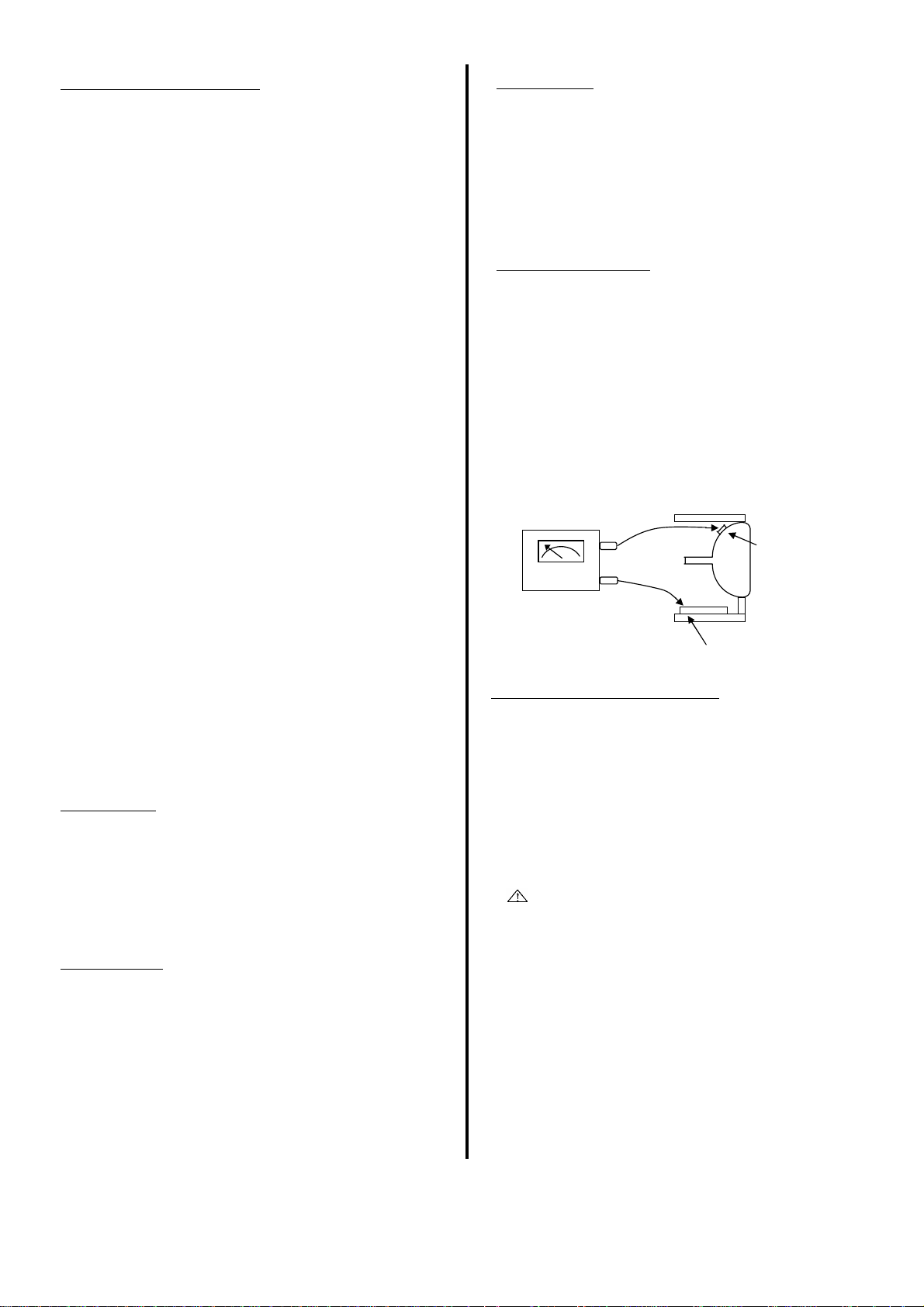
2. When replacing chassis in the cabinet. All the protective voltage in this receiver is lower than 33.0kV. In case any
devices are put back in place , such as ; barriers , non- componant having influence on the high voltage is replaced.
metallic knobs , adjustment and compartment cover or shields, confirm that high voltage with minimum Brightness and contrast
isolation resistors- capacitors, etc. is lower than 35.0kV. To measure H.V. use a high impedance.
3. When service is required, observe the original lead dress. Extra H.V.meter. Connect (-) to chassis earth and (+) to the CRT
care should be taken to assure correct lead dress in the high anode button. (See the following connection diagram.
voltage circuitry area.
4. Always use the manufacturer ' s replacement component.
Especially critical components as indicated on the circuit the connection to the Anode button is made
diagram should not be replaced by other maker.
Furthermore where a short circuit has occurred, replace
those components that indicate evidevce of overheating.
5. Before returning a serviced receiver to the customer, the
service technician must thoroughtly test the unit to be
certain that it is completely safe to operate without danger
of electrical shock, and be sure that no protetive device
built into the instrucment by the manufacturer has became
defactive, or inadvertenly defeated during servicing.
therefore, the following checks are recommended for the Many electrical and mechanical parts in HITACHI television
continued protection of the customers and service receiver have special safety related characteristics. These
techninians. characteristics are often not evident from visual inpection
Insulation resistance between the main poles and a ny wattage, etc. Replacement parts which have these special safety
accessible metal parts should not be less than 7M
CD. Also, no flashover or breakdown should occur during the components having such features are identfied by marking with
dielectric strength test, to apply 4KV AC for one minute a mark in the schematics and on the replacement parts list
between the mains poles and any accessible metal parts. in this Service Manual. The use of a substitute replacement
: The primary source of X radiation in this receiver
is the picture tube. The tube utilized in this chassis is X radiation, or other hazards. Product Safety is continuously under
specially constructed to limit X radiation. review and new instructions are issued from time to time. For the
Fof continued X radiation protection, the replacement tube must latest information, always consult the current HITACHI Service
be the same type as the original, HITACHI approved type. Manual. A subscription to, or additional copies of , HITACHI
Ω at 500V characteristecs are identified in this Service Manual. Electrical
High Voltage
This receiver is provided with a hold down circuit for
erviceman
arning
: Turn the power seitch off without fail before
( + )
( - )
HIGH IMPEDANCE
H.V. METER
CHASSIS GROUND
nor can be protection afforded by them necessarily be obtained
by using replacement components rated for higher voltage,
component which does not have the same safety characteristics
as the HITACHI recommended replacement one shown in the
parts list in this Service Manual, may create electrical shock, fire,
Service Manual may be obtained at a nominal charge from your
HITACHI sales offices.
CRT ANODE
- 2 -
Page 3
TECHNICAL CAUTIONS
k
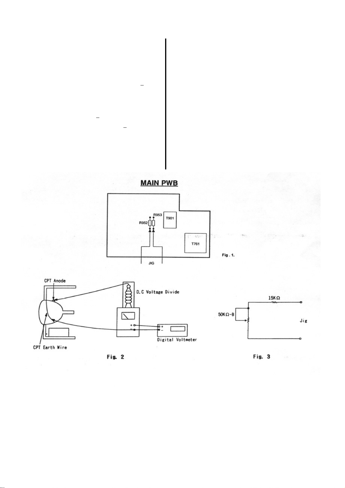
High voltage Iimiter circuit operation chec
1. Connect the high voltage voltmeter between the CPT anode the AC input voltage stabilized at 220 V. turn the picture disapears
(anode cap) and GND (CPT grounding lead). with a high voltage of 34.0 or less.
2. Receive the broadcast signal and set the brightness and 7. Turn the switch of the set to off immediately after the check is
contrast VRs to max. Set the beam current to 1.6mA +
(After cut-off adjustment)
3. Set the AC input voltage to 220 +
4. Check that the constant high voltage is 30.0 +
this time. the chassis because the high voltage may remain at the
5. Turn the switch of the set to off and connect the jig shown in anode cap.
Fig.3 at R952, R953 as shown in Fig 1.
3V. to from the anode cap, be sure to turn the switch of the set
10%. completed.
1.0kV at off and do it after the residual high voltage is discharged to
6. With the brightness and contrast VRs left as set in item. 2 and with
8. Remove the adjust jigs and high voltmeter.
NOTE : When connecting disconnecting the high voltage voltmeter
- 3 -
Page 4

คําแนะนําทางเทคนิค
่
่
้
ขอควรระวังเบื้องตนเพื่อความปลอดภัย แรงดันไฟฟาแรงสูง
ขอควรระวัง : แทนเครื่องของโทรทัศนสีเครื่องนี้ตออยูกับไฟฟา
กระแสสลับ 220 โวลท ขณะเปดเครื
การใชอุปกรณที
ทั้งปฏิบัติตามขอแนะนําเพื่อความปลอดภัยดังนี้ ตลอดเวลา
1. อยาติดตั้ง, ถอดเปลี่ยนหรือถือหลอดภาพ โดยวิธีการที่ไมมีการ
ปองกัน หรือไมสวมแวนตาเพื่อปองกันการแตกของหลอดภาพและ
ใหถือหลอดภาพดวยความระมัดระวังและถือใหหางจากตัวเรา เมื่อไดรับสัญญาณภาพสีดํา แรงดันไฟสูงขณะทํางานที่เครื่อง
2. เมื่อทําการเปลี่ยนแทนเครื่องลงในตูโทรทัศน อุปกรณปองกัน จะมีคาต่ํากวา 33.0 กิโลโวลท ดังนั้นในกรณีที่มีการเปลี่ยนชิ้นสวน
ตางๆ ตองใสกลับไปอยูในสภาพเดิม เชน พวก Knob หรือปุมกด ที่มีความเกี่ยวของกับวงจรแรงดันไฟสูง ใหทําการตรวจสอบแรงดัน
ตางๆ ( ถามี ) หร
3. การซอมในภาคไฟแรงสูง ตองใชอุปกรณเกรดถูกตองตาม และคาแรงดันไฟสูงที่วัดไดตองมีคาไมเกิน 35 กิโลโวลท โดยใน
มาตรฐานกําหนดทุกชิ้นสวน การวัดแรงดันไฟสูงนั้น ตองใชเครื่อง H.V. meter ที่มีความตานทานสูง
4. ใชอุปกรณ อะไหลแทจากบริษัทในการซอมทุกครั้ง โดยสังเกต โดยตอขั
เครื่องหมาย ปรากฏในวงจร ซึ่งหมายถึงการเปลี่ยนอุป- anode (การตอใหดูรูปขางลางประกอบ)
กรณในตําแหนงนั้นๆ จะใชอุปกรณทดแทนหรือเกรดต่ําไมได
เพราะถาเกิดมีการไหมได
5. กอนคืนเครื่องกลับสูลูกคา ชางบริการตองทดสอบจนแนใจ และ
ถูกตองเหมาะสมขณะทําการซอม และโปรดสังเกตรวม แปลง ถาเพิ่มขึ้นก็จะกดระดับคาแรงดันลงทําใหระดับไฟแรงสูงคงที่อยู
ือพวกชีลดปองกันตางๆ ตองตรวจดูใหรอบคอบ ไฟสูง โดยทําการปรับ Brightness และ Contrast ไวที่ตําแหนงต่ําสุด
องรับใหชางบริการพึงระมัดระวังตอ การเปลี่ยนแปลงแรงดันไฟฟา โดยการเปรียบเทียบคาความเปลี่ยน
ภาคจายไฟแรงสูงของโทรทัศนนี้ ใชระบบ HOLD DOWN ควบคุม
ขอควรระวังสําหรับชางบริการ
วลบเขากับกราวดของแผง และตอขั้วบวกเขากับ CRT
หมายเหตุ : ปดสวิทชเครื่องรับกอนตอขั้วบวกกับ ANODE ของหลอดภาพ
ตองตรวจสอบใหแนนอนวา เครื่องจะทํางานในสภาพสมบูรณ และ
ปลอดภัยตอผูใช ตองแนใจวาอุปกรณปองกันเพื่อความปลอดภัย
ของเครื่องที่รับซอมจะไมมีการชํารุดเสียหายเกิดขึ้น และยังทํา
งานไดดี เพราะฉะนั้นตองตรวจการทํางานของวงจรปองกันตาม
ลําดับดังนี้
การตรวจสอบคาความเปนฉนวน
คาฉนวนความตานทานระหวางขั้วทางไฟฟาหลักกับสวนที่เปนโลหะ
ของเครื่องตองมีคาไมนอยกวา 7 เมกะโอหม ที่แรงดันไฟตรง 500 โวลท
ดังนั้น การทดสอบตองไมมีการ Break Down ขณะทําการทดสอบ
คาความเปนฉนวนไฟฟาดวยการจายไฟ 4 kV DC นาน 1 นาที ระหวาง อุปกรณไฟฟาที่ใชในโทรทัศนสีเครื่องนี้ มีคุณสมบัติทางดาน
สวนที่เปนโลหะของแทนเครื่องกับขั้วตอสายไฟฟา ปลอดภัยสูงสุด การเปลี่ยนอุปกรณจึงมีความจําเปนตองใหได
การแผกระจายรังสี เอ็กซ
การเปลี่ยนหลอดภาพ ตองเปนชนิดเดียวกันกับทางโรงงานผูผลิต จากเครื่องหมาย
โทรทัศนดวยเหตุผลการออกแบบที่มีการปองกันการแผกระจาย
HIGH IMPEDANCE
H.V. METER
ขอสังเกตของอุปกรณเพื่อความปลอดภัย
เทามาตรฐานเดิมทั้งคาและอัตรา VOLTAGE ซึ่งตําแหนงอุปกรณ
สําคัญจะมีเครื่องหมายแสดงในรายการอุปกรณในคูมือนี้โดยสังเกต
( + )
CRT ANODE
( - )
กราวดของแผง
ของรังสีเอ็กซที่มีอัตราต่ําที่สุดซึ่งผานการรับรองจากฮิตาชิ
- 4 -
Page 5

คําแนะนําทางเทคนิค
้
่
่
่
การตรวจสอบวงจรควบคุมไฟแรงสูง
1. ตอ HIGH VOLTAGE VOLTMETER กับหลอดภาพโดยตอขั้วบวก 6.จากเงื่อนไขขอ 2 (BRIGHTNESS + CONTRASS = MAX) ที่ 220 VAC
กับ ANODE CAP และขั
2. เปดโทรทัศนรับสัญญาณเมื
และ CONTRAST ใหเต็มที
โดยใหมีคา +
3. ตรวจสอบแรงดันไฟสลับใหได 220 โวลท + 3 โวลท
4. ตรวจสอบแรงดันไฟสูงคงที่ควรเปน 29.5 กิโลโวลท โดยใหมีคา +
5. ปดสวิทชเครื
ภาพที่ 1 ของเครื่องเรียบรอยแลวทุกครั้ง และทําการ DISCHARGE
10% สมบูรณ
องรับแลวตอ JIG ตามภาพที่ 3 โดยตอที่ R952, R953 ตาม จาก ANODE CAP ตองแตใจวาไดปด POWER SWITHC
วลบกับกราวดแทนเครื่อง ปรับภาพใหมืดโดยที่ระดับ H.V. จะอยูที่ประมาณ 34.5 กิโลโวลท หรือ
อมีภาพและเสียงแลวก็ปรับ BRIGHTNESS ต่ํากวาเล็กนอย
ปรับ BEAM CURRENT ใหได 1.6 มิลลิแอมป 7. ปด POWER SWITCH ของเครื่องรับทันที หลังจากตรวจสอบเสร็จ
8. ถอด ADJUST JIGS และ HIGH VOLTAGE VOLTMETER
10%
หมายเหตุ: เมื่อทําการตอหรือถอนสาย HIGH VOLTAGE VOLTMETER
ไฟแรงสูงตกคางกับแทนเครื่องทุกครั้ง
ภาพที่ 2
ภาพที่1
ภาพที่ 3
- 5 -
Page 6
A
A
R
R
Recepstemtion system
Channel coverage
Frequencey range
44MHz-863MHz
SPECIFICATION (รายละเอียดทางเทคนิค)
625-LINES B.G/D.K/H PAL Antenna input 75W COAXIAL IEC TYPE
B.G/D.K/K1 SECAM Color picture tube A68QCU770X56L
NTSC50 Speaker (cm) 6X12 (X2)
525-LINES M/NTSC Sound output 7W X 2
NTSC3.58-5.5/6.0/6.5 751 : AC 240V 50Hz
NTSC4.43-5.5/6.0/6.5
PAL 60, SECAM 60 191
CCIR
Australia : AU0~12, AU28~69
OIRT : R1~12, R21~69 433 , 435
)(
JAPAN : J1~12, J13~69
: E2~12, E21~69, S01~3,
S1~41 071, 98*, 192
Power supply
Power consumption
121, 195
941, 08*, 051
138 W
: AC 127V 50Hz/60Hz
: AC 110V - 240V 50Hz/60Hz
}
: AC 200V - 240V 50Hz/60Hz
}
U.S.
Hong Kong, U.K. : UK21~69
China : C1~12, C13~57, Z1~38
* Soecifcations are subject to change wihout notice to improve performance.
: US2~13, J~W, US14~69 45.5 KG
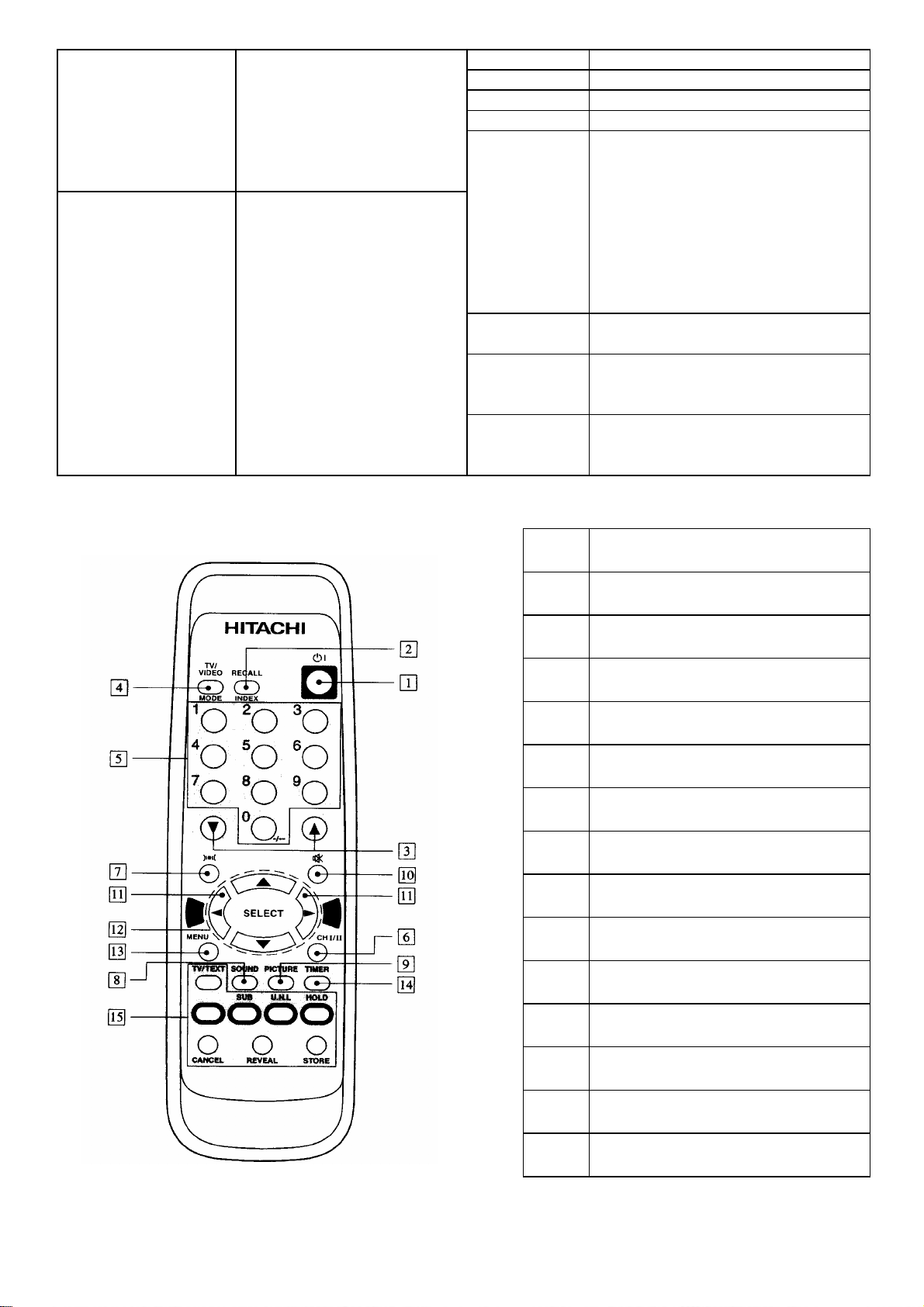
REMOTE CONTROL UNIT (การควบคุมดวยรีโมทคอนโทรล)
Weight (kg)
Dimensions
W x H x D (mm)
1
2
3
4
5
6
7
8
9
10
11
12
13
14
15
768 X 593 X 503 (C29-TF640S)
769 X 593 X 491 (C29-TF650S)
POWER ON/OFFSEITCH
ปุมเปด/ปดเครื่องชั่วขณะ
RECALL
ปุมเรียกดูชองที่กําลังรับชม
PROGRAMME UP/DOWN
ปุมเปลี่ยนชองขึ้น/ลง
INPUT SELECTION
ปุมเลือกสัญญาณเขา
PROGRAMME SELECTO
ปุมเลือกชองรับสัญญาณ
CH I/CH II
ปุมเลือกระบบ 2 ภาษา
SURROUND
ปุมเลือกระบบเสียงรอบทิศทาง
SOUND (Sub - - for T/TEXT)
ปุมเลือกแบบเสียง(ในระบบเทเลเท็กซเปน Sub - -)
PICTUR (U.N.L. - - for T/TEXT)
ปุมเลือกแบบภาพ(ในระบบเทเลเท็กซเปน U.N.L. - -)
MUTE
ปุมหยุดเสียงชั่วขณะ
VOLUME UP/DOWN
ปุมปรับระดับเสียงขึ้น/ลง
CURSO
ปุมเคอรเซอร
MENU
ปุมเรียกรายการคําสั่งปรับแตง
Timer (Hold - - for T/TEXT)
ปุมตั้งเวลา(ในระบบเทเลเท็กซเปน Hold - -)
TELETEXT OPERATING KEYS (081/982only)
ปุมควบคุมเทเลเท็กซ (เฉพาะ 081/982 เทานั้น)
- 6 -
Page 7

/
CONTROL (การควบคุม)
1
7
2
5
8
9
4
6
POWER NO/OFF SWITCH
1
ปุมเปด/ปดเครื่อง
Rear Panel (ดานหลัง)
STANDBY/TIMER INDICATION
2
ไฟแสดงการปดชั่วขณะ/การตั้งเวลา
AERIAL TERMINAL
3
จุดตอสายอากาศ
FUNCTION
4
ปุมเรียกรายการการคําสั่งปรับแตง
REMOTE CONTROL RECEIVER
5
ชองรับสัญญาณจากรีโมทคอนโทรล
AV IN/OUT TERMINAL
6
จุดตอสาย AV เขา/ออก
INPUT SELECT
7
ปุมเลือกสัญญาณเขา
VOLUME UP/DOWN
8
ปุมเพิ่ม/ลด ระดับเสียง
PROGRAMME UP/DOWN
9
ปุมเปลี่ยนชองขึ้น
ลง
- 7 -
Page 8
/
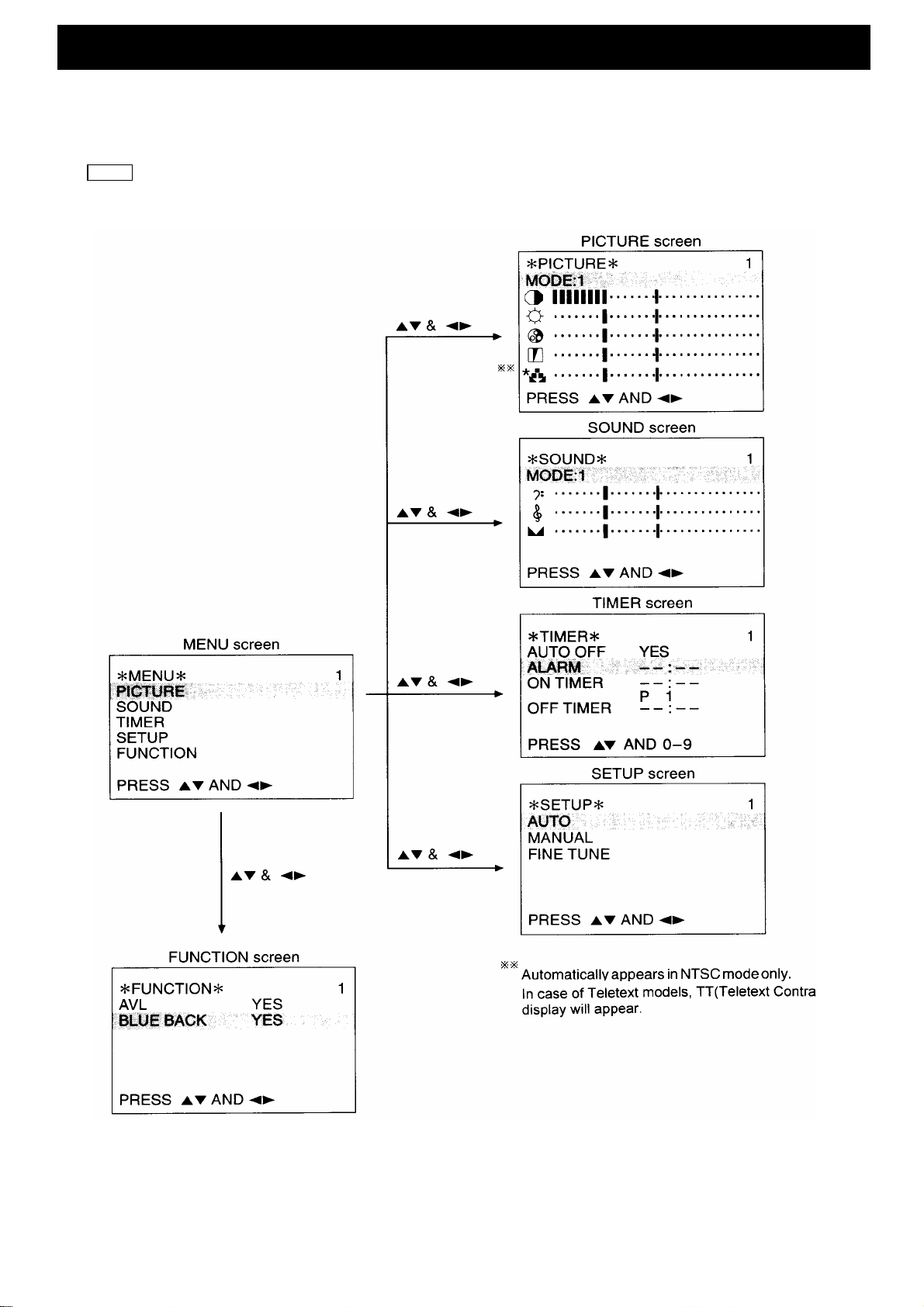
GENERAL ORERATIONS GUIDE (คําแนะนําในการใชงานทั่วไป)
With this TV set, all adjustments/settings are performed by selecting from menu screens.
Different menu screens and details of adjustments/settings are shown below. To access the menu screen, press
MENU
the button, then select the item by pressing the up/down cursor buttons and setting it by pressing the left
right cursor buttons.
- 8 -
Page 9
3
- 9 -
Page 10

้
V
V
V
V5V
V
V
V
V
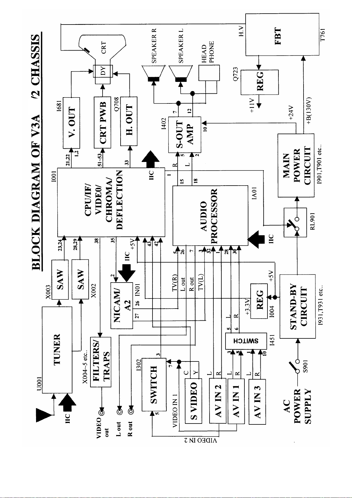
CIRCUIT DESCRIPTION (การทํางานของวงจร)
Selection and CPU circuitry
IC type, TDA9384/86/65, performs functions like IIC controls, channel selection, on-screen
displays, search tuning, systems selection amongst others. The pin's functions of
TDA9384/86/65 are oresebted in the table shown bellow.
ใช IC TDA9384/86/65 ซึ่งใช IIC ในการควบคุมการทํางานตางๆ โดยภายในตัว IC จะประกอบไปดวย วงจรเลือกชองรับสัญญาณ ,
แสดงผลบนหนาจอ , ตั
งชอง , เลือกระบบ , และวงจรการทํางานอื่นๆ โดยตําแหนงขาตางๆที่ใชในการควบคุมการทํางานของ IC
TDA9384/86/65 แสดงตามตารางดางลางนี้
Pin
number
1 3.3
25V
35V
45
5 3.3
65
7 3.3
8 3.3
9
10 3.3
11 3.3
12
13
14
15
16
17
18
19
20
21
22
23
24
25
26
27
28
29
Signal
name
Power
SCL
SDA
Alarm
SAW Sw
AV S-DET
SW FE/AV
Key-In
V2 / V1
VSSC / P
Led
ON/OFF Mute
VSSA
SECPLL
VP2
DECDIG
PH2LF
PH1LF
TV
DECBG
AVL / EWD
VDRB
VDRA
IFIN 1
IFIN 2
IREF Input
VSC
AGCOUT
AUDEEM
DECSDEM
I/O
Output
I/O
I/O
Output
Output
Input
Output
Input
Output
-
Output
Output
-
-
-
-
-
-
-
-
Output
Output
Output
Input
Input
-
Output
Output
-
Configuration
P.P
O.D
O.D
O.D
H.I.
O.D
H.I.
O.D
-
O.D
O.D
- Analog ground of Teletext decoder and digital ground
-
-
-
-
-
-
-
-
-
-
-
-
-
-
-
-
-
O = Stand - by, 1 = on
2
Colck of main I
Data of main I2 C-bus
PWM output for Beep soundO.D
1 = M, 0 = Others
Detect for S-VHS (not mono chassis)
FE/AV switch (mono chassis)
Local analogue keyboard
1=Video:2, 0=Video:1
Digital ground for u-controller core and periphery
LED Drive
1=Mute on, 0=Mute off (Under Standby)
of TV-processor
SECAM PLL decoupling
nd
supply voltage TV-processor (+8V )
2
Decoupling digital supply of TV-processor
Phase2-filter
Phase1-filter
Ground 3 of TV-processor
Bandgap decoupling
East-West drive output
Vertical drive B output
Vertical drive A output
IF input 1
IF input 2
Reference current input
Vertical sawtooth capacitor
Tuner AGC output
Audio deemphasis
Decoupling sound demodulator
C-bus
Function
- 10 -
Page 11

V
่
Pin
number
30
31
32
33
34
35
36
37
38
39
40
41
42
43
44
45
46
47
48
49
50
51
52
53
54
55
56
57
58
59
60
61
62 3.3V
63 3.3V
64 3.3
Signal
I/O
Configuration
name
GND2
SNDPLL -
REFO
HOUT
FBISO Input
AUDEXT Input External audio input-
EHTO
PLLIF - IF-PLL loop filter-
IFOut Output
+8v - Main supply voltage TV-processor ( +8V )-
CVBSINT Input Internal CVBS input-
GND1 - Ground 1 for TV-processor-
CVBS/Yin Input External CVBS input-
Cin Input - Chrominance input ( SVHS )
AUDOUT Output Audio output-
INSSW2 - No connection-
R2/VIN - - No connection
G2/YIN - No connection-
B2/UIN - - No connection
BCLIN Input - Beam current limiter input/V-guard input
BLKIN Input - Black current input
RO Output - Red OSD output
GO Output - Green OSD output
BO Output - Blue OSD output
VPE - - OTP Programming Voltage
VDDC - - Digital supply to core (3.3V)
OSDGND - - Oscillator ground supply
XTA/IN Input -
XTA/OUT Output - Crystal oscillator output
RESET Input -
VDDP - - Digital supply to periphery (+3.3 V)
SCL(EEP) I/O
SDA(EEP) I/O Data of secondary I
RC-In Input O.D
-
-
Output
Output
-
-
- Horizontal output
-
-Input
--VDDA Analog supply of Teletext decoder and digital supply
Function
Gound 2 for TV processor
Narrow band PLL filter
Subcarrier reference output
Flyback input
EHT/overvoltage protection input
IF-video output / selected CVBS output-
of TV-processor (3.3V)
Crystal oscillator input
Reset
2
Clock of secondary I
Input for Remote control decoding
-bus for EEPROM O.D
2
-bus for EEPROM O.D
Note 1: Abbreviation of configuration mode: O.D. Open Drain
( ความหมายของอักษรยอใน comfiguration mode:) Q.B. Quasi-Bidirectional
H.I. High-Impedance
P.P Push-Pull
Note 2: During reset all pins are in Quasi-Bidirectional mode.
(ในระหวางที
ทําการรีเซต ขาทุกขาจะอยูในโหมด Quasi Bidirectional)
- 11 -
Page 12

POWER SUPPLY CIRCUIT
s
้
R
้
้
d
ใ
R
R
้
้
้
1. Stand-dy mode :
Commutating voltage from AC input is rectified by D931~D934 and produces approximately 300V. This high
voltage DC is applied to the primary winding of T931 in series with the integrated high voltage MOSFET inside
the I931 (TNY254). The diode D935, capacitor C936, and resistor R930 comprise the clamp circuit that limit
the turn-off voltage spike on the drain pin 5 of I931 to a safe value. The secondary winding of T931 is rectified
and filtered by D971, C971, L971, and C973 to provide the 5V output. Additional filtering are provided by L972
and C972. The output voltage is determined dy the sum of the opto-coupling I932 forward drop (about 1V)
and zener diode D972 voltage.
วงจรภาคจายไฟ
1. ในสภาวะปดชั่วขณะ :
แรงดันไฟฟากระแสสลับที่เขามา ผานวงจรกรองกระแสโดย D931~D934 ไดเปนแรงดันไฟฟากระแสตรงประมาณ 300V แรงดันไฟฟา
กระแสตรงแรงสูงนี
930 ตอเปนวงจรแคลมปสําหรับจํากัด turn-off voltage spike ที่ขา drain หรือขา5 ของ I931 เพื่อปองกันการเสียหาย สวนแรงดันที่
ขดทุติยภูมิของ T931จะผานวงจรกรองกระแสและทําใหเรียบขึ
ตรงประมาณ 5 V ซึ่งแรงดันดังกลาวนี
กับแรงดันที่ซีเนอรไดโอด D972
จะตอเขาที่ขดปฐมภูมิของ T931 ซึ่งตออนุกรมกับ MOSFET ภายในตัว I931(TNY254) โดย มี D935 , C936 , และ
นโดย D971 , C971 , L971 , และ C973 ไดออกมาเปนแรงดันไฟกระแส
อาจคํานาณไดจากการนําแรงดันไบอัสตรง ตก ครอมที่ opto-coupling I932 (ประมาณ 1 V) รวม
2. Turn-on mode :
When TV set turn-on, the on/off signal from MICON become high, so RL901 turns on, commutating voltage
from AC input is rectified by D901A and produces approximately 300V to pin 3 of I901. Current flowing
through R903, R904, R918, R919 causes I901 pin 4 to initially turn on. Secondary voltage are then induce
winding B1-B2 in T901, I901 supply voltage is obtained via R910, D906, C909, C909A and applied to pin 4 of
I901, thereby maintaining I902 switching operation. Secondary voltage in S1 - S4 winding is rectified by D952
to produce 24V which is smoothed by C956.
Error amplifier Q951 is set to a pre-determined level by resistor network R950~R953, and reference voltage
D953. Should the +B voltage rise, base voltage of transistor Q951 will become more positive, and this difference
is amplified by the error amplified by Q951. An output is applied to I901 feedback pin 1 through opto-coupling
I902 and controls ON time of I901 internal circuit. In this way, +B voltage is regulated and maintained at a
constant level. D959 and D957 offer protection that it should the voltage level rise excessively When standby
mode is selected, RL901 turn off. Only+5V still live
2. ในสภาวะเปดเครื่อง
เมื่อเปดเครื่องรับโทรทัศน สัญญาณ เปด/ปด จาก MICON จะเปน HIGH ทําให RL901 ทํางาน แรงดันไฟฟากระแสสลับที่เขามาจะผาน
วงจรกรองกระแสโดย D901A ไดเปนแรงดันไฟฟากระแสตรงประมาณ 300V
903 , R904 , R918 ,
จากนั
ให I901 แทนโดยมี I902 ทําหนาที่ควบคุมการ Switching แรงดันที่ขดทุติยภูมิที่ S1-S2 จะผานวงจรกรองกระแสโดย D961 เพื่อ
สรางแรงดัน +B 130V แลวทําใหเรียบขึ
และทําใหเรียบขึ
นจะเกิดแรงดันเหนี่ยวนําจากขดทุติยภูมิที่ B1-B2 ใน T901 ใหลผาน R910 , D906 , C909 , C909A ไปยังขา4 เพื่อเปนแหลงจาย
นโดย C956
:
919 เขาที่ขา4 ของ I901 เพื่อใหเริ่มทํางาน
นดวย C956 สวนแรงดันที่ขด S2-S4 จะผานวงจรกรองกระแสโดย D952 เพื่อสรางแรงดัน 24V
- 12 -
หลเขาที่ขา3 ของ I901 โดยจะมีกระแสไฟสวนหนึ่งไหลผาน
Page 13

Q951 เปนวงจรขยายความแตกตาง โดยถูกตั้งคาไวคาหนึ่งดวย R950~R953 และใช D953 เปนตัวกําหนดระดับแรงดันอางอิง ในกรณี
้
้
้
/
/
/
/
้
A
/
K
ที่แรงดัน +B เพิ่มขึ
ขยายความแตกตาง Q951 แรงดันที่ออกจาก Q951 จะถูกปอนกลับไปยังขา1 ของ I951ผานทาง Opto-Coupling I902 เพื่อควบคุม
การเกิด ON-Time ของวงจรภายในตัว I901 ซึ่งจะทําใหระดับแรงดัน +B คงที่ได และมี D956 กับ D957 เปนตัวปองกันระดับแรงดันที่
เพิ่มสูงขึ
นมากเกินไป ในสภาวะปดชั่วขณะ RL901 จะไมทํางาน ภายในวงจรจะมีเพียงแรงดัน +5Vอยู
น แรงดันที่ขาเบสของ Q951 จะเพิ่มขึ้นตาม ความแตกตางของแรงดันที่ขาเบส และขา อิมิเตอร จะถูกขยายโดยวงจร
TUNER AND IF
The Tuner (U001) used on V3AL chassis is powered up by the 5V & 33V supply. It is IIC bus controlled and
covers VHF, UHF, CATV Band (Mid, Super and hyper).
The IF output from Tuner (pin 11 of U001) is applied to the amplifier Q201.
For multi-systems model with M-NTSC, switchable saw filter is used. Q001 at pin 2 of X002 severs to select the
IF signal between M/N mode to other modes (e.g. B/G, D/K) before demodulation is carried out at I001.
i.e. at M mode: Base of Q001 High
I001 (TDA9365/9384/9386) besides begin the microcontroller, incorperates video / chroma / deflections /
teletect features and video/audio switching. It performs auto color identification of PAL/SECAM/NTSC/, sync
separation , AFC, HV oscillator and output RGB signal.
IF signal is sent to I001 pin 23 and 24 for demodulation. The composite video signals after demodulation are sent
to a series of bandpass filters (X004~X006) through pin 38 of I001. The system selection is as follows:
วงจร TUNER AND IF
จูนเนอรที่ใชในแทนเครื่อง V3AL จะใชแหลงจายไฟ 5V และ 33V โดยใช IIC ในการควบคุมการทํางาน ซึ่งสามารถใชไดกับยานความถี่
ง VHF , UHF , CATV (Mid , super และ hyper ) ความถี่ IF จากจูนเนอร (ขา11 ของ U001) จะถูกสงไปขยายที่ Q201 สําหรับรุน
ตางๆ ทั
Multi-systems ที่สามารถรับระบบ M-NTSC ไดจะใช Saw filter แบบ Switchable Q001ที่ขา2 ของ X003 ทําหนาที่ในการเลือกรับ
สัญญาณ IF ระหวางโหมด M
อยางเชน ที่โหมด M ขาเบสของ Q001
I001(TDA9365/9384
ระบบสีโดยอัตโนมัติวาเปนระบบ PAL / SECAM / หรือ NTSC รวมทั
OUTPUT RGB
สัญญาณ IF จะถูกสงไปยังขา 23 และ 24 ของI001 เพื่อทําการแยกสัญญาณตางๆออก ไดเปนสัญญาณ Composite Video แลวผาน
N และโหมดอื่นๆ (อยางเชน B
9386)ซึ่งภายในเปนไมโครคอนโทรลเลอร รวมทั้งวงจร ภาพ / สี / ดีเฟลคชั่น / เทเลเท็กซ / และเสียง จะทําการเลือก
G , D
K) กอนที่จะทําการถอดสัญญาณพาหะออกที่ I001
Hight
งทําการแยกสัญญาณ
FC , H
V ออสซิลเลเตอรและสัญญาณ
วงจรอนุกรม Bandpass filter (X004 ~ X006) ไปยังขา38 ของ I001 ระบบการเลือกรับแสดงตามตารางดานลาง
Signal output to pin 40 of I001
Buffers
Q003
Low
High
Q004
Cut Off
B/G, I, D/
- 13 -
Q005
M
Cut Off
Page 14

The RF video signal after system selection is sent to output AV terminal and returns to pin 40 of I001 for video
้
6
e
e
้
้
/
้
A
A
selection. The external video signal (input AV 1, 2, 3 and S-terminal at pin 42) also goes trough pin 38 output
AV terminal. This is done by use of internal switch control in I001 (video selection).
สัญญาณ RF ภาพที่ผานวงจรเลือกระบบแลวจะถูกสงไปยังวงจร VM และขั้วตอสัญญาณออก AV แลวสงกลับไปยังวงจรเลือก
สัญญาณภาพที่ขา 40 ของ I001 สวนสัญญาณภาพภายนอก (INPUT AV 1 , 2 , 3 และ S-terminal ที่ขา 42) จะถูกสงออกจาก
ขา38 ไปยังวงจร VM และขั
วตอสัญญาณออก AV ซึ่งกระบวนการดังกลาวนี้จะควบคุมโดยสวิทซภายใน I001 (video selection)
VIDEO/CHROMA
The chroma input at S-terminal and the YUV input signals at Video 3 terminal are sent to pin 43, 47, 48 and 4
of I001 respectively for video selection and processing.
I302 selects Video 1 / S-terminal (Yin), Video2 or Video3 (Y input) signals and sent to pin 42 of I001. The Video
input signals (RF at pin 40 and external video at pin 42) is selected again using internal AV switch in I001
controlled by IIC bus. The selected video signals are processed with teletext. After color identification and
decoding, the color difference signals are matrixed with the luminance signal to obtain the RGB signals. Th
RGB can be controlled by contrans and brighness and output at pin 51~53 to CRT PWB, insequence with th
OSD RGB.
Internal sync separator and H/V osillator of I001 produce H and V drive signals which are applied to deflection
circuits for horizontal and vertical scanning.
วงจร VIDEO/CHROMA
สัญญาณ CHROMA ที่เขามาทางขั้วตอ S-terminal และสัญญาณ YUV ที่เขามาทางขั้วตอ VIDEO 3 จะถูกสงไปยังขา43 , 47 , 48 ,
และขา 46 ของ I001ตามลําดับ เพื่อเลือกสัญญาณภาพ และทํากระบวนการอื่นตอไป
I302 จะทําการเลือกสัญญาณจาก Video 1/ S-terminal (Yin) , Video 2 หรือ Video 3 (Y input) และสงไปยังขา42 ของ I001 สัญญาณ
ภาพที่เขามา (RF ที่ขา40 และ External video ที่ขา42 ) จะถูกเลือกอีกครั
หลังจากที่ทําการแยกสัญญาณสีแลว จะไดเปนสัญญาณความแตกตางสี และสัญญาณขาว-ดํา ผานวงจรเมทริกซ เพื่อใหไดสัญญาณ
RGB ซึ่งสัญญาณ RGB นี
วงจร Sync Separator และ H
เพื่อทําการสแกนทางแนวนอน และทางแนวตั
จะควบคุมดวย ความเขม และความสวาง แลวสงออกทางขา 51 ~ 53 ไปยัง CRT PWB พรอมดวย OSD RGB
V Oscillator ใน I001 จะทําการผลิตสัญญาณ H Drive และ V Drive แลวทําการสงไปยังวงจรดีเฟลคชั่น
ง
งโดย AV Switch ที่อยูภายใน I001 ซึ่งควบคุมดวย IIC bus
UDIO MODE SWITCHING
For NICAN/A2 sound models, the IF signal to pin 1 of X002 (saw filter) and output at pin 4 and 5 to pin 28
and 29 of I001. After demodulation, the audio signal output at pin 35 to NICAM PWB (pin 2 or EN01) for NICAM
pricessing. The NICAN audio output at pin L (pin 10) and R (pin11) of EN01 goes to pin 3 and 5 of audio
processor (IA01) respectively. Audio selection and sound processing are carried out.
V STEREO sound models, the mono audio signal after demodulation is output at pin 44 of I001. It goes
For
to pin 3 and 5 of IA01 for audio selection and sound processing.
I451 selects L and R audio input between Video 1 and Vedio 3 terminals and sent to pin 28 and 30 of IA01
respectively. The L and R audio input at Video 2 terminal is also sent to pin 32 and 1 of IA 01 respectively.
- 14 -
Page 15

Audio switching, volume control, treble and bass are processed at IA01 (TDA9859). The L (pin 26) and R (pin7)
R
A
A
้
A
้
A
้
A
A
A
A
้
้
x
output at IA01 goes to output AV terminal. The L (pin 18) and R (pin 15) at IA01 goes to I402 for amplification
before sending to the speakers.
วงจร AUDIO MODE SWITCHING
สําหรับรุนที่มี NICAM/A2 สัญญาณ IF จะเขาที่ขา1 ของ X002 (saw filter) แลวออกที่ขา4 และขา5 ไปยังขา28 และขา29 ของ I001
หลังจากทําการแยกสัญญาณแลัว สัญญาณเสียงจะออกที่ขา35 ไปยัง NICAM PWB (ขา2 ของ EN01) เพื่อทํากระบวนการของ NICAM
สัญญาณเสียง NICAM ที่ไดจะออกมาทางขา L (ขา10) และขา R (ขา11) ของ EN01 ไปยังขา3 และขา5 ของวงจร AUDIO PROCESSO
(I
01) ตามลําดับ
สําหรับรุนมีเสียง AV STEREO สัญญาณเสียงแบบ MONO หลังจากผานการแยกสัญญาณแลวจะออกทางขา44 ของ I001 ไปยังขา
3 และขา5 ของ I
I451 จะทําการเลือกสัญญาณเสียงเขา L และ R ระหวางขั
สวนสัญญาณเสียงเขา L และ R ที่ขั
กระบวนการเลือกสัญญาณเสียง , ควบคุมระดับเสียง , ปรับเสียงทุมและเสียงแหลม จะเกิดขึ
เสียง L(ขา26) และ R (ขา7) จะออกจาก I
จะสงไปยัง I402 เพื่อทําการขยายใหแรงขึ
01 ซึ่งเปนวงจร Audio Selection และ Sound Processing
วตอ Video 1 และ Video 3 แลวสงไปยังขา28 และขา30 ของ I
วตอ Video 2 จะถูกสงไปที่ขา32 และ ขา1 ของ I
01 ไปยังขั้วตอสัญญาณออก AV สวนสัญญาณเสียง L (ขา18) และ R (ขา15) ที่ I
น กอนสงไปยังลําโพง
01
นที่ I
01 (TD
01
9859) สัญญาณ
01
FAILURE DETECTING FUNCTION OF MAIN DEVICES
(การตรวจสอบขอผิดพลาดของอุปกรณหลัก)
In V3AL, failure of Main devices can detect by the blinking indication of LED at front panel. (Example: LED
blinking time is 2 in cycle I002 is out of order.)
If an IIC error occurred, the LED, D001 blinks at 1Hz, 50% duty cycle.
The blinking times are as below.
ในแทนเครื่อง V3AL จะสามารถตรวจสอบขอผิดพลาดของอุปกรณหลักไดจากการกระพริบของ LED ที่ดานหนาเครื่องรับ
(ตัวอยางเชน: LED กระพริบ 2 ครั
ถาปรากฏวา IIC เกิดการผิดพลาด LED D001 จะกระพริบที่ 1 Hz หรือ 50% ของ Duty cycle เวลาการกระพริบแสดงตามตารางดานลาง
Failure Device
Eeprom, AT24C04
UOC, TDA935x/6x/8
Audio Processor, TDA9859
PLL Tuner, TUHIF4EG-772F2
NICAM, MSP3415D / MSP3417D
Table 3.Error LED blinking times
ตารางที่ 3. จํานวนการกระพริบของ LED ในกรณีเกิดการผิดพลาด
งในหนึ่งคาบเวลา I002 ไมทํางานตามคําสั่ง)
CCT.No.
I002
I001
IA01
U001
IN01
- 15 -
Bus Error LED
Blinking Time
2
3
4
5
6
Page 16

EEPROM
r
r
r
A
CCT.No. I002
[AT24C04]
ON
OFF
V/C/J TV Processo
CCT.No. I001
[TDA935x/6x/8x]
HiFi Audio Processo
CCT.No. IA01
[TDA9859]
PLL Tune
CCT.No. U001
[TUHIF4EG-772F2]
SOUND DECODER /
DEMODULATION
CCT.No. IN01
[MSP3415 / MSP3417]
ON
OFF
ON
OFF
ON
OFF
ON
OFF
2S 0.5S
Figure 1. Error LED blinking times
รูปที่ 1.เวลาการกระพริบของ LED ในกรณีเกิดการผิดพลาด
ADJUSTMENT INSTRUCTIONS
. IIC ADJUSTMENTS
Most of the adjustment items in the V3AL chassis are controlled by IIC. Adjustment items include video
chroma IC (I001, UOC) control, sound multiplex Ics, horizontal & vertical deflection and other.
To start the Iic adjustment, first turn off AC power switch. Press and hold down the TV/Video local key and then
press the power switch. Release both buttons after the following display appears on screen.
No. DATA
001 : 28
002 : 28 Select the Adjust items by or cursor
003 : 28
004 : 80
005 : 80
006 : 06 Select the Adjust items by or cursor
007 : 75
: ADJUST
RECALL : SAVE
- 16 -
Page 17

To select the adjustment items (e.g. RGB level, sub-brightness level etc…), press the or cursor button
t
t
A
Y
Y
R
R
A
on Remote control handset. To adjust the data of selected item, press or cursor bitton on Remote
control handse
After completing the adjustments, press the RECALL buttom on Remote control handset to memorize the data.
Press MENU button or turn off the TV set to end the IIC adjustment.
The following are the IIC Bus control and adjustment data for reference.
Table 1: IIC-Bus Control and Adjustmen
ADJ INITIAL
NO. DAT
NAME OF ADJUSTMENT
DAT
RANGE
(hex)
WHITE POINT
1
WHITE POINT G
2
WHITE POINT B
3
HORIZONTAL POSITION
6
SUB-COLOR
*7
SUB-TINT
*8
SUB-BRIGHT
*9
SUB-CONTRAST
*10
SUB-SHARPNESS
11
PHASE 1 TIME CONSTANT
13
VIDEO IDENT MODE
14
FIELD FREQ.
15
INTERLACE
16
ENABLE FAST BLANKING
17
SYNCHRONIZATION
18
COLOR DECODER MODE
19
RGB BLANKING
20
BLACK CURRENT STABILISATION
21
BLACK LEVEL OFF SET
22
BLACK LEVEL OFF SET G
23
VERTICAL DIVIDER MODE
24
SEARCH TUNING MODE
25
VIDEO IDENT MODE
26
FORCED SLICING LEVEL FOR V.S
27
ENABLE VERTICAL GUARD
29
SERVICE BLANKING
30
MATRIX NTSC
31
PAL,SECAM/NTSC
32
BYPASS OF CHROMA BASE BAND DL
33
AVL/SUBCARRIER
34
SYNCHRONIZATION OF OSD/TEXT
35
AFC WINDOW
36
IF SENSITIVIT
37
00-3F
00-3F
00-3F
00-3F
00-3F
00-3F
00-3F
00-3F
00-3F
00-03
00-01
00-03
00-01
00-01
00-01
00-0F
00-01
00-01
00-0F
00-0F
00-01
00-01
00-01
00-01
00-01
00-01
00-01
00-01
00-01
00-03
00-01
00-01
00-01
00 O
00 O
00 O
16 O
1E X
1E X
1E X
08 X
1E X
00 X
01 X
02 X
01 X
00 X
00 X
08 X
00 X
01 X
00 X
00 X
00 X
00 X
01 X
01 X
00 X
00 X
01 X
01 X
00 X
00 X
01 X
01 X
00 X
ITEMS AFFECTED DURING CHANGE
MEMORY
I002
O
O
O
O
O
O
O
O
O
O
O
O
O
O
O
O
O
O
O
O
O
O
O
O
O
X
O
O
O
O
O
O
O
CPT
TDA9384/86/65
I001
O
O
O
O
O
O
O
O
O
O
O
O
O
O
O
O
O
O
O
O
O
O
O
O
O
O
O
O
O
O
O
O
O
*In Video 3 mode, IIC data of adj. Number 7, 8, 9, & 10
must be set separately from RF, Video1 & Video2 mode.
- 17 -
Page 18

ADJ INITIAL
A
X
Y
Y
L
A
NO. DAT
NAME OF ADJUSTMENT
DAT
RANGE
(hex)
VIDEO MUTE
39
AGC TAKE OVER
40
PLL DEMODULATOR FREQ.
47
VERTICAL ZOOM
48
SW-OFF V-OVERSCAN
50
CHROMA BANDPASS C-FREQ.
51
VERTICAL SHIFT(V POSITION)
54
VERTICAL AMPLITUDE(V SIZE)
55
S-CORRECTION
57
BLACK STRETCH
58
VERTICAL SLOPE
59
HOLIZONTAL PARALLELOGRAM
60
HOLIZONTAL BOW
61
AUTO COLOR LIMITTING
63
IF AGC SPEED
64
CATHODE DRIVE LEVEL
66
FAST FILTER IF-PL
69
FORCED COLOR-ON
71
GAIN FM DEMODURATOR
72
SOUND MUTE
73
WINDOW SELECTION SOUND PLL
74
QSS OUT OR AM OUT
75
EHT TRACKING MODE
76
RGB/YUB SWITCH
77
RGB BLANKING MODE
78
V-SCAN DISABLED
80
EW WIDTH
106
EW PARABOLA/WIDTH
107
EW UPPER CORNER PARABOLA
108
EW LOWER CORNER PARABOLA
109
EW TAPEZIUM
110
Y DELA
111
Y DELA
112
113 00
DISABLE
114 00
X-RAY PROTECTION
115 0F
BRIGHNESS OF OSD
116 0F
BRIGHTNESS OF TEXT
139 0F
A2 STEREO JUDGE>
140 F2
A2 BILINGUAL JUDGE>X
141 380
FM-AM SWITCHING
142 7A
OUTPUT LEVEL OF NICAM
143 74
OUTPUT LEVEL OF A2 00-7F
144 75
OUTPUT LEVEL OF FM
00-01 O O
00-3F O O
00-05 O O
00-3F O O
00-01 O O
00-01 O O
00-3F O O
00-3F O O
00-3F O O
00-01 O O
00-3F O O
00-3F O O
00-3F O O
00-01 O O
00-03 O O
00-0F O O
00-01 O O
00-01 O O
00-01 O O
00-03 O O
00-01 O O
00-01 O O
00-01 O O
00-01 O O
00-01 O O
00-01 X O
00-3F O O
00-3F O O
00-3F O O
00-3F O O
00-3F O O
00-0F O O
00-0F O
00-01
00-01
00-0F
00-0F
00-7F
80-FF
000-3FF
00-7F
00-7F
00 X
20 X
02 X
19 X
00 X
00 X
28 O
1B O
20 O
01 X
1B O
1B O
1B O
01 X
01 X
0F X
00 X
00 X
00 X
03 X
00 X
00 X
00 X
00 X
00 X
00 X
1F O
1F O
1F O
1F O
1F O
06 X
0A X
ITEMS AFFECTED DURING CHANGE
MEMORY
I002
O
O
O
O
O
O
O
O
O
O
CPT
X
X
X
X
X
X
X
X
X
X
TDA9384/86/65
I001
O
O
O
X
X
X
X
X
X
X
X
- 18 -
Page 19

+B ADJUSTMENT
A
e
A
x
r
PREPARATION
1. AC input voltage 230 + 5V(50Hz) 1.
djust R954 to obtain +B voltage as below
PROCEDURES
2. Turns on the set and set the brightness
and contrast to Max. 130 +
0.5V
(Signal : Philips Pattern)
3. After 30 sec heat-run, check & adjust the
Measuring Points
+B voltage +B voltage : C935 + side
GND : C935 - sid
VERTICAL CENTER ADJUSTMENT
PREPARATION PROCEDURES
1. Turns on the TV set & heat run about 5 min. 1. Select the IIC control address No. 54.
2. Receive the circular pattern signal 2. Set the horizontal center line to vertical center maker
3. AC 230 +
5V of CRT by adjustment of IIC.
i.e.
Vertical center
marker of CRT
VERTICAL SIZE ADJUSTMENT
PREPARATION PROCEDURES
1. Turns on the TV set & heat run about 5 min. 1. Select the IIC control address No. 55.
2. Receive the circular pattern signal 2.
3. Set all picture settings as below. i.e.
i.e. Contrast : Ma
Brightness : Cente
4. AC 230 + 1V
djust IIC data to obtain the following condition.
Picture Top : Inner circle reach the edge of TV raster.
Picture Bottom : Inner circle reach the edge of TV
raster.
3. Receive the NTSC circular signal, and check the
picture size after the above V-size adjustment.
If a> 0mm, go back to Iic control No. 54(V-center
adjustment) and increase the IIC data by 1 position.
PAL
…………………………………..
……………………
a
NTSC
- 19 -
Page 20

VERTICAL SLOPE ADJUSTMENT(Must be done before V. Center and V. Size Adjustments)
x
r
A
A
T
A
A
PREPARATION PROCEDURES
1. Turns on the TV set & heat run about 5 min. 1. Select the IIC control address No. 30.
2. Receive the circular pattern signal (PLL) 2. Press or key on remote con. handset so
3. Set all picture settings as below. that the button half of the picture is blanked.
i.e. Contrast : Ma
Brightness : Cente
4. AC 230 +
1V picture blanked
i.e.
Botton half of
3. Select the IIC Control address No. 59.
4.
djust the vertical slope until the horizontal center
line is just at the position where the blanking start.
5. Select the IIC Control address No. 30.
6. Press or key on remote con. handset so
that picture appears again.
HORIZONTAL PHASE ADJUSTMENT
PROCEDURESPREPARATION
1. Receive the circular pattern signal. 1. Select the IIC control address No. 06.
2.
djust the picture center to meet the CRT geometrical
centre.
HORIZONTAL SIZE ADJUSTMEN
PREPARATION
1. Receive the HITACHI Circular pattern signal (PAL). 1. Select the IIc control address No. 106
2. Set the contrast at Max, and other at Center. 2.
(Perform this adjustment after H. Phase Adjustment)
djust the picture size so that the average reading of
right and left is 2.0 +
2.0
PROCEDURES
0.5.
2.0
SIDE PIN DISTORTION ADJUSTMENT(Perform this adjustment after H. Phase, H. Size, Vertical Size &
V.position Adjustments) .
PREPARATION PROCEDURES
1. Receive the Cross Hatch signal pattern . 1. Select the IIC control address No. 107.
2. Set the Contrast at Max, and others at Center. 2.
- 20 -
djust the vertical lines are straight except the 1st
outer vertical lines (R/L) .
Page 21

WHITE BALANCE ADJUSTMENT
A
A
e
A
n
n
r
PROCEDURES
1. Switch on the TV set for at least 20 mins. 1. Set black stretch (IIC service no. 58) to "0".
2. Adjust this adjustment after the Purity adjustment. 2. Set to lateral line mode (IIC service no. 80) from
3. Ensure the vertical incident illumination on CRT "0" to "1".
surface to be 20 lux or less. 3. Turns the Screen VR of FBT clockwise and set it to
4. Receive the white balance raster.
5. Turns the low bright adjustment VRs R830, R831 & 4. Takes the first appeared color as the reference,
R832 fully counterclockwise. adjust R830(Green), R831(Blue) & R832(Red) till all
6. Selecr the IIC control address No. 01 (White point red), appear to the same level as the reference color.
No. 02 (White point green), No. 03 (White point bule) Note : Don't turn the VR of the reference color.
and set all data to 1FH 5.
7. Turns the screen VR of FBT fully counterclockwise. line is just slightly seen.
8. Select the IIC control address No. 10 (Sub-contrast) 6. Release the lateral line mode by changing IIC service
and set the data to 1FH. no. 80 from "1" to "0".
9. Select the IIC control address No. 09 (Sub-brightness) 7. Set black stretch (IIC service no. 58) to "1".
and set the data to 26H. 8. Set the White Balance meter probe at the center of
the position where the bright color line starts to appear.
djusts the Screen VR of FBT until the white raster
the screen.
9.
djusts the following keys of IIC and R830/R831/R832
to the desired W/B color temperature.
IIC Address No
R Drive 01
B Drive 03
Notes :
a. Fix the G Drive at 1FH(IIC Address No. 02),
do not adjust.
b. To obtain the low brightness and high
brightness conditions, adjust the brightness
control of remote control handset.
SUB-TINT ADJUSTMENT
PREPARATION PROCEDURES
1. Receive the color bar signal (NTSC). 1. Select the IIC control address No. 08.
2. Set the user control to Contrast: Max, Other: Center. 2. Set IIC address No. 08 to 1E.
SUB-BRIGHTNESS ADJUSTMENT
PREPARATION PROCEDURES
1. Switch on the TV set for at least 20 min. 1. Select the IIc control address No. 09
2. Ensure the vertical incident illumination on CRT surfac
to be 20 lux or less. portion becomes lighter black
3. Receive the color bar pattern.
4. Set the following setting by remote control handset.
Contrast : mi
Color : mi
Brightness : Cente
2.
djust the data until A2 portion becomes black and A3
A7 A6 A5 A4 A3 A2 A1
complete black
lighter black
- 21 -
Page 22

- 22 -
Page 23

- 23 -
Page 24

- 24 -
Page 25

- 25 -
Page 26

- 26 -
Page 27

REPLACEMENT PARTS LIS
T
PRODUCT SAFETY NOTE : Components marked with a have special characteristics important to safety.
Before replacing any of these components, read carefully the PRODUCT SAFETY NOTICE of this Service Manual.
Don't degrade the safety of the receiver thought improper servicing.
SYMBOL PART SYMBOL PART
No. No. No. No.
#0018
NA02493
#0020
NA02501
#0022
4319361A
#0120
MB00453
#0121
4520881
#06
3746073
#0661
3446475
#0681
MA01314
#0682
4520889
#0683
8821234
#0710
NJ03323T
#0781
MA00141
#0782
4520883
#0901
MB00542
#0902
4520883
#0906
3446473
#0907
4340683C
#0908
4520883
#0910
3446852
#900
3720501
B001
JK07781C
BC01 TPB4000201U C050
C002
0800325R
C003
0800291R
C004
0880039R
C005
0244120R
C006
0800288R
C007
0800316R
C008
0800023R
C009
0800288R
C012
0890115R
C013
0890115R
C016
0800324R
C017
0244139R
C018
0800325R
C019
0244139R
C021
0880048R
C022
0880044R
C023
0880044R
C024
0880039R
CHAS MTG METAL A4YR
CHAS MTG METAL A4YL
SCREW BTZ 3x12 MC
HEAT SINK
M3X8 SCREW WITH WASHER CAP ECQB FILM 0.022UF K 50V
IEC CORD HANGER
HEAT SINK MILL FINISHED H50
HEAT SINK
M3X10 SCREW WITH WASHER
NUT M3
FBT HOLDER
HEAT SINK
M3X12 SCREW WITH WASHER
VTM HEAT SINK
M3X12 SCREW WITH WASHER
HEAT SINK MILL FINISHED H30
SO 12V HEAT SINK
M3X12 SCREW WITH WASHER
HEAT SINK A5052P H34
LEAD CLAMPPER
MAIN PWB
CPT PCB 25V3AL
CAP ELECT SMG 100UF 10V
CAP ELECT SMG 10UF 16V
CAP ECQB FILM 0.0047UF K 50V
CAP CER B 820PF 50V K
CAP ELECT SMG 4.7UF 50V
CAP ELECT SMG 47UF 10V
CAP ELECT SME 22UF 16V
CAP ELECT SMG 4.7UF 50V
CAP CER CH 12PF 50V J
CAP CER CH 12PF 50V J
CAP ELECT SMG 100UF 6.3V
CAP CER B 1000PF 50V K
CAP ELECT SMG 100UF 10V
CAP CER B 1000PF 50V K
CAP ECQB FILM 0.022UF K 50V
CAP ECQB FILM 0.01UF K 50V
CAP ECQB FILM 0.01UF K 50V
CAP ECQB FILM 0.0047UF K 50V
NOTE DESCRIPTION NOTEDESCRIPTION
C025
0880037R
C026
0800279R
C027
0880198R
C028
0880198R
C029
0880048R
C030
0800282R
C031
0248686R
C032
0880016R
C035
0880044R
C037
0880016R
C038
0880014R
C039
0800324R
C040
0880012R
C040A
0880194R
C041
0244139R
C042
0880016R
C044
0880012R
C046
0880012R
C047
0800324R
C048
0244139R
C049
0800324R
0880012R
C051
0800326R
C052
0800352R
C053
0800316R
C056
0880051R
C057
0880044R
C201
0880016R
C202
0800325R
C204
0800358R
C205
0800003R
C206
0800041R
C209
0880044R
C210
0800324R
C302
0880048R
C303
0880048R
C304
0880048R
C305
0800288R
C306
0800291R
CAP ECQB FILM 0.0033UF K 50V
CAP ELECT SMG 1UF 50V
CAP POLY FILM 0.22UF J 50V MMT
CAP POLY FILM 0.22UF J 50V MMT
CAP ELECT SMG 2.2UF 50V
CAP CER SL 120PF 50V J
CAP POLY FILM 0.1UF K 50V AMZ
CAP ECQB FILM 0.01UF K 50V
CAP POLY FILM 0.1UF K 50V AMZ
CAP MYLAR 0.047UF K 50V AMZ T
CAP ELECT SMG 100UF 6.3V
CAP MYLAR 0.022UF K 50V AMZ T
CAP MYLAR 0.1UF-K50V
CAP CER B 1000PF 50V K
CAP POLY FILM 0.1UF K 50V AMZ
CAP MYLAR 0.022UF K 50V AMZ T
CAP MYLAR 0.022UF K 50V AMZ T
CAP ELECT SMG 100UF 6.3V
CAP CER B 1000PF 50V K
CAP ELECT SMG 100UF 6.3V
CAP MYLAR 0.022UF K 50V AMZ T
CAP ELECT SMG 100UF 16V
CAP ELECT SMG 470UF 10V
CAP ELECT SMG 47UF 10V
CAP ECQB FILM 0.033UF K 50V
CAP ECQB FILM 0.01UF K 50V
CAP POLY FILM 0.1UF K 50V AMZ
CAP ELECT SMG 100UF 10V
CAP ELECT SMG 1000UF 6.3V
CAP ELECT SME 1UF 50V
CAP ELECT SME 47UF 16V
CAP ECQB FILM 0.01UF K 50V
CAP ELECT SMG 100UF 6.3V
CAP ECQB FILM 0.022UF K 50V
CAP ECQB FILM 0.022UF K 50V
CAP ECQB FILM 0.022UF K 50V
CAP ELECT SMG 4.7UF 50V
CAP ELECT SMG 10UF 16V
- 27 -
Page 28

REPLACEMENT PARTS LIS
T
PRODUCT SAFETY NOTE : Components marked with a have special characteristics important to safety.
Before replacing any of these components, read carefully the PRODUCT SAFETY NOTICE of this Service Manual.
Don't degrade the safety of the receiver thought improper servicing.
SYMBOL PART SYMBOL PART
DESCRIPTION NOTE DESCRIPTION NOTE
No. No. No. No.
C307
C308
C309
C310
C311
C312
C313
C351
C352
C353
C354
C355
C356
C357
C358
C359
C360
C361
C362
C408
C409
C411
C412
C413
C415
C416
C418
C419
C441
C445
C451
C452
C453
C454
C455
C456
C602
C603
C604
C606
0800288R
0800288R
0800291R
0800291R
0880044R
0800316R
0800325R
0800352R
0800291R
0800291R
0244139R
0244139R
0244139R
0244139R
0244139R
0244139R
0800294R
0800279R
0800279R
0800291R
0800291R
0800308R
0800326R
0800291R
0890081R
0890081R
0800361F
0800361F
0880057R
0800368F
0880044R
0800316R
0800291R
0800291R
0800291R
0800291R
0880044R
0279693R
0880044R
0880057R
CAP ELECT SMG 4.7UF 50V
CAP ELECT SMG 4.7UF 50V
CAP ELECT SMG 10UF 16V
CAP ELECT SMG 10UF 16V
CAP ECQB FILM 0.01UF K 50V
CAP ELECT SMG 47UF 10V
CAP ELECT SMG 100UF 10V
CAP ELECT SMG 470UF 10V
CAP ELECT SMG 10UF 16V
CAP ELECT SMG 10UF 16V
CAP CER B 1000PF 50V K
CAP CER B 1000PF 50V K
CAP CER B 1000PF 50V K
CAP CER B 1000PF 50V K
CAP CER B 1000PF 50V K
CAP CER B 1000PF 50V K
CAP ELECT SMG 10UF 50V
CAP ELECT SMG 1UF 50V
CAP ELECT SMG 1UF 50V
CAP ELECT SMG 10UF 16V
CAP ELECT SMG 10UF 16V
CAP ELECT SMG 33UF 16V
CAP ELECT SMG 100UF 16V
CAP ELECT SMG 10UF 16V
CAP CER B 330PF 50V K
CAP CER B 330PF 50V K
CAP ELECT SMG 1000UF 16V
CAP ELECT SMG 1000UF 16V
CAP ECQB FILM 0.1UF K 50V
CAP ELECT YK 2200UF 25V
CAP ECQB FILM 0.01UF K 50V
CAP ELECT SMG 47UF 10V
CAP ELECT SMG 10UF 16V
CAP ELECT SMG 10UF 16V
CAP ELECT SMG 10UF 16V
CAP ELECT SMG 10UF 16V
CAP ECQB FILM 0.01UF K 50V
CAP POLY FILM 0.1UF K 100V AMZ
CAP ECQB FILM 0.01UF K 50V
CAP ECQB FILM 0.1UF K 50V
C607
C608
C610
C612
C681A
C683
C723
C725
C726
C727
C728
C729
C730
C732
C733
C744
C745
C746
C747
C750
C751
C752
C753
C754
C755
C756
C758
C759
C760
C761
C763
C780
C781
C782
C783
C783A
C784
C785
C786
C790
0254501R
0279693R
0880194R
0880194R
0880053R
0244507R
0299918F
0800326R
AN01069F
0880044R
0299720F
0299720F
0259471R
0243507R
0890081R
AL00911
0800326R
0800324R
0800291R
0800328R
0800329R
0244501R
0244501R
0800362F
0800361F
0253974F
0880057R
0244501R
0800291R
0279693R
0800326R
0247842R
0262407F
0244202
AJ00134R
AJ00134R
AN01167F
0244507R
0244501R
0244505R
CAP ELECT KME 10UF 16V
CAP POLY FILM 0.1UF K 100V AMZ
CAP MYLAR 0.1UF-K50V
CAP MYLAR 0.1UF-K50V
CAP ECQB FILM 0.047UF K 50V
CAP CER B 3300PF 500V K
CAP POLY FILM 0.022UF 200V K
CAP ELECT SMG 100UF 16V
CAP POLY 0.012UF 2KV
CAP ECQB FILM 0.01UF K 50V
CAP POLY FILM 0.015UF J 630V
CAP POLY FILM 0.015UF J 630V
CAP ELECT UHA(BP) 6.8UF 50V
CAP CER B 330PF 500V K
CAP CER B 330PF 50V K
CAP ELECT KMF 220UF 160V
CAP ELECT SMG 100UF 16V
CAP ELECT SMG 100UF 6.3V
CAP ELECT SMG 10UF 16V
CAP ELECT SMG 100UF 35V
CAP ELECT SMG 100UF 50V
CAP CER B 1000PF 500V K
CAP CER B 1000PF 500V K
CAP ELECT SMG 1000UF 25V
CAP ELECT SMG 1000UF 16V
CAP ELECT SME 33UF 250V
CAP ECQB FILM 0.1UF K 50V
CAP CER B 1000PF 500V K
CAP ELECT SMG 10UF 16V
CAP POLY FILM 0.1UF K 100V AMZ
CAP ELECT SMG 100UF 16V
CAP CER SL 33PF 500V J
CAP POLY FILM 0.0018UF J 1.8KV
CAP CER 470PF 2KV
CK45-R3DD102K 1N 2KV
CK45-R3DD102K 1N 2KV
CAP DHSM FILM 0.18UF J 250V
CAP CER B 3300PF 500V K
CAP CER B 1000PF 500V K
CAP CER B 2200PF 500V K
- 28 -
Page 29

REPLACEMENT PARTS LIS
T
PRODUCT SAFETY NOTE : Components marked with a have special characteristics important to safety.
Before replacing any of these components, read carefully the PRODUCT SAFETY NOTICE of this Service Manual.
Don't degrade the safety of the receiver thought improper servicing.
SYMBOL PART SYMBOL PART
DESCRIPTION NOTE DESCRIPTION NOTE
No. No. No. No.
C791
C801
C802
C803
C805
C901
C901A
C902
C903
C904
C905
C906
C906A
C907
C908
C909
C909A
C910
C911
C912
C913
C914
C931
C932
C933
C934
C935
C936
C937
C937A
C950
C952
C953
C954
C955
C956
C957
C958
C959
C960
AN01169F
0890086R
0890086R
0890086R
AJ00559
AN01443S
2338314
AN01443S
0248593F
0248593F
0248594F
AL00097
AL00097
0244212
0244120R
0800327R
0800318R
0890079R
AJ00542F
0880048R
0800279R
AJ00454F
0248593F
0248593F
0248594F
AL00059
0880057R
AJ00454F
0243503R
0243503R
0800328R
0244718
AL00911
0800288R
0243507R
0253934F
0800328R
0243509R
0880053R
0800324R
CAP POLY 0.22UF 250V
CAP CER B 820PF 50V K
CAP CER B 820PF 50V K
CAP CER B 820PF 50V K
CAP CER 2200PF K 2KV
CAP POLY 0.1UF-M 250V
DIODE RBV-406M(LF-A)
CAP POLY 0.1UF-M 250V
CAP CER F 4700PF 250V Z
CAP CER F 4700PF 250V Z
CAP CER F 10000PF 250V Z
CAP ELECT KMH 180UF 450V
CAP ELECT KMH 180UF 450V
CAP CER 1200PF 2KV
CAP CER B 820PF 50V K
CAP ELECT SMG 100UF 25V
CAP ELECT SMG 47UF 25V
CAP CER B 270PF 50V K
CAP CER B 4700PF K 1KV
CAP ECQB FILM 0.022UF K 50V
CAP ELECT SMG 1UF 50V
CAP CER 1000PF 1KV
CAP CER F 4700PF 250V Z
CAP CER F 4700PF 250V Z
CAP CER F 10000PF 250V Z
CAP ELECT 4.7UF 450V
CAP ECQB FILM 0.1UF K 50V
CAP CER 1000PF 1KV
CAP CER B 150PF 500V K
CAP CER B 150PF 500V K
CAP ELECT SMG 100UF 35V
CAP CER B 330PF K 2KV
CAP ELECT KMF 220UF 160V
CAP ELECT SMG 4.7UF 50V
CAP CER B 330PF 500V K
CAP ELECT SME 2200UF 35V
CAP ELECT SMG 100UF 35V
CAP CER B 470PF 500V K
CAP ECQB FILM 0.047UF K 50V
CAP ELECT SMG 100UF 6.3V
C972
C973
C976
C997
C998
C999
CA01
CA02
CA03
CA04
CA05
CA06
CA07
CA08
CA09
CA10
CA11
CA12
CA13
CA14
CL971
CQ03
CR974
D005
D006
D056
D202
D401
D402
D421
D440
D501
D502
D503
D504
D512
D513
D514
D604
D605
0800342R
0800365N
0800324R
AJ00595
AJ00603
AJ00601
0800277R
0800277R
0800277R
0800277R
0800359F
0880013R
AN01025R
AN01025R
0880013R
0880013R
0800277R
0880011R
0800277R
0800277R
0243503R
0800279R
0800291R
2338321M
2338321M
2338321M
2339972M
2338321M
2338321M
2338321M
2338321M
2339869M
2339869M
2339869M
2339858M
2339869M
2338321M
2338321M
2335461M
2335461M
CAP ELECT SMG 330UF 6.3V
CAP ELECT SMG 2200UF 6.3V
CAP ELECT SMG 100UF 6.3V
CAP POLY 470PF 250V
CAP POLY 2200PF 250V
CAP POLY 1000PF 250V
CAP ELECT SMG 0.47UF 50V
CAP ELECT SMG 0.47UF 50V
CAP ELECT SMG 0.47UF 50V
CAP ELECT SMG 0.47UF 50V
CAP ELECT SMG 1000UF 10V
CAP MYLAR 0.033UF K 50V AMZ
CAP MYLAR AMZ 0.0056UF-K 50V
CAP MYLAR AMZ 0.0056UF-K 50V
CAP MYLAR 0.033UF K 50V AMZ
CAP MYLAR 0.033UF K 50V AMZ
CAP ELECT SMG 0.47UF 50V
CAP MYLAR 0.015UF K 50V AMZ T
CAP ELECT SMG 0.47UF 50V
CAP ELECT SMG 0.47UF 50V
CAP CER B 150PF 500V K
CAP ELECT SMG 1UF 50V
CAP ELECT SMG 10UF 16V
DIODE 1SS270 TA
DIODE 1SS270 TA
DIODE 1SS270 TA
ZENER DIODE HZS33-2 TA
DIODE 1SS270 TA
DIODE 1SS270 TA
DIODE 1SS270 TA
DIODE 1SS270 TA
ZENER DIODE HZS9C3 TA
ZENER DIODE HZS9C3 TA
ZENER DIODE HZS9C3 TA
ZENER DIODE HZS7C2 TA
ZENER DIODE HZS9C3 TA
DIODE 1SS270 TA
DIODE 1SS270 TA
ZENER DIODE HZ24-2L TA
ZENER DIODE HZ24-2L TA
- 29 -
Page 30

REPLACEMENT PARTS LIS
T
PRODUCT SAFETY NOTE : Components marked with a have special characteristics important to safety.
Before replacing any of these components, read carefully the PRODUCT SAFETY NOTICE of this Service Manual.
Don't degrade the safety of the receiver thought improper servicing.
SYMBOL PART SYMBOL PART
DESCRIPTION NOTE DESCRIPTION NOTE
No. No. No. No.
D607
2335461M
D609
2339889M
D610
2337341M
D611
2337341M
D612
2339893M
D701
2348511
D703
2349861
D721
2339854M
D741
CH02681M
D742
2339885M
D750
2339972M
D751 CH02631M D978
D752
CH02682M
D753
2333001M
D754
2338321M
D756
2339222M
D757
CH02681M
D758
2337341M
D759
2339843M
D760
2339862M
D762
CH02631M
D905
CH02681M
D906
CH02681M
D907
2339222M
D908
2339853M
D909
CH02681M
D910
2339835M
D913
CH02683M
D915
2337341M
D916
2338321M
D917
2339222M
D931
CH02701M
D932
CH02701M
D933
CH02701M
D934
CH02701M
D935
CH02683M
D951
2338931
D952
CH01982
D953
2339853M
D954
2339834M
ZENER DIODE HZ24-2L TA
ZENER DIODE HZS12C3TA
DIODE 1SS270A TA
DIODE 1SS270A TA
ZENER DIODE HZS15-3TA
DIODE RS3FS
DIODE FMU-G16S
ZENER DIODE HZS7B1 TA
10ERB20-TA2B7
ZENER DIODE HZS12B2 TA
ZENER DIODE HZS33-2 TA
DIODE 1F4
10ERB40-TA2B5
DIODE RU2M TAPE
DIODE 1SS270 TA
ZENER DIODE HZS27-2LTA
10ERB20-TA2B8
DIODE 1SS270A TA
ZENER DIODE HZS6A3 TA
ZENER DIODE HZS9A2 TA
DIODE 1F4
10ERB20-TA2B9
10ERB20-TA2B10
ZENER DIODE HZS27-2LTA
ZENER DIODE HZS7A3TA
10ERB20-TA2B11
ZENER DIODE HZS5B2 TA
10ERB60-TA2B5
DIODE 1SS270A TA
DIODE 1SS270 TA
ZENER DIODE HZS27-2LTA
10JDA40-TA2B5
10JDA40-TA2B6
10JDA40-TA2B7
10JDA40-TA2B8
10ERB60-TA2B6
DIODE FMG G26S
DIODE FSF05A60
ZENER DIODE HZS7A3TA
ZENER DIODE HZS5B1 TA
D955
D955A
D957
D958
D959
D960
D961
D962
D972
D973
D974
DA01
DC052
DK124
DL302
DL971
E201
E301
E302
E304
E305
E402
E403
E702
E801
E802
E803
E804
E901
E902
E905
E906L
E906R
ED001
F901
FB781
FB782
FBK121
I001
CH02681M
CH02681M
2339222M
2338321M
2339858M
2337341M
CH02681M
CH02681M
2339622M
2339846M
2338321M
2337341M
2338321M
2339867M
2338321M
CH02681M
CH02681M
2774731R
2693884
2693853
EU01211
EU01041
2902261TA
2902262A
ED03659
2698673
1EF2035
1EF2033
ED03172
2972591A
ED03174
2995275A
2729252BR
2729252BR
2902261TA
FN00357
BH01162M
BH01162M
BH01162M
CP08062U
10ERB20-TA2B12
10ERB20-TA2B13
ZENER DIODE HZS27-2LTA
DIODE 1SS270 TA
ZENER DIODE HZS7C2 TA
DIODE 1SS270A TA
10ERB20-TA2B14
10ERB20-TA2B15
ZENER DIODE HZS4BLL
ZENER DIODE HZS6B3TA
DIODE 1SS270 TA
DIODE 1SS270A TA
DIODE 1SS270 TA
ZENER DIODE HZS9C1 TA
DIODE 1SS270 TA
10ERB20-TA2B6
10ERB20-TA2B5
COIL FERRITE BEAD CORE W/LEAD
6P TER BOARD JPJ1689-010031 A7
TERMINAL JXT1043-010210 (A7)
6P PIN JACK
TERMINAL 2P PIN JACK
2 PIN CONNECTOR PLUG
3 PIN CONNECTOR PLUG
6P PLUG PIN WITH BASE
CRT SOCKET
6P CONN W/WIRE,L=470MM
5P BOARD-IN CONN. W/WIRE L=490
2P PLUG PIN WITH BASE
POWER SUPPLY CORD
4P PLUG PIN WITH BASE
2J PROCESSER WIRE W/PIN
FUSE HOLDER
FUSE HOLDER
3 PIN CONNECTOR PLUG
FUSE T4AL250V
FERRITE BEAD WITH CORE 2.3UH
FERRITE BEAD WITH CORE 2.3UH
FERRITE BEAD WITH CORE 2.3UH
IC TDA9384/N2/2I1076
- 30 -
Page 31

P
REPLACEMENT PARTS LIS
T
PRODUCT SAFETY NOTE : Components marked with a have special characteristics important to safety.
Before replacing any of these components, read carefully the PRODUCT SAFETY NOTICE of this Service Manual.
Don't degrade the safety of the receiver thought improper servicing.
SYMBOL PART SYMBOL PART
DESCRIPTION NOTE DESCRIPTION NOTE
No. No. No. No.
I002
I004
I302
I402
I451
I681
I901
I902
I931
I932
IA01
L001
L003
L004
L005
L006
L007
L008
L009
L010
L011
L012
L013
L201
L202
L203
L302
L303
L451
L601
L602
L603
L682
L701
L760
L781
L783
L802
L814
L815
CP05274U
CP04232
2004693
CP05751
2003981
CP07813
CZ01062
CP08261U
CZ01021U
CP08261U
CP05801U
2123468M
2123468M
2123468M
2123103M
2123103M
2123103M
2123103M
2123103M
2123104M
2123102M
2123098M
2122253M
2123103M
2122253M
2122253M
2123116M
2123116M
2123103M
BH01162M
BH01162M
BH01162M
BH01161M
2124183
BH01162M
BZ01351
2125811N
2125804N
2123763R
2123763R
IC M24C04-BN6
IC BA033T (AVR-1600)
IC MM1113XS/R590262
IC AN5276
IC BA7604N
IC TDA8359J/N2
IC STR-F6456R
H11A817B300M
IC TNY254
H11A817B300M
IC TDA9859/V2
FERRITE BEAD CORE LEAD 0.8UH
FERRITE BEAD CORE LEAD 0.8UH
FERRITE BEAD CORE LEAD 0.8UH
AXIAL COIL LAL02 TB 10UH-K
AXIAL COIL LAL02 TB 10UH-K
AXIAL COIL LAL02 TB 10UH-K
AXIAL COIL LAL02 TB 10UH-K
AXIAL COIL LAL02 TB 10UH-K
AXIAL COIL LAL02 TB 12UH-K
AXIAL COIL LAL02 TB 8.2UH-K
AXIAL COIL LAL02 TB 4R7M
AXIAL COIL LAL04 TB 100UH-K
AXIAL COIL LAL02 TB 10UH-K
AXIAL COIL LAL04 TB 100UH-K
AXIAL COIL LAL04 TB 100UH-K
AXIAL COIL LAL02 TB 100UH-K
AXIAL COIL LAL02 TB 100UH-K
AXIAL COIL LAL02 TB 10UH-K
FERRITE BEAD WITH CORE 2.3UH
FERRITE BEAD WITH CORE 2.3UH
FERRITE BEAD WITH CORE 2.3UH
FERRITE BEAD WITH CORE 0.8UH
CHOKE COIL 500MH HC-501K-1
FERRITE BEAD WITH CORE 2.3UH
H.LINEARITY COIL
CHOKE COIL LHL08TB101K
CHOKE COIL 33UH
REDIAL COIL EL0405RA-101K-3
REDIAL COIL EL0405RA-101K-4
L816
L901
L902
L903
L904
L906
L931
L932
L951
L952
L953
L954
L955
L956
L972
L974
L998
L999
LA01
LD971
LK100
LK616
LK702
N801
N802
N803
NT751
NT752A
NT752B
NT752C
P802
P803
PR764
PR765
PR766
PR931
Q001
Q002
Q003
Q004
2123763R
BZ02124
BZ02124
BH01162M
BH01162M
BH01161M
BH01161M
BH01162M
BH01162M
BH01162M
BH01162M
BH01161M
BH00734R
BH00729R
2220595AR
BH01162M
BH01162M
BH01162M
2123103M
BH01162M
BH01162M
BH01162M
BH01161M
4348491
4348491
4348491
MJ01401
TSP4003801
8813123
8821113
2902265
2902264
AZ00104M
AZ00105M
AZ00104M
AZ00101M
CF01421R
CF01431R
CF01421R
CF01421R
REDIAL COIL EL0405RA-101K-5
LINE FILTER ELF24V020AM
LINE FILTER ELF24V020AM
FERRITE BEAD WITH CORE 2.3UH
FERRITE BEAD WITH CORE 2.3UH
FERRITE BEAD WITH CORE 0.8UH
FERRITE BEAD WITH CORE 0.8UH
FERRITE BEAD WITH CORE 2.3UH
FERRITE BEAD WITH CORE 2.3UH
FERRITE BEAD WITH CORE 2.3UH
FERRITE BEAD WITH CORE 2.3UH
FERRITE BEAD WITH CORE 0.8UH
PEAKING COIL 100UH
CHOKE COIL 47UH
PEAKING COIL 220UH
FERRITE BEAD WITH CORE 2.3UH
FERRITE BEAD WITH CORE 2.3UH
FERRITE BEAD WITH CORE 2.3UH
AXIAL COIL LAL02 TB 10UH-K
FERRITE BEAD WITH CORE 2.3UH
FERRITE BEAD WITH CORE 2.3UH
FERRITE BEAD WITH CORE 2.3UH
FERRITE BEAD WITH CORE 0.8UH
G8 HEAT SINK
G8 HEAT SINK
G8 HEAT SINK
STL MS BH2.5X20 Y2P
FBT WASHER
STL SW M2.6 YZP
STL NUT 2.6 YZP
PLUG PIN SUB MINI 6P
PLUG PIN SUB MINI 5P
PROTECTOR 2A
PROTECTOR 2.5A
PROTECTOR 2A
PROTECTOR 0.5A
TRS. KTC3198GR
TRS. KTA1266Y
TRS. KTC3198GR
TRS. KTC3198GR
- 31 -
Page 32

REPLACEMENT PARTS LIS
T
PRODUCT SAFETY NOTE : Components marked with a have special characteristics important to safety.
Before replacing any of these components, read carefully the PRODUCT SAFETY NOTICE of this Service Manual.
Don't degrade the safety of the receiver thought improper servicing.
SYMBOL PART SYMBOL PART
DESCRIPTION NOTE DESCRIPTION NOTE
No. No. No. No.
Q005
Q051
Q201
Q305
Q306
Q307
Q308
Q309
Q310
Q311
Q312
Q440
Q503
Q504
Q661
Q663
Q681
Q721
Q722
Q723
Q724
Q725
Q741
Q745
Q746
Q781
Q851
Q852
Q853
Q901
Q951
Q952
Q971
Q972A
R002
R003
R010
R011
R012
R013
CF01421R
CF01431R
CF01011R
CF01421R
CF01431R
CF01421R
CF01421R
CF01421R
CF01421R
CF01421R
2326872R
CF01431R
CF01421R
CF01421R
2312174
2320663M
2323522M
2326216
2320663M
2312174
CF01431R
2312174
2321112M
CJ00161R
CF01421R
CF02222
CF00951
CF00951
CF00951
CF01431R
CF02631R
CF01431R
CF01421R
2326633
0700052M
0700039M
0700045M
0700038M
0700056M
0700054M
TRS. KTC3198GR
TRS. KTA1266Y
TRS KTC3197
TRS. KTC3198GR
TRS. KTA1266Y
TRS. KTC3198GR
TRS. KTC3198GR
TRS. KTC3198GR
TRS. KTC3198GR
TRS. KTC3198GR
TRS DTC114ES TP
TRS. KTA1266Y
TRS. KTC3198GR
TRS. KTC3198GR
TRS 2SD2375-P
TRS 2SC1213APC TZ-Q
TRS 2SD789ETZ-Q
TRS 2SC3116 S/T
TRS 2SC1213APC TZ-Q
TRS 2SD2375-P
TRS. KTA1266Y
TRS 2SD2375-P
TRS 2SA778AK02 TZ
TRS. BT149-B
TRS. KTC3198GR
TRS 2SD2579
TRS KTC3229
TRS KTC3229
TRS KTC3229
TRS. KTA1266Y
TRS BF422
TRS. KTA1266Y
TRS. KTC3198GR
THYRISTOR CR5AS-12
RES CAR FILM 1/16W 6.8KJ
RES CAR FILM 1/16W 820J T
RES CAR FILM 1/16W 2.2KJ T
RES CAR FILM 1/16W 680J T
RES CAR FILM 1/16W 15KJ T
RES CAR FILM 1/16W 10KJ
R020
R021
R022
R023
R024
R025
R026
R027
R028
R029
R030
R031
R032
R033
R034
R035
R037
R038
R039
R040
R041
R042
R043
R044
R045
R046
R047
R048
R049
R050
R051
R057
R059
R061
R067
R068
R069
R070
R071
R074
0700051M
0700045M
0700032M
0700054M
0700054M
0700027M
0700041M
0700038M
0700027M
0700027M
0700027M
0700027M
0700047M
0700037M
0700047M
0700041M
0700027M
0700062M
0700027M
0700027M
0700056M
0700046M
0700056M
0700056M
0700041M
0700041M
0700027M
0700027M
0700027M
0700027M
0700035M
0700059M
0700067M
0700027M
0700047M
0700041M
0700027M
0700027M
0700041M
0700059M
RES CAR FILM 1/16W 5.6KJ
RES CAR FILM 1/16W 2.2KJ T
RES CAR FILM 1/16W 220J T
RES CAR FILM 1/16W 10KJ
RES CAR FILM 1/16W 10KJ
RES CAR FILM 1/16W 100J
RES CAR FILM 1/16W 1.0KJ
RES CAR FILM 1/16W 680J T
RES CAR FILM 1/16W 100J
RES CAR FILM 1/16W 100J
RES CAR FILM 1/16W 100J
RES CAR FILM 1/16W 100J
RES CAR FILM 1/16W 3.3KJ T
RES CAR FILM 1/16W 560J T
RES CAR FILM 1/16W 3.3KJ T
RES CAR FILM 1/16W 1.0KJ
RES CAR FILM 1/16W 100J
RES CAR FILM 1/16W 39KJ
RES CAR FILM 1/16W 100J
RES CAR FILM 1/16W 100J
RES CAR FILM 1/16W 15KJ T
RES CAR FILM 1/16W 2.7KJ T
RES CAR FILM 1/16W 15KJ T
RES CAR FILM 1/16W 15KJ T
RES CAR FILM 1/16W 1.0KJ
RES CAR FILM 1/16W 1.0KJ
RES CAR FILM 1/16W 100J
RES CAR FILM 1/16W 100J
RES CAR FILM 1/16W 100J
RES CAR FILM 1/16W 100J
RES CAR FILM 1/16W 390J T
RES CAR FILM 1/16W 27KJ T
RES CAR FILM 1/16W 100KJ
RES CAR FILM 1/16W 100J
RES CAR FILM 1/16W 3.3KJ T
RES CAR FILM 1/16W 1.0KJ
RES CAR FILM 1/16W 100J
RES CAR FILM 1/16W 100J
RES CAR FILM 1/16W 1.0KJ
RES CAR FILM 1/16W 27KJ T
- 32 -
Page 33

REPLACEMENT PARTS LIS
T
PRODUCT SAFETY NOTE : Components marked with a have special characteristics important to safety.
Before replacing any of these components, read carefully the PRODUCT SAFETY NOTICE of this Service Manual.
Don't degrade the safety of the receiver thought improper servicing.
SYMBOL PART SYMBOL PART
DESCRIPTION NOTE DESCRIPTION NOTE
No. No. No. No.
R077
R078
R079
R080
R081
R082
R083
R084
R085
R086
R087
R089
R090
R091
R093
R094
R095
R096
R102
R103
R104
R201
R201A
R202
R204
R205
R214
R215
R313
R315
R316
R317
R318
R319
R320
R321
R324
R326
R329
R331
0700027M
0700027M
0700034M
0700065M
0700058M
0700033M
0700031M
0700034M
0700027M
0700064M
0700045M
0700054M
0188171M
0700027M
0700045M
0700064M
0100035M
0700027M
0700055M
0700027M
0700027M
0700052M
0700027M
0700042M
0700019M
0700033M
0700054M
0700026M
0700027M
0700063M
0700058M
0700027M
0700044M
0700045M
0700041M
0700027M
0187082M
0700048M
0187082M
0700048M
RES CAR FILM 1/16W 100J
RES CAR FILM 1/16W 100J
RES CAR FILM 1/16W 330J T
RES CAR FILM 1/16W 68KJ
RES CAR FILM 1/16W 22KJ T
RES CAR FILM 1/16W 270J T
RES CAR FILM 1/16W 180J T
RES CAR FILM 1/16W 330J T
RES CAR FILM 1/16W 100J
RES CAR FILM 1/16W 56KJ
RES CAR FILM 1/16W 2.2KJ T
RES CAR FILM 1/16W 10KJ
RES CAR FILM 1/2W 1M-J
RES CAR FILM 1/16W 100J
RES CAR FILM 1/16W 2.2KJ T
RES CAR FILM 1/16W 56KJ
RES CAR FILM SRD 1/8PB 56J
RES CAR FILM 1/16W 100J
RES CAR FILM 1/16W 12KJ T
RES CAR FILM 1/16W 100J
RES CAR FILM 1/16W 100J
RES CAR FILM 1/16W 6.8KJ
RES CAR FILM 1/16W 100J
RES CAR FILM 1/16W 1.2KJ
RES CAR FILM 1/16W 27J
RES CAR FILM 1/16W 270J T
RES CAR FILM 1/16W 10KJ
RES CAR FILM 1/16W 82J
RES CAR FILM 1/16W 100J
RES CAR FILM 1/16W 47KJ
RES CAR FILM 1/16W 22KJ T
RES CAR FILM 1/16W 100J
RES CAR FILM 1/16W 1.8KJ
RES CAR FILM 1/16W 2.2KJ T
RES CAR FILM 1/16W 1.0KJ
RES CAR FILM 1/16W 100J
RES CAR FILM 1/16W 5.1KJ
RES CAR FILM 1/16W 3.9KJ
RES CAR FILM 1/16W 5.1KJ
RES CAR FILM 1/16W 3.9KJ
R332
R333
R334
R335
R336
R337
R338
R339
R340
R351
R352
R353
R354
R355
R356
R357
R358
R359
R360
R361
R362
R363
R364
R365
R366
R367
R368
R369
R370
R371
R372
R373
R374
R375
R376
R377
R378
R379
R380
R419
0100045M
0700027M
0700041M
0700042M
0700042M
0700049M
0700042M
0700049M
0700044M
0100038M
0100041M
0100123M
0100041M
0100123M
0100041M
0100038M
0100041M
0100113M
0100041M
0100113M
0100041M
0100113M
0100038M
0100113M
0100041M
0100113M
0100041M
0100038M
0100041M
0100038M
0100041M
0100038M
0100041M
0100038M
0100041M
0100113M
0100041M
0100113M
0100041M
0700054M
RES CAR FILM SRD 1/8 PB 150 J
RES CAR FILM 1/16W 100J
RES CAR FILM 1/16W 1.0KJ
RES CAR FILM 1/16W 1.2KJ
RES CAR FILM 1/16W 1.2KJ
RES CAR FILM 1/16W 4.7KJ
RES CAR FILM 1/16W 1.2KJ
RES CAR FILM 1/16W 4.7KJ
RES CAR FILM 1/16W 1.8KJ
RES CAR FILM SRD 1/8 PB 75 J
RES CAR FILM SRD 1/8 PB 100 J
RES CAR FILM SRD 1/8 PB 270K J
RES CAR FILM SRD 1/8 PB 100 J
RES CAR FILM SRD 1/8 PB 270K J
RES CAR FILM SRD 1/8 PB 100 J
RES CAR FILM SRD 1/8 PB 75 J
RES CAR FILM SRD 1/8 PB 100 J
RES CAR FILM SRD 1/8 PB 100K J
RES CAR FILM SRD 1/8 PB 100 J
RES CAR FILM SRD 1/8 PB 100K J
RES CAR FILM SRD 1/8 PB 100 J
RES CAR FILM SRD 1/8 PB 100K J
RES CAR FILM SRD 1/8 PB 75 J
RES CAR FILM SRD 1/8 PB 100K J
RES CAR FILM SRD 1/8 PB 100 J
RES CAR FILM SRD 1/8 PB 100K J
RES CAR FILM SRD 1/8 PB 100 J
RES CAR FILM SRD 1/8 PB 75 J
RES CAR FILM SRD 1/8 PB 100 J
RES CAR FILM SRD 1/8 PB 75 J
RES CAR FILM SRD 1/8 PB 100 J
RES CAR FILM SRD 1/8 PB 75 J
RES CAR FILM SRD 1/8 PB 100 J
RES CAR FILM SRD 1/8 PB 75 J
RES CAR FILM SRD 1/8 PB 100 J
RES CAR FILM SRD 1/8 PB 100K J
RES CAR FILM SRD 1/8 PB 100 J
RES CAR FILM SRD 1/8 PB 100K J
RES CAR FILM SRD 1/8 PB 100 J
RES CAR FILM 1/16W 10KJ
- 33 -
Page 34

REPLACEMENT PARTS LIS
T
PRODUCT SAFETY NOTE : Components marked with a have special characteristics important to safety.
Before replacing any of these components, read carefully the PRODUCT SAFETY NOTICE of this Service Manual.
Don't degrade the safety of the receiver thought improper servicing.
SYMBOL PART SYMBOL PART
DESCRIPTION NOTE DESCRIPTION NOTE
No. No. No. No.
R421
R423
R440
R441
R442
R443
R444
R447
R451
R452
R453
R454
R455
R501
R502
R503
R516
R517
R518
R519
R520
R521
R522
R523
R524
R600
R601
R602
R604
R605
R606
R607
R659
R660
R661
R662
R663
R681
R681A
R682
0700039M
0700054M
0700051M
0700051M
0700039M
0114145M
0700039M
0114145M
0700027M
0700027M
0700027M
0700027M
0700027M
0700027M
0700027M
0700027M
0700058M
0700053M
0700053M
0700046M
0700056M
0700045M
0700034M
0700054M
0700054M
0100127M
0700044M
0700046M
0700044M
0119722M
0700027M
0113701M
0700043M
0100111M
0700063M
0700041M
0179561M
0110132S
0700041M
0100035M
RES CAR FILM 1/16W 820J T
RES CAR FILM 1/16W 10KJ
RES CAR FILM 1/16W 5.6KJ
RES CAR FILM 1/16W 5.6KJ
RES CAR FILM 1/16W 820J T
RES CAR FILM SRD 1/4 PB 390 J
RES CAR FILM 1/16W 820J T
RES CAR FILM SRD 1/4 PB 390 J
RES CAR FILM 1/16W 100J
RES CAR FILM 1/16W 100J
RES CAR FILM 1/16W 100J
RES CAR FILM 1/16W 100J
RES CAR FILM 1/16W 100J
RES CAR FILM 1/16W 100J
RES CAR FILM 1/16W 100J
RES CAR FILM 1/16W 100J
RES CAR FILM 1/16W 22KJ T
RES CAR FILM 1/16W 8.2KJ
RES CAR FILM 1/16W 8.2KJ
RES CAR FILM 1/16W 2.7KJ T
RES CAR FILM 1/16W 15KJ T
RES CAR FILM 1/16W 2.2KJ T
RES CAR FILM 1/16W 330J T
RES CAR FILM 1/16W 10KJ
RES CAR FILM 1/16W 10KJ
RES CAR FILM SRD 1/8 PB 390K J
RES CAR FILM 1/16W 1.8KJ
RES CAR FILM 1/16W 2.7KJ T
RES CAR FILM 1/16W 1.8KJ
RES MTL FUSING FILM 1W 1JB/W
RES CAR FILM 1/16W 100J
RES CAR FILM SRD 1/2 PB 10J
RES CAR FILM 1/16W 1.5KJ T
RES CAR FILM SRD 1/8 PB 82K J
RES CAR FILM 1/16W 47KJ
RES CAR FILM 1/16W 1.0KJ
RES-MTL GLAZE FILM 2.2M-J
RES MTL OXIDE 1W 300J S
RES CAR FILM 1/16W 1.0KJ
RES CAR FILM SRD 1/8PB 56J
R682A
R720
R721
R722
R723
R724
R725
R727
R729
R730
R731
R732
R734
R735
R741
R742
R744
R745
R751
R752
R753
R756
R757
R758
R759
R760
R771
R782
R783
R784
R786
R787
R788
R789
R791
R791A
R792
R801
R802
R803
0119695M
0144069
0110211S
0110201S
0100057M
0700041M
0700054M
0700054M
0700036M
0700034M
0188142M
0110231S
0119688M
0700026M
0700032M
0700063M
0100065M
0700039M
0113789M
0113787M
0100049M
0110273S
0118969M
0119643M
0110273S
0100093M
0114165M
0110285S
0100091M
0114145M
0100089M
0188166M
0700035M
0147817
0700044M
0700033M
0700044M
0700027M
0700027M
0700027M
RES MTL FUSING FILM 1W 0.47J
RES WIRE WOUND 7W 1.8K
RES MTL OXIDE 2W 39JS
RES MTL OXIDE 2W 15JS
RES CAR FILM SRD 1/8 PB 470 J
RES CAR FILM 1/16W 1.0KJ
RES CAR FILM 1/16W 10KJ
RES CAR FILM 1/16W 10KJ
RES CAR FILM 1/16W 470J T
RES CAR FILM 1/16W 330J T
RES CAR FILM 1/2W 6.8K OHM-J
RES MTL OXIDE 2W 270J
RES MTL FILM 1W 0.22J
RES CAR FILM 1/16W 82J
RES CAR FILM 1/16W 220J T
RES CAR FILM 1/16W 47KJ
RES CAR FILM SRD 1/8 PB 1K J
RES CAR FILM 1/16W 820J T
RES CAR FILM SRD 1/2 PB 39K J
RES CAR FILM SRD 1/2 PB 33K J
RES CAR FILM SRD 1/8 PB 220 J
RES MTL OXIDE 2W 15KJ
RES CAR FILM 1/4 PB 220KJ
RES MTL FILM 1/8W 33K-F
RES MTL OXIDE 2W 15KJ
RES CAR FILM SRD 1/8 PB 15K J
RES CAR FILM SRD 1/4 PB 1.5K J
RES MTL OXIDE 2W 47K J
RES CAR FILM SRD 1/8 PB 12K J
RES CAR FILM SRD 1/4 PB 390 J
RES CAR FILM SRD 1/8 PB 10K J
RES CAR FILM 1/2W 470K-J
RES CAR FILM 1/16W 390J T
RES WIRE WOUND 15W 2.7K
RES CAR FILM 1/16W 1.8KJ
RES CAR FILM 1/16W 270J T
RES CAR FILM 1/16W 1.8KJ
RES CAR FILM 1/16W 100J
RES CAR FILM 1/16W 100J
RES CAR FILM 1/16W 100J
- 34 -
Page 35

REPLACEMENT PARTS LIS
T
PRODUCT SAFETY NOTE : Components marked with a have special characteristics important to safety.
Before replacing any of these components, read carefully the PRODUCT SAFETY NOTICE of this Service Manual.
Don't degrade the safety of the receiver thought improper servicing.
SYMBOL PART SYMBOL PART
No. No. No. No.
R804
R805
R806
R807
R808
R809
R811
R812
R813
R814
R814A
R815
R815A
R816
R816A
R821
R830
R831
R832
R833
R834
R835
R900
R901
R901A
R902
R903
R904
R905
R906
R907
R908
R909
R910
R911
R912
R913
R914
R916
R917
0700031M
0700031M
0700031M
0700042M
0700042M
0700042M
AT00383S
AT00383S
AT00383S
0113744M
0100095M
0113744M
0100095M
0113744M
0100095M
0113815M
0700039M
AW00293
AW00293
AW00293
0700039M
0700039M
0147610
0147611
0147612
0144122
0113781M
0188148M
0114289M
0188163M
0100093M
0100069M
0100067M
0188102M
0100061M
0148016
0148018
0700047M
AT03477S
0179538M
RES CAR FILM 1/16W 180J T
RES CAR FILM 1/16W 180J T
RES CAR FILM 1/16W 180J T
RES CAR FILM 1/16W 1.2KJ
RES CAR FILM 1/16W 1.2KJ
RES CAR FILM 1/16W 1.2KJ
FUSE OXIDE MTL FILM 3W 8.2K J
FUSE OXIDE MTL FILM 3W 8.2K J
FUSE OXIDE MTL FILM 3W 8.2K J
RES CAR FILM SRD 1/2 PB 560J
RES CAR FILM SRD 1/8 PB 18K J
RES CAR FILM SRD 1/2 PB 560J
RES CAR FILM SRD 1/8 PB 18K J
RES CAR FILM SRD 1/2 PB 560J
RES CAR FILM SRD 1/8 PB 18K J
RES CAR FILM SRD 1/2 PB 470K J
RES CAR FILM 1/16W 820J T
TRIMMER RESISTOR
TRIMMER RESISTOR
TRIMMER RESISTOR
RES CAR FILM 1/16W 820J T
RES CAR FILM 1/16W 820J T
RES WIRE WOUND 7W 1.0 OHM-K
RES WIRE WOUND 7W 1.0 OHM-K
RES WIRE WOUND 7W 1.0 OHM-K
RES W/WOUND 3W 68J
RES CAR FILM SRD 1/2 PB 18K J
RES CAR FILM 1/2W 22K OHM-J
RES CAR FILM SRD 1/4 PB 220K J
RES CAR FILM 1/2W 270K-J
RES CAR FILM SRD 1/8 PB 15K J
RES CAR FILM SRD 1/8 PB 1.5K J
RES CAR FILM SRD 1/8 PB 1.2K J
RES CAR FILM 1/2W 6.8 OHM-J
RES CAR FILM SRD 1/8 PB 680 J
RES WIRE WOUND 2W 0.22J
RES WIRE WOUND 2W 0.33J
RES CAR FILM 1/16W 3.3KJ T
RES MTL OXIDE 2W 68K
RES-MTL GLAZE FILM 4.7M-J
DESCRIPTION NOTE DESCRIPTION NOTE
R918
0113783M
R919
0113783M
R921
0188158M
R922
0188158M
R923
0100107M
R924
0700054M
R929
0147130BF
R930
0113807M
R931
0147540
R950
AW00351
R951
0113797M
R952
0100079M
R953
0100063M
R954
0113797M
R955
0110255S
R957
0114215M
R958
0114215M
R959
0700063M
R960
0700049M
R961
0700049M
R962
0700036M
R963
0700041M
R964
0700041M
R965
0700041M
R966
0147118
R967
0700051M
R968
0700051M
R971
0700041M
R976A
0700027M
R981
0147582
R999
AT03694M
RA01
0700051M
RA02
0700053M
RA03
0700053M
RA04
0700027M
RA05
0700036M
RA06
0700027M
RA07
0700036M
RA08
0700027M
RA09
0700027M
RES CAR FILM SRD 1/2 PB 22K J
RES CAR FILM SRD 1/2 PB 22K J
RES CAR FILM 124J1-02LT
RES CAR FILM 124J1-02LT
RES CAR FILM SRD 1/8 PB 56K J
RES CAR FILM 1/16W 10KJ
RES WIRE WOUND 3W 3.3OHM
RES CAR FILM SRD 1/2 PB 220K J
RES WIRE WOUND 5W 10J
TRIMMER RESISTOR
RES CAR FILM SRD 1/2 PB 82K J
RES CAR FILM SRD 1/8 PB 3.9K J
RES CAR FILM SRD 1/8 PB 820 J
RES CAR FILM SRD 1/2 PB 82K J
RES MTL OXIDE 2W 2.7K JS
RES CAR FILM SRD 1/4 PB 39K J
RES CAR FILM SRD 1/4 PB 39K J
RES CAR FILM 1/16W 47KJ
RES CAR FILM 1/16W 4.7KJ
RES CAR FILM 1/16W 4.7KJ
RES CAR FILM 1/16W 470J T
RES CAR FILM 1/16W 1.0KJ
RES CAR FILM 1/16W 1.0KJ
RES CAR FILM 1/16W 1.0KJ
RES WIRE WOUND 3W 1.0J ERF3AK1
RES CAR FILM 1/16W 5.6KJ
RES CAR FILM 1/16W 5.6KJ
RES CAR FILM 1/16W 1.0KJ
RES CAR FILM 1/16W 100J
RES WIRE WOUND 5W 560J 5ZJ561
RES METAL OXIDE 10MJ TYPE VR68
RES CAR FILM 1/16W 5.6KJ
RES CAR FILM 1/16W 8.2KJ
RES CAR FILM 1/16W 8.2KJ
RES CAR FILM 1/16W 100J
RES CAR FILM 1/16W 470J T
RES CAR FILM 1/16W 100J
RES CAR FILM 1/16W 470J T
RES CAR FILM 1/16W 100J
RES CAR FILM 1/16W 100J
- 35 -
Page 36

REPLACEMENT PARTS LIS
T
PRODUCT SAFETY NOTE : Components marked with a have special characteristics important to safety.
Before replacing any of these components, read carefully the PRODUCT SAFETY NOTICE of this Service Manual.
Don't degrade the safety of the receiver thought improper servicing.
SYMBOL PART SYMBOL PART
DESCRIPTION NOTE DESCRIPTION NOTE
No. No. No. No.
RA10
RA11
RA12
RA13
RA14
RC751
RC974
RK152
RK610
RKK10
RL302
RL901
RTH71
T721
T761
T901
T931
TH71
TH901
U001
W267
0700054M
0700051M
0700051M
0700051M
0700056M
0700064M
0700041M
0700027M
0100123M
0114161M
0100033M
FJ00142
0700035M
BS00011
BW02981
BT01931
BT01571
2340371
2341325
HJ00472
9374948
RES CAR FILM 1/16W 10KJ
RES CAR FILM 1/16W 5.6KJ
RES CAR FILM 1/16W 5.6KJ
RES CAR FILM 1/16W 5.6KJ
RES CAR FILM 1/16W 15KJ T
RES CAR FILM 1/16W 56KJ
RES CAR FILM 1/16W 1.0KJ
RES CAR FILM 1/16W 100J
RES CAR FILM SRD 1/8 PB 270K J
RES CAR FILM SRD 1/4 PB 1K J
RES CAR FILM 1/8W 47J
RELAY LKS1AF-5V
RES CAR FILM 1/16W 390J T
H.DRIVE TRANSFORMER
FBT
SWITCH MODE TRANSFORMER
SWITCHING TRANSFORMER
THERMISTOR 112301-9
PTC THERMISTOR
TUNER TUHAF4EG-775F2
UL 1007 24 AWG SOLID (ORANGE)
W3
W5
W701
W901
X001
X003
X004
X005
X006
X007
ZC612
ZCL971
ZD612
ZDL302
ZR682
ZR682A
ZR757
ZRL302
ZW267
ZW3
ZW901
9374948
9374948
9374948
9374948
2902262A
BG01561
2123451
BN00171
BN00172
BP01321
9485300
9485300
9451137R
9451137R
97401106
97401106
9485300
9485300
9485300
9485300
9485300
UL 1007 24 AWG SOLID (ORANGE)
UL 1007 24 AWG SOLID (ORANGE)
UL 1007 24 AWG SOLID (ORANGE)
UL 1007 24 AWG SOLID (ORANGE)
4 PIN CONNECTOR PLUG
SAW FILTER K7252
CER.TRAP EFCS4.5 MHz
CER.TRAP 5.5/5.74 MHz
CER.TRAP 6.0/6.5 MHz
CRYSTAL 12MHZ
HMA-516UL HOTMELT GLUE
HMA-516UL HOTMELT GLUE
PVC TUBE 3 x 4.5MM
PVC TUBE 3 x 4.5MM
VARNINSH TUBE 1MM YELLOW
VARNINSH TUBE 1MM YELLOW
HMA-516UL HOTMELT GLUE
HMA-516UL HOTMELT GLUE
HMA-516UL HOTMELT GLUE
HMA-516UL HOTMELT GLUE
HMA-516UL HOTMELT GLUE
SUB-PWB R/C LENS ASS'Y
SYMBOL PART SYMBOL PART
DESCRIPTION NOTE DESCRIPTION NOTE
No. No. No. No.
DR01 CH02081 #R01 TSP2016301P
XR01 CZ01161 ER01 TWI4003701P
BR01 TPB4000501P
LED SLR37VC3F
RC RECEIVER (GP1UM281QK)
SUB RC RECEIVER PCB
FRAME ASS'Y
SYMBOL PART SYMBOL PART
DESCRIPTION NOTE DESCRIPTION NOTE
No. No. No. No.
-
-
-
-
-
-
-
-
45195112
4519511A
8441611B
TJA4000702
TJA4000801
TQH3001901U
TSP2015702
TSP2015802
SCREW 4x12 PF+BT YL
SCREW BTB 4x12 MC
HIMERON SHEET
SUB-PWB MAIN SWITCH ASS'Y
SUB-PWB R/C LENS ASS'Y
FRONT FRAME C29-TF640S
SUB-PWB MAIN SWITCH HOLDER
FUNCTION BUTTON 2004
-
-
-
-
-
-
-
-
TSP2015902
TSP2016201P
TSP2016601P
TSP3005101P
TSP4013401
TWS3002301W
TWS3002302W
TSP4000405P
LED HOLDER
SPLITED WIRE CONNECTOR
POWER BUTTON 2004
R/C LENS
CHASSIS RAIL
HITACHI BADGE 2004
FRONT AV WASHER
SP. ASS'Y (L)
SP. ASS'Y (R)
CPT SPACER
- 36 -
Page 37

REPLACEMENT PARTS LIS
T
PRODUCT SAFETY NOTE : Components marked with a have special characteristics important to safety.
Before replacing any of these components, read carefully the PRODUCT SAFETY NOTICE of this Service Manual.
Don't degrade the safety of the receiver thought improper servicing.
SUB-PWB MAIN SWITCH ASS'Y
SYMBOL PART SYMBOL PART
No. No. No. No.
RP004 0700042M SP03 TA-001AI
RP005 0700042M SP04 TA-001AI
RP006 0700044M SP05 TA-001AI
RP007 0700047M SP06 TA-001AI
RP008 0700047M BP01 TPB4000601P
EP303 EQ00214 EP001
SP901 FG00221 EP002 TWI4003801P
SP01 TA-001AI EP903A TWI4004002P
SP02 TA-001AI EP903B TWI4004102P
RES CAR FILM 1/16W 1.2KJ
RES CAR FILM 1/16W 1.2KJ
RES CAR FILM 1/16W 1.8KJ
RES CAR FILM 1/16W 3.3KJ T
RES CAR FILM 1/16W 3.3KJ T
3P PIN JACK W/SWITCH
POWER SWITCH
TACT SWITCH
TACT SWITCH
DESCRIPTION NOTE
TWI4003602P
DESCRIPTION NOTE
TACT SWITCH
TACT SWITCH
TACT SWITCH
TACT SWITCH
SUB CONTROL PCB
2P CONN WITH WIRE
7P CONN WITH WIRE
2J PROCESSED CONN-GRAY
2J PROCESSED CONN-BLACK
ACCESSORY ASS'Y
SYMBOL PART SYMBOL PART
DESCRIPTION NOTE DESCRIPTION NOTE
No. No. No. No.
-
-
0996072
2905241A
POLY BAG PP 9"x14"x0.06mm
ANT. ADAPTER
BACK COVER ASS'Y
-
-
FQ00021
TOG4000204P
SYMBOL PART SYMBOL PART
DESCRIPTION NOTE DESCRIPTION NOTE
No. No. No. No.
-
-
-
4519502
4519512A
4519515
SCREW 3x12 B TAPPING
SCREW BTB 4x16 MC
SCREW BTB 4x20 MC
PACKING ASS'Y
-
-
-
TSP4001001P
TQH3000301U
TSP2011604
SYMBOL PART SYMBOL PART
DESCRIPTION NOTE DESCRIPTION NOTE
No. No. No. No.
-
-
28620124
4659994A
VINYL COVER
SERIAL NUMBER YELLOW
-
-
HL01332
TBX3022901P
M.BATTERY
OPERATING GUIDE
FBT SUPPORT
BACK COVER V/O
DECO PLATE
REMOTE CONTROL CLE-947
CARTON BOX
WIRING ASS'Y
SYMBOL PART SYMBOL PART
DESCRIPTION NOTE DESCRIPTION NOTE
No. No. No. No.
-
3705233
-
3731082
CLAMP ANODE
PURSE LOCK 11.5 MM
- 37 -
-
3744151
PURSE LOCK
Page 38

REPLACEMENT PARTS LIS
T
PRODUCT SAFETY NOTE : Components marked with a have special characteristics important to safety.
Before replacing any of these components, read carefully the PRODUCT SAFETY NOTICE of this Service Manual.
Don't degrade the safety of the receiver thought improper servicing.
FINAL ASS'Y
SYMBOL PART SYMBOL PART
No. No. No. No.
-
-
-
-
-
2772982K
3333923
37637521
4519512A
4528352A
FERRITE SHEET
EARTH SPRING
CABLE TIE 6x2MM
SCREW BTB 4x16 MC CLOTH TAPE 29J
SCREW 6x30 WITH WASHER
SYMBOL PART SYMBOL PART
No. No. No. No.
-
-
DE02193
2276067L
CPT 21" A68QCU770X56L
DEGAUSSING COIL ASS'Y
DESCRIPTION NOTE DESCRIPTION NOTE
CRT ASS'Y
-
-
-
-
9449905
TWI4003302P
TBN3012408P
9449506
OPP. TAPE 60MMx100Y
CRT EARTH WIRE 29"
BANNER
DESCRIPTION NOTE DESCRIPTION NOTE
SPEAKER ASS'Y
SYMBOL PART SYMBOL PART
DESCRIPTION NOTE DESCRIPTION NOTE
No. No. No. No.
-
9451140
-
9451140
-
GK00981
PVC TUBE 4.5MM
PVC TUBE 4.5MM
SPEAKER 5X9 3 OHM 5W
-
-
TWI4001401
TWI4001501
2P PLUG W/WIRE
3P PLUG W/WIRE
- 38 -
Page 39

HITACHI
Hitachi Consumer Products (Thailand), Ltd.
274 Moo9 Sukhumvit Road, Tambol Teparak, Amphur Muang,
Samutprakan, Thailand 10270
Tel : (662)394-4312 Fax : (662)757-9979
Hitachi, Ltd.
Head Office : 5-1, 1-Chome, Marunouchi, Chiyoda-ku, Tokyo
Tel : TOKYO(212) 111(80 Lines)
Cable Address : "HITACHY" TOKYO Codes : All Codes Used
TQR3002801
 Loading...