

Page 1
C 12RSH2
Handling instructions
Page 2
12
2
3
(
4
%
e
w
!
1
Ó
&
q
™
)
*
^
^
%
t
o
i
p
z
2
r
h
8
j
f
g
s
9
$
#
a
8
f
d
7
0
6
k
104
5
u
@
3
4
1
k
4 – ø9 mm
327 mm
(12-7/8")
a
282 mm
(11-1/8")
˛
(10-1/6")
255.5 mm
5
◊
s
l
¸
2
Ç
Page 3
6
2
1
7
q
9
Â
˜
10
8
g
d
4
x
7
ı
9
Ï
1
!
@
#
;
˝
ˇ
p
8
)
11
Ï
¢
˝
⁄
∞
§
º
™
($)
)
(
)
#
3
;
Page 4
12
&
13
14
¯
!
*
¯
!
*
*
˘¿
x
™
7
&
!
4
$
!
¯
101
15
r
ª
)
¤
#
16
@
‹
4
ª
j
¤
Page 5
17
18
20
21
¤
Î
h
2
7
1
8
19
22
ⓐ
ⓐ
ⓑ
ⓑ
ⓐ
!
ÎÎ
1
ⓑ
3
;
•
£
y
c
Ô
7
5
Page 6
23
3
1
2
1
24
(
&
^
;
25
26
8
d
f
9
›
27 28
;
/
b
m
,
¡
°
‡
m
n
fi
v
b
.
v
fl
%
v
.
·
29
∞
fl
‚
⁄
°·
6
Page 7

30 31
‹
ⓐ
ⓑ
32
Ô
7
ⓑ
Ò
&
33
Ü
6
¶
Á
p
a
î
Ø
∏
¶
Å
Í
7
Page 8

34
35
Œ
e
Ú
w
„
„
w
i
!
´
17 mm
‰
6 mm
‹
102
103
103
230V 65
8
Page 9

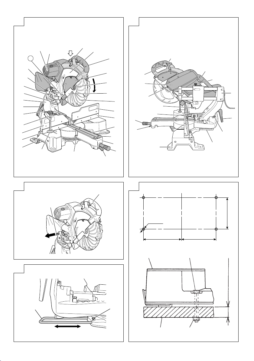
Handle
1
Lever (A)
2
Motor Head
3
Gear Case
4
Motor
5
Dust Bag
6
Hinge
7
Holder (A)
8
Indicator (For right bevel scale)
9
Laser Marker
0
Saw Blade
!
Vise Assembly
@
Fence (B)
#
Sub Fence (B)
$
Lever
%
Side Handle
^
Turntable
&
Table Insert
*
Indicator (For miter scale)
(
Fence (A)
)
Lower Guard
q
Washer (B)
w
Spindle Cover
e
Switch (For laser marker)
r
Trigger Switch
t
6 mm Flat Head Screw
y
Nameplate
u
Spindle Lock
i
Belt cover
o
Guard
p
Base
a
Holder
s
Set pin (A)
d
Clamp Lever
f
Indicator (For left bevel scale)
g
Slide Securing Knob
h
Adjuster (For laser marker)
j
Locking Pin
k
6 mm Bolt
l
Workpiece
;
Mounting hole (4 places)
z
8 mm Depth Adjustment Bolt
x
Auxiliary Board
c
6 mm Knob Bolt
v
(Optional accessory)
Holder (Optional accessory)
b
Steel Square
n
6 mm Wing Nut
m
(Optional accessory)
Height Adjustment Bolt 6 mm
,
(Optional accessory)
Base Surface
.
Stopper (Optional accessory)
/
6 mm Knob Bolt
¡
(Optional accessory)
Sub Fence (A)
™
6 mm Nut
£
Screw Holder
¢
Hex. socket set screw
∞
Vise Shaft
§
Duct
¶
Fence
•
6 mm Wing Bolt
ª
Vise Plate
º
Knob
⁄
Laser line
¤
Groove
‹
Bevel Scale
›
Miter Scale
fi
Crown molding Vise Ass’y
fl
(Optional accessory)
6 mm Wing Nut
‡
(Optional accessory)
Crown molding Stopper (L)
°
(Optional accessory)
Crown molding Stopper (R)
·
(Optional accessory)
Crown molding
‚
17 mm Box Wrench
Œ
10 mm Bolt
„
Washer (A)
´
Wear limit line
‰
6 mm Knob Bolt
ˇ
Right angle
Á
Dust extractor
¨
Hose (id 38 mm × 3 m long)
î
Adapter (Dust extractor's
Ø
standard accessory)
Joint (Optional accessory)
∏
9
Dust collection adapter
Å
(Optional accessory)
Hose band (Optional accessory)
Í
Marking (pre-marked)
Î
Line
Ï
Warning sign
˝
5 mm Machine screw
Ó
6 mm Depth adjustment bolt
Ô
Stopper holder
Bottom line of the groove
Ò
5 mm screw
Ú
Work bench
¸
8 mm Bolt
˛
8 mm Nut
Ç
25 mm thick bench
◊
8 mm Bolt (A)
ı
(Stopper for left 45° bevel angle)
8 mm Bolt (B)
˜
(Stopper for right 45° bevel angle)
8 mm Set Screw (Stopper for 0°)
Â
6 mm Machine screw
¯
Right angle cutting
˘
Left bevel angle cutting
¿
Right bevel angle cutting
101
Brush cap
102
No. of carbon brush
103
104
Guard (D)
Page 10

GENERAL OPERATIONAL
PRECAUTIONS
WARNING! When using electric tools, basic safety
precautions should always be followed to reduce the risk
of fi re, electric shock and personal injury, including the
following.
Read all these instructions before operating this product and
save these instructions.
For safe operations:
1. Keep work area clean. Cluttered areas and benches
invite injuries.
2. Consider work area environment. Do not expose power
tools to rain. Do not use power tools in damp or wet
locations. Keep work area well lit.
Do not use power tools where there is risk to cause fi re or
explosion.
3. Guard against electric shock. Avoid body contact with
earthed or grounded surfaces (e.g. pipes, radiators,
ranges, refrigerators).
4. Keep children and infi rm persons away. Do not let
visitors touch the tool or extension cord. All visitors
should be kept away from work area.
5. Store idle tools. When not in use, tools should be stored
in a dry, high or locked up place, out of reach of children
and infi rm persons.
6. Do not force the tool. It will do the job better and safer at
the rate for which it was intended.
7. Use the right tool. Do not force small tools or attachments
to do the job of a heavy duty tool. Do not use tools for
purposes not intended; for example, do not use circular
saw to cut tree limbs or logs.
8. Dress properly. Do not wear loose clothing or jewelry,
they can be caught in moving parts. Rubber gloves and
non-skid footwear are recommended when working
outdoors. Wear protecting hair covering to contain long
hair.
9. Use eye protection. Also use face or dust mask if the
cutting operation is dusty.
10. Connect dust extraction equipment.
Cutting operation by this compound miter saw may
produce considerable amount of dust from extraction
duct on fi xed guard.
(Dust material: Wood or Aluminium)
If devices are provided for the connection of dust
extraction and collection facilities ensure these are
connected and properly used.
11. Do not abuse the cord. Never carry the tool by the cord
or yank it to disconnect it from the receptacle. Keep the
cord away from heat, oil and sharp edges.
12. Secure work. Use clamps or a vise to hold the work. It
is safer than using your hand and it frees both hands to
operate tool.
13. Do not overreach. Keep proper footing and balance at all
times.
14. Maintain tools with care. Keep cutting tools sharp
and clean for better and safer performance. Follow
instructions for lubricating and changing accessories.
Inspect tool cords periodically and if damaged, have it
repaired by authorized service center. Inspect extension
cords periodically and replace, if damaged. Keep
handles dry, clean, and free from oil and grease.
15. Disconnect tools. When not in use, before servicing, and
when changing accessories such as blades, bits and
cutters.
16. Remove adjusting keys and wrenches. Form the habit
of checking to see that keys and adjusting wrenches are
removed from the tool before turning it on.
17. Avoid unintentional starting. Do not carry a plugged-in
tool with a fi nger on the switch. Ensure switch is off when
plugging in.
18. Use outdoor extension leads. When tool is used
outdoors, use only extension cords intended for outdoor
use.
19. Stay alert. Watch what you are doing. Use common
sense. Do not operate tool when you are tired.
20. Check damaged parts. Before further use of the tool, a
guard or other part that is damaged should be carefully
checked to determine that it will operate properly and
perform its intended function. Check for alignment of
moving parts, free running of moving parts, breakage of
parts, mounting and any other conditions that may aff ect
its operation. A guard or other part that is damaged
should be properly repaired or replaced by an authorized
service center unless otherwise indicated in this
handling instructions. Have defective switches replaced
by an authorized service center. Do not use the tool if the
switch does not turn it on and off .
21. Warning
The use of any accessory or attachment, other than
those recommended in this handling instructions, may
present a risk of personal injury.
22. Have your tool repaired by a qualifi ed person.
This electric tool is in accordance with the relevant safety
requirements. Repairs should only be carried out by
qualifi ed persons using original spare parts. Otherwise
this may result in considerable danger to the user.
PRECAUTIONS ON USING SLIDE
COMPOUND MITER SAW
1. Keep the fl oor area around the machine level. Well
maintained and free of loose materials e.g. chips and
cut-off s.
2. Provide adequate general or localized lighting.
3. Do not use power tools for applications other than those
specifi ed in the handling instructions.
4. Repairing must be done only by authorized service
facility. Manufacturer is not responsible for any damages
and injuries due to the repair by the unauthorized
persons as well as the mishandling of the tool.
5. To ensure the designed operational integrity of power
tools, do not remove installed covers or screws.
6. Do not touch movable parts or accessories unless the
power source has been disconnected.
7. Use your tool at lower input than specifi ed on the
nameplate; otherwise, the fi nish may be spoiled and
working effi ciency reduced due to motor overload.
8. Do not wipe plastic parts with solvent. Solvents such as
gasoline, thinner, benzine, carbon tetrachloride, alcohol,
may damage and crack plastic parts. Do not wipe them
with such solvent. Clean plastic parts with a soft cloth
lightly dampened with soapy water.
9. Use only original HiKOKI replacement parts.
10. This tool should only be disassembled for replacement
of carbon brushes.
11. The exploded assembly drawing on this handling
instructions should be used only for authorized service
facility.
12. Never cut ferrous metals or masonry.
13. Adequate general or localized lighting is provided.
Stock and fi nished workpieces are located close to the
operators normal working position.
14. Wear suitable personal protective equipment when
necessary, this could include:
Hearing protection to reduce the risk of induced hearing
loss.
Eye protection to reduce the risk of injuring an eye.
Respiratory protection to reduce the risk of inhalation of
harmful dust.
10
Page 11

Gloves for handling saw blades (saw blades shall be
carried in a holder wherever practicable) and rough
material.
15. The operator is adequately trained in the use, adjustment
and operation of the machine.
16. Refrain from removing any cut-off s or other parts of the
workpiece from the cutting area whilst the machine is
running and the saw head is not in the rest position.
17. Never use the slide compound miter saw with its lower
guard locked in the open position.
18. Ensure that the lower guard moves smoothly.
19. Do not use the saw without guards in position, in good
working order and properly maintained.
20. Use correctly sharpened saw blades. Observe the
maximum speed marked on the saw blade.
21. Do not use saw blades which are damaged or deformed.
22. Do not use saw blades manufactured from high speed
steel.
23. Use only saw blades recommended by HiKOKI.
24. The saw blades should be from 290 mm to 305 mm
external diameter ranges.
25. Select the correct saw blade for the material to be cut.
26. Never operate the slide compound miter saw with the
saw blade turned upward or to the side.
27. Ensure that the workpiece is free of foreign matter such
as nails.
28. Replace the table insert when worn.
29. Do not use the saw to cut other than aluminium, wood or
similar materials.
30. Do not use the saw to cut other materials than those
recommended by the manufacturer.
31. Blade replacement procedure, including the method for
repositioning and a warning that this must be carried out
correctly.
32. Connect the slide compound miter saw to a dust
collecting device when sawing wood.
33. Take care when slotting.
34. When transporting or carrying the tool, do not grasp the
holder. Grasp the handle instead of the holder.
35. Start cutting only after motor revolution reaches
maximum speed.
36. Promptly cut OFF the switch when abnormality observed.
37. Shut off power and wait for saw blade to stop before
servicing or adjusting tool.
38. During a miter or bevel cut the blade should not be lifted
until it has stopped rotation completely.
39. During slide cutting operation, the saw must be pushed
and slided away from the operator.
40. Take all the possibility of residual risks in cutting
operation into your consideration, such as the laser
radiation to your eyes, the inadvertent access to moving
parts on slide mechanical parts on machine and so on.
41. Ensure before each cut that the machine is stable.
Use only saw blades whose maximum permitted speed
is higher than the no-load speed of the power tool.
Do not replace the laser with a diff erent type.
42. Do not stand in a line with the saw blade In front of the
machine. Always stand aside of the saw blade. This
protects your body against possible kickback. Keep
hands, fi ngers and arms away from the rotating saw
blade.
Do not cross your arms when operating the tool arm.
43. If the saw blade should become jammed, switch the
machine off and hold the workpiece until the saw blade
comes to a complete stop. To prevent kickback, the
workpiece may not be moved until after the machine has
come to a complete stop.
Correct the cause for the jamming of the saw blade
before restarting the machine.
SYMBOLS
WARNING
The following show symbols used for the machine.
Be sure that you understand their meaning before
use.
C12RSH2: Slide Compound Miter Saw
Read all safety warnings and all instructions.
Always wear eye protection.
Always wear hearing protection.
11
Page 12

SPECIFICATIONS
Max.
sawing
dimension
Saw Blade Dimensions (oD × iD × Thickness) 305 mm × 25.4 mm × 2.3 mm
Miter Cutting Angle Right 0° – 57°, Left 0° – 45°
Bevel Cutting Angle Right 0° – 45°, Left 0° – 45°
Compound Cutting Angle
Voltage (by areas)*
Power Input* 1520 W
No-Load Speed 4000 /min
Machine Dimensions (Width × Depth × Height) 655 mm × 890 mm × 724 mm
Weight (Net) 27 kg
Laser Marker
Miter 0 0 Max. Height
Bevel Left 45° 0 Max. Height
Compound Left 45° Left 45° Max. Height
* Be sure to check the nameplate on product as it is subject to change by areas.
STANDARD ACCESSORIES
○ 305 mm TCT Saw blade (mounted on tool) ...................1
○ Dust bag .......................................................................1
○ 17 mm Box wrench .......................................................1
○ Vise Assembly ..............................................................1
○ Holder ...........................................................................1
○ Side Handle (mounted on tool) .....................................1
○ Sub Fence (mounted on tool) ........................................1
○ Washer (C) (Only For Australia) ....................................1
Standard accessories are subject to change without notice.
APPLICATION
Cutting various types of aluminium sash and wood.
PRIOR TO OPERATION
CAUTION
Make all necessary adjustments before inserting the
plug in the power source.
1. Power source
Ensure that the power source to be utilized conforms
to the power requirements specifi ed on the product
nameplate.
Do not use with direct current, or transformers such as
boosters. Doing so may result in damage or accidents.
Head Turntable Max. sawing dimension
0 Left 45°
0 Right 57° Max. Height
Right 45° 0 Max. Height
Left 45° Right 31° Max. Height
Right 45° Right 45° Max. Height
Right 45° Left 31°
Bevel (Left) 0° – 45° Miter (Left) 0° – 45°, (Right) 0° – 31°
Bevel (Right) 0° – 45° Miter (Right) 0° – 45°, (Left) 0° – 31°
Maximum output Po<0.4 mW Class 1M Laser Product
(Iambda) 650 nm
Laser medium Laser Diode
or
Right 45°
2. Power switch
Ensure that the power switch is in the OFF position. If the
plug is connected to a receptacle while the trigger switch
is in the ON position, the power tool will start operating
immediately, inviting serious accident.
3. Extention cord
When the work area is removed from the power source,
use an extension cord of suffi cient thickness and rated
capacity. The extension cord should be kept as short as
practicable.
4. Remove all packing materials attached or
connected to the tool before attempting to operate
it.
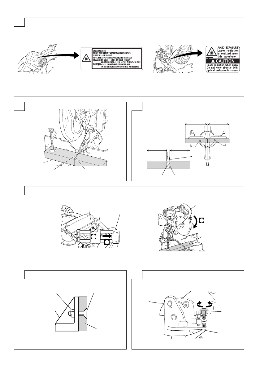
5. Releasing the locking pin (Fig. 3)
When the power tool is prepared for shipping, its main
parts are secured by a locking pin.
Move the handle slightly so that the locking pin can be
disengaged.
During transport, lock the locking pin into the gear case.
6. Attach the dust bag to the main unit (Fig. 1)
7. Installation (Fig. 4)
Ensure that the machine is always fi xed to bench.
Attach the power tool to a level, horizontal work bench.
Select 8 mm diameter bolts suitable in length for the
thickness of the work bench.
Bolt length should be at least 40 mm plus the thickness
of the work bench.
For example, use 8 mm × 65 mm bolts for a 25 mm thick
work bench.
Max. Width
Max. Height
Max. Width
Max. Width
Max. Width
Max. Width
Max. Width
Max. Width
Max. Width
Max. Height
Max. Width
230 V, 240 V
105 mm
312 mm
105 mm
220 mm
105 mm
170 mm
68 mm
312 mm
43 mm
312 mm
68 mm
220 mm
68 mm
265 mm
43 mm
220 mm
43 mm
265 mm
12
Page 13

8. Base holder adjustment (Fig. 5)
Loosen the 6 mm bolt with the supplied 10 mm box
wrench. Adjust the base holder until its bottom surface
contacts the bench or the fl oor surface.
After adjustment, fi rmly tighten the 6 mm bolt.
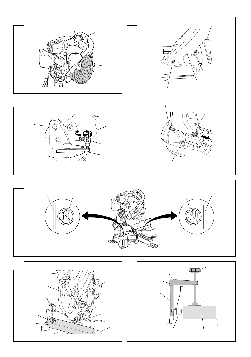
9. Check to see that the lower guard operates
smoothly
CAUTION
○ This slide compound miter saw is equipped with a saw
head lock as safety device.
○ To lower the saw head to cut, the lock must be released
by pressing the lever (A) with your thumb.
(1) When you push down the handle while pushing the
lever (A), check that the lower guard revolves smoothly
(Fig. 6).
(2) Next, check that the lower guard returns to the original
position when the handle is raised.
10. Oblique angle
Before the power tool is shipped from the factory, it is
adjusted for 0°, right angle, left 45° bevel cutting angle
and right 45° bevel cutting angle with the 8 mm set
screw, 8 mm bolt (A) and 8 mm bolt (B).
When changing the adjustment, change the height of
the 8 mm set screw, 8 mm bolt (A), or 8 mm bolt (B) by
turning them.
When changing the bevel angle to the right 45°, pull the
set pin (A) on the direction shown in Fig. 7-b and incline
the motor head to the right.
When adjusting the motor head to 0°, always return the
set pin (A) to its initial position as shown in Fig. 7-b.
11. Checking the saw blade lower limit position
Check that the saw blade can be lowered 9 mm to
10 mm below the table insert.
When you replace a saw blade with a new one, adjust
the lower limit position so that the saw blade will not cut
the turntable or complete cutting cannot be done.
To adjust the lower limit position of the saw blade, follow
the procedure (1) indicated below. (Fig. 8)
Furthermore, when changing the position of a 8 mm
depth adjustment bolt that serves as a lower limit position
stopper of the saw blade.
(1) Turn the 8 mm depth adjustment bolt, change the height
where the bolt head and the hinge contacts, and adjust
the lower limit position of the saw blade.
NOTE
Confi rm that the saw blade is adjusted so that it will not
cut into the turntable.
PRIOR TO CUTTING
1. Cutting a groove on the guard
Holder (A) has a guard (see Fig. 10) into which a groove
must be cut when using the tool for the fi rst time. Loosen
the 6 mm knob bolt to retract the guard slightly.
After placing a suitable wooden piece to sit on the
fence and the table surfaces, fi x it with the vise. Slide
the motor head backwards to the end. Then tighten the
slide securing knob. After the switch has been turned on
and the saw blade has reached maximum speed, slowly
lower the handle to cut a groove on the guard. (See
Fig. 20)
CAUTION
Do not cut the groove too quickly; otherwise the guard
might become damaged.
Do not use slide cutting for grooving tasks.
PRACTICAL APPLICATIONS
WARNING
○ To avoid personal injury, never remove or place a
workpiece on the table while the tool is being operated.
○ Never place your limbs inside of the line next to warning
sign while the tool is being operated (see Fig. 9). This
may cause hazardous conditions.
CAUTION
○ It is dangerous to remove or install the workpiece while
the saw blade is turning.
○ When sawing, clean off the shavings from the turntable.
○ If the shavings accumulate too much, the saw blade from
the cutting material will be exposed. Never subject your
hand or anything else to go near the exposed blade.
1. Switch operation
Pulling the trigger turns the switch on. Releasing the
trigger turns the switch off .
2. Using the Vise Assembly (Standard accessory)
(Fig. 11)
(1) The vise assembly can be mounted on either the left
fence {Fence (B)} or the right fence {Fence (A)}.
(2) The screw holder can be raised or lowered according to
the height of the workpiece.
(3) Turn the upper knob and securely fi x the workpiece in
position.
WARNING
Always fi rmly clamp or vise to secure the workpiece to
the fence; otherwise the workpiece might be thrust from
the table and cause bodily harm.
CAUTION
Always confi rm that the motor head does not contact the
vise assembly when it is lowered for cutting. If there is
any danger that it may do so, move the vise assembly to
a position where it will not contact the saw blade.
3. Positioning the table insert (Fig. 12)
Table inserts are installed on the turntable. When
shipping the tool from the factory, the table inserts are
so fi xed that the saw blade does not contact them. The
burr of the bottom surface of the workpiece is remarkably
reduced, if the table insert is fi xed so that the gap
between the side surface of the table insert and the saw
blade will be minimum. Before using the tool, eliminate
this gap in accordance with the following procedure.
(1) Right angle cutting
Loosen the three 5 mm machine screws, then secure
the left side table insert and temporarily tighten the 5 mm
machine screws of both ends. Then fi x a workpiece
(about 200 mm wide) with the vise assembly and cut it
off . After aligning the cutting surface with the edge of the
table insert, securely tighten the 5 mm machine screws
of both ends. Remove the workpiece and securely
tighten the 5 mm center machine screw. Adjust the right
hand table insert in the same way.
(2) Left and right bevel angle cutting
Adjust the table insert in the manner same procedure for
right angle cutting.
CAUTION
After adjusting the table insert for right angle cutting, the
table insert will be cut to some extent if it is used for bevel
angle cutting.
When bevel cutting operation is required, adjust the
table insert for bevel angle cutting.
4. Lower limit position of saw blade when cutting a
large workpiece
NOTE
When cutting a workpiece exceeding 105 mm in height
in right-angle cutting or 68 mm in left bevel angle cutting
or 43 mm in right bevel angle cutting, adjust the lower
limit position so that the base of the motor head (see
Fig. 13) will not come in contact with the workpiece.
13
Page 14

To adjust the lower limit position of the saw blade, follow
the procedure (1) shown in Fig. 13.
(1) Lower the motor head, and turn the 8 mm depth
adjustment bolt and make adjustments so that there can
be a clearance of 2 mm to 3 mm between the lower limit
position of the motor head and the top of the workpiece
at the saw blade's lower limit position where the head of
the 8 mm depth adjustment bolt contacts the hinge.
5. Confi rmation for use of sub fence (A) (Fig. 14)
WARNING
When right angle cutting, loosen the 6 mm wing bolt,
then slide the sub fence (A) outward and remove it.
Failure to do so may result in the main body or saw blade
coming into contact with the sub fence (A) and causing
injury.
This power tool is equipped with a sub fence (A).
In the case of direct angle cutting and left bevel angle
cutting, use the sub fence (A). Then, you can realize
stable cutting of the material with a wide back face.
When right angle cutting, loosen the 6 mm wing bolt,
then slide the sub fence (A) outward and remove it, as
shown in Fig. 14.
6. Confi rmation for use of sub fence (B) (Fig. 14)
WARNING
When left angle cutting, loosen the 6 mm wing bolt, then
slide the sub fence (B) outward. Failure to do so may
result in the main body or saw blade coming into contact
with the sub fence (B) and causing injury.
This power tool is equipped with a sub fence (B). In the
case of direct angle cutting and right bevel angle cutting,
use the sub fence (B). Then, you can realize stable
cutting of the material with a wide back face. When left
angle cutting, loosen the 6 mm wing bolt, then slide the
sub fence (B) outward, as shown in Fig. 14.
7. Using an ink line (Adjusting the guard)
(1) Right angle cutting
Loosen the 6 mm knob bolt and contact the tip of the
guard with the workpiece.
Aligning the ink line on the workpiece with the groove of
the guard, the workpiece is cut on the ink line.
(2) Miter cutting and compound cutting (Miter cutting +
bevel cutting)
Upon lowering the motor section, the lower guard is
raised and the saw blade appears.
Align the ink line with the saw blade.
CAUTION
In some arrangements when the turntable is rotated, the
guard projects from the fence surface. Loosen the 6 mm
knob bolt and push the guard to the retracted position.
Never lift the lower guard while the saw blade is rotating.
When cutting at an angle of 45° to the right or more,
please slide the guard to the rear.
The guard and sub-fence (A) and sub-fence (B) will not
only make contact and adversely aff ect cutting accuracy,
this could also result in damage to the guard.
8. Position adjustment of laser line
Ink lining can be easily made on this tool to the laser
marker. A switch lights up the laser marker (Fig. 15).
Depending upon your cutting choice, the laser line can
be aligned with the left side of the cutting width (saw
blade) or the ink line on the right side.
The laser line is adjusted to the width of the saw blade at
the time of factory shipment. Adjust the positions of the
saw blade and the laser line taking the following steps to
suit the use of your choice.
(1) Light up the laser marker and make a groove of about
5 mm deep on the workpiece that is about 20 mm in
height and 150 mm in width. Hold the grooved workpiece
by vise as it is and do not move it. For grooving work,
refer to “20. Groove cutting procedures”.
(2) Then, turn the adjuster and shift the laser line. (If you turn
the adjuster clockwise, the laser line will shift to the right
and if you turn it counterclockwise, the laser line will shift
to the left.) When you work with the ink line aligned with
the left side of the saw blade, align the laser line with the
left end of the groove (Fig. 16). When you align it with
the right side of the saw blade, align the laser line with
the right side of the groove.
(3) After adjusting the position of the laser line, draw a right-
angle ink line on the workpiece and align the ink line
with the laser line. When aligning the ink line, slide the
workpiece little by little and secure it by vise at a position
where the laser line overlaps with the ink line. Work on
the grooving again and check the position of the laser
line. If you wish to change the laser line’s position, make
adjustments again following the steps from (1) to (3).
WARNING
○ Make sure before plugging the power plug into the
receptacle that the main body and the laser marker are
turned off .
○ Exercise utmost caution in handling a switch trigger for
the position adjustment of the laser line, as the power
plug is plugged into the receptacle during operation.
If the switch trigger is pulled inadvertently, the saw blade
can rotate and result in unexpected accidents.
○ Do not remove the laser marker to be used for other
purposes.
CAUTION (Fig. 17)
○ Laser radiation - Do not stare into beam.
○ Laser radiation on work table. Do not stare into beam. If
your eye is exposed directly to the laser beam, it can be
hurt.
○ Do not dismantle it.
○ Do not give strong impact to the laser marker (main body
of tool); otherwise, the position of a laser line can go out
of order, resulting in the damage of the laser marker as
well as a shortened service life.
○ Keep the laser marker lit only during a cutting operation.
Prolonged lighting of the laser marker can result in a
shortened service life.
○ Use of controls or adjustments or performance of
procedures other than those specifi ed herein may result
in hazardous radiation exposure.
NOTE
○ Perform cutting by overlapping the ink line with the laser
line.
○
When the ink line and the laser line are overlapped, the
strength and weakness of light will change, resulting in a
stable cutting operation because you can easily discern the
conformity of lines. This ensures the minimum cutting errors.
○ In outdoor or near-the-window operations, it may
become diffi cult to observe the laser line due to the
sunlight. Under such circumstances, move to a place
that is not directly under the sunlight and engage in the
operation.
○ Check and make sure on a periodic basis if the position
of the laser line is in order. As regards the checking
method, draw a right-angle ink line on the workpiece with
the height of about 20 mm and the width of 150 mm, and
check that the laser line is in line with the ink line [The
deviation between the ink line and the laser line should
be less than the ink line width (0.5 mm)]. (Fig. 18)
9. Cutting operation
(1) As shown in Fig. 19 the width of the saw blade is the
width of the cut. Therefore, slide the workpiece to the
right (viewed from the operator’s position) when length
is desired, or to the left when length is desired.
If a laser marker is used, align the laser line with the left
side of the saw blade, and then align the ink line with the
laser line.
14
Page 15

(2) After turning on the switch and checking that the saw
blade is rotating at maximum speed, slowly push down
the handle while holding down the lever (A) and bring the
saw blade in the vicinity of the material to be cut.
(3) Once the saw blade contacts the workpiece, push the
handle down gradually to cut into the workpiece.
(4) After cutting the workpiece to the desired depth, turn the
power tool OFF and let the saw blade stop completely
before raising the handle from the workpiece to return it
to the full retract position.
CAUTION
○ For maximum dimensions for cutting, refer to
“SPECIFICATIONS” table.
○
Increased pressure on the handle will not increase the cutting
speed. On the contrary, too much pressure may result in
overload of the motor and/or decreased cutting effi ciency.
○ Confi rm that the trigger switch is turned OFF and the
power plug has been removed from the receptacle
whenever the tool is not in use.
○ Always turn the power off and let the saw blade stop
completely before raising the handle from the workpiece.
If the handle is raised while the saw blade is still rotating,
the cut-off piece may become jammed against the saw
blade causing fragments to scatter about dangerously.
○ Every time one cutting of deep-cutting operation is
fi nished, turn the switch off , and check that the saw
blade has stopped. Then raise the handle, and return it
to the full retract position.
○ Be absolutely sure to remove the cut material from the
top of the turntable, and then proceed to the next step.
○ Continued cutting operation can result in overload of the
motor. Touch the motor and if it's hot, stop your cutting
operation once and rest for 10 minutes or so, and then
restart your cutting operation.
10. Cutting narrow workpieces (Press cutting) (Fig. 20)
Slide the hinge down to holder (A), then tighten the
slide securing knob (Fig. 2). Lower the handle to cut
the workpiece. Using the power tool this way will permit
cutting of workpieces of up to 105 mm square.
11. Cutting large workpieces (Fig. 21, 22)
There may be case when a complete cutting cannot be
done depending on the height of workpiece. In this case,
mount an auxiliary board with the 6 mm fl at head screws
and the 6 mm nuts using the 7 mm holes on the fence
surface (two holes on each side). (Fig. 21)
NOTE
When cutting a workpiece exceeding 105 mm in height
in right-angle cutting or 68 mm in left bevel angle cutting
or 42 mm in right bevel angle cutting, adjust the lower
limit position so that the base of the motor head will not
come in contact with the workpiece.
To adjust the lower limit position of the saw blade, follow the
procedure (1) shown in Fig. 22.
(1) Lower the motor head, and turn the 8 mm depth
adjustment bolt and make adjustments so that there can
be a clearance of 2 mm to 3 mm between the lower limit
position of the motor head and the top of the workpiece
at the saw blade's lower limit position where the head of
the 8 mm depth adjustment bolt contacts the hinge.
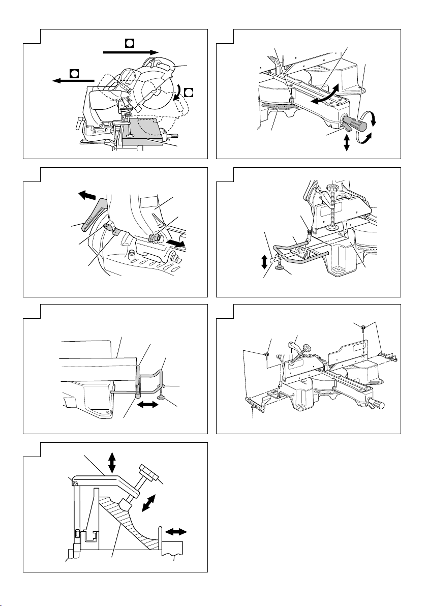
12. Cutting wide workpieces (Slide cutting) (Fig. 23)
(1) Workpieces up to 105 mm high and 312 mm wide:
Loosen the slide securing knob (A) (Fig. 2), grip the
handle and slide the saw blade forward.
Then press down on the handle and slide the saw blade
back to cut the workpiece. This facilitates cutting of
workpieces of up to 105 mm in height and 312 mm in
width.
CAUTION
○ If the handle is pressed down with excessive or lateral
force, the saw blade may vibrate during the cutting
operation and cause unwanted cutting marks on the
workpiece, thus reducing the quality of the cut.
Accordingly, press the handle down gently and carefully.
○ In slide cutting, gently push the handle back (rearwards)
in a single, smooth operation. Stopping the handle
movement during the cut will cause unwanted cutting
marks on the workpiece.
WARNING
○ For slide cutting, follow the procedures.
Forward slide cutting (toward the operator) is very
dangerous because the saw blade could kick upward
from the workpiece. Therefore, always slide the handle
away from the operator.
○ Always return the carriage to the full rear position after
each crosscut operation in order to reduce the risk of
injury.
○ Never put your hand on the side handle during the
cutting operation because the saw blade comes close to
the side handle when the motor head is lowered.
13. Miter cutting procedures
(1) Loosen the side handle and pull up the lever for angle
stoppers. Then, adjust the turntable until the indicator
aligns with desired setting on the miter scale (Fig. 24).
(2) Re-tighten the side handle to secure the turntable in the
desired position.
(3) The miter scale indicates both the cutting angle on the
angle scale and the gradient on the grade scale.
(4) The gradient, which is the ratio of the height to the base
of the triangular section to be removed, may be used
for setting the miter scale instead of the cutting angle, if
desired.
Therefore, to cut a workpiece at a grade of 2/10, set the
indicator to position.
NOTE
○ Positive stops are provided at the right and left of the 0°
center setting, at 15°, 22.5°, 30° and 45° settings.
Check that the miter scale and the tip of the indicator are
properly aligned.
○ Operation of the saw with the miter scale and indicator
out of alignment, or with the side handle not properly
tightened, will result in poor cutting precision.
14. Bevel cutting procedures (Fig. 25)
(1) Loosen the clamp lever and bevel the saw blade to the
left or to the right. When tilting the motor head to the right
pull the set pin (A) towards the rear.
The clamp lever adopts a latchet system. When
contacting the work bench and the main body, pull
the clamp lever in the direction of the arrow mark as
illustrated in Fig. 25, and change the direction of the
clamp lever.
(2) Adjust the bevel angle to the desired setting while
watching the bevel angle scale and indicator, then
secure the clamp lever.
WARNING
When the workpiece is secured on the left or right side
of the blade, the short cut-off
on the right or left side of the saw blade. Always turn the
power off and let the saw blade stop completely before
raising the handle from the workpiece.
If the handle is raised while the saw blade is still rotating,
the cut-off piece may become jammed against the saw
blade causing fragments to scatter about dangerously.
When stopping the bevel cutting operation halfway, start
cutting after pulling back the motor head to the initial
position.
Starting from halfway, without pulling back, causes the
lower guard to be caught in the cutting groove of the
workpiece and to contact the saw blade.
15. Compound cutting procedures
Compound cutting can be performed by following the
instructions in 13 and 14 above. For maximum dimensions
for compound cutting, refer to “SPECIFICATIONS” table.
15
portion will come to rest
Page 16

CAUTION
Always secure the workpiece with the right or left
hand and cut it by sliding the round portion of the saw
backwards with the left hand.
It is very dangerous to rotate the turntable to the left
during compound cutting because the saw blade may
come into contact with the hand that is securing the
workpiece.
In case of compound cutting (angle + bevel) by left
bevel, slide the sub-fence (B) outward, and engage in
the cutting operation.
In case of compound cutting (angle + bevel) by right
bevel, remove the sub-fence (A), and engage in the
cutting operation.
16. Cutting long materials
When cutting long materials, use an auxiliary platform
which is the same height as the holder (optional
accessory) and base of the special auxiliary equipment.
Capacity: wooden material (W × H × L)
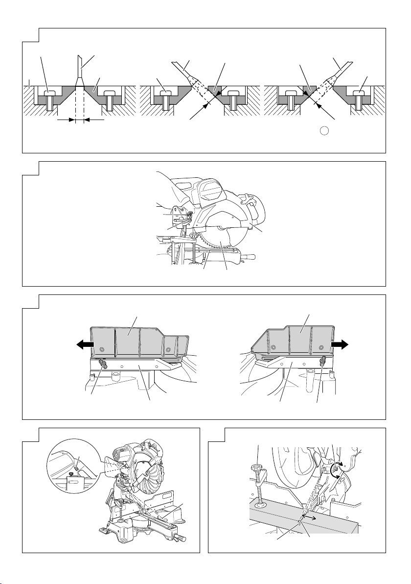
17. Installing the holders … (Optional accessory)
The holders help keep longer workpieces stable and in
place during the cutting operation.
(1) As indicated in Fig. 26, use a steel square for aligning
the upper edge of the holders with the base surface.
Loosen the 6 mm wing nut. Turn a height adjustment bolt
6 mm, and adjust the height of the holder.
(2) After adjustment, fi rmly tighten the 6 mm wing nut and
fasten the holder with the 6 mm knob bolt (optional
accessory). If the length of Height Adjustment Bolt 6 mm
is insuffi cient, spread a thin plate beneath. Make sure the
end of Height Adjustment Bolt 6 mm does not protrude
from the holder.
CAUTION
○ When transporting or carrying the tool, do not grasp the
holder.
○ There is the danger of the holder slipping out of the base.
Grasp the handle instead of the holder.
18. Stopper for precision cutting … (Stopper and
holder are optional accessory)
The stopper facilitates continuous precision cutting in
lengths of 285 mm to 450 mm.
To install the stopper, attach it to the holder with the
6 mm knob bolt as shown in Fig. 27.
19. Confi rmation for use Crown molding vise, Crown
molding Stopper (L) and (R) (Optional accessory)
(1) Crown molding Stopper (L) and (R) (optional
accessories) allow easier cuts of crown molding without
tilting the saw blade. lnstall them in the base both-sides
side to be shown in Fig. 28. After inserting tighten the
6 mm knob bolts to secure the Crown molding Stoppers.
(2) The crown molding vise (B) (Optional accessory) can be
mounted on either the left fence (Fence (B)) or the right
fence (Fence (A)). lt can unite with the slope of the crown
molding and vice can be pressed down.
Then turn the upper knob, as necessary, to securely
attach the crown molding in position. To raise or lower the
vise assembly, fi rst loosen the hex. socket set screw.
After adjusting the height, fi rmly tighten the 6 mm wing
bolt; then turn the upper knob, as necessary, to securely
attach the the crown molding in position (Fig. 29).
Position crown molding with its WALL CONTACT EDGE
against the guide fence and its CEILING CONTACT
EDGE against the Crown molding Stoppers as shown in
Fig. 29. Adjust the Crown molding Stoppers according
to the size of the crown molding.
Tighten the 6 mm wing bolt to secure the Crown molding
Stoppers. Refer to the lower table for the miter angle.
Use the sub fence (A) to secure the crown molding more
fi rmly (Fig. 11).
300 mm × 43 mm × 1300 mm, or
180 mm × 25 mm × 2000 mm
WARNING
Always fi rmly clamp or vise to secure the crown molding
to the fence; otherwise the crown molding might be
thrust from the table and cause bodily harm.
Do not bevel cutting. The main body or saw blade may
contact the sub fence, resulting in an injury.
CAUTION
Always confi rm that the motor head does not contact the
crown molding vise ass’y when it is lowered for cutting.
If there is any danger that it may do so, loosen the hex.
socket set screw and move the crown molding vise ass’y
to a position where it will not contact the saw blade.
20. Groove cutting procedures
Grooves in the workpiece can be cut by adjusting the
6 mm depth adjustment bolt (Fig. 30).
(1) Turn the stopper holder on the direction shown in
Fig. 31.
Lower the motor head, and turn the 6 mm depth
adjustment bolt by hand. (Where the head of the 6 mm
depth adjustment bolt contacts the hinge.)
(2) Adjust to the desired cutting depth by setting the
distance between the saw blade and the surface of the
base (Fig. 30).
NOTE
When cutting a single groove at either end of the
workpiece, remove the unneeded portion with a chisel.
21. Using the dust bag (Standard accessory) (Fig. 32)
(1) Connect the dust bag with the duct of power tool.
(2) When the dust bag has become full of sawdust, dust will
be blown out of the dust bag when the saw blade rotates.
Check the dust bag periodically and empty it before it
becomes full.
(3) During bevel and compound cutting, attach the dust bag
at the right angle to the base surface.
22. Connecting the dust extractor (Sold separately)
(Fig. 33)
Do not inhale the harmful dusts generated in cutting
operation.
The dust can endanger the health of yourself and
bystanders.
Use of dust extractor can reduce dust related hazards.
By connecting with dust extractor through adapter,
joint and dust collection adapter, most of dust can be
collected.
Connect the dust extractor with adapter.
(1) Connect in order of hose (id 38 mm × 3 m long) and
adapter (Dust extractor’s Standard accessory) joint
(Optional accessory) and dust collection adapter
(Optional accessory) with the duct of power tool.
Connection is done by pressing in the direction of the
arrow. (Fig. 33)
The dust collection adapter (Optional accessory) is fi xed
to the duct by a hose band. (Optional accessory)
MOUNTING AND DISMOUNTING SAW
BLADE
WARNING
To prevent an accident or personal injury, always turn off
the trigger switch and disconnect the power plug from
the receptacle before removing or installing a saw blade.
1. Mounting the saw blade (Fig. 34)
(1) Use the Phillips screwdriver to loosen the 5 mm screw
fastening the spindle cover and then turn the spindle
cover.
(2) Press in spindle lock and loosen 10 mm bolt with 17 mm
wrench (standard accessory).
Since the 10 mm bolt is left-hand threaded, loosen by
turning it to the right.
16
Page 17

NOTE
If the spindle lock cannot be easily pressed in to lock
the spindle, turn the 10 mm bolt with 17 mm wrench
(standard accessory) while applying pressure on the
spindle lock.
The saw blade spindle is locked when the spindle lock is
pressed inward.
(3) Remove the bolt and washer (D)
(4) Lift the lower guard and mount the saw blade.
WARNING
When mounting the saw blade, confi rm that the rotation
indicator mark on the saw blade and the rotation direction
of the spindle cover (Fig. 1) are properly matched.
(5) Thoroughly clean washer (B) and the 10 mm bolt, and
install them onto the saw blade spindle.
(6) Press in the spindle lock and tighten the 10 mm bolt by
turning it to the left by standard accessories (17 mm
wrench).
(7) Rotate the spindle cover unitl hook in spindle cover is in
the original position. Then tighten the 6 mm bolt.
CAUTION
○ A dust guide is installed inside behind the hinge. When
removing or installing the saw blade, do not make
contact with the dust guide. Contact may break or chip
saw blade tips.
○ Tighten the 10 mm bolt so it does not come loose during
operation.
○ Confi rm the 10 mm bolt has been properly tightened
before the power tool is started.
○ Confi rm that the lower guard has closed position.
2. Dismounting the saw blade
Dismount the saw blade by reversing the mounting
procedures described in paragraph 1 above.
The saw blade can easily be removed after lifting the
lower guard.
CAUTION
Never attempt to install saw blades except
305 mm in diameter.
MAINTENANCE AND INSPECTION
WARNING
To avoid an accident or personal injury, always confi rm
the trigger switch is turned OFF and that the power
plug has been disconnected from the receptacle before
performing any maintenance or inspection of this tool.
Report to qualifi ed person as soon as possible, if you
discover the fault of machine including guards or blade
saw.
1. Inspecting the saw blade
Always replace the saw blade immediately upon the fi rst
sign of deterioration or damage.
A damaged saw blade can cause personal injury and
a worn saw blade can cause ineff ective operation and
possible overload to the motor.
CAUTION
Never use a dull saw blade. When a saw blade is dull,
its resistance to the hand pressure applied by the tool
handle tends to increase, making it unsafe to operate the
power tool.
2. Inspecting the mounting screws
Regularly inspect all mounting screws and ensure that
they are properly tightened. Should any of the screws
be loose, re-tighten them immediately. Failure to do so
could result in serious hazard.
3. Inspecting the carbon brushes (Fig. 35)
The motor employs carbon brushes which are consumable
parts. Since an excessively worn carbon brush can result
in motor trouble, replace the carbon brushes with new
ones having the same carbon brush No. shown in the
fi gure when it becomes worn to or near the “wear limit”. In
addition, always keep carbon brushes clean and ensure
that they slide freely within the brush holders.
17
4. Replacing a carbon brushes (Fig. 35)
Disassemble the brush cap with a slotted-head
screwdriver. The carbon brushes can then be easily
removed.
5. Maintenance of the motor
The motor unit winding is the very “heart” of the power
tool. Exercise due care to ensure the winding does not
become damaged and/or wet with oil or water.
6. Inspecting the lower guard for proper operation
Before each use of the tool, test the lower guard (Fig. 6)
to assure that it is in good condition and that it moves
smoothly.
Never use the tool unless the lower guard operates
properly and it is in good mechanical condition.
7. Storage
After operation of the tool has been completed, check
that the following has been performed:
(1) Trigger switch is in OFF position,
(2) Power plug has been removed from the receptacle,
When the tool is not in use, keep it stored in a dry place
out of the reach of children.
8. Replacement of guard
After long-term use, the blade slot in the guard may
widen and require replacement. If the blade slot should
widen, replace the guard with a new one (Fig. 33). After
replacing, make a groove on it. Refer to “PRIOR TO
CUTTING 1. Cutting a groove on the guard” on page 13.
9. Lubrication
Lubricate the following sliding surfaces once a month
to keep the power tool in good operating condition for a
long time.
Use of machine oil is recommended.
Oil supply points:
* Rotary portion of hinge
* Rotary portion of holder (A)
* Rotary portion of vise assembly
10. Cleaning
Periodically remove chips and other waste material
from the surface of the power tool with a damp, soapy
cloth. To avoid a malfunction of the motor, protect it from
contact with oil or water.
If the laser line becomes invisible due to chips and the
like adhered onto the window of the laser marker's light-
emitting section, wipe and clean the window with a dry
cloth or a soft cloth moistened with soapy water, etc.
SELECTING ACCESSORIES
The accessories of this machine are listed on page 19.
CAUTION
Repair, modifi cation and inspection of HiKOKI Power
Tools must be carried out by a HiKOKI Authorized
Service Center.
Especially laser device should be maintained by the
authorized agent by laser manufacturer.
Always assign the repair of laser device to HiKOKI
Authorized Service Center.
In the operation and maintenance of power tools, the
safety regulations and standards prescribed in each
country must be observed.
NOTE
Due to HiKOKI’s continuing program of research and
development the specifi cations herein are subject to change
without prior notice.
Page 18

339652
988101
328326
324452
328520
322955
333732
998834
960017 960017
321390
301806
339730
339625
307956
307956
996722
339626
322047
304043
996722
321390
339661
965841
322283 230V: 999065
301806
339731
339662
322677
974561
949404
321549
949313
949556
322047
324412
339624
996247
339660
324464
18
Page 19

19
Page 20

Shinagawa Intercity Tower A, 15-1, Konan 2-chome,
Minato-ku, Tokyo, Japan
Code No. C99715112 F
Printed in China
806
 Loading...