

Page 1

Slide Compound Miter Saw
Model C 12LSH • C 12RSH
Handling instructions
Note:
Before using this Electric Power Tool, carefully read through these
HANDLING INSTRUCTIONS to ensure efficient, safe operation. It is
recommended that these INSTRUCTIONS be kept readily available
as an important reference when using this power tool.
Page 2

GENERAL OPERATIONAL PRECAUTIONS
WARNING! When using electric tools, basic safety
precautions should always be followed to reduce the risk
of fire, electric shock and personal injury, including the
following.
Read all these instructions before operating this product
and save these instructions.
For safe operations:
1. Keep work area clean. Cluttered areas and benches
invite injuries.
2. Consider work area environment. Do not expose
power tools to rain. Do not use power tools in damp
or wet locations. Keep work area well lit.
Do not use power tools where there is risk to cause
fire or explosion.
3. Guard against electric shock. Avoid body contact
with earthed or grounded surfaces (e.g. pipes,
radiators, ranges, refrigerators).
4. Keep children and infirm persons away. Do not let
visitors touch the tool or extension cord. All visitors
should be kept away from work area.
5. Store idle tools. When not in use, tools should be
stored in a dry, high or locked up place, out of reach
of children and infirm persons.
6. Do not force the tool. It will do the job better and
safer at the rate for which it was intended.
7. Use the right tool. Do not force small tools or
attachments to do the job of a heavy duty tool. Do
not use tools for purposes not intended; for example,
do not use circular saw to cut tree limbs or logs.
8. Dress properly. Do not wear loose clothing or
jewelry, they can be caught in moving parts. Rubber
gloves and non-skid footwear are recommended
when working outdoors. Wear protecting hair
covering to contain long hair.
9. Use eye protection. Also use face or dust mask if
the cutting operation is dusty.
10. Connect dust extraction equipment.
Cutting operation by this slide compound miter saw
may produce considerable amount of dust from
extraction duct on fixed guard.
(Dust material: Wood or Aluminium)
If devices are provided for the connection of dust
extraction and collection facilities ensure these are
connected and properly used.
11. Do not abuse the cord. Never carry the tool by the
cord or yank it to disconnect it from the receptacle.
Keep the cord away from heat, oil and sharp edges.
12. Secure work. Use clamps or a vise to hold the work.
It is safer than using your hand and it frees both
hands to operate tool.
13. Do not overreach. Keep proper footing and balance
at all times.
14. Maintain tools with care. Keep cutting tools sharp
and clean for better and safer performance. Follow
instructions for lubrication and changing
accessories. Inspect tool cords periodically and if
damaged, have it repaired by authorized service
center. Inspect extension cords periodically and
replace, if damaged. Keep handles dry, clean, and
free from oil and grease.
15. Disconnect tools. When not in use, before servicing,
and when changing accessories such as blades, bits
and cutters.
16. Remove adjusting keys and wrenches. Form the
habit of checking to see that keys and adjusting
wrenches are removed from the tool before turning
it on.
17. Avoid unintentional starting. Do not carry a pluggedin tool with a finger on the switch. Ensure switch is
off when plugging in.
18. Use outdoor extension leads. When tool is used
outdoors, use only extension cords intended for
outdoor use.
19. Stay alert. Watch what you are doing. Use common
sense. Do not operate tool when you are tired.
20. Check damaged parts. Before further use of the tool,
a guard or other part that is damaged should be
carefully checked to determine that it will operate
properly and perform its intended function. Check
for alignment of moving parts, free running of
moving parts, breakage of parts, mounting and any
other conditions that may affect its operation. A
guard or other part that is damaged should be
properly repaired or replaced by an authorized
service center unless otherwise indicated in this
handling instructions. Have defective switches
replaced by an authorized service center. Do not use
the tool if the switch does not turn it on and off.
21. Warning
The use of any accessory or attachment, other than
those recommended in this handling instructions,
may present a risk of personal injury.
22. Have your tool repaired by a qualified person.
This electric tool is in accordance with the relevant
safety requirements. Repairs should only be carried
out by qualified persons using original spare parts.
Otherwise this may result in considerable danger
to the user.
PRECAUTIONS ON USING SLIDE COMPOUND
MITER SAW
1. Keep the floor area around the machine level. Well
maintained and free of loose materials e.g. chips
and cut-offs.
2. Provide adequate general or localized lighting.
3. Do not use power tools for applications other than
those specified in the handling instructions.
4. Repairing must be done only by authorized service
facility. Manufacturer is not responsible for any
damages and injuries due to the repair by the
unauthorized persons as well as the mishandling of
the tool.
5. To ensure the designed operational integrity of
power tools, do not remove installed covers or
screws.
6. Do not touch movable parts or accessories unless
the power source has been disconnected.
7. Use your tool at lower input than specified on the
nameplate; otherwise, the finish may be spoiled and
working efficiency reduced due to motor overload.
8. Do not wipe plastic parts with solvent. Solvents such
as gasoline, thinner, benzine, carbon tetrachloride,
alcohol, may damage and crack plastic parts. Do not
wipe them with such solvent. Clean plastic parts with
a soft cloth lightly dampened with soapy water.
9. Use only original HITACHI replacement parts.
10. This tool should only be disassembled for
replacement of carbon brushes.
2
Page 3

11. The exploded assembly drawing on this handling
instructions should be used only for authorized
service facility.
12. Never cut ferrous metals or masonry.
13. Adequate general or localized lighting is provided.
Stock and finished workpieces are located close to
the operators normal working position.
14. Wear suitable personal protective equipment when
necessary, this could include:
Hearing protection to reduce the risk of induced
hearing loss.
Eye protection to reduce the risk of injuring an eye.
Respiratory protection to reduce the risk of
inhalation of harmful dust.
Gloves for handling saw blades (saw blades shall
be carried in a holder wherever practicable) and
rough material.
15. The operator is adequately trained in the use,
adjustment and operation of the machine.
16. Refrain from removing any cut-offs or other parts
of the workpiece from the cutting area whilst the
machine is running and the saw head is not in the
rest position.
17. Never use the slide compound miter saw with its
lower guard locked in the open position.
18. Ensure that the lower guard moves smoothly.
19. Do not use the saw without guards in position, in
good working order and properly maintained.
20. Use correctly sharpened saw blades. Observe the
maximum speed marked on the saw blade.
21. Do not use saw blades which are damaged or
deformed.
22. Do not use saw blades manufactured from high
speed steel.
23. Use only saw blades recommended by HITACHI.
24. The saw blades should be from 290 mm to 305 mm
external diameter ranges.
25. Select the correct saw blade for the material to be
cut.
26. Never operate the slide compound miter saw with
the saw blade turned upward or to the side.
27. Ensure that the workpiece is free of foreign matter
such as nails.
28. Replace the table insert when worn.
29. Do not use the saw to cut other than aluminium,
wood or similar materials.
30. Do not use the saw to cut other materials than those
recommended by the manufacturer.
31. Blade replacement procedure, including the method
for repositioning and a warning that this must be
carried out correctly.
32. Connect the slide compound miter saw to a dust
collecting device when sawing wood.
33. Take care when slotting.
34. When transporting or carrying the tool, do not grasp
the holder. Grasp the handle instead of the holder.
35. Start cutting only after motor revolution reaches
maximum speed.
36. Promptly cut OFF the switch when abnormality
observed.
37. Shut off power and wait for saw blade to stop before
servicing or adjusting tool.
38. During a miter or bevel cut the blade should not be
lifted until it has stopped rotation completely.
39. Take all the possibility of residual risks in cutting
operation into your consideration, such as the laser
radiation to your eyes, the inadvertent access to
moving parts on slide mechanical parts on machine
and so on.
40. Review this Manual and familiarize yourself with the
safety rules and operating instructions for this
POWER TOOL before attempting to use it.
41. Always confirm that the POWER TOOL is clean
before using it.
42. Always wear snug-fitting clothing, non-skid
footwear (preferably with steel toes) and eye
protection when operating the POWER TOOL.
43. Always handle the POWER TOOL carefully. If the
POWER TOOL falls or strikes against a hard object,
it might become deformed or cracked or sustain
other damage.
44. Always cease operating the saw at once, if you
notice any abnormality whatsoever.
45. Always confirm that all components are mounted
properly and securely before using the tool.
46. When replacing the saw blade, always confirm that
the rpm rating of the new blade is correct for use on
this tool.
47. Always shut off the power and wait for the saw blade
to completely stop rotating before undertaking any
maintenance or adjustments.
48. During slide cutting, always push the saw blade
away from the operator.
49. During miter or bevel cutting, always wait for the
rotation of the blade to stop completely before lifting
the saw blade.
50. Always make a trial run first before attempting any
new use of the saw.
51. Always handle the saw blade with care when
dismounting and mounting it.
52. Always confirm that the workpiece is free of nails
or other foreign objects before beginning a cut.
53. Always keep your hands out of the path of the saw
blade.
54. Always confirm that the lower guards are in the
proper places before using the saw.
55. Always confirm that the lower guards do not
obstruct the sliding motion of the saw before
attempting slide cutting.
56. Inspect the tool power cords periodically.
57. Always confirm that the motor air vents are fully
open before using the tool.
58. Always wait until the motor has reached full speed
before starting a cut.
59. Never use the POWER TOOL for applications not
specified in the instruction manual.
60. Never operate the tool while wearing loose clothing,
a necktie or jewelry, or while your hair is uncovered,
to protect against getting caught in the moving
machinery.
61. Never remove any safety devices or blade guards;
use of the tool without them would be hazardous.
62. Never lock the lower guards; always confirm that it
slides smoothly before using the tool.
63. Never damage the power cord of the tool.
64. Never attempt to move a plugged-in POWER TOOL
while your finger is on the starting switch.
65. Never use the POWER TOOL near flammable liquids
or gases because sparking can cause an explosion.
66. Never clean plastic components with solvents
because the plastic may dissolve.
67. Never raise the saw blade from the workpiece until
it has first come to a complete stop.
68. When slide cutting, never pull the handle toward
the operator, since this could cause the saw blade
to kick up from the workpiece. Always push the
handle away from the operator in a single, smooth
motion.
3
Page 4
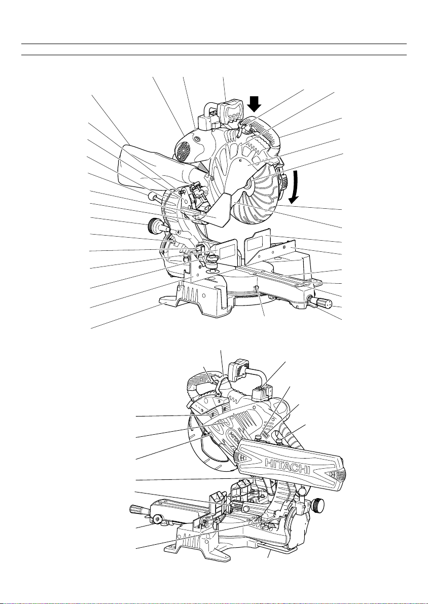
NAME OF PARTS
Dust bag
Motor
Nameplate
Digital display
(only C12LSH)
Motor head
Lever (A)
Gear case
Locking pin
Hinge
Holder (A)
Clamp lever
Sub cover
Laser marker
Knob (B)
Indicator
(For right bevel
scale)
Set pin (A)
Sub fence (B)
Vise assembly
Fence (B)
Base
5 mm machine screw
Belt cover
Trigger switch
Fig. 1
Lever (A)
Indicator
(For miter scale)
Switch (For laser
marker) (Only C12LSH)
Handle
Spindle cover
Washer (B)
Rotation
direction
Lower guard
Saw blade
Sub fence (A)
Fence (A)
Table insert
5 mm machine
screw
Tur ntable
Side handle
Lever
Slide securing knob (A)
Switch (For laser
marker)(Only C12RSH)
Slide Securing Knob (B)
Spindle lock
Adjuster (For laser marker)
Knob (A)
Indicator (For left bevel scale)
4
Guard
Holder
Fig. 2
Page 5

SPECIFICATIONS
Item Model C 12LSH / C 12RSH
Motor Type Series commutator motor
Laser Marker Maximum output Po<3mW CLASS II Laser Product
Digital Display (Only Model C12LSH) Precision ±0.5°
Applicable Outside Dia. 305 mm
saw blade Hole Dia. 25.4 mm
No load speed 4000/min (For New Zealand : 3800/min)
Max. Head Turntable Max. sawing dimension
sawing Miter 0 0 Max. Height 107 mm
dimension
Miter sawing range Left 0° – 46° Right 0° – 57°
Bevel sawing range Left 0° – 45° Right 0° – 45°
Compound sawing range Left (Bevel) 0° – 45°, Left (Miter) 0° – 45°, Right (Miter) 0° – 31°
Net weight C12LSH 30 kg C12RSH 29 kg
Cord 2 Conductor type cable 1.8 m
Power source Single-phase AC 50Hz
Voltage (Volts) (230V, 240V)
Power input 1520 W (For New Zealand : 1600 W)
(lambda) 654 nm
Laser medium Laser Diode
Max. Width 312 mm
or
* Max. Height 120 mm
Max. Width 260 mm
0 Left 45° Max. Height 107 mm
0 Right 57° Max. Height 107 mm
Bevel Left 45° 0 Max. Height 70 mm
Rigth 45° 0 Max. Height 45 mm
Compound Left 45° Left 45° Max. Height 70 mm
Left 45° Right 31° Max. Height 70 mm
Right 45° Right 45° Max. Height 45 mm
Right 45° Left 31° Max. Height 45 mm
Right (Bevel) 0° – 45°, Right (Miter) 0° – 45°, Left (Miter) 0° – 31°
or Max. Width 220 mm
Right 45° or
With aux. board 25 mm
* Max. Height 120 mm
Max. Width 180 mm
With aux. board 25 mm
Max. Width 170 mm
or
* Max. Height 120 mm
Max. Width 130 mm
With aux. board 25 mm
Max. Width 312 mm
or
* Max. Height 75 mm
Max. Width 260 mm
With aux. board 25 mm
Max. Width 312 mm
or
* Max. Height 50 mm
Max. Width 260 mm
With aux. board 25 mm
Max. Width 220 mm
or
* Max. Height 75 mm
Max. Width 180 mm
With aux. board 25 mm
Max. Width 265 mm
or
* Max. Height 75 mm
Max. Width 220 mm
With aux. board 25 mm
Max. Width 220 mm
or
* Max. Height 50 mm
Max. Width 180 mm
With aux. board 25 mm
Max. Width 265 mm
or
* Max. Height 50 mm
Max. Width 220 mm
With aux. board 25 mm
5
Page 6
When cutting the workpiece which has the dimension of
“*” there might be some possibility of the lower end of
the circular saw to touch with the workpiece, even if the
motor head is located at the lower limit position. Pay
attention when cutting the workpiece. For further details,
refer to “PRACTICAL APPLICATIONS” on page 13. Mount
the auxiliary board on the fence surface (Refer ( ) the
thickness of auxiliary board). Refer to "5. Cutting large
workpieces" on page 14 (Fig. 31).
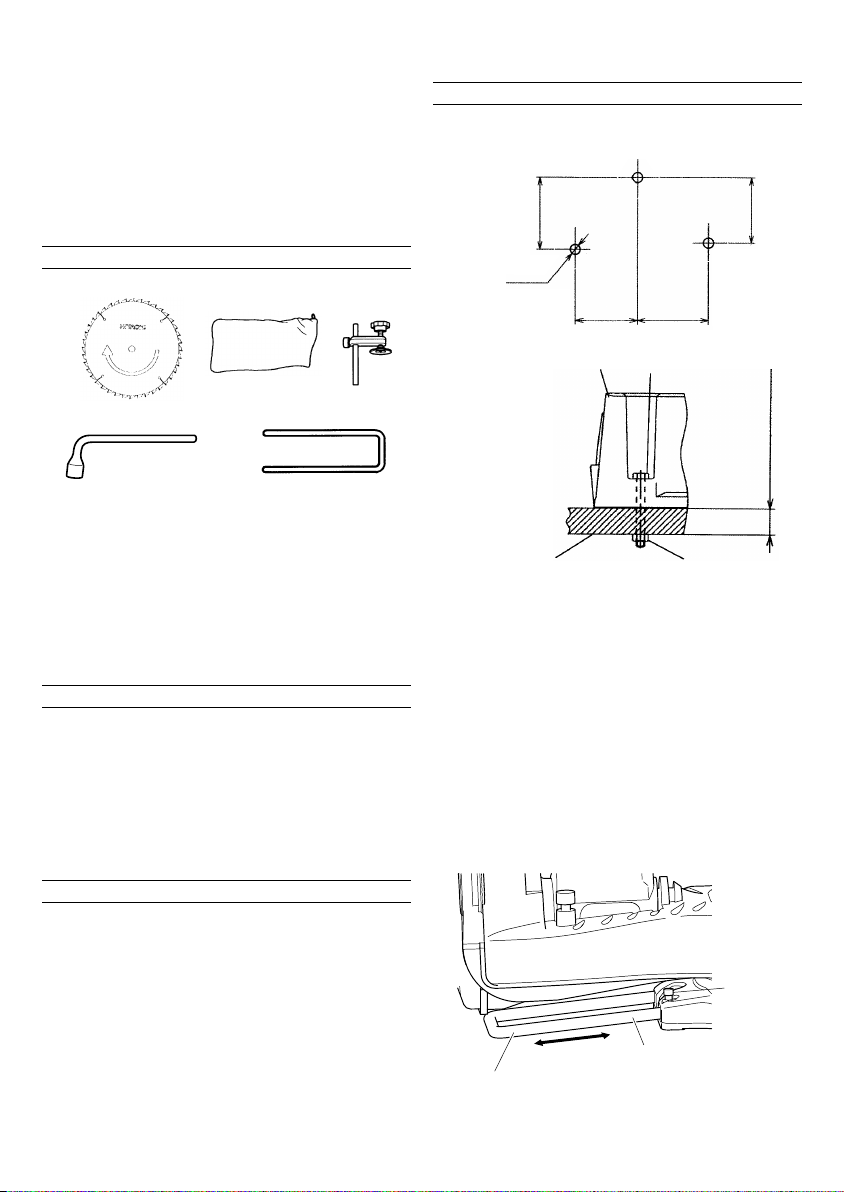
STANDARD ACCESSORIES
12 3
PREPARATION BEFORE OPERATION
Make the following preparations before operating the
power tool:
1. Installation
256 mm
9 mm
3 holes
281 mm
45
Fig. 3
1 305 mm TCT Saw blade (1 piece) (For wood)
2 Dust bag (1 piece)
For how to use, refer to page 19.
3 Vise Assembly w/knob bolt (1 piece)
For how to use, refer to page 13.
4 17 mm BOX wrench (1 piece)
5 Holder (1 piece)
For how to use, refer this page.
6 Washer (C) (Only For Australia)
OPTIONAL ACCESSORIES...sold separately
1 Extension Holder and Stopper
2 Crown molding Vise Ass’y
(Include Crown molding Stopper (L))
3 Crown molding Stopper (L)
4 Crown molding Stopper (R)
NOTE
Accessories are subject to change without any
obligation on the part of the HITACHI.
APPLICATIONS
Wood and aluminum sash.
244 mm
Work bench 8 mm nut
Attach the power tool to a level, horizontal work bench
in accordance with Fig. 4.
Select 8 mm diameter bolts suitable in length for the
thickness of the work bench.
Bolt length should be at least 40 mm plus the thickness
of the work bench.
For example, use 65 mm or larger bolts for a 25 mm
thick work bench.
The holder attached to the rear of the base helps
stabilize the power tool.
Holder adjustment:
Loosen the 6 mm bolt with the 10 mm box wrench.
Adjust the holder until its bottom surface contacts the
work bench surface.
After adjustment, firmly tighten the 6 mm bolt.
Fig. 4
281 mm
8mm boltBase
25 mm thick bench
6 mm Bolt
Move
Adjust the holder until its bottom surface contacts
the work bench surface.
6
Holder
Fig. 5
Page 7

2. Releasing the locking pin
When the power tool is prepared for shipping, its main
parts are secured by a locking pin.
Move the handle slightly so that the locking pin can
be disengaged.
Handle
(2) Next, check that the lower guard returns to the original
position when the handle is raised.
Lever (A)
Handle
Locking pin
Pull
Fig. 6
NOTE
Lowering the handle slightly will enable you to
disengage the locking pin more easily and safely.
The lock position of the locking pin is for carrying and
storage only.
3. Installing the dust bag, holder, stopper and vises
(The holder and stopper are optional accessories.)
Attach the dust bag and vise assembly as indicated
in Fig. 1 and Fig. 2.
BEFORE USING
1. Make sure the power source is appropriate for the
tool.
WARNING
Never connect the power tool unless the available AC
power source is of the same voltage as that specified
on the nameplate of the tool.
Never connect this power tool to a DC power source.
2. Make sure the trigger switch is turned OFF.
WARNING
If the power cord is connected to the power source
with the trigger switch turned ON the power tool will
start suddenly and can cause a serious accident.
3. Check the saw blade for visible defects.
Confirm that the saw blade is free of cracks or other
visible damage.
4. Confirm that the saw blade is attached securely to
the power tool.
Using the supplied 17 mm box wrench, tighten the
10 mm bolt on the saw blade spindle to secure the
saw blade.
For details, see Fig. 55-a, Fig. 55-b, Fig. 55-c and Fig.
55-d in the section on “SAW BLADE MOUNTING AND
DISMOUNTING”.
5. Check to see that the lower guard operates smoothly
CAUTION
This slide compound miter saw is equipped with a
saw head lock as safety device.
To lower the saw head to cut, the lock must be released
by pressing the lever (A) with your thumb.
(1) When you push down the handle while pushing the
lever (A), check that the lower guard revolves
smoothly (Fig. 7).
Lower guard
Fig. 7
6. Confirm the position of the spindle lock before using
the tool.
After installing the saw blade, confirm that the spindle
lock has been returned to the retract position before
using the power tool (see Fig. 2).
7. Check the lower limit position of the Saw Blade.
Although it was adjusted before shipment, carefully
check the height of the saw blade. Confirm that the
saw blade can be lowered 9 mm to 11 mm below the
table insert. For details, see the section on “Checking
the saw blade lower limit position”.
8. Check the Power Receptacle.
To prevent overheating, accidental stopping or
intermittent operation, confirm that the power cord
plug fits properly in the electrical receptacle and does
not fall out after it is inserted. Repair or replace the
receptacle if it is faulty.
9. Confirm the tool’s power cord is not damaged.
Repair or replace the power cord if an inspection
indicates that it is damaged
AFTER CONNECTING THE POWER PLUG TO AN APPROPRIATE AC POWER SOURCE, CHECK THE OPERATION OF THE TOOL AS FOLLOWS:
10. Trial Run
After confirming that no one is standing behind, the
power tool start and confirm that no operating
abnormalities exist before attempting a cutting
operation.
11. Inspect the rotating stability of the saw blade.
For precise cutting, rotate the saw blade and check
for deflection to confirm that the blade is not
noticeably unstable; otherwise vibrations might occur
and cause an accident.
7
Page 8

BEFORE CUTTING
1. Cutting a groove on the guard
Holder (A) has a guard (see Fig. 8) into which a groove
must be cut.
Loosen the 6 mm knob bolt to retract the guard
slightly. After placing a suitable wooden piece to sit
on the fence and the table surfaces, fix it with the vise
assembly.
After the switch has been turned on and the saw blade
has reached maximum speed, slowly lower the handle
to cut a groove on the guard.
Handle
Saw blade
Vise assembly
Fence (B)
Workpiece
Fig. 8
CAUTION
Do not cut the groove too quickly; otherwise the guard
might become damaged.
2. Positioning the table insert
5 mm machine
screw
Workpiece
Holder (A)
6 mm knob bolt
Guard
Fence (A)
Saw blade
Table insert
Table inserts are installed on the turntable. When
shipping the tool from the factory, the table inserts
are so fixed that the saw blade does not contact them.
The burr of the bottom surface of the workpiece is
remarkably reduced, if the table insert is fixed so that
the gap between the side surface of the table insert
and the saw blade will be minimum. Before using the
tool, eliminate this gap in accordance with the
following procedure.
(1) Right angle cutting
Loosen the three 5 mm machine screws, then secure
the left side table insert and temporarily tighten the 5
mm machine screws of both ends. Then fix a
workpiece (about 200 mm wide) with the vise
assembly and cut it off. After aligning the cutting
surface with the edge of the table insert, securely
tighten the 5 mm machine screws of both ends.
Remove the workpiece and securely tighten the 5 mm
center machine screw. Adjust the right hand table
insert in the same way.
(2) Left and right bevel angle cutting
Adjust the table insert in the manner shown in Fig. 9-
b and Fig. 9-c following the same procedure for right
angle cutting.
CAUTION
After adjusting the table insert for right angle cutting,
the table insert will be cut to some extent if it is used
for bevel angle cutting.
When bevel cutting operation is required, adjust the
table insert for bevel angle cutting.
3. Checking the saw blade lower limit position
8 mm depth
adjustment
bolt
Hinge
Gear case
Saw blade
5 mm machine
screw
Table insert
8
[Right angle cutting]
Fig. 9-a
Workpiece
[Left bevel angle cutting]
Fig. 9-b
Saw blade
[Right bevel angle cutting]
Workpiece
Fig. 9-c
Saw blade
Table insert
5 mm machine
screw
Turntable
Fig. 10-a
Tur n
8 mm depth
adjustment
bolt
Hinge
Fig. 10-b
Check that the saw blade can be lowered 9 mm to 11
mm below the table insert as shown in Fig. 10-a.
When you replace a saw blade with a new one, adjust
the lower limit position so that the saw blade will not
cut the turntable or complete cutting cannot be done.
To adjust the lower limit position of the saw blade,
follow the procedure (1) indicated below. (Fig. 10-b)
Furthermore, when changing the position of a 8 mm
depth adjustment bolt that serves as a lower limit
position stopper of the saw blade.
Gear case
Page 9
(1) Turn the 8 mm depth adjustment bolt, change the
height where the bolt head and the hinge contacts,
and adjust the lower limit position of the saw blade.
NOTE
Confirm that the saw blade is adjusted so that it will
not cut into the turntable.
4. Lower limit position of saw blade when cutting a large
workpiece
NOTE
When cutting a workpiece exceeding 107 mm in height
in right-angle cutting or 70 mm in left bevel angle
cutting or 45 mm in right bevel angle cutting, adjust
the lower limit position so that the base of the motor
head (see Fig. 10-a) will not come in contact with the
workpiece.
To adjust the lower limit position of the saw blade, follow
the procedure (1) shown in Fig. 10-a.
(1) Lower the motor head, and turn the 8 mm depth
adjustment bolt and make adjustments so that there
can be a clearance of 2 mm to 3 mm between the
lower limit position of the motor head and the top of
the workpiece at the saw blade's lower limit position
where the head of the 8 mm depth adjustment bolt
contacts the hinge.
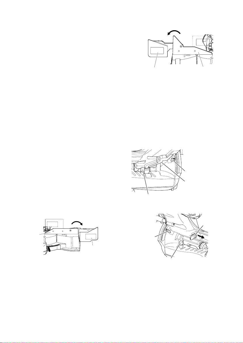
5. Confirmation for use of sub fence (A)
WARNING
In the case of right bevel cutting, turn the sub fence
(A) clockwise. Unless it is turned clockwise, the main
body or saw blade may contact the sub fence (A),
resulting in an injury.
This power tool is equipped with a sub fence (A).
In the case of direct angle cutting and left bevel angle
cutting, use the sub fence (A). Then, you can realize
stable cutting of the material with a wide back face.
In the case of right bevel cutting, raise the sub fence
(A) up as illustrated in Fig. 11 and then turn it
clockwise.
Left bevel angle cutting
Direct angle cutting
Fence (A)
6. Confirmation for use of sub fence (B)
WARNING
In the case of left bevel cutting, turn the sub fence (B)
counterclockwise. Unless it is turned
counterclockwise, the main body or saw blade may
contact the sub fence (B), resulting in an injury.
This power tool is equipped with a sub fence (B). In
the case of direct angle cutting and right bevel angle
cutting, use the sub fence (B). Then, you can realize
stable cutting of the material with a wide back face. In
the case of left bevel cutting, raise the sub fence (B)
up as illustrated in Fig.12 and turn it counterclockwise.
Tur n
Fig. 11
Right bevel angle
cutting
Sub fence (A)
Right bevel angle cutting
Left bevel angle
cutting
Sub fence (B)
7. Oblique angle
Before the power tool is shipped from the factory, it
is adjusted for 0°, right angle, left 45° bevel cutting
angle and right 45° bevel cutting angle with the 8 mm
set screw, 8 mm bolt (A) and 8 mm bolt (B).
When changing the adjustment, change the height of
the 8 mm set screw, 8 mm bolt (A), or 8 mm bolt (B)
by turning them.
When changing the bevel angle to the right 45°, pull
the set pin (A) on the direction shown in Fig. 13-b and
incline the motor head to the right.
When adjusting the motor head to 0°, always return
the set pin (A) to its initial position as shown in Fig.
13-b.
8 mm bolt (B)
(Stopper for right 45° bevel angle)
Indicator
(For right
bevel scale)
8. Securing the workpiece
WARNING
Always clamp or vise to secure the workpiece to the
fence; otherwise the workpiece might be thrust from
the table and cause bodily harm.
Tur n
Direct angle cutting
Fence (B)
Fig. 12
Indicator
(For left bevel scale)
8 mm set screw
(Stopper for 0° not
shown)
Fig. 13-a
Set pin (A)
Pull
8 mm bolt (A)
(Stopper for left 45° bevel angle)
Fig. 13-b
9
Page 10
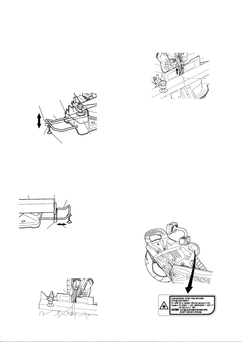
9. Installing the holders ... (Optional accessory)
The holders help keep longer workpieces stable and
in place during the cutting operation.
(1) As indicated in Fig. 14, use a steel square for aligning
the upper edge of the holders with the base surface.
Loosen the 6 mm wing nut. Turn a height adjustment
bolt 6 mm, and adjust the height of the holder.
(2) After adjustment, firmly tighten the 6 mm wing nut
and fasten the holder with the 6 mm knob bolt
(optional accessory). If the length of Height
Adjustment Bolt 6 mm is insufficient, spread a thin
plate beneath. Make sure the end of Height
Adjustment Bolt 6 mm does not protrude from the
holder.
6 mm knob bolt
(Optional accessory)
Steel square
6 mm wing nut
(Optional accessory)
10. Stopper for precision cutting ... (Stopper and holder
are optional accessory)
The stopper facilitates continuous precision cutting
in lengths of 285 mm to 450 mm.
To install the stopper, attach it to the holder with the 6
mm knob bolt as shown in Fig. 15.
Workpiece
Holder
(Optional
accessory)
Base surface
Height adjustment bolt 6 mm
(Optional accessory)
Fig. 14
Stopper (Optional accessory)
Holder (Optional accessory)
(2) Miter cutting and compound cutting
(Miter cutting + bevel cutting)
Upon lowering the motor section, the lower guard is
raised and the saw blade appears.
Align the ink line with the saw blade (Fig. 17).
Move the
guard
backward
Sub fence (B)
Fig. 17
CAUTION
In some arrangements when the turntable is rotated,
the guard projects from the fence surface. Loosen the
6 mm knob bolt and push the guard to the retracted
position. Never lift the lower guard while the saw
blade is rotating. When cutting at an angle to the right
or more, please slide the guard to the rear. The guard
and sub-fence (A) and sub-fence (B) will not only make
contact and adversely affect cutting accuracy, this
could also result in damage to the guard.
12. Position adjustment of laser line
WARNING
* Make sure before plugging the power plug into the
receptacle that the main body and the laser marker
are turned off.
* Exercise utmost caution in handling a switch trigger
for the position adjustment of the laser line, as the
power plug is plugged into the receptacle during
operation.
If the switch trigger is pulled inadvertently, the saw
blade can rotate and result in unexpected accidents.
* Do not remove the laser marker to be used for other
purposes.
CAUTION
Lower guard
6 mm knob
Marking
(pre-marked)
bolt
6 mm knob bolt
(Optional accessory)
11. Using an ink line
(1) Right angle cutting
Loosen the 6 mm knob bolt and contact the tip of the
guard with the workpiece.
Aligning the ink line on the workpiece with the groove
of the guard, the workpiece is cut on the ink line (Fig.
16).
Saw blade groove
Marking (pre-marked)
10
Move
Fig. 15
Fig. 16
Guard
6 mm knob
bolt
Workpiece
Fig. 18
Page 11

Fig. 19
* Laser radiation- Do not stare into beam.
* Laser radiation on work table. Do not stare into beam.
If your eye is exposed directly to the laser beam, it
can be hurt.
* Do not dismantle it.
* Do not give strong impact to the laser marker (main
body of tool); otherwise, the position of a laser line
can go out of order, resulting in the damage of the
laser marker as well as a shortened service life.
* Keep the laser marker lit only during a cutting
operation. Prolonged lighting of the laser marker can
result in a shortened service life.
* Use of controls or adjustments or performance of
procedures other than those specified herein may
result in hazardous radiation exposure.
NOTE
* Perform cutting by overlapping the ink line with the
laser line.
* When the ink line and the laser line are overlapped,
the strength and weakness of light will change,
resulting in a stable cutting operation because you
can easily discern the conformity of lines. This ensures
the minimum cutting errors.
* In outdoor or near-the-window operations, it may
become difficult to observe the laser line due to the
sunlight. Under such circumstances, move to a place
that is not directly under the sunlight and engage in
the operation.
* Do not tug on the cord behind the motor head or hook
your finger, wood and the like around it; otherwise,
the cord may come off and the laser marker may not
be lit up.
Ink lining can be easily made on this tool to the laser
marker. A switch lights up the laser marker. (Fig. 20)
Depending upon your cutting choice, the laser line
can be aligned with the left side of the cutting width
(saw blade) or the ink line on the right side.
The laser line is adjusted to the width of the saw blade
at the time of factory shipment. Adjust the positions
of the saw blade and the laser line taking the following
steps to suit the use of your choice.
Switch
(1) Light up the laser marker and make a groove of about
5 mm deep on the workpiece that is about 20 mm in
height and 150 mm in width. Hold the grooved
workpiece by vise as it is and do not move it. For
grooving work, refer to “13.Groove cutting
procedures” on page 19.
Fig. 21
Groove
Fig. 22
Saw blade
Cutting width
Tur n
Adjuster
Workpiece
Marking
(pre-marked)
(2) Then, turn the adjuster and shift the laser line. (If you
turn the adjuster clockwise, the laser line will shift to
the right and if you turn it counterclockwise, the laser
line will shift to the left.) When you work with the ink
line aligned with the left side of the saw blade, align
the laser line with the left end of the groove. (Fig. 22)
When you align it with the right side of the saw blade,
align the laser line with the right side of the groove.
Vise assembly
Move
Laser line
(3) After adjusting the position of the laser line, draw a
right-angle ink line on the workpiece and align the
ink line with the laser line. When aligning the ink line,
slide the workpiece little by little and secure it by vise
at a position where the laser line overlaps with the
ink line. Work on the grooving again and check the
position of the laser line. If you wish to change the
laser line's position, make adjustments again
following the steps from (1) to (3).
Fig. 20
Laser line
Marking
(pre-marked)
Fig. 23
Laser line
11
Page 12

NOTE
Check and make sure on a periodic basis if the position
of the laser line is in order. As regards the checking
method, draw a right-angle ink line on the workpiece
with the height of about 20 mm and the width of 150
mm, and check that the laser line is in line with the
ink line [The deviation between the ink line and the
laser line should be less than the ink line width (0.5
mm)]. (Fig. 23)
13. DIGITAL DISPLAY PANEL (for C12LSH)
Miter angle window
(Displays arrows show angle and
direction that turntable is rotating.
Left is ← Right is →.)
Bevel angle window
(Displays arrows showing motor
head bevel angle and bevel
direction. Left is ← Right is →.)
Miter angle reset button
Digital display switch
(for C12LSH)
(Also serves as laser marker
power switch.)
(1) Tu rning on the digital display switch shows 0° for both
miter and bevel angle, regardless of main unit angle.
(2) Align the main unit angle with the tilt angle (0°) and
miter angle (0°) and hold down their reset buttons for
at least 0.2 second.
(3) Turning on the laser marker switch while the digital
display switch is on, lights up the laser marker. (On
the C12RSH, only the laser marker switch.)
CAUTION
When operating the digital panel, have the motor head
section at the top limit position and the blade stopped.
NOTE
• Before starting to cut, align the main unit to the miter
angle 0° and the bevel angle 0° and hold down the
reset buttons for at least 0.2 second. If you press the
digital display switch to ON without aligning the main
unit to 0°, then the figures appearing on the digital
display and the main unit angle will not match.
• The laser marker will not light up if the digital display
switch is turned off. (only on C12LSH)
• Do not use the main unit near equipment that
generates electrical noise such as generators.
Electrical noise might cause faulty readings or
operation on the digital display.
12
Laser marker switch
Fig. 25-a
Bevel angle reset button
Back light ON/OFF switch (Press and the
switch illuminates. Press again and the
Fig. 24
CAUTION
If the figure shown on the miter angle digital display
is different from the positive stop angle (for example,
45.0° → 45.5°, 31.6° → 32.0°) then the positive stop
has probably deviated slightly from its correct
position. If this happens, do as follows.
(1) Move the turntable left and right with the side handle
loosened, and set the turntable to the correct position.
(2) If the figures on the display and positive stop still do
not match, then return the turntable to the 0° position.
Next move the turntable left and right with the side
handle loosened as shown in Fig. 25-b. After setting
it to the correct position 0°, press the reset button
again as shown in Fig. 24.
lighting turns off.)
Side handle
Tur ntable
Move the turntable left and right with the side
handle loosened and set it to the correct position.
Fig. 25-b
Page 13

PRACTICAL APPLICATIONS
WARNING
*To avoid personal injury, never remove or place a
workpiece on the table while the tool is being
operated.
* Never place your limbs inside of the line next to
warning sign while the tool is being operated. This
may cause hazardous conditions (see Fig. 26).
Warning signLine Warning sign Line
Fig. 26
1. Switch operation
Pull the trigger to turn on the switch, release it to shut
it off.
After releasing the trigger, make sure the trigger has
gone all the way back and the switch is turned off.
Trigger switch
Fig. 27
2. Using the Vise Assembly (Standard accessory)
(1) The vise assembly can be mounted on either the left
fence {Fence (B)} or the right fence {Fence (A)} by
loosening the 6mm wing bolt (A).
(2) The screw holder can be raised or lowered according
to the height of the workpiece by loosening the 6mm
wing bolt (B). After the adjustment, firmly tighten the
6mm wing bolt (B) and fix the screw holder.
(3) Turn the upper knob and securely fix the workpiece
in position (Fig. 28).
6mm wing
bolt (B)
Fence
Vise shaft
6mm wing bolt (A)
Screw holder
Fig. 28
Knob
Vise plate
Workpiece
WARNING
Always firmly clamp or vise to secure the workpiece
to the fence; otherwise the workpiece might be thrust
from the table and cause bodily harm.
CAUTION
Always confirm that the motor head (see Fig. 1) does
not contact the vise assembly when it is lowered for
cutting. If there is any danger that it may do so, loosen
the 6 mm wing bolt (B) and move the vise assembly
to a position where it will not contact the saw blade.
3. Cutting Operation
(1) As shown in Fig. 29 the width of the saw blade is the
width of the cut. Therefore, slide the workpiece to the
right (viewed from the operator’s position) when
length b is desired, or to the left when length a is
desired.
If a laser marker is used, align the laser line with the
left side of the saw blade, and then align the ink line
with the laser line.
(2) Once the saw blade reaches maximum speed, push
the handle down carefully until the saw blade
approaches the workpiece.
(3) Once the saw blade contacts the workpiece, push the
handle down gradually to cut into the workpiece.
(4) After cutting the workpiece to the desired depth, turn
the power tool OFF and let the saw blade stop
completely before raising the handle from the
workpiece to return it to the full retract position.
Adjusting line
ab
a
b
Marking
(pre-marked)
CAUTION
* Increased pressure on the handle will not increase the
cutting speed.
On the contrary, too much pressure may result in
overload of the motor and/or decreased cutting
efficiency.
WARNING
* Confirm that the trigger switch is turned OFF and the
power plug has been removed from the receptacle
whenever the tool is not in use.
* Always turn the power off and let the saw blade stop
completely before raising the handle from the
workpiece.
If the handle is raised while the saw blade is still
rotating, the cut-off piece may become jammed
against the saw blade causing fragments to scatter
about dangerously.
* Every time one cutting or deep-cutting operation is
finished, turn the trigger switch off, and check that
the saw blade has stopped. Then raise the handle,
and return it to the full retract position.
* Be absolutely sure to remove the cut material from
the top of the turntable, and then proceed to the next
step.
a
(Front view)
Marking
b
(pre-marked)
Fig. 29
13
Page 14

* Continued cutting operation can result in overload of
the motor. Touch the motor and if it's hot, stop your
cutting operation once and rest for 10 minutes or so,
and then restart your cutting operation.
* Do not operate the head section or lift up the main
unit while grasping the digital display (Fig. 1) as this
could cause damage to the digital display.
4. Cutting narrow workpieces (Press cutting)
Slide the hinge down to holder (A), then tighten the
slide securing knob (A)/(B) (see Fig. 2) as indicated in
Fig. 30.
Lower the handle to cut the workpiece.
Using the power tool this way will permit cutting of
workpieces of up to 107 mm square.
Hinge
Holder (A)
Fig. 30
5. Cutting large workpieces
There may be case when a complete cutting cannot
be done depending on the height of workpiece. In this
case, mount an auxiliary board with the 6 mm flat
head screws and the 6 mm nuts using the 7 mm holes
on the fence surface (two holes on each side). (Fig.
31)
Refer to page 5 “SPECIFICATIONS” for the thickness
of the auxiliry board.
Auxiliary board
6 mm nut
Fence
Fig. 31
6. Cutting wide workpieces (Slide cutting)
(1) Workpieces up to 107 mm high and 312 mm wide:
Loosen the slide securing knob (A) (see Fig. 2), grip
the handle and slide the saw blade forward.
Then press down on the handle and slide the saw
blade back to cut the workpiece as indicated in Fig.
32. This facilitates cutting of workpieces of up to 107
mm in height and 312 mm in width.
(2) Workpieces up to 120 mm high and 260 mm wide:
Workpieces of up to 120 mm in height and up to 260
mm in width can be cut in the same manner as
described in paragraph 6-(1) above.
14
Handle
Press down
Workpiece
6 mm flad hd.
screw
1 Pull forward
3 Push rearward
to cut
Workpiece
Fig. 32
CAUTION
* When cutting a workpiece of 120 mm height, adjust
the lower limit position of the motor head so that the
gap between the lower edge of the motor head and
the workpiece will be 2 to 3 mm at the lower limit
position.
* If the handle is pressed down with excessive or lateral
force, the saw blade may vibrate during the cutting
operation and cause unwanted cutting marks on the
workpiece, thus reducing the quality of the cut.
Accordingly, press the handle down gently and
carefully.
* In slide cutting, gently push the handle back
(rearwards) in a single, smooth operation.
Stopping the handle movement during the cut will
cause unwanted cutting marks on the workpiece.
WARNING
* For slide cutting, follow the procedures indicated
above in Fig. 32.
Forward slide cutting (toward the operator) is very
dangerous because the saw blade could kick upward
from the workpiece. Therefore, always slide the
handle away from the operator.
* Always return the carriage to the full rear position after
each crosscut operation in order to reduce the risk of
injury.
* Never put your hand on the side handle during the
cutting operation because the saw blade comes close
to the side handle when the motor head is lowered.
7. Bevel cutting procedures
(1) Loosen the clamp lever and bevel the saw blade to
the left or to the right.
When tilting the motor head to the right pull the set
pin (A) towards the rear.
The clamp lever adopts a latchet system. When
contacting the work bench and the main body, pull
the clamp lever in the direction of the arrow mark as
illustrated in Fig. 33, and change the direction of the
clamp lever.
(2) Adjust the bevel angle to the desired setting while
watching the bevel angle scale and indicator, then
secure the clamp lever.
(3) Follow the procedures indicated in paragraphs 4,5 and
6 above. For maximum dimensions for bevel cutting,
refer to “SPECIFICATIONS” table on page 5.
Handle
2
Press down
Page 15

Clamp Lever
Holder (A)
Pull
Clamp lever
Loosen
Tighten
Knob (B)
(for right bevel scale)
WARNING
CAUTION
8. Bevel angle fine adjustment
Indicator
When the workpiece is secured on the left or right
side of the blade, the short cut-off portion will come
to rest on the right or left side of the saw blade. Always
turn the power off and let the saw blade stop
completely before raising the handle from the
workpiece.
If the handle is raised while the saw blade is still
rotating, the cut-off piece may become jammed
against the saw blade causing fragments to scatter
about dangerously.
When stopping the bevel cutting operation halfway,
start cutting after pulling back the motor head to the
initial position.
Starting from halfway, without pulling back, causes
the lower guard to be caught in the cutting groove of
the workpiece and to contact the saw blade.
When cutting a workpiece of 75 mm height in the left
45° bevel cutting position or a workpiece of 50 mm
height in the right 45° bevel cutting position, adjust
the lower limit position of the motor head so that the
gap between the lower edge of the motor head and
the workpiece will be 2 to 3 mm at the lower limit
position (refer to “3. Checking the saw blade lower
limit position” on page 8).
Handle
Bevel scale
Fig. 33
Set pin (A)
Fig. 35
(1) Grip the handle on the motor head and position it at
the bevel angle you need. Temporarily tighten the
clamp lever.
CAUTION
If not tightened firmly enough the motor head might
suddenly move or slip, causing injuries. Be sure to
tighten the motor head section enough so it will not
move.
(2) When making fine adjustments of the bevel angle, turn
the knob (B) while supporting the handle with your
hand.
NOTE
Turning knob (B) clockwise, allows fine adjustment of
the main unit to the left (as seen from front).
Tur ning knob (B) counterclockwise, allows fine
adjustment of the main unit to the right (as seen from
front).
(3) After adjusting to the desired angle, tighten the clamp
lever and clamp the motor head.
CAUTION
Always check that the clamp lever is secured and the
motor head is clamped. If you attempt angle cutting
without clamping the motor head, then the motor
head might shift unexpectedly causing injuries.
9. Miter cutting procedures
(1) Loosen the side handle and pull up the lever for angle
stoppers. Then, adjust the turntable until the indicator
aligns with desired setting on the miter scale (Fig. 36).
Indicator
(For miter scale)
Side handle
8 mm bolt (B)
Fig. 34
Clamp lever
Knob (B)
Turntable
Miter scale
Tur n the
turntable
Fig. 36
Lever
Pull up
Tighten
Loosen
15
Page 16

(2) Re-tighten the side handle to secure the turntable in
the desired position.
(3) The miter scale (Fig. 37) indicates both the cutting angle
on the angle scale and the gradient on the grade scale.
(4) The gradient, which is the ratio of the height to the
base of the triangular section to be removed, may be
used for setting the miter scale instead of the cutting
angle, if desired (see Fig. 37).
(5) Therefore, to cut a workpiece at a grade of 2/10, set
the indicator to position a as indicated in Fig. 37.
Angle scale
Grade scale
Fig. 37
Fig. 38
NOTE
* Positive stops are provided at the right and left of the
0° center setting, at 15°, 22.5°, 31.6° and 45° settings.
Check that the miter scale and the tip of the indicator
are properly aligned.
* Operation of the saw with the miter scale and indicator
out of alignment, or with the side handle not properly
tightened, will result in poor cutting precision.
10. Miter angle fine adjustment
(1) Rotate the turntable to the miter angle you need.
(2) When making fine adjustments of the miter angle, turn
the knob (A) while pulling up the lever (Fig. 39).
Turntable
Fig. 39
NOTE
Turning knob (A) clockwise, allows fine adjustment
of the turntable to the right. Turning knob (A)
counterclockwise, allows fine adjustment of the
turntable to the left.
(3) After adjusting to the desired angle, tighten the side
handle.
CAUTION
Always check that the side handle is secured and the
turntable is clamped.
If you attempt angle cutting without clamping the
turntable, then the turntable might shift unexpectedly
causing injuries.
16
a
Miter scale
Knob (A)
Side handle
11. Compound cutting procedures
Compound cutting can be performed by following the
instructions in 7 and 10 above. For maximum
dimensions for compound cutting, refer to
“SPECIFICATIONS” table on page 5.
CAUTION
Always secure the workpiece with the right or left hand
and cut it by sliding the round portion of the saw
backwards with the left hand.
It is very dangerous to rotate the turntable to the left
during compound cutting because the saw blade may
come into contact with the hand that is securing the
workpiece.
In case of compound cutting (angle + bevel) by left
bevel, turn the sub-fence (B) counterclockwise, and
engage in the cutting operation.
In case of compound cutting (angle + bevel) by right
bevel, turn the sub-fence (A) clockwise, and engage
in the cutting operation.
12. Crown molding cutting procedures
Fig. 40 shows two common crown molding types
having angles of (q) 38° and 45°.
For the typical crown molding fittings, see Fig. 41.
A Upper surface ceiling
B Lower surface
Wall
Fig. 40
Ceiling
Wall
1
Inside corner Outside corner
Fig. 41
The table below shows the miter angle and the bevel
angle settings that are ideal for the two crown molding
types.
NOTE
For convenience, positive stops are provided for the
miter setting (left and right 31.6°) positions.
For miter cut setting
If the turntable has been set to either of the angles
described, move the turntable adjusting side handle
a little to the right and left to stabilize the position
and to properly align the miter angle scale and the tip
of the indicator before the operation starts.
For bevel cut setting
Turn the clamp lever on bevel section to the left and
check that the position is stable and that the bevel
angle scale and the tip of the indicator are properly
aligned. Then tighten the clamp lever.
2
34
Page 17

To process crown To process crown
Type of
Crown
Molding
45° Type right 35.3° left 30° left 35.3° left 30°
38° Type right 31.6° left 33.9° left 31.6° left 33.9°
(1) Setting to cut crown moldings at positions 1 and 4
(2) Setting to cut crown moldings at positions 2and 3
molding at positions molding at positions
1 and 4 in Fig. 41. 2 and 3 in Fig. 41.
Miter Angle Bevel Angle Miter Angle Bevel Angle
Setting Setting Setting Setting
( mark) ( mark) ( mark) ( mark)
( mark) ( mark) ( mark) ( mark)
in Fig. 41 (see Fig. 42; tilt the motor head to the left):
1 Tu rn the turntable to the right and set the Miter
Angle as follows:
* For 45° type crown moldings: 35.3° (
* For 38° type crown moldings: 31.6° ( mark)
2 Tilt the motor head to the left and set the Bevel
Angle as follows:
* For 45° type crown moldings: 30° (
* For 38° type crown moldings: 33.9° (
3 Position the crown molding so that the upper
surface (A in Fig. 40) contacts the fence as indicated
in Fig. 44.
in Fig. 41 (see Fig. 43; tilt the head to the left):
1 Tu rn the turntable to the left and set the Miter
Angle as follows:
* For 45° type crown moldings: 35.3° (
* For 38° type crown moldings: 31.6° (
2 Tilt the head to the left and set the Bevel Angle as
follows:
* For 45° type crown moldings: 30° ( mark)
* For 38° type crown moldings: 33.9° (
3 Position the crown molding so that the lower
surface (B in Fig. 40) contacts the fence as in
Fig. 45.
Head
1
Miter angle scale
Tur ntable
Bevel angle scale
4
Fig. 42
mark)
mark)
mark)
mark)
mark)
mark)
Fence (A)
Base
Head
Bevel angle scale
Fence (B)
(3) Setting to cut crown moldings at positions 1 and 4
in Fig. 41 (see Fig. 46; tilt the head to the right):
1 Turn the turntable to the right and set the Miter
Angle as follows:
* For 45° type crown moldings: 35.3° (
* For 38° type crown moldings: 31.6° ( mark)
2 Tilt the head to the right and set the Bevel Angle
as follows:
* For 45° type crown moldings: 30° (
* For 38° type crown moldings: 33.9° (
3 Position the crown molding so that the upper
surface (B in Fig. 40) contacts the fence as indicated
Fig. 48.
(4) Setting to cut crown moldings at positions 2 and 4
in Fig. 41 (see Fig. 47; tilt the head to the right):
1 Turn the turntable to the left and set the Miter
Angle as follows:
* For 45° type crown moldings: 35.3° (
* For 38° type crown moldings: 31.6° (
2 Tilt the head to the right and set the Bevel Angle
as follows:
* For 45° type crown moldings: 30° (
* For 38° type crown moldings: 33.9° ( mark)
3 Position the crown molding so that the lower
surface (A in Fig. 40) contacts the fence as in Fig.
49.
2
Tur ntable
Fig. 43
Fence
A
Table on base
Fig. 44
Fence
B
Table on base
Fig. 45
3
Miter angle scale
Base
B
A
mark)
mark)
mark)
mark)
mark)
mark)
17
Page 18

Fence
6mm knob bolt
Crown molding vise ass’y
(Optional accessories)
Knob
Crown molding
6mm
wing bolt
Crown molding stopper (L)
Crown molding stopper (R)
(Optional accessories)
Bevel angle scale
4
Miter angle scale
Turntable
Bevel angle scale
Fence (B)
3
Base
Head
Head
Fig. 46
Fig. 47
1
Fence (A)
Base
2
Miter angle scale
Turntable
• Crown molding Stopper (L)
• Crown molding Stopper (R)
Crown molding
Crown molding vise ass’y
(optional accessories)
6mm knob bolt
6mm wing bolt
(2) The crown molding vise (B) (Optional accessory)
can be mounted on either the left fence (Fence (B))
or the right fence (Fence (A)). It can unite with the
slope of the crown molding and vice can be
pressed down.
Then turn the upper knob, as necessary, to securely
attach the crown molding in position. To raise or lower
the vise assembly, first loosen the 6mm knob bolt.
After adjusting the height, firmly tighten the 6mm
wing bolt; then turn the upper knob, as necessary,
to securely attach the crown molding in position.
(See Fig. 50-b)
stopper (R)
(optional accessories)
6mm knob
bolt
Crown molding stopper (L)
(Optional accessories)
Fig. 50-a
Fence
B
Table on base
Fig. 48
Fence
A
Cutting method of crown molding without tilting the saw blade
(1) Crown molding Stopper (L) and (R) (optional
accessories) allow easier cuts of crown molding
without tilting the saw blade. Install them in the
base both-sides side to be shown in Fig. 50-a. After
inserting Tighten the 6mm knob bolts to secure
the crown molding Stoppers.
[Optional accessories used]
•Crown molding Vise Ass’y (Include Crown molding
Stopper (L))
18
Table on base
Fig. 49
A
B
Fig. 50-b
WARNING
Always firmly clamp or vise to secure the crown
molding to the fence; otherwise the crown molding
might be thrust from the table and cause bodily harm.
Do not bevel cutting. The main body or saw blade
may contact the sub fence, resulting in an injury.
CAUTION
Always confirm that the motor head (see Fig. 1) does
not contact the crown molding vise ass’y when it is
lowered for cutting. If there is any danger that it may
do so, loosen the 6mm knob bolt and move the crown
molding vise ass’y to a position where it will not
contact the saw blade.
Page 19

Position crown molding with its WALL CONTACT EDGE
against the guide fence and its CEILING CONTACT EDGE
against the crown molding Stoppers as shown in Fig. 50-b.
Adjust the crown molding Stoppers according to the size
of the crown molding.
Tighten the 6mm wing bolt to secure the crown molding
Stoppers.
Refer to the lower table for the miter angle.
Position Miter
in Fig. 41 angle
For inside
corner side of blade
For outside
corner side of blade
13. Groove cutting procedures
6 mm depth
adjustment
bolt
Stopper holder
Hinge
Grooves in the workpiece can be cut as indicated in
Fig. 51 by adjusting the 6 mm depth adjustment bolt.
Cutting depth adjustment procedure:
(1) Turn the stopper holder on the direction shown in Fig.
52.
Lower the motor head, and turn the 6 mm depth
adjustment bolt by hand. (Where the head of the 6
mm depth adjustment bolt contacts the hinge.)
(2) Adjust to the desired cutting depth by setting the
distance between the saw blade and the surface of
the turntable (see b in Fig. 51).
NOTE
When cutting a single groove at either end of the
workpiece, remove the unneeded portion with a
chisel.
1
Right 45°
2
3
4
Left 45°
Right 45°
Cut grooves with saw blade
Fig. 51
Tur n
Fig. 52
a
b
Tur ntable
Finished piece
Save the right
Save the left
side of blade
Save the right
Save the left
side of blade
Bottom line of
the groove
b
14. Cutting easily-deformed materials, such as aluminum
sash
Materials such as aluminum sash can easily deform
when tightened too much in a vise assembly. This
will cause inefficient cutting and possible overload of
the motor.
When cutting such materials, use a wood plate to
protect the workpiece as shown in Fig. 53-a. Set the
wood plate near the cutting section.
When cutting aluminum materials, coat the saw blade
with cutting oil (non-combustible) to achieve smooth
cutting and a fine finish.
In addition, in case of a U-shaped workpiece, use the
wood plate as shown in Fig. 53-b to ensure stability
in the lateral direction, and clamp it near the cutting
section of the workpiece and tighten it using both the
vise assembly and the clamp available in the market.
Vise assembly
Fence
6 mm wing bolt (A)
Fence
Wood plate
15. How to use the dust bag (Standard accessory)
(1) When the dust bag has become full of sawdust, dust
will be blown out of the dust bag when the saw blade
rotates.
Check the dust bag periodically and empty it before it
becomes full.
(2) During bevel and compound cutting, attach the dust
bag at a right angle to the base surface as shown in
Fig. 54.
Dust bag
Duct
Fig. 53-a
Vise assembly
Aluminum sash
Fig. 53-b
Right angle
Fig. 54
Aluminum
sash
Wood plate
Clamp
Wood plate
Base surface
Wood plate
19
Page 20

CAUTION
Empty the dust bag frequently to prevent the duct and
the lower guard from becoming clogged.
Sawdust will accumulate more quickly than normal
during bevel cutting.
Tighten
Washer (B)
10 mm bolt
SAW BLADE MOUNTING AND DISMOUNTING
WARNING
*To prevent an accident or personal injury, always turn
off the trigger switch and disconnect the power plug
from the receptacle before removing or installing a
saw blade.
If cutting work is done in a state where the 10 mm
bolt is not sufficiently tightened, the 10 mm bolt can
get loose, the blade can come off, and the lower guard
can get damaged, resulting in injuries.
Also, check that the 10 mm bolts are properly
tightened before plugging the power plug into the
receptacle.
* If the 10 mm bolts are attached or detached using tools
other than the 17 mm box wrench (standard
accessory), excessive or improperly tightening occurs,
resulting in injury.
1. Mounting the saw blade (Fig. 55-a, Fig. 55-b, Fig. 55c and Fig. 55-d)
(1) Use the Phillips screwdriver to loosen the 5 mm screw
fastening the spindle cover and then turn the spindle
cover.
(2) Press in spindle lock and loosen 10 mm bolt with 17
mm box wrench (standard accessory).
Since the 10 mm bolt is left-hand threaded, loosen by
turning it to the right as shown in Fig. 55-c.
NOTE
If the spindle lock cannot be easily pressed in to lock
the spindle, turn the 10 mm bolt with 17 mm box
wrench (standard accessory) while applying pressure
on the spindle lock.
The saw blade spindle is locked when the spindle lock
is pressed inward.
(3) Remove the bolt and washer (B)
5 mm screw
Spindle cover
Fig. 55-a
Spindle lock
Fig. 55-b
Loosen
Fig. 55-c
Saw Blade
Bolt
Washer (B)
Fig. 55-d
(4) Lift the lower guard and mount the saw blade.
(For Australia).
If you use the saw blade of hole dia. 30 mm, change
washer (A) for washer (C).
WARNING
When mounting the saw blade, confirm that the
rotation indicator mark on the saw blade and the
rotation direction of the spindle cover (see Fig. 1) are
properly matched.
(5) Thoroughly clean washer (B) and the 10 mm bolt, and
install them onto the saw blade spindle.
(6) Press in the spindle lock and tighten the 10 mm bolt
by turning it to the left by 17 mm box wrench
(Standard accessories) as indicated in Fig. 55-c.
CAUTION
*A dust guide is installed inside behind the hinge.
When removing or installing the saw blade, do not
make contact with the dust guide. Contact may break
or chip saw blade tips.
* Confirm that the spindle lock has returned to the
retract position after installing or removing the saw
blade.
*Tighten the 10 mm bolt so it does not come loose
during operation.
Confirm the 10 mm bolt has been properly tightened
before the power tool is started.
2. Dismounting the saw blade
Dismount the saw blade by reversing the mounting
procedures described in paragraph 1 above.
The saw blade can easily be removed after lifting the
lower guard.
CAUTION
Never attempt to install saw blades larger than 305
mm in diameter.
Always install saw blades that are 305 mm in diameter
or less.
25.4 mm
17 mm
Washer (A)
20
Page 21

MAINTENANCE AND INSPECTION
WARNING
To avoid an accident or personal injury, always
confirm that the trigger switch is turned OFF and the
power plug has been disconnected from the
receptacle before performing any maintenance or
inspection of this tool.
1. Inspecting the saw blade
Always replace the saw blade immediately upon the
first sign of deterioration or damage.
A damaged saw blade can cause personal injury and
a worn saw blade can cause ineffective operation and
possible overload to the motor.
CAUTION
Never use a dull saw blade. When a saw blade is dull,
its resistance to the hand pressure applied by the tool
handle tends to increase, making it unsafe to operate
the power tool.
2 Inspecting the carbon brushes
For your continued safety and electrical shock
protection, carbon brush inspection and replacement
on this tool should ONLY be performed by a Hitachi
Authorized Service Center.
3. About Handling the Motor (see Fig. 1)
Winding of the motor is said to be the heart of this
tool. Exercise utmost caution not to damage the
winding by exposing it to wash oil or water.
NOTE
Accumulation of dust and the like inside the motor
can result in a malfunction.
After using the motor for 50 hours or so, carry out noload running, and blow in the dry air from a wind hole
at the motor's rear. Such action is effective to
discharge dust and the like.
4. Inspecting the screws
Regularly inspect each component of the power tool
for looseness.
Re-tighten screws on any loose part.
WARNING
To prevent personal injury, never operate the power
tool if any components are loose.
5. Inspecting the lower guard for proper operation
Before each use of the tool, test the lower guard (see
Fig. 7) to assure that it is in good condition and that it
moves smoothly.
Never use the tool unless the lower guard operates
properly and it is in good mechanical condition.
6. Storage
After operation of the tool has been completed, check
that the following has been performed:
(1) Trigger switch is in OFF position,
(2) Power plug has been removed from the receptacle,
When the tool is not in use, keep it stored in a dry
place out of the reach of children.
7. Replacement of guard
After long-term use, the blade slot in the guard may
widen and require replacement. If the blade slot
should widen, replace the guard with a new one. After
replacing, make a groove on it. Refer to “1. Cutting a
groove on the guard” on page 8.
Guard
Fig. 56
8. Replacement of Poly-V-Belt
The power of the motor is transmitted to the saw blade
by a Poly-V-Belt. When the Poly-V-Belt is broken or
damaged, remove the belt cover by loosening the four
5 mm screws (see Fig. 2) and replace the damaged
one with the new one.
When connecting the belt on pulleys, first connect 2
or 3 teeth of Poly-V-Belt to the grooves of the pulley
(A) and pulley (B). Then turning the pulley (A) and
pulley (B), connect all 13 teeth of the belt to the pulleys.
Poly-V-belt
Pulley (B)
9. Lubrication
Lubricate the following sliding surfaces once a month
to keep the power tool in good operating condition
for a long time (see Fig. 1 and Fig. 2). Use of machine
oil is recommended.
Oil supply points:
* Rotary portion of hinge
* Rotary portion of vise assembly
* Rotary portion of holder (A)
10. Cleaning
Periodically remove chips, dust and other waste
material from the surface of the power tool, especially
from the inside of the lower guard with a damp, soapy
cloth. To avoid a malfunction of the motor, protect it
from contact with oil or water.
If the laser line becomes invisible due to chips and
the like adhered onto the window of the laser marker's
light-emitting section, wipe and clean the window with
a dry cloth or a soft cloth moistened with soapy water,
etc.
11. Replacing supply cord
If the supply cord of Tool is damaged, the Tool must
be returned to Hitachi Authorized Service Center for
the cord to be replaced.
Fig. 57
Pulley (A)
21
Page 22

SERVICE AND REPAIRS
All quality power tools will eventually require servicing
or replacement of parts because of wear from normal
use. To assure that only authorized replacement parts
will be used and that the double insulation system will
be protected, all service (other than routine maintenance) must be performed by an AUTHORIZED HITACHI
POWER TOOL REPAIR CENTER ONLY.
NOTE
Specifications are subject to change without any
obligation on the part of HITACHI.
22
Page 23

ITEM
ITEM
C12LSH
PART NAME Q’TY
NO.
PART NAME Q’TY
NO.
3
SEAL LOCK HEX. SOCKET SET SCREW M6 × 10
64
65 MACHINE SCREW (W/WASHERS) M5 × 16 1
66 MACHINE SCREW M4 × 12 1
67 BOLT WASHER M4 1
68 INDICATOR 1
69 SPACER (A) 1
70 LOCK NUT M6 4
71 SPRING WASHER M6 4
72 GEAR (D) 1
73 BEVEL SHAFT (B) 1
74 SHAFT HOLDER (B) 1
75 SHAFT HOLDER (A) 1
76 BEVEL SHAFT (A) 1
77 BOLT WASHER M6 3
78 NUT M6 1
79 KNOB (A) 1
80 METAL D8 × 10 2
81 BEVEL GEAR 2
82 SPRING WASHER M5 4
83 MACHINE SCREW M5 × 20 4
85 LEVER SHAFT 1
87 COVER (B) 1
88 SHAFT (C) 1
89 LEVER 1
90 SPRING (D) 1
91 SHAFT (A) 1
92 SIDE HANDLE 1
93 PLATE (A) 1
96 FENCE (A) 1
97 DUST COVER 1
98 LINER 3
99 SCALE (A) 1
320 GEAR COVER (B) 1
321 GEAR COVER (C) 1
601 KNOB BOLT M6 × 32 1
602 CROWN MOLDING STOPPER HOLDER 1
603 CROWN MOLDING STOPPER (L) 1
604 WING BOLT M6 × 15 1
605 CROWN MOLDING STOPPER (L) ASS'Y 1
606 KNOB BOLT M6 × 32 2
607 CROWN MOLDING STOPPER HOLDER 1
608 CROWN MOLDING STOPPER (R) 1
609 WING BOLT M6 × 15 1
610 CROWN MOLDING STOPPER (R) ASS'Y 1
611 HOLDER 2
612 WING NUT M6 2
613 NUT M6 2
614 VISE PLATE 2
615 HIGH TENSION BOLT M6 × 95 2
616 HOLDER ASS'Y 2
617 STOPPER 1
618 WING BOLT M6 × 20 1
619 EXTENSION HOLDER AND STOPPER 1
620 KNOB BOLT M6 × 11 1
621 MACHINE SCREW (W/WASHERS) M4 × 10 1
622 BASE RUBBER 1
623 WASHER (H) 1
624 SCREW HOLDER (B) 1
625 KNOB BOLT M10 × 54 1
626 VISE (B) ASS'Y 1
94A SUB FENCE (A) 1
3
1
MACHINE SCREW (W/SP. WASHER) M5 × 16
SEAL LOCK HEX. SOCKET SET SCREW M6 × 10
1 MACHINE SCREW M4 × 12 4
2 BOLT WASHER M4 4
3 COVER (B) 1
4
5 SUPPORT (E) 1
6 HOLDER SHAFT 1
8 GEAR (A) 1
9
10 MACHINE SCREW M4 × 12 4
11 BOLT WASHER M4 4
7B NEEDLE D5 × 19.8 2
1
NYLOCK HEX. SOCKET SET SCREW M8 × 16
12 NYLON CLIP 4
13 MACHINE SCREW M5 × 20 1
14 BOLT WASHER M6 1
15 SPRING (C) 2
17
18 CORD (C) 1
19 GEAR (A) 1
20 FLAT HD. SCREW M4 × 16 3
21 SCALE (B) 1
22 NYLOCK BOLT M8 × 25 2
23 SHAFT (B) 1
24 BOLT WASHER M16 2
25 SPRING (B) 1
26 TURN TABLE 1
27 SPRING (E) 1
28 STOPPER (A) 1
29 SPRING (C) 2
30 BOLT WASHER M6 1
31 MACHINE SCREW M5 × 20 1
32 PIN COVER 1
33 BOLT WASHER M4 5
34 MACHINE SCREW M4 × 85
36 PACKING (B) 1
37 VISE ASS'Y 1
38 WING BOLT M6 × 12 1
39 KNOB BOLT M10 1
40 SCREW HOLDER 1
41 WASHER 2
42 VISE PLATE 1
43 MACHINE SCREW (W/WASHERS) M5 × 12 1
16A ENCODER 1
35A ENCODER 1
44 VISE SHAFT 1
45A SUB FENCE (B) 1
2
MACHINE SCREW (W/SP. WASHER) M5 × 16
47 NYLON NUT M6 2
48 PLATE (B) 1
49 WING BOLT M6 × 17 1
50 BOLT (W/WASHERS) M8 × 35 4
51 FENCE (B) 1
52
53 FLAT HD. SCREW M6 × 25 2
54 HOLDER 1
55 BOLT M6 × 10 1
56 GEAR (A) 1
57 PACKING (A) 1
627 CROWN MOLDING VISE ASS'Y 1
58 BASE RUBBER 4
59 BASE ASS'Y 1
60 MACHINE SCREW M5 × 16 6
61 TABLE INSERT (B) 1
62 TABLE INSERT (A) 1
63 KNOB (B) 1
23
Page 24

PART NAME Q’TY
2
2
C12LSH
179 MACHINE SCREW M4 × 81
180 BOLT WASHER M4 1
181 COVER 1
182 STOPPER PIN ASS'Y 1
183 O-RING (P-9) 1
NO.
ITEM
PART NAME Q’TY
NO.
ITEM
131 MACHINE SCREW M4 × 12 1
132 BOLT WASHER M4 1
184 MACHINE SCREW M4 × 81
133 NYLON CLIP 1
134 SUPPORT 2
135 HEX. SOCKET SET SCREW M8 × 10 4
136 MACHINE SCREW M4 × 12 1
SEAL LOCK HEX. SOCKET SET SCREW M5 × 6
185 BOLT WASHER M4 1
186 HINGE SHAFT (A) 1
187 BASE RUBBER 1
188 MACHINE SCREW M5 × 12 1
189 SPACER 1
190 LINK 1
191 ADJUSTER 1
192 NYLON CLIP 1
193 CLUTCH SCREW 1
194 CLUTCH SPRING 1
195 ADJUSTING WASHER (B) T0.5 1
196 PLATE (B) 1
197 CLUTCH SPRING 1
199 SPRING 2
200
201 COVER (A) 1
202 PLATE (A) 1
203 CAUTION LABEL (J) 1
204 BOLT WASHER M4 3
205 MACHINE SCREW M4 × 12 3
206 SPRING 1
207 HOLDER (B) 1
198A LASER MARKER 1
2
MACHINE SCREW (W/WASHERS) M5 × 16
137 BOLT WASHER M4 1
138 COVER (D) 1
139
140 SIDE COVER 1
141 MACHINE SCREW M4 × 82
142 BOLT WASHER M4 2
143 BUSHING 2
144 BALL BUSHING 2
2
1
SEAL LOCK HEX. SOCKET SET SCREW M6 × 10
SEAL LOCK HEX. SOCKET HD. BOLT M5 × 10
145 HOLDER (A) 1
146 KNOB BOLT M6 × 25 2
147 LOCK SPRING 2
148
149 SLIDE PIPE (A) 1
150
151 SLEEVE 1
152 SPRING 1
153 CLUTCH SCREW 1
154 CLUTCH SPRING 1
157 BOLT M8 × 65 1
156A CLAMP LEVER 1
322 NYLON CLIP 1
158 BOLT WASHER M8 1
159 HEX. SOCKET HD. BOLT M6 × 50 2
160 STOPPER HOLDER (C) 1
161 STOPPER (C) 1
MACHINE SCREW (W/WASHER) M5 × 16
335 KNOB BOLT 1
336 GUARD ASS'Y 1
337 GUARD HOLDER 1
338 SUB COVER (FOR AUS) 1
346
2
MACHINE SCREW (W/WASHERS) M4 × 12
162 SET PIN (A) 1
163
164 INDICATOR 2
165 CAUTION LABEL (B) 1
166 SLIDE PIPE (B) 1
167 SHAFT (D) 1
168 CORD (B) 1
169 CORD COVER 1
170 BOLT WASHER M4 1
1
MACHINE SCREW (W/WASHERS) M5 × 16
171 MACHINE SCREW M4 × 16 1
173 HINGE (A) 1
174 GRIP 1
175
24
Page 25

C12LSH
PART NAME Q’TY
EM
IT
PART NAME Q’TY
ITEM
NO.
NO.
1
1
MACHINE SCREW (W/WASHERS) M4 × 12
TCT SAW BLADE 305MM-D25.4 HOLE-NT60
282 WASHER M6 1
283
284 BOLT (A) M10 1
286
287 WASHER (A) 1
288 FLAT HD. SCREW M4 × 10 2
289 COVER 1
290 PROTECTIVE COVER 1
291 RETURN SPRING (B) 1
292 SPINDLE ASS'Y 1
285B WASHER (B) 1
4
3
TAPPING SCREW (W/FLANGE) D5 × 25
TAPPING SCREW (W/FLANGE) D4 × 16
231 HANDLE (L) 1
232
233 SWITCHING POWER SUPPLY 1
234
235 CORD 1
236 INTERNAL WIRE (B) 1
237 CORD BUSH 1
293 BALL BEARING 6003DDCMPS2S 1
6
5
TAPPING SCREW (W/FLANGE) D4 × 20
MACHINE SCREW (W/WASHERS) M5 × 25
238 HANDLE (R) 1
239 CORD ARMOR D10.1 1
240 CORD CLIP 1
241
242
2
MACHINE SCREW (W/WASHERS) M5 × 20
294 BEARING HOLDER 1
295 BALL BEARING 608VVC2PS2L 1
296 MACHINE SCREW M5 × 20 2
297 SPRING WASHER M5 2
298 DUST GUIDE 1
299 GUIDE HOLDER 1
300 PINION ASS'Y 1
301 FEATHER KEY 4 × 4 × 15 1
302 BALL BEARING 6201VVCMPS2L 1
303 COVER (C) 1
304 FLAT HD. SCREW M4 × 10 2
305 PULLEY (B) 1
306 BALL BEARING 608VVC2NS7L 1
307 PULLEY (A) 1
308 SUPER LOCK WASHER 1
309 NUT M10 (10 PCS.) 1
310 BELT (200H10) 16 × 508 1
311 NEEDLE ROLLER 2
312 BEARING HOLDER (B) 1
313
314 STOPPER PIN 1
315 BOLT WASHER M4 1
316 MACHINE SCREW M4 × 81
317 PULLEY COVER 1
333 NOISE SUPPRESSOR 1
2
MACHINE SCREW (W/WASHERS) M5 × 16
243 BRUSH CAP 2
244 CARBON BRUSH 2
245 BRUSH HOLDER 2
247 NAME PLATE 1
248
249 TAIL COVER 1
250 HEX. SOCKET SET SCREW M5 × 82
251 HOUSING ASS'Y 1
252 BRUSH TERMINAL 2
253 STATOR ASS'Y 1
254 END PLATE 1
255 HEX. HD. TAPPING SCREW D5 × 50 2
256 ARMATURE ASS'Y 1
2
1
2
1
TAPPING SCREW (W/FLANGE) D4 × 30
MACHINE SCREW (W/WASHERS) M5 × 10
MACHINE SCREW (W/WASHERS) M5 × 12
SWITCH (3P FASTON TYPE) W/O LOCK
257 BALL BEARING 6000VVCMPS2L 1
258 FAN GUIDE 1
259 BALL BEARING 6201VVCMPS2L 1
260 MONITOR 1
261
262
263 SWITCH HANDLE (L) 1
264
265 SPINDLE COVER 1
266 INTERNAL WIRE (A) 1
267 CONNECTOR 50092 4
268
1
16 2
16 2
×
×
MACHINE SCREW(W/WASHERS)M4 × 16
334 PILLAR TERMINAL (A) 1
339 LEVER 1
340 SPACER 3
341 TAPPING SCREW(W/FLANGE)D4
342
343 LEVER COVER 1
344 TAPPING SCREW(W/FLANGE)D4
345 LEVER SPRING 1
347 FERRITE CORE 1
269 SWITCH HANDLE (R) 1
270 KNOB BOLT M6 × 37 1
271 LOCK SPRING 2
272 STOPPER HOLDER 1
273 SPRING PLATE 1
274 NYLOCK BOLT M8 × 40 1
275 GEAR CASE 1
276 MACHINE SCREW M4 × 12 1
277 BOLT WASHER M4 1
501 BOX WRENCH 17MM 1
502 DUST BAG 1
278 NYLON CLIP 1
279 MACHINE SCREW M6 × 25 1
280 BALL BEARING 606ZZC2PS2L 2
281 SPRING WASHER M6 1
25
Page 26

PART NAME Q’TY
NO.
ITEM
PART NAME Q’TY
1
1
1
1
CROWN MOLDING STOPPER HOLDER
CROWN MOLDING STOPPER (L) ASS'Y
CROWN MOLDING STOPPER HOLDER
CROWN MOLDING STOPPER (R) ASS'Y
76 BEVEL SHAFT (A) 1
77 BOLT WASHER M6 3
78 NUT M6 1
79 KNOB (A) 1
80 METAL D8 × 10 2
81 BEVEL GEAR 2
82 SPRING WASHER M5 4
83 MACHINE SCREW M5 × 20 4
85 LEVER SHAFT 1
87 COVER (B) 1
88 SHAFT (C) 1
89 LEVER 1
90 SPRING (D) 1
91 SHAFT (A) 1
92 SIDE HANDLE 1
93 PLATE (A) 1
96 FENCE (A) 1
98 LINER 3
99 SCALE (A) 1
320 GEAR COVER (B) 1
321 GEAR COVER (C) 1
601 KNOB BOLT M6 × 32 1
602
603 CROWN MOLDING STOPPER (L) 1
604 WING BOLT M6 × 15 1
605
606 KNOB BOLT M6 × 32 2
607
608 CROWN MOLDING STOPPER (R) 1
609 WING BOLT M6 × 15 1
610
611 HOLDER 2
612 WING NUT M6 2
613 NUT M6 2
94A SUB FENCE (A) 1
1
1
614 VISE PLATE 2
1
1
EXTENSION HOLDER AND STOPPER
MACHINE SCREW (W/WASHERS) M4 × 10
615 HIGH TENSION BOLT M6 × 95 2
616 HOLDER ASS'Y 2
617 STOPPER 1
618 WING BOLT M6 × 20 1
619
620 KNOB BOLT M6 × 11 1
621
622 BASE RUBBER 1
623 WASHER (H) 1
624 SCREW HOLDER (B) 1
2
1
625 KNOB BOLT M10 × 54 1
626 VISE (B) ASS'Y 1
627 CROWN MOLDING VISE ASS'Y 1
C12RSH
26
NO.
ITEM
NYLOCK HEX. SOCKET SET SCREW M8 × 16
6 HOLDER SHAFT 1
17
19 GEAR (A) 1
20 FLAT HD. SCREW M4 × 16 3
21 SCALE (B) 1
22 NYLOCK BOLT M8 × 25 2
23 SHAFT (B) 1
24 BOLT WASHER M16 2
25 SPRING (B) 1
26 TURN TABLE 1
27 SPRING (E) 1
28 STOPPER (A) 1
32 PIN COVER 1
33 BOLT WASHER M4 4
34 MACHINE SCREW M4 × 84
37 VISE ASS'Y 1
38 WING BOLT M6 × 12 1
MACHINE SCREW (W/WASHERS) M5 × 12
39 KNOB BOLT M10 1
40 SCREW HOLDER 1
41 WASHER 2
42 VISE PLATE 1
43
44 VISE SHAFT 1
47 NYLON NUT M6 2
48 PLATE (B) 1
49 WING BOLT M6 × 17 1
50 BOLT (W/WASHERS) M8 × 35 4
51 FENCE (B) 1
53 FLAT HD. SCREW M6 × 25 2
54 HOLDER 1
55 BOLT M6 × 10 1
58 BASE RUBBER 4
45A SUB FENCE (B) 1
59 BASE ASS'Y 1
SEAL LOCK HEX. SOCKET SET SCREW M6 × 10
MACHINE SCREW (W/WASHERS) M5 × 16
60 MACHINE SCREW M5 × 16 6
61 TABLE INSERT (B) 1
62 TABLE INSERT (A) 1
63 KNOB (B) 1
64
65
66 MACHINE SCREW M4 × 12 1
67 BOLT WASHER M4 1
68 INDICATOR 1
69 SPACER (A) 1
70 LOCK NUT M6 4
71 SPRING WASHER M6 4
72 GEAR (D) 1
73 BEVEL SHAFT (B) 1
74 SHAFT HOLDER (B) 1
75 SHAFT HOLDER (A) 1
Page 27

PART NAME Q’TY
2
2
ITEM
ITEM
C12RSH
NO.
PART NAME Q’TY
NO.
SEAL LOCK HEX. SOCKET SET SCREW M5 × 6
187 BASE RUBBER 1
188 MACHINE SCREW M5 × 12 1
189 SPACER 1
190 LINK 1
191 ADJUSTER 1
193 CLUTCH SCREW 1
194 CLUTCH SPRING 1
195 ADJUSTING WASHER (B) T0.5 1
196 PLATE (B) 1
197 CLUTCH SPRING 1
199 SPRING 2
200
201 COVER (A) 1
202 PLATE (A) 1
203 CAUTION LABEL (J) 1
204 BOLT WASHER M4 3
205 MACHINE SCREW M4 × 12 3
206 SPRING 1
207 HOLDER (B) 1
1
SEAL LOCK HEX. SOCKET HD. BOLT M5 × 10
150
335 KNOB BOLT 1
151 SLEEVE 1
152 SPRING 1
153 CLUTCH SCREW 1
198A LASER MARKER 1
4
2
HEX. SOCKET SET SCREW M8 × 10
MACHINE SCREW (W/WASHERS) M5 × 16
131 MACHINE SCREW M4 × 12 1
132 BOLT WASHER M4 1
133 NYLON CLIP 1
134 SUPPORT 2
135
139
140 SIDE COVER 1
141 MACHINE SCREW M4 × 82
142 BOLT WASHER M4 2
143 BUSHING 2
2
SEAL LOCK HEX. SOCKET SET SCREW M6 × 10
144 BALL BUSHING 2
145 HOLDER (A) 1
146 KNOB BOLT M6 × 25 2
147 LOCK SPRING 2
148
149 SLIDE PIPE (A) 1
MACHINE SCREW (W/WASHER) M5 × 16
336 GUARD ASS'Y 1
337 GUADE HOLDER 1
338 SUB COVER 1
346
2
MACHINE SCREW (W/WASHERS) M4 × 12
154 CLUTCH SPRING 1
157 BOLT M8 × 65 1
158 BOLT WASHER M8 1
159 HEX. SOCKET HD. BOLT M6 × 50 2
160 STOPPER HOLDER (C) 1
161 STOPPER (C) 1
162 SET PIN (A) 1
163
156A CLAMP LEVER 1
164 INDICATOR 2
1
MACHINE SCREW (W/WASHERS) M5 × 16
165 CAUTION LABEL (B) 1
166 SLIDE PIPE (B) 1
173 HINGE (A) 1
174 GRIP 1
175
179 MACHINE SCREW M4 × 81
180 BOLT WASHER M4 1
181 COVER 1
182 STOPPER PIN ASS'Y 1
183 O-RING (P-9) 1
184 MACHINE SCREW M4 × 81
185 BOLT WASHER M4 1
186 HINGE SHAFT (A) 1
27
Page 28

PART NAME Q’TY
1
2
1
16 2
16 2
×
×
TEM
I
ITEM
C12RSH
TCT SAW BLADE 305MM-D25.4 HOLE-NT60
284 BOLT (A) M10 1
286
287 WASHER (A) 1
288 FLAT HD. SCREW M4 × 10 2
289 COVER 1
290 PROTECTIVE COVER 1
291 RETURN SPRING (B) 1
292 SPINDLE ASS'Y 1
293 BALL BEARING 6003DDCMPS2S 1
NO.
PART NAME Q’TY
NO.
285B WASHER (B) 1
4
3
TAPPING SCREW (W/FLANGE) D5 × 25
TAPPING SCREW (W/FLANGE) D4 × 16
231 HANDLE (L) 1
232
233 SWITCHING POWER SUPPLY 1
234
235 CORD 1
237 CORD BUSH 1
294 BEARING HOLDER 1
6
5
TAPPING SCREW (W/FLANGE) D4 × 20
MACHINE SCREW (W/WASHERS) M5 × 25
238 HANDLE (R) 1
239 CORD ARMOR D10.1 1
240 CORD CLIP 1
241
242
MACHINE SCREW (W/WASHERS) M5 × 20
295 BALL BEARING 608VVC2PS2L 1
296 MACHINE SCREW M5 × 20 2
297 SPRING WASHER M5 2
298 DUST GUIDE 1
299 GUIDE HOLDER 1
300 PINION ASS'Y 1
301 FEATHER KEY 4 × 4 × 15 1
302 BALL BEARING 6201VVCMPS2L 1
303 COVER (C) 1
304 FLAT HD. SCREW M4 × 10 2
305 PULLEY (B) 1
306 BALL BEARING 608VVC2NS7L 1
307 PULLEY (A) 1
308 SUPER LOCK WASHER 1
309 NUT M10 1
310 BELT (200H10) 16 × 508 1
311 NEEDLE ROLLER 2
312 BEARING HOLDER (B) 1
313
314 STOPPER PIN 1
315 BOLT WASHER M4 1
316 MACHINE SCREW M4 × 81
317 PULLEY COVER 1
318 INTERNAL WIRE (C) 1
319 SWITCH (W/COVER) 1
333 NOISE SUPPRESSOR 1
2
MACHINE SCREW (W/WASHERS) M5 × 16
243 BRUSH CAP 2
244 CARBON BRUSH 2
245 BRUSH HOLDER 2
247 NAME PLATE 1
248
249 TAIL COVER 1
250 HEX. SOCKET SET SCREW M5 × 82
2
HEX. HD. TAPPING SCREW D5 × 50
251 HOUSING ASS'Y 1
252 BRUSH TERMINAL 2
253 STATOR ASS'Y 1
254 END PLATE 1
255
1
2
1
MACHINE SCREW (W/WASHERS) M5 × 10
MACHINE SCREW (W/WASHERS) M5 × 12
SWITCH (3P FASTON TYPE) W/O LOCK
256 ARMATURE ASS'Y 1
257 BALL BEARING 6000VVCMPS2L 1
258 FAN GUIDE 1
259 BALL BEARING 6201VVCMPS2L 1
262
263 SWITCH HANDLE (L) 1
264
265 SPINDLE COVER 1
266 INTERNAL WIRE (A) 1
267 CONNECTOR 50092 4
268
269 SWITCH HANDLE (R) 1
270 KNOB BOLT M6 × 37 1
271 LOCK SPRING 2
MACHINE SCREW(W/WASHERS)M4 × 16
334 PILLAR TERMINAL (A) 1
339 LEVER 1
340 SPACER 3
341 TAPPING SCREW(W/FLANGE)D4
342
343 LEVER COVER 1
344 TAPPING SCREW(W/FLANGE)D4
345 LEVER SPRING 1
347 FERRITE CORE 1
272 STOPPER HOLDER 1
273 SPRING PLATE 1
274 NYLOCK BOLT M8 × 40 1
275 GEAR CASE 1
276 MACHINE SCREW M4 × 12 1
277 BOLT WASHER M4 1
278 NYLON CLIP 1
279 MACHINE SCREW M6 × 25 1
280 BALL BEARING 606ZZC2PS2L 2
501 BOX WRENCH 17MM 1
502 DUST BAG 1
1
MACHINE SCREW (W/WASHERS) M4 × 12
281 SPRING WASHER M6 1
282 WASHER M6 1
283
28
Page 29

293031
Page 30

Page 31

Page 32

Hitachi Koki Co., Ltd.
705
Code No. C99164111
Printed in China
 Loading...