

Page 1

English
Model Jobsite Table Saw
C 10RC
INSTRUCTION MANUAL AND SAFETY INSTRUCTIONS
WARNING
Improper and unsafe use of this power tool can result in death or serious bodily injury!
This manual contains important information about product safety. Please read and understand this manual
before operating the power tool. Please keep this manual available for others before they use the power
tool.
N136
– 1 –
Hitachi Koki
Page 2

English
English
CONTENTS
SECTION PAGE
Product Specifi cations ................................................................................................................ 3
General Safety Rules .................................................................................................................. 4
Table Saw Safety ........................................................................................................................ 5
Electrical Requirements and Safety ........................................................................................... 6
Accessories and Attachments ....................................................................................................7
Tools Needed for Assembly ....................................................................................................... 7
Carton Contents ......................................................................................................................... 7
Know Your Table Saw ................................................................................................................ 9
Assembly and Adjustments ........................................................................................................ 10
Operation .................................................................................................................................... 17
Maintenance ............................................................................................................................... 21
Troubleshooting Guide ............................................................................................................... 22
Parts List ..................................................................................................................................... 24
– 2 –
Page 3
English
PRODUCT SPECIFICATIONS
MOTOR Rip Capacity with Extension............... 610 mm Right
Type ................................................... Universal Blade Size................................................ 250 mm
Amps .................................................. 6.5 A Rip Scale ................................................. YES
Voltage ............................................... 230-240 V/50 Hz Rip Fence ................................................ YES
Watts .................................................. 1430 W (S1) Mitre Gauge ............................................ YES
No load speed .................................... 5000/min Maximum Cut Depth @ 90
SAW Maximum Cut Depth @ 450 .................... 55 mm
Table Size with Extension................... 629 mm x 718 mm Net Weight .............................................. 30.14 kg
Table Extension ................................. Right, Rear
0
.................... 73 mm
SYMBOLS
V.................................................. Volts A......................................... amperes
Hz................................................ hertz W........................................ watts
min............................................... minutes ~......................................... alternating current
h................................................... hours ........................................ class II Construction
I.................................................... ON O........................................ OFF
/min.............................................. revolutions per minute
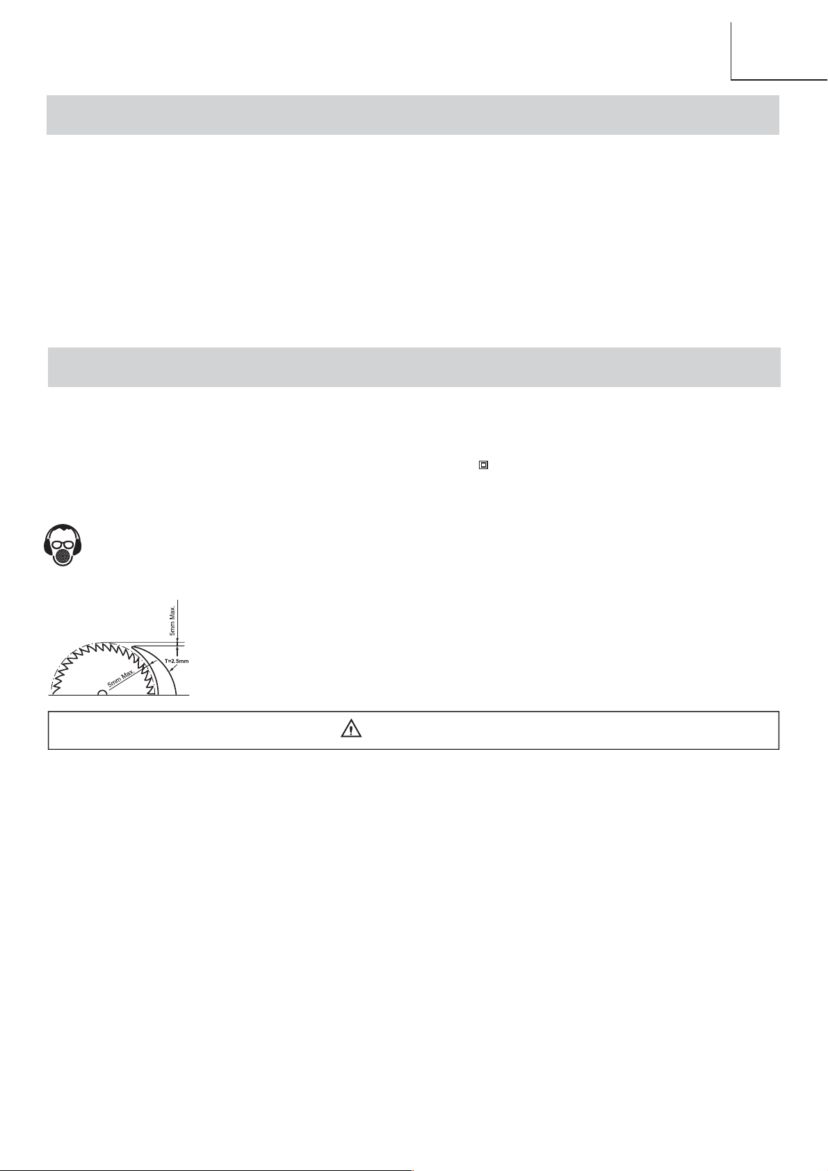
Wear safety goggles
Wear ear protection
Wear a breathing mask
●
Riving knife thickness is 2.5 mm.
●
The maximum radial distance between the riving knife and the toothed rim of the saw
blade is 5 mm.
●
The tip of the riving knife shall not be lower than 5 mm from the tooth peak.
WARNING
● Noise can be a health hazard. When the noise level exceeds 85dB(A), be sure to wear ear protection.
● To avoid electrical hazards, fi re hazards or damage to the table saw, use proper circuit protection. This
table saw is wired at the factory for 230-240 Volt operation. It must be connected to a 230-240 Volt / 6.5
Ampere time delay fuse or circuit breaker. To avoid shock or fi re, replace power cord immediately if it is
worn, cut or damaged in any way. Before using your table saw, it is critical that you read and understand
these safety rules. Failure to follow these rules could result in serious injury to you or damage to the table
saw.
● Through poor conditions of the electrical MAINS, shortly voltage drops can appear when starting the
EQUIPMENT. This can infl uence other equipment (e.g. blinking of a lamp). If the MAINS-IMPEDANCE Zmax <
0.3 OHM, such disturbances are not expected. (In case of need, you may contact your local supply authority
for further information).
– 3 –
Page 4

English
GENERAL SAFETY RULES
WARNING
When using electric tools basic safety precautions should always be followed to reduce the risk of fi re, electric
shock and personal injury.
Read all these instructions before attempting to
operate your product. Save these instructions for future
reference.
1. KEEP WORK AREA CLEAR. Cluttered areas and
benches invite injuries.
2. CONSIDER WORK AREA ENVIRONMENT. Do not
expose tools to rain. Do not use tools in damp or wet
locations. Keep work area well lit. Do not use tools in
the presence of fl ammable liquids or gases.
3. GUARD AGAINST ELECTRIC SHOCK. Avoid body
contact with earthed or grounded surfaces.
4. KEEP OTHER PEOPLE AWAY. Do not let others,
especially children, not involved in the work touch the
tool or the extension lead and keep them away from
the work area.
5. STORE IDLE TOOLS. When not in use, tools should
be stored in a dry locked-up place, out of reach of
children.
6. DO NOT FORCE THE TOOL. It will do the job better
and safer at the rate for which it was intended.
7. USE THE RIGHT TOOL. Do not force small tools
to do the job of a heavy duty tool. Do not use tools
for purposes not intended; for example do not use
circular saws to cut tree limbs or logs.
8. DRESS PROPERLY. Do not wear loose clothing
or jewellery, they can be caught in moving parts.
Non-skid footwear is recommended when working
outdoors. Wear protective hair covering to contain
long hair.
9. USE PROTECTIVE EQUIPMENT. Use safety
glasses. Use face or dust mask if cutting operations
create dust.
10. CONNECT DUST EXTRACTION EQUIPMENT.
If devices are provided for the connection of dust
extraction and collecting equipment, ensure these are
connected and properly used.
11. DO NOT ABUSE THE CABLE. Never pull the cable
to disconnect it from the socket. Keep the cord away
from heat, oil and sharp edge.
12. SECURE WORK. Where possible use clamps or a
vise to hold the work. It’s safer than using your hand.
13. DON’T OVERREACH. Keep proper footing and
balance at all time.
14. MAINTAIN TOOLS WITH CARE. Keep cutting tools
sharp and clean for better and safer performance.
Follow instructions for lubricating and changing
accessories. Inspect tool cords periodically and
if damaged have them repaired by an authorized
service facility. Inspect extension cords periodically
and replace if damaged. Keep handles dry, clean and
free from oil and grease.
15. DISCONNECT TOOLS. When not in use, before
servicing and when changing accessories such as
blades, bits, cutters, disconnect tools from the power
supply.
16. REMOVE ADJUSTING KEYS AND WRENCHES.
Form the habit of checking to see that keys and
adjusting wrenches are removed from the tool before
turning it on.
17. AVOID UNINTENTIONAL STARTING. Ensure switch
is in “off” position when plugging in.
18. USE OUTDOOR EXTENSION LEADS. When the
tool is used outdoors, use only extension leads
intended for outdoor use and so marked.
19. STAY ALERT. Watch what you are doing, use
common sense and do not operate the tool when you
are tired.
20. CHECK DAMAGED PARTS. Before further use of
the tool, it should be carefully checked to determine
that it will operate properly and perform its intended
function. Check the alignment of moving parts,
binding of moving parts, breakage of parts, mounting
and any other conditions that may affect its operation.
A guard or other part that is damaged should be
properly repaired or replaced by an authorized service
centre unless otherwise indicated in this instruction
manual. Do not use the tool if the switch does not turn
it on and off.
21. WARNING. The use of any accessory or attachment
other than one recommended in this instruction
manual may present a risk of personal injury.
22. HAVE YOUR TOOL REPAIRED BY A QUALIFIED
PERSON. This electric tool complies with the relevant
safety rules. Repairs should only be carried out by a
qualifi ed person using original spare parts, otherwise
this may result in considerable danger to the user.
– 4 –
Page 5

English
TABLE SAW SAFETY
1. Do not use saw blades which are High Speed Steel (HS) or damaged or deformed.
2. Replace the table insert when worn.
3. Use only saw blades recommended by the manufacturer which confi rms to EN847-1, with warning that the riving knife
shall not be thicker than the width of the groove cut by the saw blade and not thinner than the body of the saw blade.
4. Select saw blades in relation to the material to be cut.
5. Use push-sticks to feed the workpiece past the saw blade. The push-stick or push block should always be stored with
the machine when not in use.
6. Connect your table saw to a dust collecting device when sawing (Dust chute diameter 58 mm).
7. Use and correct adjustment of the riving knife.
8. Use and correct adjustment of the upper saw blade guard.
9. Wear ear protection.
10. Always take care when slotting, saw shall not be used for slotting.
11. Not for cutting metal, timber or round log.
– 5 –
Page 6

English
ELECTRICAL REQUIREMENTS AND SAFETY
CONNECTING TO THE POWER SUPPLY
Check that the power supply and plug used is in accordance with your table saw. Have a look at the rating plate of the
motor or the rating on the table saw. Any changes should always be carried out by a qualifi ed electrician.
WARNING
Avoid contact with the terminals on the plug when installing (removing) the plug to (from) the power supply
outlet. Contact will cause a severe electrical shock.
USING AN EXTENSION LEAD
The use of any extension lead will cause some loss of power. To keep this to a minimum and to prevent overheating
and motor burn-out, ask advice from a qualifi ed electrician to determine the minimum wire size of the extension lead.
– 6 –
Page 7
ACCESSORIES AND ATTACHMENTS
RECOMMENDED ACCESSORIES
WARNING
Visit your Hardware Department or see the Power and Hand Tools Catalog to purchase recommended
accessories for this power tool.
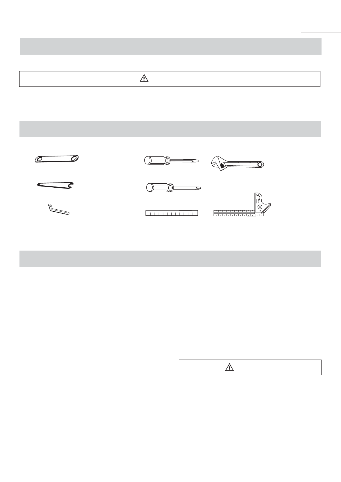
TOOLS NEEDED FOR ASSEMBLY
English
Supplied
Blade Wrench
Blade Wrench
4 mm Hex Wrench
Not Supplied
Medium Screwdriver
#2 Phillips Screwdriver
Straight Edge
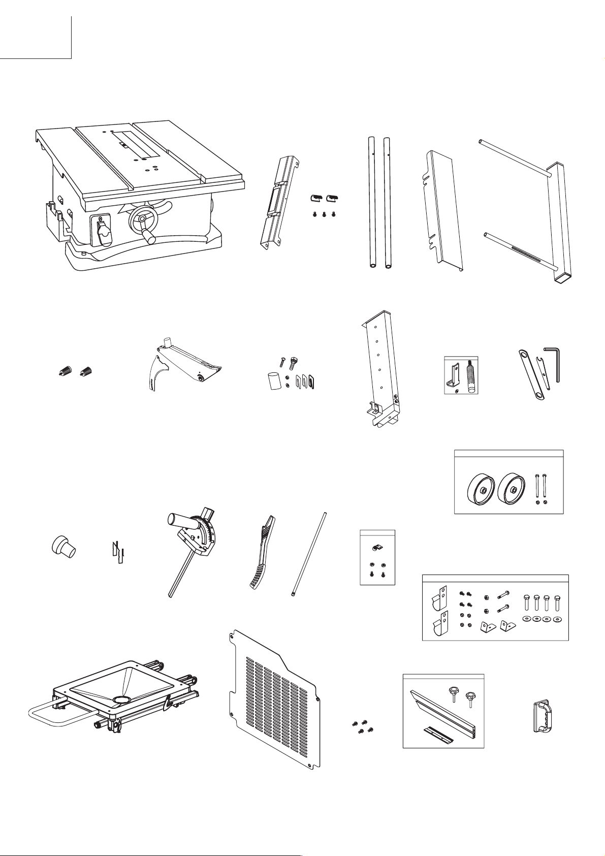
CARTON CONTENTS
UNPACKING AND CHECKING CONTENTS
Separate all parts from packing materials. Check each
part with the illustration on the next page and the “Table
of Loose Parts” to make certain all items are accounted
for, before discarding any packing material.
Table of loose parts
ITEM DESCRIPTION QUANTITY
A Table saw assembly 1
B Rear table extension 1
Table extension hardware bag
C
D Rear table extension tube 2
E Extension fence 1
F Extension fence locking handle 2
G Riving knife assembly 1
H Riving knife hardware bag 1
I Rip fence 1
J Rip fence hardware bag 1
K Wrench bag 1
L Dust adapter 1
M Push stick storage 1
1
Adjustable Wrench
Combination Square
N Mitre gauge 1
O Push stick 1
P Rear support leg 1
Q Rear support leg hardware bag 1
R Roller wheel hardware bag 1
S Stand hardware bag 1
T Stand assembly 1
U Base cover 1
V Screw 4
W Right side table extension 1
X Auxiliary fence and hardware bag 1
Y Push block 1
WARNING
If any part is missing or damaged, do not attempt
to assemble the table saw, plug in the power cord,
or turn the switch ON until the missing or damaged
part is obtained and is installed correctly.
NOTE: To make assembly easier, keep contents of box
together. Apply a coat of automobile wax to the table.
Wipe all parts thoroughly with a clean dry cloth. This will
reduce friction when pushing the workpiece.
– 7 –
Page 8
English
UNPACKING YOUR TABLE SAW
C
A
F
G
B
D
H
I
E
J
W
K
R
L
M
O
N
T
U
P
– 8 –
Q
S
V
X
Y
Page 9
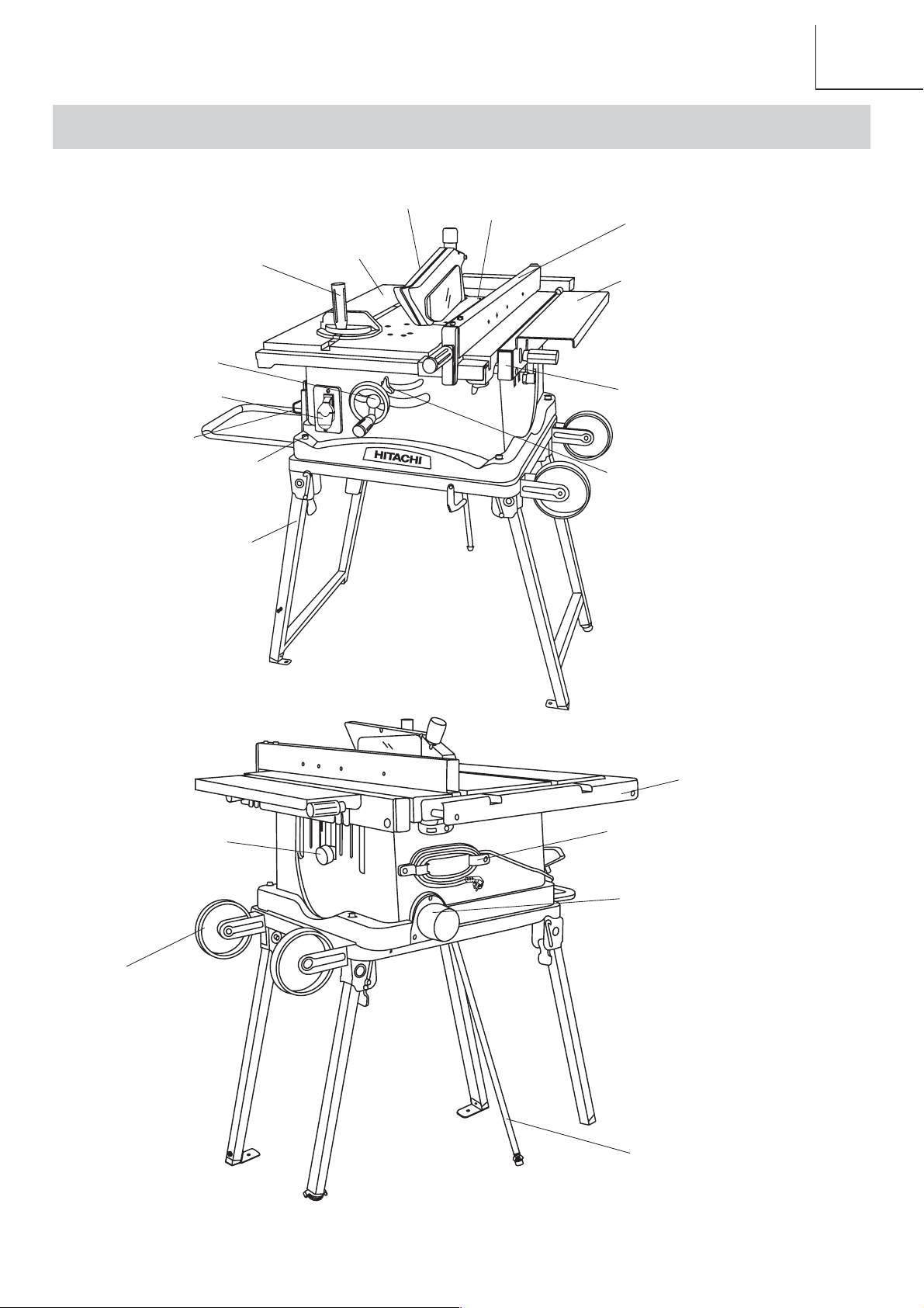
KNOW YOUR TABLE SAW
English
Handwheel
ON/OFF switch
Push-stick storage
Mounting holes
Stand assembly
Mitre gauge
Upper blade guard
Table
Table insert
Rip fence
Right side table extension
Extension fence
Saw blade tilt lock handle
Blade storage
Roller wheel
Rear table extension
Power cord storage
Dust port
Support leg
– 9 –
Page 10

English
ASSEMBLY AND ADJUSTMENTS
ESTIMATED ASSEMBLY TIME 25~40 MINUTES
STAND ASSEMBLY (FIG. A)
1. Release the stand hook (1) by sliding it to the left.
2. Unfold the wider leg set (2) on the left side of the
stand. Pull the stand locking lever (3) downward and
push down to lock in place.
3. Lift the stand up and unfold the narrower leg set (4)
on the right of the saw.
4. Pull the right side stand locking lever downward and
push to lock in place.
NOTE: Make sure the stand is locked securely.
5. Attach one roller wheel (6) to roller wheel mounting
bracket using a square neck bolt (7) and nut (8) as
shown. Repeat for other wheel.
6. Attach two L-Type clamps (9) to the front legs with
two screws (10) and nuts (11).
INSTALLING REAR SUPPORT LEG (FIG. A)
1. Install connector (A) onto bottom of stand with two
Phillips screws (long) and lock nuts.
2. Install two storage hooks (B) onto the back of the
stand using two Phillips screws (short) and lock nuts
per hook.
3. Thread rear support leg (C) into connector (A).
4. To level rear support leg to the fl oor, adjust the
leveling foot until it touches the fl oor and provides
stability to the stand and secure in position by
locking the nut against the bottom of the rear
support leg.
5. When transporting the unit, unscrew the rear support
leg and position in the hooks for storage.
Fig. A
ASSEMBLE BASE COVER TO TABLE SAW (FIG. B)
NOTE:
Your saw is supplied with the base cover
unassembled.
1. Assemble the base cover (1) to the saw base (2) by
using the 4 screws (3) in the loose parts bag supplied.
2. Tighten the 4 screws (3) before mounting the saw on
the stand.
Fig. B
2
1
3
3
ASSEMBLING THE TABLE SAW TO STAND (FIG. C)
1. Place stand on level surface and adjust the leveling
foot (1) on the right rear leg of stand to stabilize.
2. Place table saw on the top of stand aligning the
mounting holes in base with mounting holes in stand.
3. Place four fl at washers onto four hex. head bolts (2).
Place them through the base mounting holes and
thread into the stand mounting holes and tighten all
four bolts securely.
3
3
Fig. C
1
7
B
4
5
C
6
8
2
2
10
9
11
A
3
– 10 –
2
1
Page 11

English
FOLDING THE TABLE SAW/STAND (FIG. D)
1. Rotate the stand locking hook to the left. Lift up on the
two right side stand locking levers to unlock and lift the
right of table saw up slightly off the fl oor, fold up the
narrower leg set on the right side up to the base of the
saw until it snaps into position with the spring clip.
2. Rest the right side of the saw back onto the fl oor,
release the two left side stand locking levers and tilt
the saw on it right side, then fold the left side leg set
up to the base.
3. Secure the stand legs into position by rotating the
stand locking hook to the right.
Fig. D
STORAGE (FIG. E, F)
RIP FENCE AND MITER GAUGE (FIG. E)
Storage brackets for the rip fence (2) and miter gauge
(3) are located on the left side of the saw housing.
BLADE (FIG. F)
1. Loosen and remove the knob (1) on the right side of
the saw housing.
2. Place extra blades onto the arbor. Replace the knob
and tighten.
Fig. F
1
SETTING UP THE TABLE SAW/STAND (FIG. D)
1. Release the stand hook by sliding it to the left.
2. Unfold the wider leg set (left side) and lock the stand
locking lever in place by sliding the lever down the
slots of the mounting bracket and push downward to
lock in place.
3. Rest the left side of the saw onto the fl oor and lift up
on the right side of the stand and unfold the narrower
leg set.
4. Secure the right side legs into position by locking the
stand locking lever in place.
NOTE: Make sure the saw is locked in position as
instructed before operation
WARNING
For your own safety, never connect the plug to
power source outlet until all assembly steps are
completed and you have read and understood the
safety and operational instructions.
INSTALLING THE PUSH STICK AND PUSH BLOCK
STORAGE (FIG. E)
Attach the push stick and push block storage (1) into the
left side of the body shell.
Fig. E
1
3
INSTALL THE AUXILIARY FENCE INTO THE RIP
FENCE (FIG. G, H)
NOTE:
A auxiliary fence should be used when ripping material
such as thin paneling to prevent the material from
catching between the bottom of the fence and the table.
When performimg some special cutting operations, you
can add a auxiliary fence (2) to the either side of the rip
fence (3).
1. Slide the rail (1) into the auxiliary fence (2).
Fig. G
2. Align the holes in the rip fence (3) and with the holes
in the rail (1).
3. Insert the lock knob (4) through the aligned holes and
tighten.
Fig. H
2
2
1
3
4
1
2
– 11 –
Page 12

English
INSTALLING THE DUST PORT ADAPTER (FIG. I)
NOTE: A 58-37 mm dust port adapter is optional for your
convenience.
1. Attach the dust port adapter (2) to the dust port (1).
Fig. I
2
1
BLADE GUARD ASSEMBLY (FIG. J)
1. Place the blade guard on the riving knife and secure
it with the bolt (1), fl at washer (2), and nut (3).
2. Place the plunger (7) to the exhaust port of the blade
guard
INSTALLING THE CLAMP HANDLE (FIG. K)
1. Thread the clamp handle (1) through the washer (2),
pressing plate (3) into the hole (4) of the rip fence
and lock in place by tighten the nut (5) against the
fence head.
Fig. K
3
INSTALLING THE RIP FENCE (FIG. L)
Slide in the rip fence assembly from the end of the table
with aligning the groove in the front of the table and the
tongue on the fence bracket.
Fig. L
4
5
1
2
INSTALLING THE RIVING KNIFE (FIG. J)
WARNING
The riving knife thickness of 2.5 mm. Make sure the
blade and riving knife are aligned on the same line.
If not, adjust the riving knife by loosening the knob
bolts. It should be less than 5 mm at all positions.
1. Rise the blade to its highest position by turning the
handwheel and tilt the blade to 45° bevel angle.
2. Loosen the screws on the table insert and remove the
table insert.
3. Place the knob bolt (4) on the riving knife bracket (5)
and the riving knife (6).
4. Tighten the knob bolt (4).
5. Replace the table insert and tighten the screw.
6.
Fig. J
5
7
3
2
1
6
6
4
CHANGING BLADES (FIG. M)
WARNING
To avoid injury from accidental starting, always turn
the switch off (“0”) and remove the power plug from
the power source before changing the blades.
1. Loosen the screws on the table insert by a
screwdriver and remove the table insert.
2. Loosen the screw (5) and remove the plate (6).
3. Raise the saw blade to its maximum height.
4. Use the supplied open end wrench (1) to keep the
arbor from turning and the supplied box-end wrench
(2) to loosen the arbor nut. (Fig. M)
5. Remove the arbor nut (3) and outer fl ange (4).
6. Replace the saw blade. Make sure the teeth of the
blade point down at the front of the table.
7. Assemble the arbor fl ange and arbor nut back to the
saw arbor and tighten the arbor nut.
8. Replace the plate (6) and tighten the screw (5).
9. Replace the table insert and retighten the two screws.
– 12 –
Page 13

English
Fig. M
2
1
5
4
3
6
INSTALLING TABLE SIDE EXTENSION (FIG. N)
1. Identify the right hand table extension.
NOTE: The right hand table extension is the one with
the measuring scale (1) visible from the front of the
saw when it is installed to the right hand side of the
saw table.
2. Open both front and rear cam locking levers (2) on
the right hand side of the saw base by pulling them
out from the cam locking assemblies (4).
3. Insert the table extension mounting tubes (3) into the
two matching holes in the cam lever assemblies.
NOTE: Make sure the front mounting tube has the
measuring scale visible from the front of the saw.
4. Slide the table extension toward the table until it rests
against the saw table.
5. Lock both cam locking levers by pushing them in
toward the cam locking lever assemblies.
6. Drive a screw (5) into the end of the rear right hand
table extension tube (6) as a stop.
4. Drive screws (5) into the end of the rear table
extension tubes (2) as a stop.
Fig. O
1
2
4
TABLE EXTENSION RIP FENCE POSITIONING
(FIG. P, Q)
NOTE: For ripping workpiece widths between 140 mm
and 250 mm in width, the right side extension rip fence
must be installed in the IN-RIP position. (Fig. P)
For ripping workpiece widths between 250mm and
610mm in width, the extension rip fence must be
installed in the OUT-RIP position. (Fig. Q)
IN-RIP TABLE EXTENSION RIP FENCE
INSTALLATION (FIG. P)
1. Install two table extension fence locking handles (1)
on the right side table extension (2).
NOTE: Do not turn locking handles all the way in.
2. Place the table extension fence (3) on the table
extension through the small locating slots.
3. Adjust rip fence up or down until the bottom edge of
the rip fence just clears the saw table.
4. Tighten the locking handles.
3
2
5
Fig. N
7
6
5
4
INSTALLING REAR TABLE EXTENSION (FIG. O)
1. Place the rear table extension (1) onto the two rear
table extension tubes (2).
2. Snap two location seats (3) over the two rear table
extension tubes (2).
3. Insert rear table extension tubes (2) into the two holes
in the rear of the saw table (4) and into extenson tube
brackets under the table. Position rear table support
so instruction labels are up.
1
2
3
Fig. P
1
3
2
OUT-RIP TABLE EXTENSION RIP FENCE
INSTALLATION (FIG. Q)
1. Loosen two table extension fence locking handles (1).
NOTE: Do not turn locking handles all the way in.
2. Place the table extension fence (3) on the table
extension (2) through the large locating slots.
3. Raise the fence to the desired height and tighten the
locking handles.
– 13 –
Page 14

English
Fig. Q
3
1
2
STORING THE TOOL (FIG. R)
NOTE: Folding the stand and storage when it is not in
use.
1. Release two table extension fence locking handles (1)
on the right side table extension (2).
2. Place the table extension fence (3) opposite on the
table extension through the large locating slots.
3. Adjust rip fence until the fence fl ush with the saw
table.
4. Tighten the locking handles (1) and cam lock levers
(4).
5. Follow the procedures as “Folding the Table Saw/
Stand”.
6. Place the tool as shown.
Fig. R
4
Fig. S
ADJUSTING RIP FENCE (FIG. T)
4
3
4
1
2
WARNING
This adjustment must be correct or kickback could
result and accurate cuts cannot be made.
1. Loosen the clamp handle (1).
2. Position the rip fence at one edge of the mitre gauge
groove.
3. Lock the rip fence to the table using the clamp handle.
The edge of the rip fence should then line up parallel
with the mitre gauge groove.
4. If the edge of the rip fence is not parallel with the
mitre gauge groove, loosen the clamp handle (1),
while holding the fence bracket against the front of
the saw table, move the rear end of the fence until it is
parallel with the mitre gauge groove, then tighten the
bolts (2) and the clamp handle.
2
3
1
ADJUSTING THE RIVING KNIFE (FIG. S)
1. If the blade and riving knife are not correctly aligned:
a. Remove the table insert by removing the screws.
b. Remove the blade guard by removing the bolt,
fl at washer and nut that lock the guard in place.
c. Loosen the bolt (1) from the riving knife bracket
(2).
2. Insert spacers (3) between the riving knife (4) and
bracket (2).
3. Retighten the guard mounting bolt (1) securely.
4. Replace the blade guard assembly using the bolt
and nut.
5. Check the riving knife and blade alignment again at
both 90° and 45°.
6. Add or remove the spacers until the alignment is
correct.
7. Replace the table insert.
ADJUSTING THE POINTER OF RIP FENCE (FIG. T)
NOTE: The pointer will need to be readjusted whenever
a different thickness saw blade is installed.
1. To adjust pointer 0 setting, loosen the clamp handle (1)
and move the rip fence to bring it into tight contact with
the side of the saw blade.
2. Make sure that the pointer (3) points to 0 on the scale
in the front of table.
3. If the pointer does not point to 0 on the scale, tighten
the clamp handle, loosen the pointer screw (4) and
adjust the pointer to the 0 position and retighten the
pointer screw.
2
Fig. T
3
4
1
– 14 –
Page 15

English
ADJUSTING REAR TABLE EXTENSION (FIG. U)
1. Rear table extension (1) should be positioned as close
as possible to the rear of the table (2) when ripping
short workpieces.
2. Rear table extension (1) should be pulled out fully until
the stop screw (3) prevent it from moving outward
when ripping long workpieces that require extra
support as you are completing the cut.
Fig. U
1
2
3
ADJUSTING TABLE SIDE EXTENSION (FIG. V)
1. Open both front and rear cam locking levers (1) on
the table extension to be adjusted by pulling them out
from the cam locking assemblies (2).
2. Slide the table extension (3) in or out to the desired
position.
NOTE: Use the width scale located on the front
table extension tube to verify the approximate rip
width desired.
3. Assembly table extension rip fence to IN-RIP or
OUT- RIP position.
4. Make fi nal width adjustment and lock cam locking
levers.
NOTE: Rip a scrap piece of material to verify rip
width.
Fig. V
3
ADJUSTING THE BLADE PARALLEL TO THE MITRE
GAUGE GROOVE (FIG. W, X, Y)
WARNING
This adjustment must be correct or kickback could
result and accurate cuts cannot be made.
NOTE: This tool is accurately adjusted before shipping
from the factory. Check the following accuracy and
readjust them if necessary in order to obtain the best
results in operation.
1. Raise the blade to its highest position and set it to 0°
bevel angle.
2. Select a tooth on the saw blade which is bent to the
right. Mark that tooth with a pencil or permanent
marker.
3. Place the mitre gauge in the right hand groove on the
table top. Set the mitre gauge to 90° and tighten the
gauge handle to lock it in that position.
4. Rotate the blade to bring the marked tooth in the front
and about 13 mm above the table top. Place the bar
of square fl at against the mitre gauge and move the
bar toward the saw blade until it just touches the tip of
the marked saw blade tooth. (Fig. W)
Fig. W
5. Without disturbing the bar clamped to the mitre
gauge (1), move the mitre gauge to the centre of the
saw blade. Rotate the blade so the marked tooth is at
the rear and about 13 mm above the table top.
6. Slide the mitre gauge rearward until the clamped bar
is closest to the tip of the marked tooth. (Fig. X)
Fig. X
1
2
1
– 15 –
Page 16

English
7. If the bar just touches the tooth when the gauge was
in the front position, it should touch the tooth in the
rear position.
8. If the front and rear clearance are not identical,
remove the mitre gauge, loosen four screws (1)
and carefully grasp the saw blade. Make necessary
correction until measurements taken at the front and
rear are identical. Tighten the four screws (1). (Fig. Y)
Fig. Y
1
2
3
ADJUSTING 90° POSITIVE STOP OF BLADE
(FIG. Y, Z)
1. Raise the saw blade to its maximum height.
2. Loosen the saw blade tilt lock handle and move the
saw blade tilting mechanism to the left until it hits
against the stopper. Then tighten the saw blade tilt
lock handle.
3. Use a square (1) to check the saw blade is at 90°.
(Fig. Z)
4. If the saw blade is not at 90°, loosen the saw blade
tilt lock handle. Adjust the screws (2-Fig. Y) a few
turns and move the saw blade tilting mechanism until
the blade is at 90° to the table.
5. Tighten the saw blade tilt lock handle after
adjustment.
6. Loosen the screw of the tilt pointer and set the
pointer to 0°.
ADJUSTING 45° POSITIVE STOP OF BLADE
(FIG. Y, Z)
1. Raise the saw blade to its maximum height.
2. Loosen the saw blade tilt lock handle and move the
saw blade tilting mechanism to the right until it hits
against the stopper. Then tighten the saw blade tilt
lock handle.
3. Use a 45° gauge (2) to check the saw blade is at 45°.
(Fig. Z)
4. If the saw blade is not at 45°, loosen the saw blade
tilt lock handle. Adjust the screws (3-Fig. Y) a few
turns and move the saw blade tilting mechanism until
the blade is at 45° to the table.
5. Tighten the saw blade tilt lock handle after adjustment.
6. Loosen the screw of the tilt pointer and set the pointer
to 45°.
ADJUSTING THE MITRE GAUGE (FIG. AA)
1. To adjust pointer 90° setting, loosen the clamp handle
(1) and place a square (2) against both the saw blade
(3) and mitre gauge (4). The pointer (5) should indicate
90° on the mitre gauge.
2. If the pointer does not point to 90° on the mitre gauge,
tighten the clamp handle, loosen the pointer screw (6)
on the bar, adjust the pointer to the 90° position and
retighten the pointer screw.
Fig. AA
2
4
3
1
Fig. Z
5
1
2
– 16 –
6
Page 17

OPERATION
WARNING
Never connect the plug to the power source outlet
until all installations and adjustments are completed
and you have read and understood the safety and
operational instructions. Remove the safety key
whenever the table saw is not in use. Place it in a
safe place and out of reach of children.
“ON/OFF” SWITCH (FIG. BB)
The keyed switch is intended to prevent unauthorized
use of the table saw.
1. To turn the table saw ON insert the safety key (1)
into the key slot in the centre of the switch.
2. Push the key fi rmly into the slot, then push switch to
the ON position to start the table saw.
3. To turn the table saw OFF push the switch to the
down position.
4. Remove safety key when table saw is not in use to
prevent unauthorized usage.
RAISING AND LOWERING THE SAW BLADE
(FIG. BB)
WARNING
Never operate while saw blade rotating.
1. To raise the saw blade, rotate the handwheel (2)
anticlockwise.
2. To lower the saw blade, rotate the handwheel (2)
clockwise.
NOTE: The saw blade height is recommended about
3.2 mm above the top of the workpiece.
English
1. Loosen the front and rear cam locking levers (7).
2. Slide the extension table out to the desired position.
3. Loosen the fence locking handles (6), and raise or
lower the fence as needed.
4. Tighten all fence locking handles and cam locking
levers.
MOVING THE RIP FENCE (FIG. BB)
NOTE:
1. The rip fence (5) can be used on either side of the
saw blade.
2. The pointer on the rip fence indicates the distance
between the saw blade and rip fence.
3. To move the rip fence (5), loosen the clamp handle (8)
while pressing the fence bracket against the table
surface and set the desired distance from the saw
blade, retighten the clamp handle.
OPERATING THE MITRE GAUGE (FIG. BB)
NOTE:
1. The mitre gauge (4) can be used on either side of the
saw blade.
2. Because the mitre gauge groove is a T-type slot, to
install the mitre gauge, insert the gauge bar from the
end of the groove.
3. To set the mitre cut angle, loosen the clamp handle,
turn the mitre gauge (4) to the desired angle, retighten
the clamp handle.
Fig. BB
3
5
4
TILTING THE SAW BLADE (FIG. BB)
WARNING
Always lock the saw blade tilt lock handle during
operations.
Loosen the saw blade tilt lock handle (3), move the
hand wheel until the saw blade is at the desired angle
and tighten the saw blade tilt lock handle.
USING THE TABLE EXTENSION (FIG. BB)
NOTE: Raise the fence to a position that just clears the
table surface and secure in place using locking handles
for IN-RIP position.
– 17 –
6
1
2
8
7
Page 18

English
FEATHERBOARD (FIG. CC, DD)
A featherboard is a device used to help control the
workpiece by guiding it securely against the table or
fence. Featherboards are especially useful when ripping
small workpieces and for completing non-through cuts.
The end is angled with a number of short kerfs to give a
friction hold on the workpiece and locked in place on the
table with C-clamps. Test that it can resist kickback.
WARNING
Place the featherboard against the uncut portion of
the workpiece to avoid kickback that could cause
serious personal injury.
MAKE A FEATHERBOARD (FIG. CC)
Select a solid piece of lumber approximately
19.05 mm thick, 101.6 mm wide and 457.2 mm long. To
make a featherboard, cut one end of the lumber at 60
degrees, then cut the length of 203.2 mm slots 6.35 mm
apart on the angled end as shown in Fig. CC.
Fig. CC
101.6 mm
19.05 mm
USE A FEATHERBOARD (FIG. DD)
1. Lower the saw blade (1).
2. Position the rip fence (2) to the desired adjustment
and lock the rip fence.
3. Place the workpiece (3) against the fence and over
the saw blade area.
4. Adjust the featherboard (4) to resist to the workpiece
forward of the blade.
5. Attached the C-clamps (5) to secure the featherboard
to ht eedge of the table.
Fig. DD
3.18 mm
6.35 mm
457.2 mm
76.2 mm
203.2 mm
1
3
2
RIPPING (FIG. EE)
NOTE:
●
Generally ripping is cutting with the grain.
●
Do not perform ripping “free hand”. Use the rip fence (1)
for ripping and remove the mitre gauge from the table.
●
Push stick (2) is the device used for safely pushing a
workpiece through the blade. To make an additional
push stick, refer to the drawing of the push stick
construction on page 23.
●
A push block (3) has a handle fastened by recessed
screws from the underside. Use it on non-through
cuts. Be sure the screws in a push block are recessed
to avoid damaging the saw or workpiece.
●
Always use a push stick. When width of the rip is
narrow than 50 mm the push stick cannot be used
because the guard will interfere...therefore, use the
auxiliary fence so the push stick can be used.
WARNING
1. Before ripping, confi rm the following items:
a. Rip fence is securely fi xed and parallel to the
saw blade.
Riving knife is properly aligned with the saw
b.
blade.
c. The workpiece must have a straight edge
against the rip fence and must not be warped,
twisted or bowed.
2. Keep both hands away from the saw blade and
away from the path of the saw blade.
3. The use of push block, push stick and
featherboard are necessary when making nonthrough cuts.
1. Adjust the saw blade height so it is about 3.2 mm
above the top of the workpiece.
2. Hold the workpiece fl at on the table and against the
rip fence. Keep the workpiece about 25 mm away from
the saw blade.
3. Turn on the switch and allow the saw blade to come
up to speed.
Fig. EE
1
2
5
3
4
– 18 –
Page 19

English
4. Keep the workpiece against the table and rip fence,
slowly feed the workpiece rearward all the way through
the saw blade. Continuously push the workpiece until
it passes the blade guard and clears the rear of the
table.
5. When ripping long boards or large panels, always use
an adequate support.
6. When the width of rip is more than 150 mm, feed the
workpiece with one or both hands continuously until it
is beyond the saw blade and riving knife.
WARNING
Do not push the free piece that is cut off, merely
guide it.
7. When the width of rip 50 mm to 150 mm wide, use
the supplied push stick to feed the workpiece.
8. When perform bevel ripping, only work with the work
piece and rip fence on the right side of the saw blade.
CROSSCUTTING (FIG. FF)
NOTE:
1. Generally cross cutting is cutting across the grain.
2. Do not perform cross cutting “free hand”. Use the
mitre gauge for cross cutting and remove the rip fence
from the table.
WARNING
1. Before cross cutting, confi rm the following
items:
a. Riving knife is properly aligned with the saw
blade.
b. The workpiece must have a straight edge
against the mitre gauge and must not be
warped, twisted or bowed.
2. Keep both hands away from the saw blade and
away from the path of the saw blade.
5. When perform bevel cross cutting, only work with the
workpiece and mitre gauge on the right side of the
saw blade.
Fig. FF
3
BEVEL CROSSCUTTING (FIG. GG)
This cutting operation is the same as crosscutting except
the blade is at bevel angle other than 0°.
2
1
WARNING
Always work to the right side of the blade during this
type of cut. The mitre gauge (3) must be in the right
side groove (2) because the bevel angle may cause
the blade guard to interfere with the cut if used on
the left side groove.
1. Lower the blade to the lowest position.
2. Loosen the blade bevel lock knob and adjust the
blade (1) to the desired angle.
3. Tighten the blade bevel lock knob.
4. Raise the blade to the desired height.
NOTE: The maximum cut depth at 45
5. Tighten mitre lock handle at 90°.
6. Hold workpiece fi rmly against the face of the mitre
gauge (3) throughout the cutting operation.
0
is 55 mm.
1. Adjust the saw blade height so it is about 3.2 mm
above the top of the workpiece.
2. Hold the workpiece fl at on the table and against the
mitre gauge. Keep the workpiece about 25 mm away
from the saw blade.
3. Turn on the switch and allow the saw blade (1) to
come up to full speed.
4. Keep the workpiece (2) against the table and mitre
gauge (3), slowly feed the workpiece rearward all the
way through the saw blade. Continuously push the
workpiece until it is clear of the blade guard and it falls
off the rear of the table.
– 19 –
Fig. GG
1
32
Page 20

English
mitre gauge throughout the cutting operation.
COMPOUND MITRE CROSSCUTTING (FIG. HH)
This sawing operation is combining a mitre angle with a
bevel angle.
WARNING
Always work to the right side of the blade during
this type of cut. The mitre gauge (3) must be in the
right side groove because the bevel angle may
cause the blade guard to interfere with the cut
if used on the left side groove. When tilting the
workpiece to 45° and push it toward the blade, the
blade guard may hit the blade. To avoid injury, stop
the work at that time.
1. Set the mitre gauge (3) to the desired angle.
2. Place the mitre gauge (3) in the right side groove (2)
of the table.
3. Set the blade (1) bevel to the desired bevel angle
and tighten the blade bevel lock knob.
4. Hold workpiece fi rmly against the face of the mitre
gauge (3) throughout the cutting operation.
Fig. II
3
2
1
Fig. HH
MITRE CUTS (FIG. II)
This sawing operation is the same as crosscutting except
the mitre gauge is locked at an angle other than 90°.
1. Set the blade (1) to 0° bevel angle and tighten the
blade bevel lock knob.
2. Set the mitre gauge (3) at the desired mitre angle
and lock in position by tightening the mitre gauge
locking handle.
3. Hold the workpiece (2) fi rmly against the face of the
1
2
3
– 20 –
Page 21

English
MAINTENANCE
MAINTAINING YOUR TABLE SAW
WARNING
For your own safety, turn the switch off and remove the plug from the power source outlet before maintaining
or lubricating your table saw.
GENERAL MAINTENANCE
Occasionally use a cloth to wipe off chips and dust from the machine. And oil the rotary parts once a month to extend
the tool life. Do not oil the motor.
Brush Inspection
Check the motor brushes after the fi rst 50 hours of use for a new machine or after a new set of brushes have been
installed. After the fi rst check, examine them every 10 hours of use.
When the carbon is worn to 0.2 mm in length or if the spring or shunt wire is burned or damaged, replace both brushes.
If the brushes are found serviceable after removing, reinstall them.
– 21 –
Page 22

English
TROUBLESHOOTING GUIDE
WARNING
To avoid injury from an accidental start, turn the switch OFF and always remove the plug from the power
source before making any adjustments.
●
Consult Hitachi Authorized Service Center if for any reason the motor will not run.
SYMPTOM POSSIBLE CAUSES CORRECTIVE ACTION
Saw will not start. 1. Saw not plugged in.
2. Fuse blown or circuit breaker tripped.
3. Cord damaged.
Does not make accurate 45°
and 90° rip cuts.
Material pinched blade when
ripping.
Saw makes unsatisfactory
cuts.
Material kicked back from
blade.
Blade does not raise or tilt
freely.
Blade does not come up to
speed.
Machine vibrates excessively. 1. Saw not mounted securely to workbench.
Does not make accurate 45°
and 90° crosscuts.
1. Positive stop not adjusted correctly.
2. Tilt angle pointer not set accurately.
1. Rip fence not aligned with blade.
2. Warped wood, edge against fence is not
straight.
1. Dull blade.
2. Blade mounted backwards.
3. Gum or pitch on blade.
4. Incorrect blade for work being done.
5. Gum or pitch on blade causing erratic
feed.
1. Rip fence out of adjustment.
2. Feeding stock without rip fence.
3. Dull blade.
4. The operator letting go of material before
it is past saw blade.
5. Miter angle lock knob is not tight.
1. Sawdust and dirt in raising/tilting
mechanisms.
1. Extension cord too light or too long.
2. Low house voltage.
2. Bench on uneven fl oor.
3. Damaged saw blade.
1. Miter gauge out of adjustment. 1. Adjust miter gauge.
1. Plug in saw.
2. Replace fuse or reset circuit breaker.
3. Have cord replaced by Hitachi
Authorized Service Center.
1. Check blade with square and adjust
positive stop.
2. Check blade with square and adjust to
zero.
1. Check and adjust rip fence.
2. Select another piece of wood.
1. Replace blade.
2. Turn the blade around.
3. Remove blade and clean with
turpentine and coarse steel wool.
4. Change the blade.
5. Clean table with turpentine and steel
wool.
1. Align rip fence with miter gauge slot.
2. Install and use rip fence.
3. Replace blade.
4. Push material all the way past saw
blade before releasing work.
5. Tighten knob.
1. Brush or blow out loose dust and dirt.
1. Replace with adequate size cord.
2. Contact your electric company.
1. Tighten all mounting hardware.
2. Reposition on fl at level surface. Fasten
to fl oor if necessary.
3. Replace blade.
– 22 –
Page 23

PUSH STICK CONSTRUCTION
●
Use good quality plywood or solid wood
●
Use 1/2 in. or 3/4 in. material
●
Push stick MUST be thinner than the width of material being cut
English
Drill Hole For
Hanging
15-3/4 in. (400 mm)
Cut Here To Push
Notch To Prevent
Hand From Slipping
1/2 in. Wood
200 - 30
Cut Here To Push
3/4 in. Wood
0
90
0
– 23 –
Page 24

English
PARTS LIST
10” (255mm) JOBSITE TABLE SAW MODEL NO. C10RC
PARTS LIST FOR SCHEMATIC Always order by I.D. Number
Parts No. I.D. Description Size Qty Parts No. I.D. Description Size Qty
328970 2960 RAIL 1 328978 20V1 PUSH BLOCK 1
726434 08VH CORD CLAMP 1 326853 26BN CR. RE. PAN HD. SCREW M6*1.0-25 1
328971 0B1X BOLT 1 326943 27XL END CAP 2
726438 0B23 SADDLE 1 326947 28G5 DUST COLLECTOR JOINT 1
726439 0B24 SPRING 1 326948 28G6 SWITCH BOX 1
326835 0B25 POINTER BRACKET 1 326951 28GC FLOOR PLATE 1
328972 0B2A NEEDLE POINTER 1 326952 28GD EXTENTION WING 1
326923 0B3W RETAINING CLIP 1 326953 28GE ASSIST-FENCE 1
726446 0B99 SPACER 1 327917 28GH DUST COLLECTOR JOINT 1
726447 0B9C PLUNGER HOUSING 1 326955 28GL EXTENTION WING 1
325696 0B9M STRAP 6 326956 28GM LOCATION SEAT 2
726449 0B9W BRACKET 1 326957 28GN UPPER TUBE 1
326924 0B9Z COMPRESSION SPRING 1 326958 28GP UPPER TUBE 1
325698 0BA1 COMPRESSION SPRING 1 326960 28GR HEX. WRENCH 1
726450 0BA4 SPACER 1 326962 28GT WRENCH 1
726454 0BAC SET NUT 1 326855 28GV ANGLE ROD 1
726464 0CSE POWER CORD CLAMP 2 328418 28KY HANDLE BAR ASS’Y 1
328973 0HDL DUST TUBE 1 326627 28L0 CLAMP HANDLE 1
726473 0J3P HEX. WRENCH 1 726799 28L9 LOCK KNOB 1
726478 0J4F FLAT WASHER φ8*16-2.5 1 328979 28XD UPPER TUBE 2
726479 0J4H FLAT WASHER φ10*30-0.2 2 326965 28YW BOLT CLAMP 2
726488 0J70 FLAT WASHER 1/4*3/4-7/64 1 327918 291T CAP HD. SQ. NECK BOLT 1
726489 0J72 FLAT WASHER 1/4*5/8-1/16 1 726873 293H PUSH BLOCK 1
726490 0J76 FLAT WASHER 1/4*3/4-1/16 4 328980 295Z AUXILIARY PARALLEL BRACKET 1
726493 0J7F FLAT WASHER 5/16*7/8-5/64 1 328981 299L SLIDING BASE 2
326927 0J7K FLAT WASHER 3/8*29/32-5/64 1 726355 29E2 ROCKER SWITCH 1
326928 0J7V FLAT WASHER 5/8*1 3/8-5/64 1 328983 29MC LEAD WIRE ASS’Y 1
726495 0J8D FLAT WASHER 3/8*3/4-5/64 3 328984 29MD LEAD WIRE ASS’Y 1
326625 0J8K FLAT WASHER 1/4*3/4-1/16 1 328985 29VM LOCATION SEAT 1
326840 0J9H SPRING WASHER φ1/4” 6 326979 2DN0 SEGMENT GEAR 1
328974 0JPE HEX. HD. BOLT M6*1.0-20 4 328419 2DVB HEIGHT REGULATING BOLT ASS’Y 1
726535 0JXL HEX. SOC. SET SCREW M10*1.5-12 1 329093 2HZV CAP HD. SQ. NECK BOLT M6*1.0-37 1
325713 0JYN HEX. SOC. COUNTERSUNK HD. SCREW M6*1.0-25 6 326980 2JWW SPACER 1
325714 0K0X HEX. HD. SCREW AND WASHER M6*1.0-16 1 326981 2JWY SPACER 2
726320 0K0Z HEX. HD. SCREW AND WASHER M8*1.25-16 4 328986 2JY1 DUST GASKET 1
726319 0K16 HEX. HD. SCREW AND WASHER M8*1.25-16 1 327920 2KU0 CAUTION LABEL 1
726538 0K25 HEX. SOC. HD. CAP SCREW M5*0.8-20 1 327922 2KU2 TRADE-MARK LABEL 1
726543 0K3G CR. RE. PAN HD. SCREW & WASHER M5*0.8-12 1 327924 2KU4 CAUTION LABEL 1
328975 0K55 CR. RE. COUNT HD. SCREW 1 327925 2KU5 SCALE 1
726549 0K57 CR. RE. COUNT HD. SCREW M5*0.8-16 2 327926 2KU6 SCALE 1
327912 0K7E CR. RE. ROUND WASHER HD. SCREW M5*0.8-6 1 328420 2L42 BLADE 1
326932 0K7H CR. RE. ROUND WASHER HD. SCREW M5*0.8-25 2 328987 2LD1 BRACKET GROUP ASS’Y 1
726558 0K7L CR. RE. ROUND WASHER HD. SCREW M6*1.0-16 2 328988 2LE2 BODY SHELL 1
726561 0K8C CR. RE. COUNT HD. TAPPING SCREW M4*18-10 8 328422 2LG9 CLAMP HANDLE 1
726569 0KA0 CR. RE. PAN HD. TAPPING SCREW M5*12-20 2 328423 2LGT HANDWHEEL ASS’Y 1
326452 0KA3 CR. RE. PAN HD. TAPPING SCREW M4*16-12 1 328424 2LGV MITER GAUGE ASS’Y 1
726570 0KA4 CR. RE. PAN HD. TAPPING SCREW M4*16-16 2 328425 2LGW PARALLEL BRACKET ASS’Y 1
726575 0KCA CR. RE. TRUSS HD. TAPPING SCREW M5*12-12 4 328426 2M96 KNOB 1
726578 0KCY
726579 0KDH CR. RE. PAN HD. SCREW M5*0.8-8 3 328989 2MKA INSERT 1
726580 0KDJ CR. RE. PAN HD. SCREW M5*0.8-12 2 328990 2N4Z MOTOR 1
326846 0KDM CR. RE. PAN HD. SCREW M5*0.8-20 2 328991 2PM2 ARBOR COLLAR 1
726581 0KDR CR. RE. PAN HD. SCREW M5*0.8-10 4 328992 2PMW RIVING KNIFE 1
326847 0KEM CR. RE. PAN HD. SCREW M6*1.0-40 1 328993 2PP3 PLUNGER HOUSING 1
726588 0KHZ CAP HD. SQ. NECK BOLT M6*1.0-12 2 328994 2PPF COVER 1
726590 0KJ5 CAP HD. SQ. NECK BOLT M6*1.0-80 1 328995 2PPK ARBOR COLLAR (INNER) 1
726596 0KMR HEX. NUT M5*0.8 T=4 6 328996 2PSP RUBBER INSERT 1
726597 0KMS HEX. NUT M6*1.0 T=5 1 329094 2PSZ DUST COLLECTOR 1
726600 0KMV HEX. NUT M10*1.5 T=8 2 328998 2PT7 BLADE GUARD ASS’Y 1
726601 0KMW HEX. NUT M10*1.5 T=4 1 328999 2PT8 SPLITTER BRACKET ASS’Y 1
726603 0KMY HEX. NUT M8*1.25 T=6.5 2 329000 2PTL KNOB 2
726612 0KQJ CROWN NUT M8*1.25 T=12 1 329001 2PUF TABLE 1
726616 0KQX NUT M6*1.0 T=6 1 329002 2PUG HOLE COVER 1
726620 0KRQ SERRATED TOOTHED HEX. FLANGE NUT M6*1.0 T=6 9 329003 2Q4C INSTRUCTION MANUAL 1
726622 0KRX HEX. NUT AND FLAT WASHER M6*1.0 1 329016 2Q4Q LABEL 1
326427 0KTD STRAIN RELIEF 2 329051 2Q4R LABEL 1
328976 0KTP CABLE CLAMP 1 329052 2Q4T WARNING LABEL 1
326850 0LN4 WIRE CONNECTOR 1 327927 Y2Q2 GUARD-CORD 1
326851 0LVP FERRITE CORE 1 329004 Y407 FLAT WASHER φ6×φ12 T=1 1
326852 0M0H CAPACITOR 1 327931 Y40C FLAT WASHER 3
726644 0T00 SLIDING BASE ASS’Y 2 329005 Y41D C-RING 1
326605 10GV POINTER 1 329006 Y4A7 CARRIAGE BOLT 1
328977 160F SWITCH COVER 1 329007 Y4KF POWER CABLE 1
327914 20L1 SLOTTED PAN HD. SCREW M6*1.0-25 2 329008 Y6H2 PLUNGER 1
726656 20LW CR. RE. PAN HD. SCREW & WASHER M5*0.8-16 3
CR. RE. PAN HD PLAIN WASHER TAPPING SCREW
M5*0.8-12 8 329048 2MJA WARNING STICK LABEL 1
– 24 –
Page 25

English
10” (255mm) JOBSITE TABLE SAW MODEL NO. C10RC
OPER
MANUAL
A
T
OR
’
S
– 25 –
Page 26

English
10” (255mm) JOBSITE TABLE SAW MODEL NO. C10RC
PARTS LIST FOR MOTOR
Parts no. I.D. Description Size Qty
329009 2993 FIELD ASS’Y 1
329010 2997 BRACKET 1
726469 0HVX BALL BEARING 1
326905 0HX9 NEEDLE BEARING 1
329011 0JE0 C-RING 1
326984 0JEE C-RING 1
329012 0JG7 PARALLEL KEY 1
326907 0JX3 HEX. SOC. SET SCREW M5*0.8-8 2
326908 0K3A CR. RE. PAN HD. SCREW & WASHER M5*0.8-30 4
326427 0KTD STRAIN RELIEF 1
326910 0QM2 BRUSH HOLDER ASS’Y 2
326458 0QQU CARBON BRUSH ASS’Y 2
326243 0QR0 BRUSH COVER 2
326911 0R1S BEARING BUSHING 1
326912 0R20 BAFFLE 1
326990 0R24 HELIX GEAR 1
329013 10ZS COLLAR 1
329014 146W CR. RE. PAN HEAD TAPPING & WASHER SCREW M5*12-60 2
326914 28TR RETAINING CLIP 1
329015 29UU ARMATURE ASS’Y 1
326915 2A24 MOTOR HOUSING 1
329017 Y2Q3 BEARING COVER 1
329018 Y2QJ CUTTER SHAFT 1
329019 Y3Z9 BALL BEARING 1
329020 Y3ZY BALL BEARING 1
329021 Y43L CR. RE. COUNT HD. & WAHSER SCREW M4*0.7-12 4
329022 Y4XQ BEARING SEAT 1
– 26 –
Page 27

English
10” (250 mm) JOBSITE TABLE SAW MODEL NO. C10RC
PARTS LIST FOR STAND
Parts No. I.D. Description Size Qty
726357 01AD WING NUT 1
726358 01AE LEVELING PAD 1
726477 0J4E FLAT WASHER φ6*φ13-1 4
726482 0J4W FLAT WASHER φ8.2*18-1.5 4
726503 0JAZ WAVE WASHER WW-6 2
726554 0K7D CR. RE. ROUND WASHER HD. SCREW M6*1.0-10 2
726559 0K7M CR. RE. ROUND WASHER HD. SCREW M6*1.0-18 1
726580 0KDJ CR. RE. PAN HD. SCREW M5*0.8-12 2
726581 0KDR CR. RE. PAN HD. SCREW M5*0.8-10 4
726583 0KDZ CR. RE. PAN HD. SCREW M6*1.0-35 2
726594 0KKU CR. RE. PAN HD. ROUND NECK SCREW M5*0.8-10 1
726597 0KMS HEX. NUT M6*1.0 T=5 3
726610 0KQ4 WING NUT M8*1.25 1
726615 0KQW LOCK NUT M5*0.8 T=5 7
726616 0KQX NUT M6*1.0 T=6 4
726617 0KQY LOCK NUT M8*1.25 T=8 6
726665 213T ROLLING WHEEL 2
726673 22FZ CAP HD. SQ. NECK BOLT M8*1.25-45 2
726765 27DL HANDLE 1
726766 27DM BRACKET ASS’Y (RIGHT) 1
726767 27DV LEVELING PAD 3
726770 27DZ BRACKET ASS’Y (LEFT) 1
726764 27DJ SOFT GRIP 1
726356 27E6 HOOK 1
726779 27RQ CAP HD. SQ. NECK BOLT M8*1.25-40 4
726780 27RR CR. RE. TRUSS HD. SCREW M6*1.0-46 4
726783 288R HEX. HD. BOLT M8*1.25-55 4
726784 28BU FLOOR PLATE 1
726785 28BX CR. RE. PAN HD PLAIN WASHER TAPPING SCREW M5*0.8-10 4
726797 28L2 CLAMP HANDLE 4
726798 28L3 FOLLOWER PLATE 1
726831 28VU HOOK 2
726832 28VV CONNECTOR 1
726833 28VX SUPPORTING TUBE ASS’Y 1
726834 28VZ LEVELING PAD 1
327000 29QJ DUST COLLECTOR ASS’Y 1
327933 Y3L0 L-TYPE CLAMP 2
– 27 –
Page 28

English
Issued by
Hitachi Koki Co., Ltd.
Shinagawa Intercity Tower A, 15-1, Konan 2-chome,
Minato-ku, Tokyo 108-6020, Japan
– 28 –
Code No. C99157911
709
Printed in Taiwan
 Loading...