

Page 1
MODEL TABLE SAW
MODELE SCIE SUR TABLE
C 10RA2
MODELO SIERRA DE MESA
INSTRUCTION MANUAL AND SAFETY INSTRUCTIONS
WARNING
Improper and unsafe use of this power tool can result in death or serious bodily
injury! This manual contains important information about product safety. Please
read and understand this manual before operating the power tool. Please keep this
manual available for others before they use the power tool.
MODE D’EMPLOI ET INSTRUCTIONS DE SECURITE
AVERTISSEMENT
Une utilisation incorrecte et dangereuse de cet outil motorisé peut entraîner la mort
ou de sérieuses blessures corporelles!
Ce mode d’emploi contient d’importantes informations à propos de la sécurité de
ce produit. Prière de lire et d’assimiler ce mode d’emploi avant d’utiliser l’outil
motorisé. Garder ce mode d’emploi à la disponibilité des autres utilisateurs avant
qu’ils utilisent l’outil motorisé.
MANUAL DE INSTRUCCIONES E INSTRUCCIONES DE SEGURIDAD
ADVERTENCIA
¡La utilización inapropiada e insegura de esta herramienta eléctrica puede resultar
en lesiones serias o en la muerte!
Este manual contiene información importante sobre la seguridad del producto. Lea
y comprenda este manual antes de utilizar la herramienta eléctrica. Guarde este
manual para que puedan leerlo otras personas antes de que utilicen la herramienta
eléctrica.
Page 2

English
IMPORTANT INFORMATION .....................................3
MEANINGS OF SIGNAL WORDS ..............................3
SAFETY
IMPORTANT SAFETY INSTRUCTIONS FOR USING
ALL POWER TOOLS ................................................. 3
REPLACEMENT PARTS ...............................................6
USE PROPER EXTENSION CORD ..............................6
GROUNDING INSTRUCTIONS ................................... 7
OPERATION AND MAINTENANCE
NAME OF PARTS ......................................................... 8
SPECIFICATIONS .........................................................9
ACCESSORIES ..............................................................9
STANDARD ACCESSORIES ....................................9
OPTIONAL ACCESSORIES ....................................10
CONTENTS
Page
APPLICATIONS .......................................................... 10
UNPACKING ............................................................... 10
PREPARATION BEFORE OPERATION ..................... 11
ASSEMBLY PROCEDURES ....................................... 12
ADJUSTMENT ............................................................14
BEFORE USING...........................................................17
PRACTICAL APPLICATIONS .................................... 18
WARNINGS ON OPERATION ................................... 20
OPERATING INSTRUCTIONS ................................... 20
SAW BLADE MOUNTING AND DISMOUNTING ..25
MAINTENANCE AND INSPECTION ........................ 25
SERVICE AND REPAIRS ............................................ 27
PARTS LIST .................................................................81
Page
Français
INFORMATIONS IMPORTANTES ............................28
SIGNIFICATION DES MOTS D’AVERTISSEMENT ...
SÉCURITÉ
CONSIGNES DE SÉCURITÉ RELATIVES AUX
OUTILS ÉLECTRIQUES. .........................................28
PIECES DE RECHANGE ............................................. 32
UTILISATION D'UN CORDON DE RALLONGE .......32
INSTRUCTIONS DE MISE À LA MASSE .................33
UTILISATION ET ENTRETIEN
NOM DES PIÈCES ......................................................34
SPÉCIFICATIONS .......................................................35
ACCESSOIRES ............................................................35
ACCESSOIRES STANDARD ..................................35
ACCESSOIRES EN OPTION .................................. 36
Español
INFORMACIÓN IMPORTANTE ................................54
SIGNIFICADO DE LAS PALABRAS CLAVE ............. 54
SEGURIDAD
NORMAS DE SEGURIDAD PARA LAS
HERRAMIENTAS ELÉCTRICAS ............................54
PIEZAS DE REEMPLAZO ...........................................58
UTILIZACIÓN DE UN CABLE PROLONGADOR ...... 58
AISLAMIENTO DOBLE PARA OFRECER UNA
OPERACIÓN MÁS SEGURA .................................59
OPERACIÓN Y MANTENIMIENTO
NOMENCLATURA DE PARTES ................................ 60
ESPECIFICACIONES .................................................. 61
ACCESORIOS ..............................................................61
ACCESORIOS ESTÁNDAR .................................... 61
TABLE DES MATIERES
Page
28
ÍNDICE
Página
Page
APPLICATIONS .......................................................... 36
DÉBALLAGE ................................................................36
PRÉPARATION AVANT L’UTILISATION .................37
MÉTHODES DE MONTAGE ......................................38
RÉGLAGE .....................................................................40
AVANT L’UTILISATION .............................................43
APPLICATION .............................................................44
AVERTISSEMENTS DE FONCTIONNEMENT ......... 46
INSTRUCTIONS D’UTILISATION .............................47
INSTALLATION ET RETRAIT DE LA LAME .............51
ENTRETIEN ET INSPECTION ...................................51
SERVICE APRÈS-VENTE ET RÉPARATIONS ..........53
Página
ACCESORIOS OPCIONALES................................. 62
APLICACIONES .......................................................... 62
DESEMBALAJE ..........................................................62
PREPARATIVOS PREVIOS A LA OPERACIÓN ....... 63
PROCEDIMIENTOS DE ARMADO ............................ 64
AJUSTE........................................................................66
ANTES DEL USO.........................................................70
APLICACIONES PRÁCTICAS ....................................70
ADVERTENCIAS SOBRE EL FUNCIONAMIENTO.. 72
INSTRUCCIONES DE FUNCIONAMIENTO .............73
MONTAJE Y DESMONTAJE DE LA HOJA DE SIERRA ....
MANTENIMIENTO E INSPECCIÓN .........................78
SERVICIO Y REPARACIONES ...................................80
78
Page 3

English
IMPORTANT INFORMATION
Read and understand all of the operating instructions, safety precautions and warnings in the Manual before
operating or maintaining this power tool.
Most accidents that result from tool operation and maintenance are caused by the failure to observe basic
safety rules or precautions. An accident can often be avoided by recognizing a potentially hazardous situation
before it occurs and by observing appropriate safety procedures.
Basic safety precautions are outlined in the SAFETY section of this manual and in the sections which contain
the operation and maintenance instructions.
Hazards that must be avoided to prevent bodily injury or machine damage are identified by WARNINGS on
the tool and in this Manual.
Never use this tool in a manner that has not been specifically recommended by HITACHI, unless you first
confirm that the planned use will be safe for you and others.
MEANINGS OF SIGNAL WORDS
WARNING:indicates a potentially hazardous situation which, if ignored, could result in serious personal
injury.
CAUTION: indicates a hazardous situation which, if ignored, could result in a moderate personal
injury, or could cause machine damage.
NOTE emphasizes essential information.
SAFETY
IMPORTANT SAFETY INSTRUCTIONS FOR USING ALL POWER TOOLS
READ ALL OF THE WARNINGS AND OPERATING INSTRUCTIONS IN THIS NAMUAL
BEFORE OPERATING OR MAINTAINING THIS TOOL:
WARNING:When using this electric tool, take all necessary precautions to minimize the risk of electric
shock or other personal injury.
In particular, always comply with the following safety rules:
1. ALWAYS KEEP GUARDS IN PLACE and in working order.
2. ALWAYS REMOVE ADJUSTING KEYS AND WRENCHES BEFORE STARITING TOOL.
Always confirm that all keys and adjusting wrenches have been removed from the tool before it is
turned on.
3. ALWAYS KEEP WORK AREA CLEAN. Avoid injuries by not cluttering the work areas and work
benches.
4. NEVER USE TOOL IN HAZARDOUS ENVIRONMENTS. Never use the power tool in damp or
wet places and never expose it to rain. Always keep the work area well lighted.
5. NEVER PERMIT CHILDREN OR OTHERS TO LOITER NEAR THE WORK AREA. Keep all
people (especially children) away from the work area. Always unplug unattended tools and keep the
work place tamper-proof by installing locks on the doors and on the master switches. Always remove
the safety key from the switch and store it in a secure place, when the tool is not in use.
6. NEVER FORCE THE TOOL. It will do the job better and more safely if it is operated at the rate for
which it was designed.
7. ALWAYS USE THE RIGHT TOOLS. Never force a tool or an attachment to do a job for which it
was not designed.
8. ALWAYS WEAR PROPER APPAREL WHEN WORKING WITH THE TOOL. Never wear loose
clothing, gloves, neckties, rings, bracelets or other jewelry which may get caught in the moving parts.
Always wear non-slip footwear, preferably with steel toes. Wear protective hair covering to contain
long hair.
3
Page 4

English
9. ALWAYS USE EYE PROTECTION WHEN WORKING WITH THE TOOL TO PREVENT
EYE INJURY. Ordinary eyeglasses do not provide adequate protection because they have only impact
resistant lenses, they are NOT safety glasses. Also, use a face mask for additional safety and wear a
dust mask if the cutting operation produces dust.
10. ALWAYS SECURE THE WORKPIECE TO THE FENCE OR THE TABLE. Use clamps or a vise
to hold the workpiece in place. It is safer than using your hand and it frees both hands to operate the
tool.
11. NEVER OVERREACH. Always keep proper footing and balance when working with the tool.
12. ALWAYS MAINTAIN TOOLS WITH CARE. Always keep tools sharp and clean for the best and
safest performance. Always follow instructions for lubricating the tool and for changing accessories.
13. ALWAYS DISCONNECT THE TOOL before servicing and before changing blades or other
accessories.
14. NEVER RISK UNINTENTIONAL STARTING WHEN PLUGGING IN THE TOOL. Always
confirm that the switch is in the OFF position before inserting the power plug into the receptacle.
15. ALWAYS USE RECOMMENDED ACCESSORIES ONLY WHEN OPERATING THIS TOOL.
Consult this instruction manual for descriptions of recommended accessories. To avoid personal injuries,
use only recommended accessories in conjunction with this tool.
16. NEVER STAND ON THE TOOL. Serious injury could occur if the tool is tipped or if unintentional
contact with the saw blade is made.
17. ALWAYS CHECK FOR DAMAGED PARTS BEFORE USING THE TOOL. Always check the
guard and all other components for damage before using the tool to assure that they will function
properly. Check all moving parts for proper alignment, freedom from binding and other conditions that
might affect proper operation. Always repair or replace any damaged guards or other damaged
components before using the tool.
18. ALWAYS CONFIRM THE ROTATION DIRECTION OF THE BLADE BEFORE USING THE
TOOL. Always feed work into the tool against the rotation direction of the blade in order to prevent
possible injury.
19. NEVER LEAVE THE TOOL RUNNING WHILE UNATTENDED. TURN POWER OFF. Do not
leave tool until it comes to a complete stop. Always turn the power off when the tool is not in use.
Always unplug the power cord when the tool is not in use.
20. This tool was not designed to be used for mass-production applications and should not be used in
mass-production environments.
21. When servicing this tool, use only authorized replacement parts.
22. Apply 115 volts AC only to this tool. Applying the wrong voltage or applying DC power can cause the
POWER TOOL to operate improperly and cause serious personal injury or damage to the tool.
23. PROPER GROUNDING. This tool should be grounded while in use to protect the operator from
electric shock.
Specific Safety Rules for Use of this Power Tool
WARNING:The following specific operating instructions must be observed when using this POWER
TOOL in order to avoid injury:
DO’s
ALWAYS OBSERVE THE FOLLOWING RULES TO ASSURE SAFE USE OF THIS TOOL:
1. Review this Manual and familiarize yourself with the safety rules and operating instructions for this
POWER TOOL before attempting to use it.
2. Always confirm that the POWER TOOL is clean before using it.
3. Always wear snug-fitting clothing, non-skid footwear (preferably with steel toes) and eye protection
when operating the POWER TOOL.
4. Always handle the POWER TOOL carefully. If the POWER TOOL falls or strikes against a hard object, it
might become deformed or cracked or sustain other damage.
5. Always cease operating the saw at once, if you notice any abnormality whatsoever.
4
Page 5

English
6. Always confirm that all components are mounted properly and securely before using the tool.
7. When replacing the saw blade, always confirm that the rpm rating of the new blade is correct for use on
this tool.
8. Always shut off the power and wait for the saw blade to completely stop rotating before doing any
maintenance or adjustments.
9. Always make a trial run first before attempting any new use of the saw.
10. Always handle the saw blade with care when dismounting and mounting it.
11. Always confirm that the workpiece is free of nails or other foreign objects before beginning a cut.
12. Always keep your hands out of the path of the saw blade.
13. Always confirm that the saw blade guard is in the proper place before using the saw.
14. Always confirm that the saw blade guard does not obstruct the sliding motion of the saw before
attempting cutting.
15. Inspect the tool power cords periodically.
16. Always confirm that the proper lengths and types of extension cords are being utilized, if necessary
before starting the tool.
17. Always confirm that the motor air vents are fully open before using the tool.
18. Always wait until the motor has reached full speed before starting a cut.
19. Always keep the handles dry, clean and free of oil and grease. Hold the tool firmly when in use.
20. Always use saw blade guard, spreader and anti-kickback pawls on all “through sawing” operations.
Through sawing operations are those when the blade cuts completely through the workpiece as in
ripping or cross cutting.
21. Always hold the workpiece firmly against the miter gauge or rip fence.
22. Always use a push stick for ripping narrow stock. Refer to ripping operations in instruction manual
where push stick is covered in detail.
23. Remove the rip fence when cross cutting.
24. Provide adequate support to the rear and sides of the saw table for wide or long workpiece.
25. Avoid kickbacks (work thrown back toward you).
Keeping saw blade sharp and keeping rip fence parallel to the saw blade.
Keeping spreader and anti-kickback pawls and saw blade guard in place and operating, by not releasing
work. Before it is pushed all the way past the saw blade, by not ripping work that is twisted or wraped
or does not have a straightedge to guide along the rip fence.
26. Avoid awkward operations and hand positions where a sudden slip could cause your hand to move into
the cutting tool.
27. Permanently mount your table saw before performing any cutting operations.
Refer to installation instructions.
28. Always use in a well ventilated area. Remove sawdust frequently.
Clean out sawdust from the interior of the table saw to prevent a potential fire hazard.
29. The operating instructions provided with the tool shall direct the user to secure the tool to supporting
structure if, during normal operation, there is a tendency for the tool to tip over, slide, or walk on the
supporting surface.
DON’Ts
NEVER VIOLATE THE FOLLOWING RULES TO ASSURE SAFE USE OF THIS TOOL:
1. Never operate the POWER TOOL unless you fully understand the operating instructions contained in
this Manual.
2. Never leave the POWER TOOL unattended without first unplugging the power cord.
3. Never operate the POWER TOOL when you are tired, after you have taken any medications, or have
consumed any alcoholic beverages.
4. Never use the POWER TOOL for applications not specified in the instruction manual.
5. Never operate the tool while wearing loose clothing, a necktie or jewelry, or while your hair is uncovered,
to protect against getting caught in the moving machinery.
5
Page 6

English
6. Never reach around the saw blade.
7. Never touch any moving parts, including the blade, while the saw is in use.
8. Never remove any safety devices or blade guards; use of the tool without them would be hazardous.
9. Never lock the saw blade guard; always confirm that it slides smoothly before using the tool.
10. Never damage the power cord of the tool.
11. Never attempt to move a plugged-in POWER TOOL while your finger is on the starting switch.
12. Never use the POWER TOOL if the starting switch does not turn on and off properly.
13. Never use the POWER TOOL if the plastic housing or the saw blade guard is cracked or deformed.
14. Never use the POWER TOOL near flammable liquids or gases because sparking can cause an explosion.
15. Never clean plastic components with solvents because the plastic may dissolve.
16. Never operate the table saw unless the saw blade guard is in place.
17. Never raise the saw blade guard from the workpiece until it has first come to a complete stop.
18. Never use abrasive type saw blades on this table saw.
19. Never perform any operation “freehand” which means using your hands to support or guide the
workpiece. Always use the rip fence or the miter gauge to position and the work.
20. Never stand or have any part of your body in line the path of the saw blade.
21. Never reach behind or over the cutting tool with either hand for any reason.
22. Never use the rip fence as a cut off gauge when cross cutting.
23. Never attempt to free a stalled saw blade without first turning the saw off.
24. Never cut metals or materials which may make hazardous dust.
25. Never cut ferrous metals or masonry.
WARNING
FOR YOUR OWN SAFETY READ THIS INSTRUCTION MANUAL BEFORE OPERATING
THE TABLE SAW
1. Always wear eye protection when using the table saw.
2. Always use saw blade guard and spreader for every operation for which it can be used, including all
through sawing.
3. Always keep hands out of the path of the saw blade.
4. Always use a push stick when required.
5. Pay particular attention to instructions on reducing risk of kickback.
6. Never perform any freehand operation with the table saw.
7. Never reach around or over saw blade.
REPLACEMENT PARTS
When servicing use only identical replacement parts.
Repairs should be conducted only by a Hitachi authorized service center.
USE PROPER EXTENSION CORD
Use only three-wire extension cords which have three-prong grounding-type plugs and three-pole receptacles
which accept the tool’s plug. Replace or repair damaged or worn cord immediately.
Make sure your extension cord is in good condition. When using an extension cord, be sure to use one
heavy enough to carry the current your product will draw. An undersized cord will cause a drop in line
voltage resulting in loss of power and overheating. Table shows the correct size to use depending on cord
length and nameplate ampere rating. If in doubt, use the next heavier gage. The smaller the gage number,
the heavier the cord. Check power cords and extension cords for loose or exposed wires and damaged
insulation before using. Repair or replace as needed before using the power tool.
6
Page 7
English
MINIMUM GAGE FOR CORD SETS
Total Length of Cord in Feet (Meter)
0 – 25 26 – 50 51 – 100 101 – 150
(0 – 7.6) (7.9 – 15.2) (15.5 – 30.5) (30.8 – 45.7)
Ampere Rating AWG
More Not More
Than Than
0 – 618161614
6 – 10 18 16 14 12
10 – 12 16 16 14 12
12 – 16 14 12 Not Recommended
WARNING:Avoid electrical shock hazard. Never use this tool with a damaged or frayed electrical cord
or extension cord.
Inspect all electrical cords regularly. Never use in or near water or in any environment
where electric shock is possible.
GROUNDING INSTRUCTIONS
ALL GROUNDED, CORD-CONNECTED TOOLS: In the event of a malfunction or breakdown, grounding
provides a path of least resistance for electric current to reduce the risk of electric shock. This tool is equipped
with an electric cord having an equipment-grounding conductor and a grounding plug. The plug must be
plugged into a matching outlet that is properly installed and grounded in accordance with all local codes
and ordinances. Do not modify the plug provided - if it will not fit the outlet, have the proper outlet installed
by a qualified electrician. Improper connection of the equipment - grounding conductor can result in a risk
of electric shock. The conductor with insulation having an outer surface that is green with or without yellow
stripes is the equipment grounding conductor. If repair or replacement of the electric cord or plug is necessary,
do not connect the equipment-grounding conductor to a live terminal.
Check with a qualified electrician or service personnel the grounding instructions are not completely
understood, or if it doubt as to whether the tool is properly grounded.
Use only 3-wire extension cords that have 3-prong grounding plugs and 3-pole receptacles that accept the
tool’s plug. Repair or replace damaged or worn cord immediately.
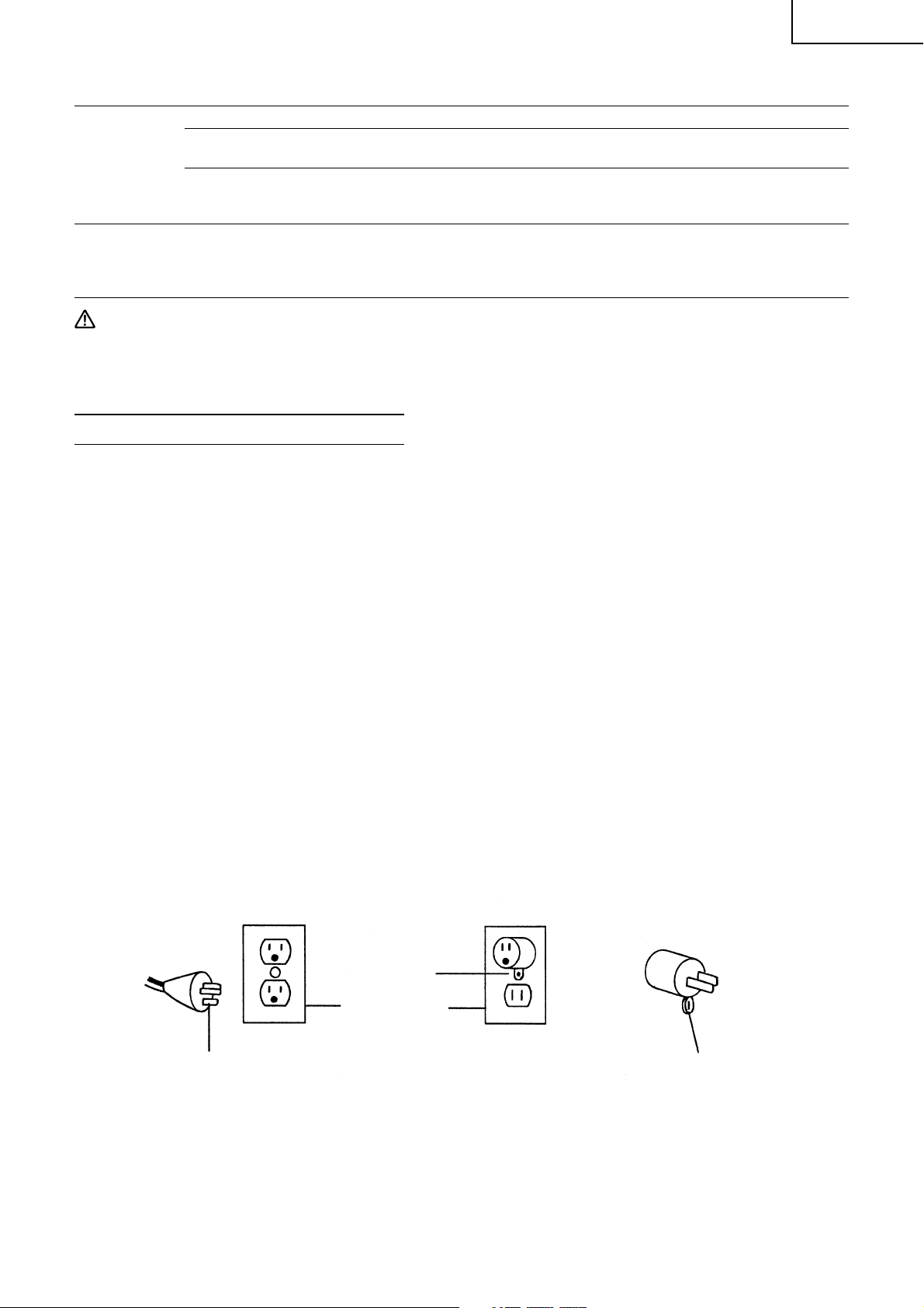
Grounded, cord -connected tools intended for use on a supply circuit having a nominal rating less than 150
volts: This tool is intended for use on a circuit that has an outlet that looks like the one illustrated in Fig. A.
The tool has a grounding plug that looks like the plug illustrated in Fig. A. A temporary adapter, which looks
like the adapter illustrated in Fig. B and C, may be used to connect this plug to a 2-pole receptacle as shown
in Fig. B if a properly grounded outlet is not available. The temporary adapter should be used only until a
properly grounded outlet can be installed by a qualified electrician. The green-colored rigid ear, lug, and the
like, extending from the adapter must be connected to a permanent ground such as a properly grounded
outlet box.
GROUNDING METHODS
Fig. A Fig. B Fig. C
Adapter
Metal Screw
Cover of Grounded
Outlet Box
Grounding Pin
Grounding Means
SAVE THESE INSTRUCTIONS
AND
MAKE THEM AVAILABLE TO
OTHER USERS OF THIS TOOL!
7
Page 8
English
OPERATION AND MAINTENANCE
NOTE: The information contained in this Instruction Manual is designed to assist you in the safe operation
and maintenance of the power tool. Some illustrations in this Instruction Manual may show details
or attachments that differ from those on your own power tool.
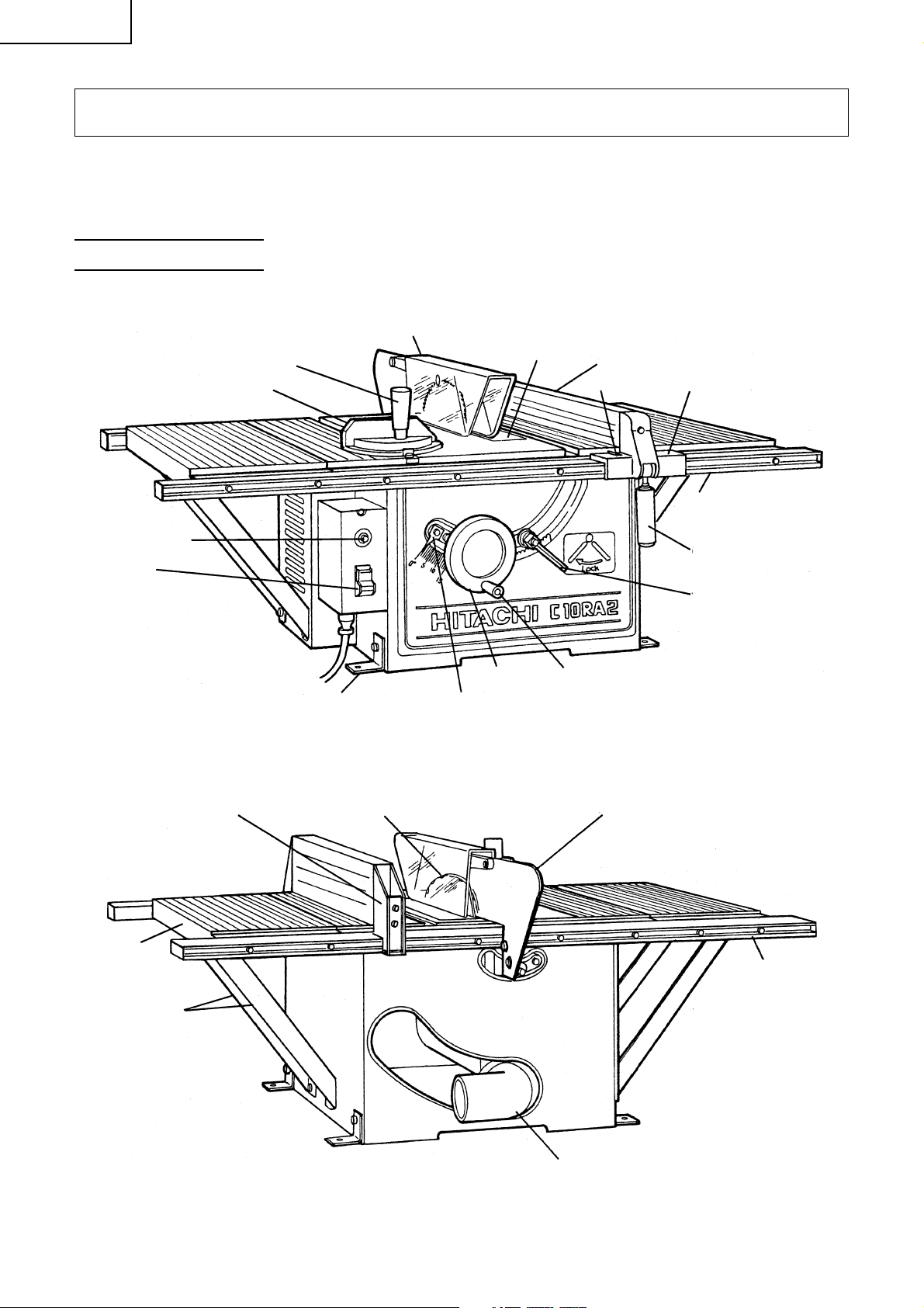
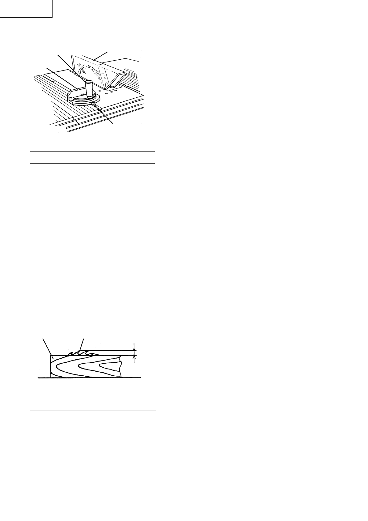
NAME OF PARTS
Saw Blade Guard Assembly
Reset Button
Switch
Clamp Handle (B)
Miter gauge
Set Plate
(Standard Accessory)
Needle Pointer
Fig. 1
Insert Rip Fence
Pointer
Handle BarWheel
Width Body
Front Rail
Grip
Tilt Lock Handle
Extension Wing
Extension Supporter
8
Support
Saw Blade
Fig. 2
Spreader
Elbow
(Standard Accessory)
Rear Rail
Page 9
SPECIFICATIONS
Item Model C10RA2
Type Series commutator motor
Motor
Applicable saw blade Outside Dia. 10" (255 mm)
No load speed 5000 rpm
Max. sawing dimension 90° Max. Height 3"
Net weight 64 lbs. (29 kg)
Cord 3 conductor type cable 6.6 ft. (2 m)
Power source Single-phase AC 60Hz
Voltage (volts) 115
Full-load current (Amp) 15
Hole Dia. 5/8" (15.9 mm)
Bevel 45° Max. Height 2 – 1/2"
English
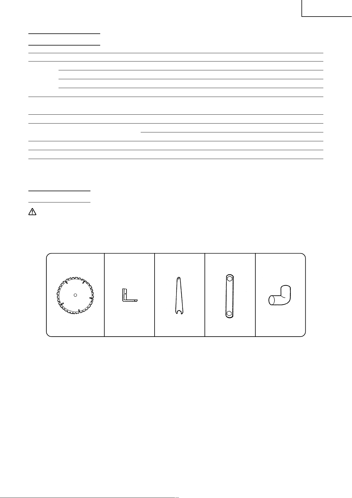
ACCESSORIES
WARNING:Accessories for this power tool are mentioned in this Instruction Manual.
The use of any other attachment or accessory can be dangerous and could cause injury or
mechanical damage.
STANDARD ACCESSORIES
q 10" (255 mm) TCT w Set Plate e Wrench r Hex. Wrench t Elbow
Saw Blade (1 piece) (4 pieces) (1 Piece) (1 Piece) (1 Piece)
For how to use, For how to use,
refer to page. 11 refer to page. 14
Fig. 3
9
Page 10
English
OPTIONAL ACCESSORIES…sold separately
q Dado Insert (For dado cutter set) (Code No.314325) Convenient for dado cutting. Refer to parts list.
w Push Stick (Code No.314324) Convenient for ripping small pieces cutting. Refer to parts list.
e Table Saw Stand (Code No.314819) Convenient for setting the table saw. Refer to Fig. 12-c.
WARNING:Using attachments or accessories not recommended in this manual can be dangerous
and cause personal injury or mechanical damage to the saw.
APPLICATIONS
Wood (hard or soft woods)
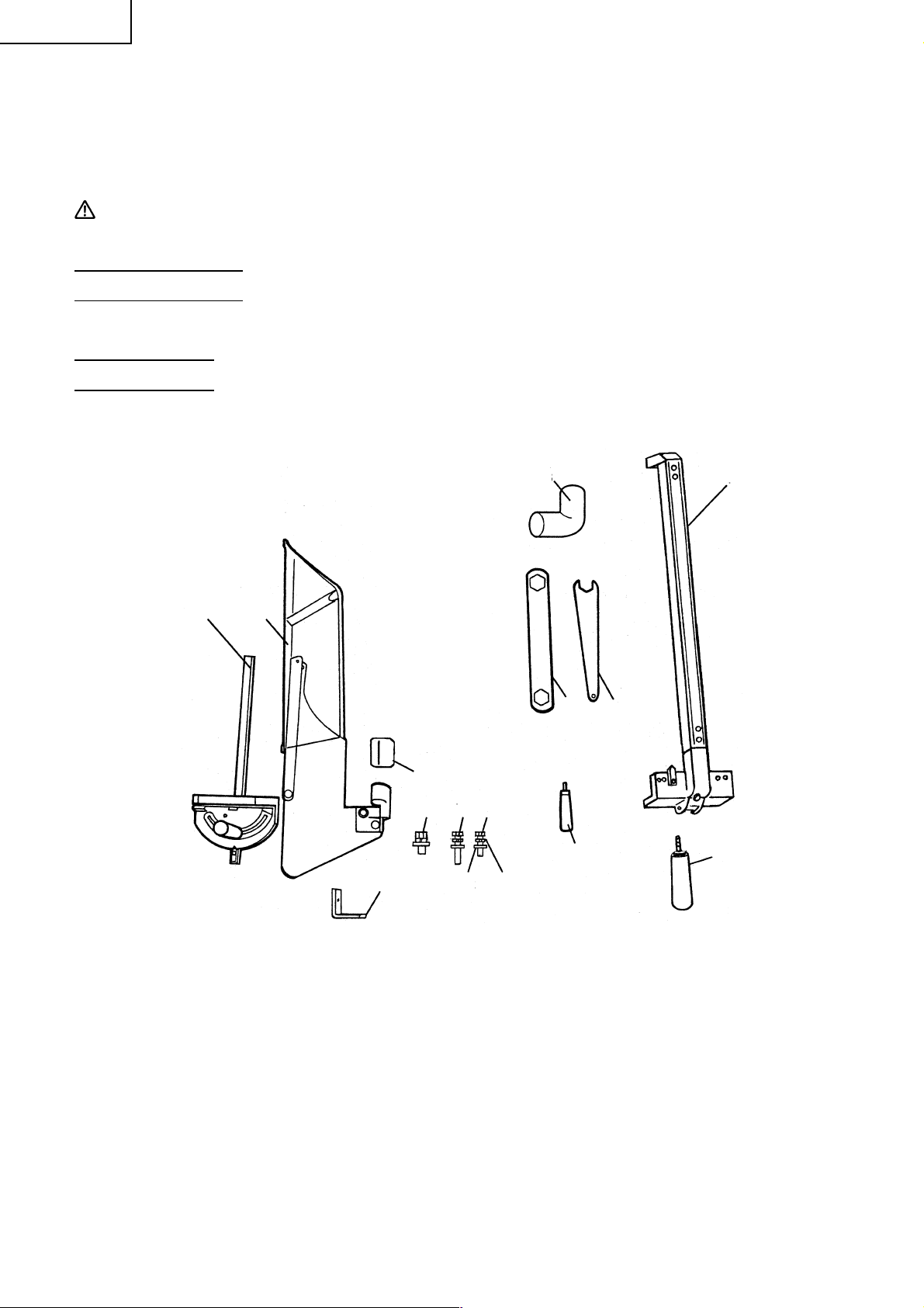
UNPACKING
The parts illustrated in Fig. 4 described are packaged together with the tool. When unpacking, carefully
confirm that all parts are accounted for.
12
14
15
13 10 9
12 11
3
56
7
4
8
Fig. 4
1. Miter Gauge (1 piece) 8. Grip (1 piece)
2. Saw Blade Guard and Spreader Assembly (1 piece) 9. 6 × 90 mm Bolt (1 piece)
3. Elbow (1 piece) 10. 6 × 110 mm Bolt (1 piece)
4. Rip Fence (1 piece) 11. 6 mm Spring Washer (2 pieces)
5. Hex. Wrench (1 piece) 12. 6 mm Flat Washer (2 pieces)
6. Wrench (1 piece) 13. 8 × 20 mm Bolt (with / washers) (4 pieces)
7. Handle Bar (1 piece) 14. Set Plate (4 pieces)
15. Cusion (1 piece)
10
Page 11
English
PREPARATION BEFORE OPERATION
Make the following preparations before operating the power tool:
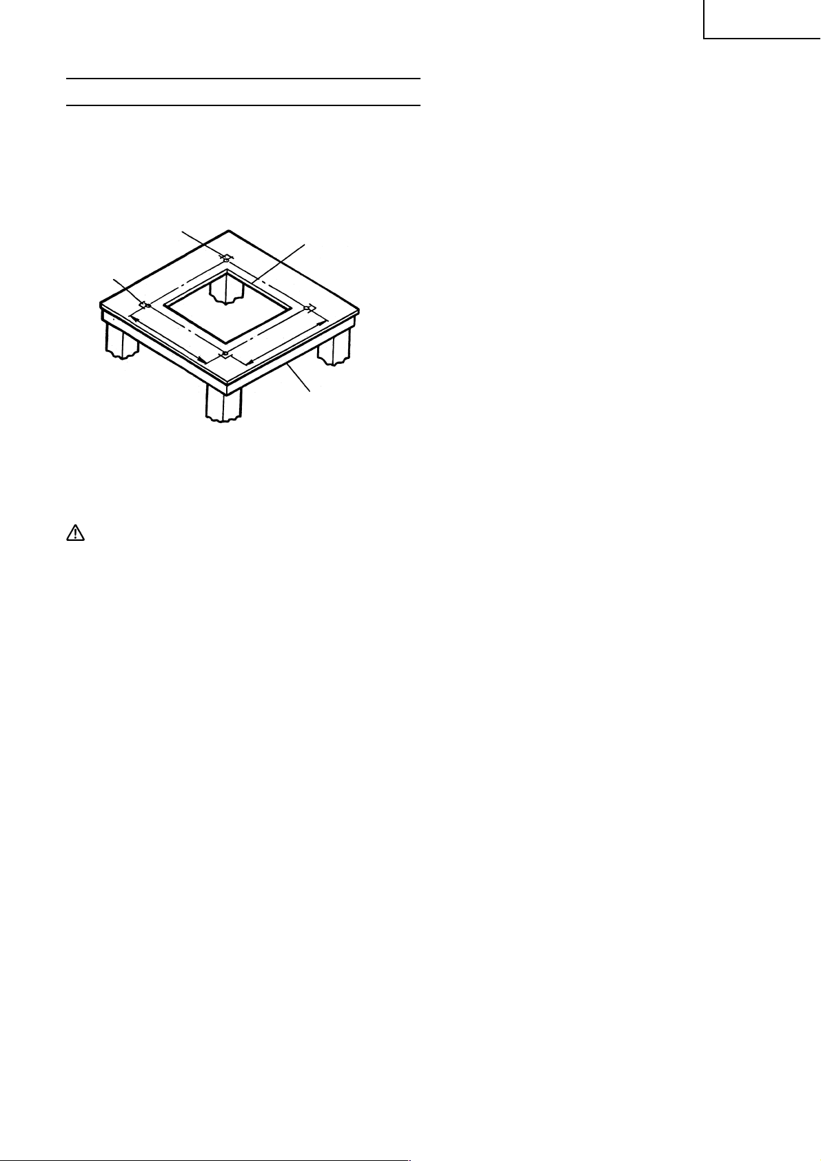
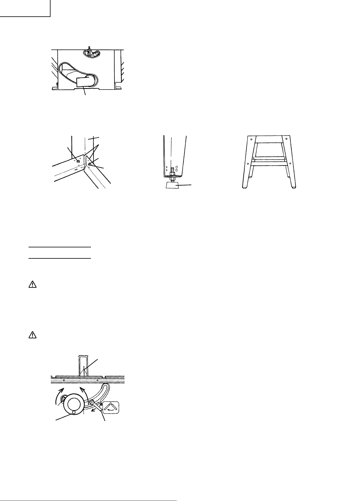
1. Installation
The table saw must be properly secured to a sturdy workbench, stand or cabinet.
Casters (if provided) on the workbench, stand or cabinet must be locked during operation.
If there is any tendency for the table saw to move during operation, this must be corrected immediately.
5/16" (8 mm) Holes
Set Plate
Locating Marks
15-3/4" (400 mm)
Fig. 5
12" (305 mm) Square
Cut Out (center)
17-23/32" (450 mm)
Work Bench, Stand
or cabinet
(3) Remove the table saw, and locate a 11" (279 mm) or 12" (305 mm) square centered between the marks
locating the body shell. Cut out and remove the square. This opening allows sawdust to fall out of the
body shell.
(1) Place the table saw in the desired location.
Make certain that is (or will be) adequate space on all
sides of the table saw for the workpiece.
To allow maximum flexibility for sheet material and
long boards, 9 foot (2745 mm) clearance is
recommended on all sides of the table saw.
(2) Secure the four set plates to the saw base at its four
corners with four 8 × 20 mm bolts (with/washers) and
four 8 mm nuts.
Square the table saw to the workbench, stand or
cabinet. Make certain that all controls are easily
reached and there is at least 6-11/16" (170 mm) behind
the rear of the table to allow for the saw blade guard
assembly.
Temporarily mark the location of the four base corners
and set plate of the table saw.
CAUTION: Failure to provide this opening can result in insufficient cooling air to the motor causing
premature motor failure and a possible fire hazard.
(4) Replace the table saw, aligning it with the marks made above. Trace hole positions on the four set plates
on the workbench, stand or cabinet with a pencil or the like.
(5) Remove the table saw, and drill a 5/16" (8 mm) hole in each location marked. Remove all sawdust or
chips.
(6) Replace the table saw in the marked location. Check to see that the table saw does not lock on the
workbench and all four set plates are in contact with the top of the workbench, stand or cabinet.
(7) Using suitable length four 2" (50 mm) bolts, nuts, and flat washers (not provided) secure the table saw to
the workbench, cabinet or stand. Place a spring washer and flat washer on the bolt, place the bolt through
the hole in the set plate and the top of the workbench stand, or cabinet. Add another flat washer and a
nut. Do not tighten the nut yet. Repeat this operation for the other three locations.
Tighten all nuts securely.
(8) Check the sturdiness of the resulting assembly.
11
Page 12
English
ASSEMBLY PROCEDURES
WARNING:To avoid an accident or personal injury, always confirm that the switch is turned OFF and
the power plug has been disconnected from the receptacle before assembly of this tool.
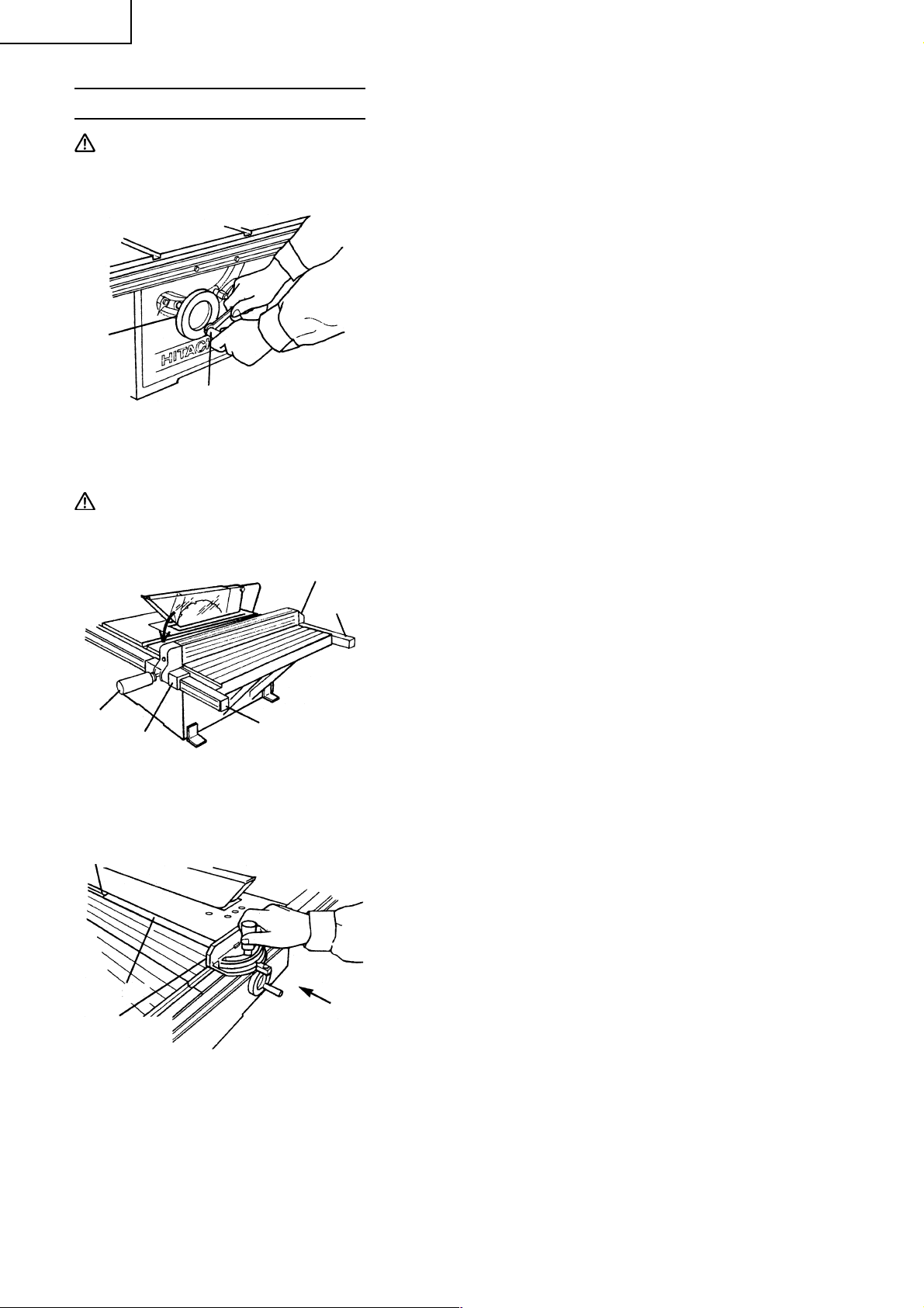
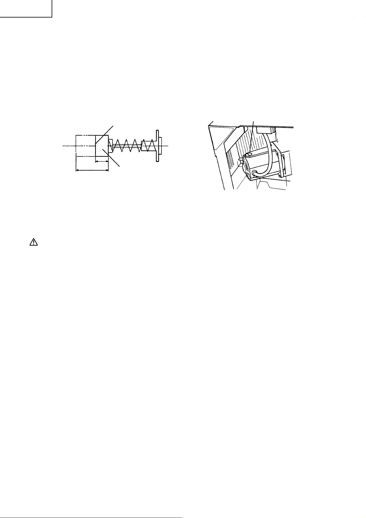
1. Assembly of Handle Bar
Wheel
Handle Bar
Fig. 6
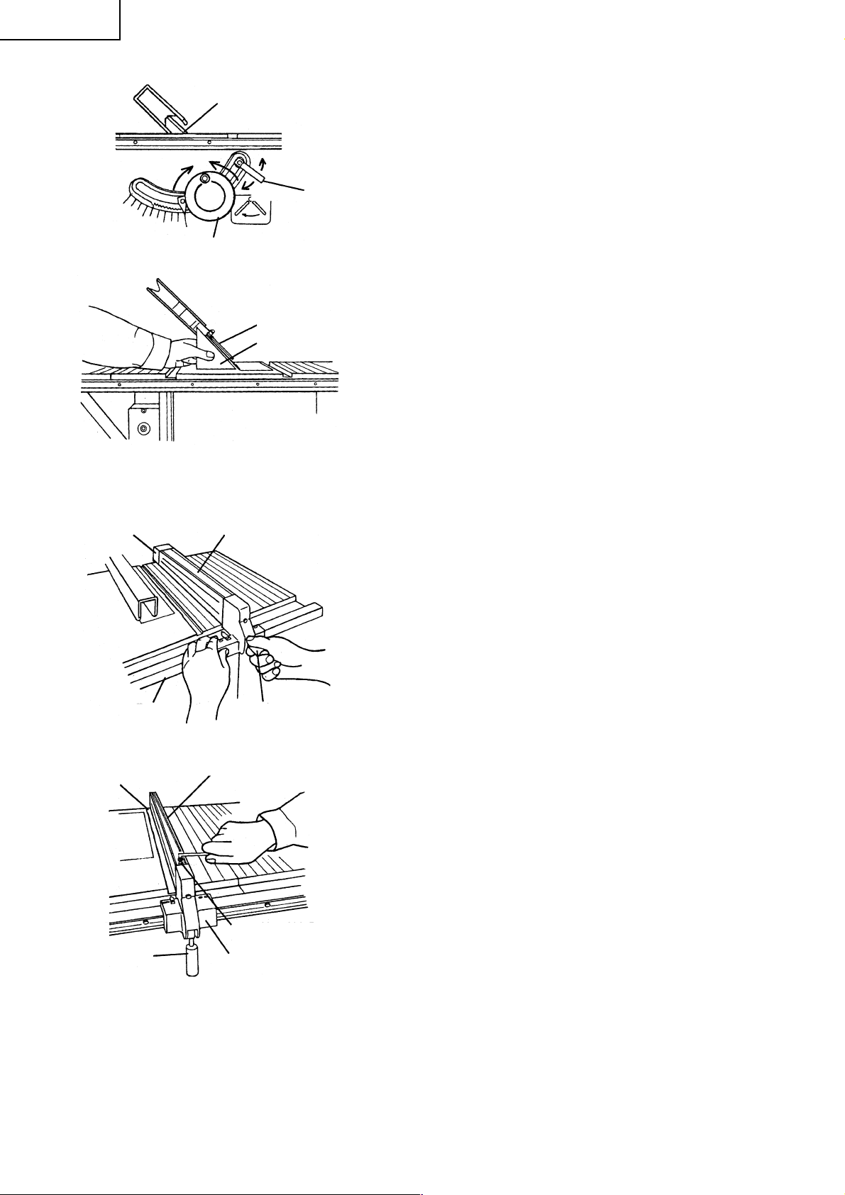
2. Installing of Rip Fence
The handle bar allows faster turning of the wheel.
When properly assembled it with rotate freely but with only a
small amount of play,
(1) Tighten the screw of the handle bar until it hits against the
wheel.
(2) Securely tighten the handle bar nut with a wrench.
CAUTION: The rip fence must be aligned parallel to the saw blade to minimize the kickback (refer to
page 19).
Support
The rip fence can be conveniently used to cut a workpiece into
different pieces of precise width or into parallel pieces. It can be
Rear Rail
mounted on either the right or left side of the table.
(1) Tighten the screw of the grip.
(2) Catch the hook of the support in the bottom part of the rear
rail.
(3) Lower the rip fence in the arrow direction, and fit the part of
Grip
Width Body
Front Rail
Fig. 7
the width body and support to the groove of the front and
rear rail.
(4) Confirm that the rip fence is moved right and left and it moves
smoothly.
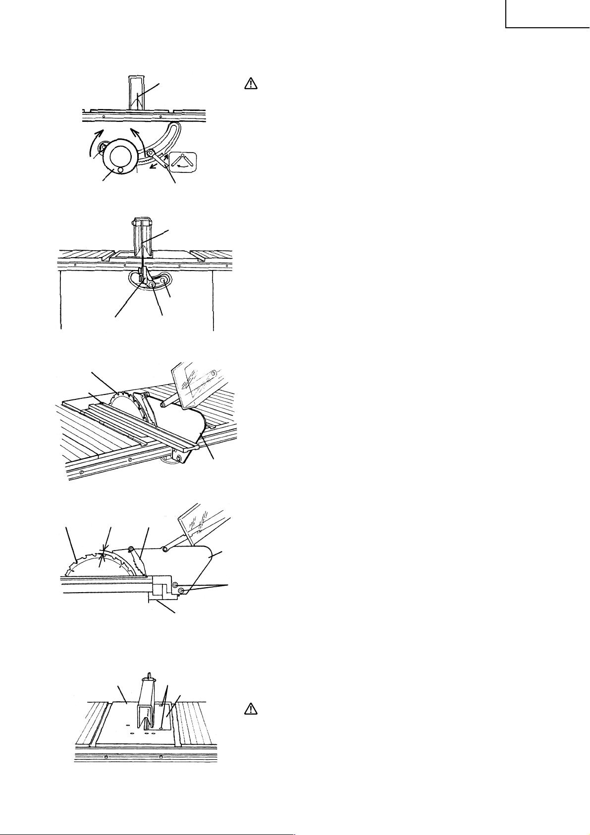
3. Assembly of Miter Gauge
Miter Gauge Groove
The miter gauge is convenient for cutting long or angular pieces
which are difficult to work on with the rip fence. It can be mounted
on either the right or left side of the table. Align the sheet bar of
miter gauge with the miter gauge groove and slide it in the
direction indicated by the arrow through the front of the table.
Sheet Bar
Miter Gauge
12
Fig. 8
Page 13
4. Mounting and adjusting Saw Blade Guard Assembly
English
Up
Wheel
Saw Blade
Straightedge
Down
Tighten
Fig. 9-a
6 × 110 mm BoltGuard Bracket
Fig. 9-b
Fig. 9-c
Saw Blade
Loosen
Tilt Lock Handle
Spreader
6 × 90 mm Bolt
Spreader
CAUTION: The saw blade guard and spreader assembly
must be aligned properly to the saw blade in
order to prevent kickback.
Mount the saw blade guard assembly, which includes the
spreader and anti-kickback pawls (see Fig. 9-d).
(1) Mounting the spreader
q Loosen the saw blade tilt lock handle, move the saw blade
tilting mechanism to the left and set the saw blade to 0° by
means of the stopper. Tighten the saw blade tilt lock handle
to lock it in position.
w Turn the wheel fully clockwise and set the saw blade to
the maximum cutting height (see Fig. 9-a).
e Put a 6 mm spring washer and a D13 flat washer on to the
6 × 90 mm and 6 × 110 mm bolts.
r Tentatively fasten the spreader on the rear section of the
body using the cusion and two 6 mm bolts mentioned
above (see Fig. 9-b and Fig. 9-d).
(The guard bracket must be attached to the spreader in
advance.)
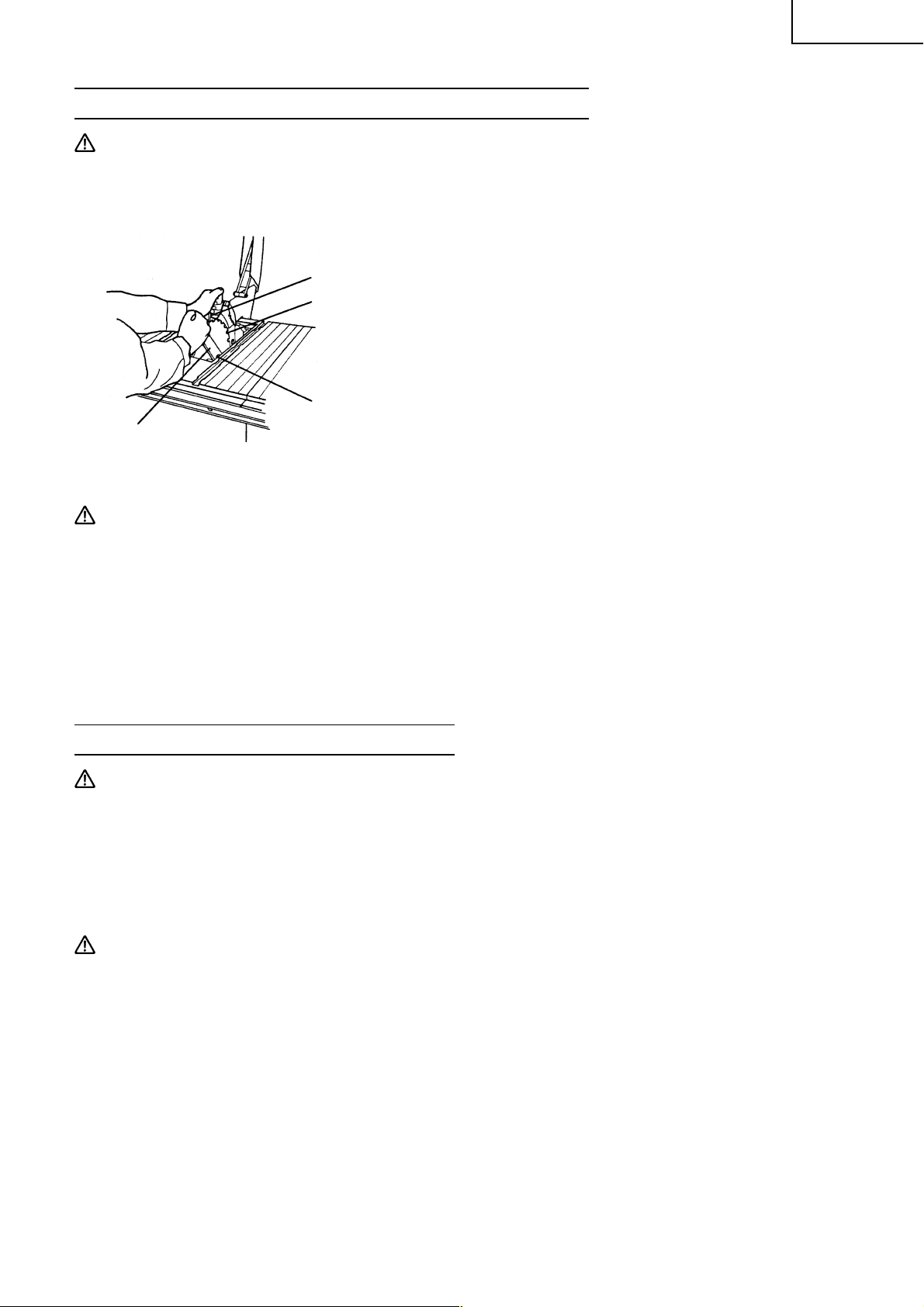
(2) Adjusting the spreader
q Use a straightedge to align the spreader with the saw blade
(see Fig. 9-c).
Tighten the two 6 × 16 mm bolts (see Fig. 9-d) with a wrench
to lock the spreader.
w Check clearance between saw blade tip and spreader.
It should be less than 1/2" (12.7 mm) at all positions. If not,
loosen the two 6 × 16 mm bolts securing the spreader to
the guard bracket with a wrench and move the spreader
up and down. After adjustment of the spreader is complete,
firmly retighten the two 6 × 16 mm bolts with a wrench
(see Fig. 9-d).
Saw
Blade
Less than
1/2"(12.7 mm)
Anti-kickback
pawl
Cusion
Fig. 9-d
5. Mounting Table Insert
Table 5 mm Machine Screw
Fig. 10
Table Insert
Spreader
6 × 16 mm
Bolt
The table insert is mounted to the table with two 5mm machine
screws.
CAUTION: The table insert must be in place and securely
fastened at all times.
13
Page 14
English
6. Mounting Elbow (Chip Extraction Duct) (Standard Accessory)
Connect a 2 – 9/16" (65 mm) hose of dust collector to the chip
extraction duct to suck cutting chips away. Mount the chip
extraction duct on the chip discharge outlet at the body rear of
the body.
Elbow (Chip Extraction Duct)
Fig. 11
7. Assembly of Table Saw Stand (Optional Accessory)
Leg
Washer
Stay
Cap Square Neck Bolt
Nut
Rubber Cap
Fig. 12-a Fig. 12-b Fig. 12-c
Assemble it with the stay and leg(s). Set the stays below and assemble the legs outside (see Fig. 12-c).
Secure with cup square neck bolts and nuts (see Fig. 12-a).
Then attach rubber caps underneath the legs (see Fig. 12-b).
ADJUSTMENT
This tool is accurately adjusted before shipping from the factory.
Check the following accuracies and readjust them if necessary in order to obtain the best results in operation.
WARNING:To avoid an accident or personal injury, always confirm that the switch is turned off and
the power plug has been disconnected from the receptacle before adjustment of this tool.
1. Adjustment of saw blade parallel to miter gauge groove.
This is the most probably difficult of the adjustments. Before shipment from the factory this adjustment
was made but it should be rechecked and readjusted if necessary.
CAUTION: This adjustment must be correct. Kickback could result and accurate cuts cannot be made.
(1) Loosen the saw blade tilt lock handle by turning it
Up
Wheel
Saw Blade
Down
Loosen
Tighten
Tilt Lock Handle
Fig. 13-a
counterclockwise. Move the saw blade tilting mechanism to
the left and set the saw blade to 0° with the stopper.
(2) Turn the wheel fully clockwise and set the saw blade to the
maximum cutting height (see Fig. 13-a).
(3) Select a tooth on the saw blade which is bent to the right.
(4) Mark that tooth with a pencil or permanent marker.
(5) Set the miter gauge to 90° and tighten the clamp handle (B) to
lock it in that position. Place the miter gauge in the left hand
miter gauge groove in the table top (see Fig. 13-b).
14
Page 15

Clamp
Handle (B)
Miter
Gauge
Clamp
Handle (B) Bar
Miter
Gauge
Bar
Fig. 13-b
6 mm Machine
Screw (A)
Fig. 13-c
Saw Blade
Saw Blade
6 mm Flat
Screw
(6) Rotate the saw blade to bring the marked tooth in the front
(7) Place the bar of square flat against the miter gauge.
(8) Move the bar of square toward the saw blade until it just
(9) Without disturbing the bar clamped to the miter gauge, move
(10) Slide the miter gauge rearward until the clamped bar is closest
(11)If the bar just touched the tooth when the gauge was in the
(12)If the front and rear clearance are not identical,
6 mm Machine
Screw (B)
English
and about 1/2" (12.7 mm) above the table top.
touches the tip of the marked saw blade tooth.
the miter gauge to the center of the saw blade.
to the tip of the marked saw blade tooth (see Fig. 13-c).
front position, it should just touch the tooth in the rear position.
Likewise, if there was some clearance between the bar and
the tooth tip at the front, the same clearance should be at the
rear.
q Remove the miter gauge.
w Loosen four 6mm flat screws.
e Move the body and adjust it so that a bar placed on the
miter gauge is as wide as the clearance between the front
and rear of the saw blade.
r Tighten the four 6mm flat screws.
2. Adjusting 90° and 45° positive stops
This tool is equipped with positive stops for rapid and accurate
positioning of the saw blade at 90° and left bevel 45° to the table.
Check and adjust the positive stops by the following procedures.
(1) To adjust positive stop at 90°.
(2) To adjust positive stop at left bevel 45°.
Up
Wheel
Square
Saw Blade
Down
Loosen
Tighten
Tilt Lock Handle
Fig. 14-a
Saw Blade
Fig. 14-b
Needle Pointer
5 mm Machine Screw
Fig. 14-c
q Turn the wheel fully clockwise and set the saw blade to
the maximum cutting height.
w Loosen the saw blade tilt lock handle and move the saw
blade tilting mechanism to the left until it hits against the
stopper.
Then tighten the saw blade tilt lock handle (see Fig. 14-a).
e Use a square to check the saw blade is at a precise 90°
(see Fig. 14-b).
r If the saw blade is not at a precise 90°, loosen the saw
blade tilt lock handle by turning it counterclockwise. Loosen
the 6mm machine screw (A) (see Fig. 13-c) a few turns and
move the saw blade tilting mechanism until the blade is at
90° to the table (see Fig. 14-b).
t Tighten the saw blade tilt lock handle after adjustment.
y Loosen the 5mm machine screw and set the needle pointer
to 0°. On completion of adjustment, recheck the 90° of the
saw blade and table (see Fig. 14-c).
q Turn the wheel fully clockwise and set the saw blade to
the maximum cutting height.
w Loosen the saw blade tilt lock handle and move the saw
blade tilting mechanism to the right until it hits against
the stopper.
Then tighten the saw blade tilt lock handle (see Fig. 15-a).
e Use a 45° gauge to check the saw blade is at a left bevel
45° (see Fig. 15-b).
15
Page 16
English
Saw Blade
Down
Up
Tighten
Wheel
Fig. 15-a
Saw Blade
45° Gauge
Fig. 15-b
3. Adjustment of rip fence
Loosen
Tilt Lock
Handle
r If the saw blade is not at a left bevel 45°, loosen the saw
blade tilt lock handle. Loosen the 6mm machine screw (B)
(see Fig. 13-c) a few turns and move the saw blade tilting
mechanism until the blade is at left bevel 45° to the table
(see Fig. 15-b).
t After adjustment, tighten the saw blade tilt lock handle.
y On completion of adjustment, recheck the left 45° bevel of
the saw blade and table.
Support
Miter Gauge
Groove
Grip
Fig. 16-a
Parallel Bracket
Fig. 16-b
Rip Fence
GripFront Rail
6 mm Hex. Hd. Bolt
Width Body
Before shipment from the factory the saw blade is set parallel to
the miter gauge groove and the rip fence is adjusted parallel to
the miter gauge groove. Check and adjust the parallel of the rip
fence by the following procedures. In order to accurate work and
prevent kickback when ripping. Before adjustment of rip fence,
check and adjust slider (It is assembled under the width body.) to
engage with the groove on front rail.
(1) Raise the grip to the upside and release the fixation of the rip
fence (see Fig. 16-a).
(2) Position the rip fence at one edge of the miter gauge groove.
(3) Lower the grip to the bottom and fix the rip fence. The edge
of the rip fence should line up parallel with the miter gauge
groove.
(4) If the edge of the rip fence is not parallel with the miter gauge
groove.
q Loosen the four 6 mm hex. hd. bolts securing the parallel
bracket to the width body and support.
w Raise the grip to the upside and release the fixation of the
rip fence.
Align the rip fence parallel to the miter gauge groove.
Lower the grip to the bottom and fix the rip fence.
e While holding the parallel bracket to prevent movement,
tighten the four 6 mm hex. hd. bolts previously loosened
(see Fig. 16-b).
r Raise the grip to the upside and release the fixation of the
rip fence. Move and return the parallel bracket adjacent to
the miter gauge groove. Lower the grip to the bottom and
fix the rip fence. And verify that the parallel bracket is
parallel to the miter gauge groove.
t Repeat adjustment until it is parallel.
y After adjustment, tighten four 6 mm hex. hd. bolts.
u On completion of adjustment, recheck the rip fence is
parallel with the miter gauge groove.
16
Page 17
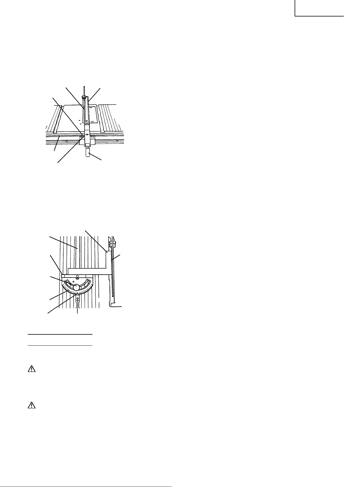
4. Adjustment of pointer
The pointer is equipped to indicate the distance the rip fence is positioned away from the saw blade.
The pointer should indicate the accurate distance from the saw blade.
Check and adjust the pointer by the following procedures.
NOTE: The pointer will need to be readjusted whenever a different thickness saw blade is installed.
English
Saw Blade
Pointer
Rip Fence
To adjust pointer 0 setting.
(1) Raise the grip to the upside and release the fixation of the rip
fence. And move the rip fence to bring it into tight contact
with the side of the saw blade.
(2) Make sure that the pointer points to 0 on the scale provided
on the table.
(3) If the pointer does not point to 0 on the scale,
q Lower the grip to the bottom and fix the rip fence.
Scale
5 mm
Machine Screw
Grip
Fig. 17
w Loosen the 5 mm machine screw holding the pointer (see
Fig. 17).
e Adjust the pointer to the 0 position and retighten the 5
mm machine screw.
r After adjustment, recheck to see that the pointer now points
to 0.
5. Adjustment of Miter Gauge
The miter gauge should be squareness to the saw blade.
Check and adjust the miter gauge the following procedures.
To adjust pointer 0 setting.
(1) Loosen the clamp handle (B) and place a square against both
the saw blade and miter gauge. The pointer should indicate
90° on the protracter scale on the miter gauge.
(2) If the pointer does not point to 0 on the miter gauge,
q Tighten clamp handle (B).
w Loosen the 5 mm machine screw on the sheet bar.
e Adjust the pointer to the 90° position and tighten the
5 mm machine screw on the sheet bar (see Fig. 18).
r After adjustment, recheck to see that the pointer now points
to 0.
Sheet Bar
Miter Gauge
Clamp
Handle (B)
Protractor
Scale
Pointer
Square
Saw Blade
5 mm Machine Screw
Fig. 18
BEFORE USING
1. Make sure the switch is turned OFF.
WARNING:If the power cord is connected to the power source with the switch turned ON the power
tool will start suddenly and can cause a serious accident.
2. Make sure the power source is appropriate for the tool.
WARNING:Never connect the power tool unless the available AC power source is of the same voltage
as that specified on the nameplate of the tool. Never connect this power tool to a DC
power source.
3. Check the saw blade for visible defects.
Confirm that the saw blade is free of cracks or other visible damage.
17
Page 18
English
4. Confirm that the saw blade is attached securely to the power tool.
Using the supplied wrench, tighten the set nut on the saw blade spindle to secure the saw blade.
For details, see Fig. 34 in the section on “SAW BLADE MOUNTING AND DISMOUNTING”.
5. Check the saw blade guard for proper operation.
Saw blade guard is designed to protect the operator from coming into contact with the saw blade during
operation of the tool.
Always check that the saw blade guard moves smoothly.
WARNING:Never operate the power tool if the saw blade guard does not function smoothly.
6. Check the Power Receptacle
To prevent overheating, accidental stopping or intermittent operation, confirm that the power cord plug
fits properly in the electrical receptacle and does not fall out after it is inserted. Repair or replace the
receptacle if it is faulty.
7. Confirm the tool’s power cord is not damaged
Repair or replace the power cord if an inspection indicates that it is damaged.
AFTER CONNECTING THE POWER PLUG TO AN APPROPRIATE AC POWER SOURCE, CHECK THE
OPERATION OF THE TOOL AS FOLLOWS:
8. Trial Run
After confirming that no one is standing behind, the power tool start and confirm that no operating
abnormalities exist before attempting a cutting operation.
9. Inspect the rotating stability of the saw blade
For precise cutting, rotate the saw blade and check for deflection to confirm that the blade is not noticeably
unstable; otherwise vibrations might occur and cause an accident.
PRACTICAL APPLICATIONS
1. Switch operation
To turn the table saw on, raise the red portion of the switch. To
Reset
Button
Switch
Fig. 19
turn the table saw off, push the red portion of the switch. Try this
operation without the saw being plugged in.
WARNING:Always remove the safety key from the switch
when the table saw is not in use. This will ensure
that the table saw cannot be turned on
accidentally or by someone (especially a child)
who is not qualified to use the table saw.
If the safety key is left in the switch, serious
personal injury can result.
2. Overload protective device for motor
When the motor becomes overload, the overload protective device cuts off the current to stop the motor.
In this case, push the reset button (after few minute later).
18
Page 19

3. Raising and lowering saw blade
(1) Raising saw blade.
Saw Blade
Grasp the wheel and rotate it clockwise to raise the saw blade.
(2) Lowering saw blade.
Grasp the wheel and rotate it counterclockwise to lower the
saw blade.
CAUTION: Adjust the saw blade height so it is about 1/8"
Up
Down
Loosen
(3.2 mm) above the top of the workpiece.
Tighten
Tilt Lock HandleWheel
Fig. 20
Raising the saw blade much higher than the
workpiece does not make it cut better. It is
unsafe and provides less table surface in front
of the saw blade.
Never operate while saw blade rotating.
4. Saw Blade Tilting Operation
The saw blade tilt lock handle is spring loaded and can be repositioned by pulling out on the handle and
repositioning it on the serrated stud located underneath the handle.
WARNING:The saw tilt lock handle must be locked during
all cutting operations.
English
Saw Blade
Down
Up
Wheel
Fig. 21
5. Rip Fence Operation
Rip Fence
Loosen
Tighten
Tilt Lock
Handle
Two methods are available tilting saw blade and are as follows.
(1) Rapid saw blade tilting.
Loosen saw blade tilt lock handle, move the wheel until the
saw blade is at the desired angle and tighten saw blade tilt
lock handle.
(2) Fine adjustment saw blade tilting.
q Loosen saw blade tilt lock handle.
w Push in wheel until teeth on hub of hand wheel engauge
with segment gear.
e Turn wheel to tilt the saw blade to the desired angle and
tighten saw blade tilt lock handle.
The rip fence can be used on either side of the saw blade.
The pointer on rip fence indicates the distance between the saw
blade and rip fence.
(1) Raise the grip to the upside and release the fixation of the rip
fence.
(2) Move the rip fence right and left while pressing the width body
against the table surface and set the desired distance from
the saw blade.
(3) Lower the grip to the bottom and fix the rip fence.
Fig. 22
Grip
Width Body
WARNING:The grip must be locked during all cutting
operations.
Confirm the rip fence has been properly locked
before operation.
To prevent personal injury, never operate the
power tool if the rip fence is loose.
CAUTION: Make sure that the rip fence is always in parallel
with the miter gauge groove on the table.
19
Page 20
English
6. Miter Gauge Operation
Clamp
Handle (B)
Miter Gauge
Fig. 23
Blade Guard
Miter Gauge
Groove
The miter gauge can be used on either side of the miter gauge
grooves on the table. However, for bevel cutting (the saw blade
is tilted), use the miter gauge in the right side miter gauge groove
to prevent hands or miter gauge from interfering with the saw
blade guard. Miter gauge is accurately adjustable at 90° and 45°
right and left in relation to the saw blade.
Intentional miter cut angle can be otbained easily.
(1) Loosen clamp handle (B).
(2) Turning the miter gauge to the desired angle.
(3) Tighten clamp handle (B) to lock the miter gauge.
WARNINGS ON OPERATION
For your own safety carefully read and observe the following warnings and precautions in addition to the
[IMPORTANT INFORMATION], [SAFETY] and [WARNING]
1. The saw blade is firmly locked.
2. Never perform any operation “free hand” without using the miter gauge, rip fence, and or other auxiliary
devices. To do so could cause accidents from kickback should the saw blade become locked in the
workpiece material.
3. When miter gauge is used, remove rip fence from table.
4. When the miter gauge is used, securely tighten clamp handle (B).
5. When rip fence is used, remove miter gauge from table.
6. When the rip fence is used, securely lock the grip.
7. If blade stalls or stops, TURN SWITCH OFF before releasing blade.
8. Never remove small cut-off pieces with your fingers. Remove them by pushing them clear with a long
stick.
9. Never attempt to remove small cut-off pieces trapped inside the saw blade guard while the saw is
running. Turn the switch “OFF”, allow the saw blade to come to a complete stop, raise the saw blade
guard, and remove the cut-offs.
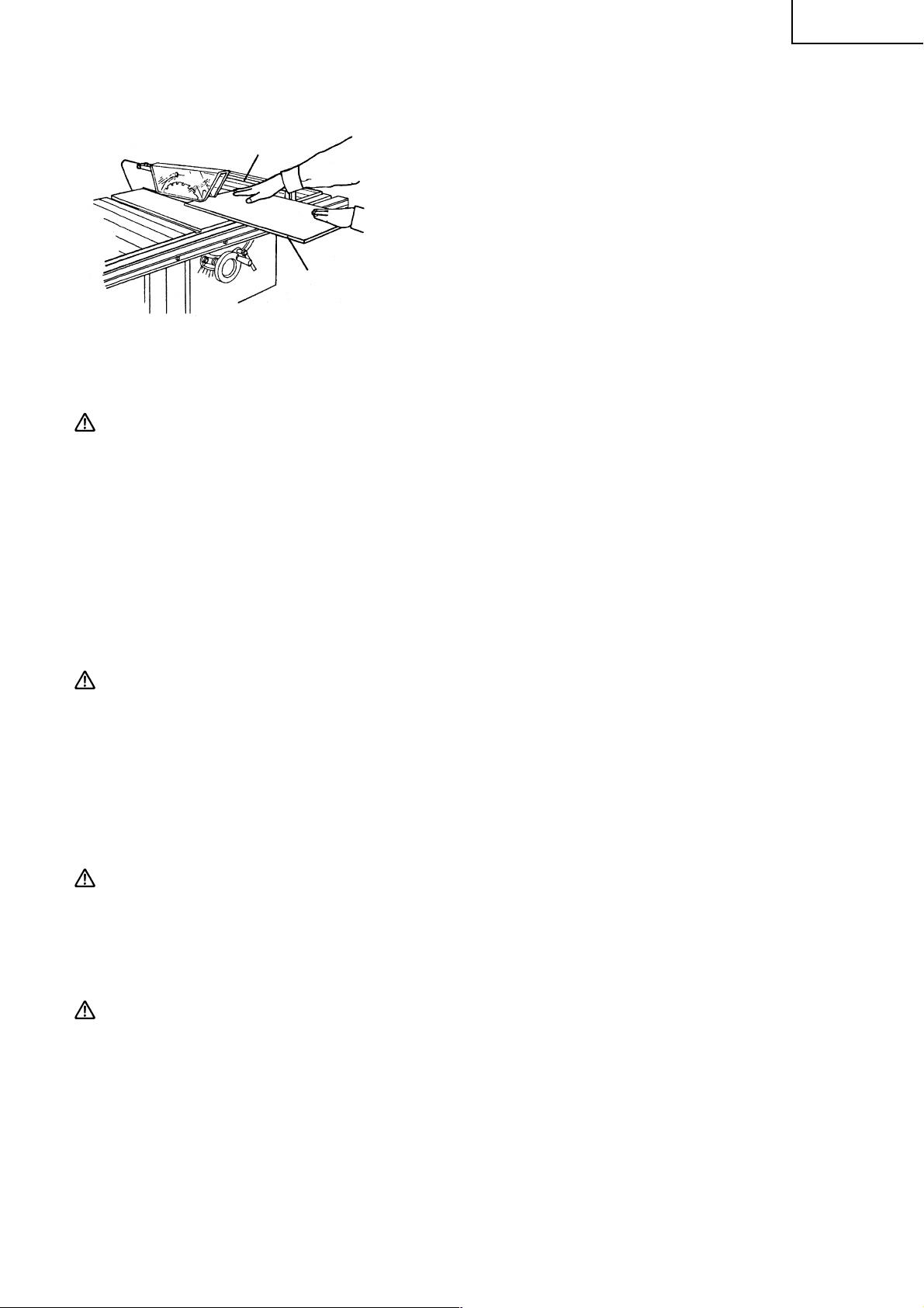
10. Adjust the saw blade height so it is about 1/8" (3.2 mm) above the top of the workpiece. More exposure
would be hazardous (see Fig. 24).
Workpiece
Saw Blade
Approx. 1/8"
(3.2 mm)
11. Never touch any cut-offs while saw blade is running.
12. Feed material slowly in order to make fine cut, keep accuracy,
and avoid overloading.
Fig. 24
OPERATING INSTRUCTIONS
There are two basic types of cuts. Ripping and cross cutting. In general, cutting with the grain is ripping and
across the gain is cross cutting. Neither ripping or cross cutting may be done safely freehand. Ripping
requires the use of the rip fence and cross cutting uses the miter gauge. Safety glasses are being worn.
ALWAYS USE EYE PROTECTION WHEN WORKING WITH THE TOOL TO PREVENT EYE INJURY.
Ordinary eyeglasses do not provide adequate protection since the lenses are not made of safety glass. Also,
use a face mask for additional safety and wear a dust mask if the cutting operation produces dust.
20
Page 21
1. Ripping
Confirm the following items before ripping.
Rip Fence
Workpiece
Fig. 25
(1) Rip fence is parallel to saw blade.
(2) Rip fence is securely fixed.
(3) Remove the miter gauge.
(4) Spreader is properly aligned with saw blade.
(5) Anti-kickback pawls are functioning properly (see Fig. 9-d).
Cutting operation
q Adjust the saw blade height so it is about 1/8" (3.2 mm) above
the top of the workpiece.
w Hold the workpiece flat on the table and against the rip fence.
Keep the workpiece about 1" (25 mm) away from the saw
blade.
CAUTION: The workpiece must have a straightedge against the rip fence and must not be warped,
twisted or bowed. Keep both hands away from the saw blade and away from the path of
the saw blade.
English
e Turn on the switch on and allow the saw blade to come up to speed.
r Keeping the workpiece against the table and rip fence, slowly feed the workpiece rearward all the way
through the saw blade. Continue pushing the workpiece until it is clear of the guard and it falls off the
rear of the table.
t When ripping long boards or large panels, always use an adequate support.
A simple support can be prepared by fixing a piece of plywood to a sawhorse or the like.
y When the width of rip is more than 6" (152 mm) feed the workpiece with one or both hands continusly
until it is beyond the saw blade and anti-kickback pawls.
CAUTION: Do not push the free piece that is cut off, merely guide it.
u When the width of rip 2" (50 mm) to 6" (152 mm) wide, use a push stick to feed the workpiece. (Push stick
is optional accessory)
i When the width of rip is less than 2" (50 mm) wide, use an auxiliary guide a push block.
o When ripping thin material (such as veneer), the workpiece may slide or bind between the bottom of rip
fence and the table surface resulting in impossible ripping. Make a board which has the same height and
length of the rip fence surface by using a piece of 3/4" (19 mm) thick plywood. Fix the board to the rip
fence using four wood screws, so that the bottom of the board touches the table surface.
WARNING:Never operate to pull the workpiece back with the saw blade turning. Turn the switch off,
allow the saw blade to complete stop, raise the anti-kickback pawls (see Fig. 9-d) on each
side of the spreader if necessary and slide the workpiece out.
2. Bevel Ripping
This operation is the same as ripping except that the bevel angle is set to an angle other than 0°.
WARNING:Only work with the workpiece and rip fence on the right side of the saw blade.
21
Page 22

English
3. Ripping small pieces
WARNING:It is unsafe to rip small pieces. It is unsafe to put your hands close to the saw blade.
Workpiece Push Stick
4. Cross Cutting
When a small width is to be ripped and the hand cannot be safely
put between the saw blade and rip fence, use one or more push
sticks. Use them to hold the workpiece against the table and rip
fence and push the workpiece fully past the saw blade.
Rip Fence
Fig. 26
Miter Gauge
(1) Remove the rip fence.
(2) Spreader is properly aligned with saw blade.
(3) Anti-kickback pawls are functioning properly (see Fig. 9-d).
Cutting Operation
q Adjust the saw blade height so it is about 1/8" (3.2 mm) above
the top of the workpiece.
Confirm the following items before cross cutting.
Workpiece
Fig. 27
w Hold the workpiece firmly against the miter gauge with the
path of the saw blade in line with the desired cut distance.
Keep the workpiece about 1"(25 mm) away from the saw blade.
CAUTION: Keep both hands away from the saw blade and away from the path of the saw blade.
e Turn the switch on and allow the saw blade to come up to speed.
r While keeping the workpiece against the face of the miter gauge, and holding the workpiece flat against
the table, slowly push the workpiece through the saw blade.
CAUTION: Never operate to pull the workpiece back with the saw blade turning. Turn the switch off,
allow the saw blade to complete stop, raise the anti-kickback pawls on each side of the
spreader if necessary and slide the workpiece out.
5. Bevel Ripping
Cross Cutting
This operation is the same as cross cutting except that the bevel angle is set to an angle other than 0°.
WARNING:Only operate with the workpiece and miter gauge on the right side of the table.
6. Mitering
Miter Gauge
This operation is the same as cross cutting expect that the miter
gauge is locked at an angle other than 90°.
WARNING:Hold the workpiece firmly against the miter
gauge and feed the workpiece slowly into the
saw blade to prevent the workpiece from
moving.
Workpiece
Fig. 28
22
Page 23
7. Compound Mitering
This is compound of bevel cross cutting and mitering. It is infrequently used. Follow the instruction for
both bevel cross cutting and mitering.
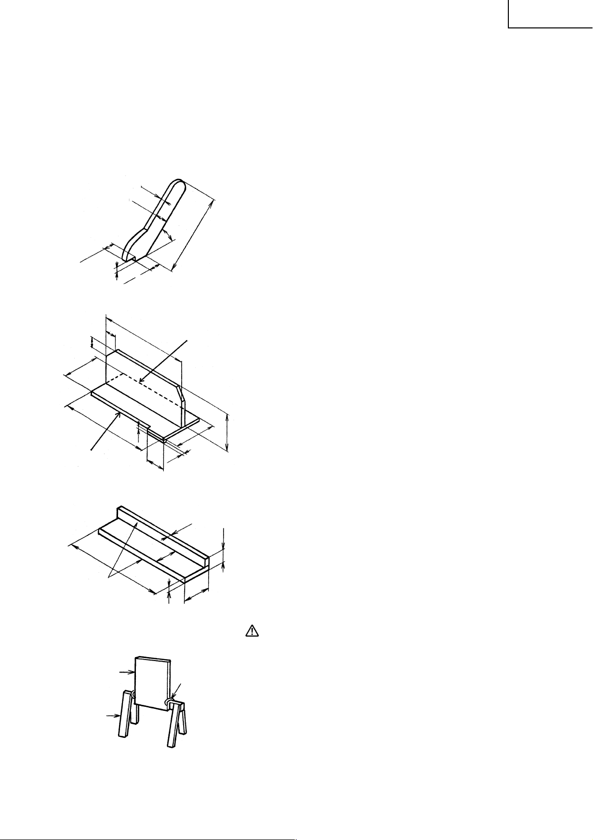
8. Work Helpers
For certain operations, work helpers such as a push stick, push block, auxiliary fence, work support or
the like should be used.
These helpers can be made by yourself using this table saw.
Refer to following figures which shows typical work helpers dimensions.
English
4-3/4"
1-1/4"
A
1"
12"
1/2"
1-1/4"
1"
3/4"
1-1/4"
3/8"
Fig. 29
12"
2-1/2"
45°
3/8"
5-1/8"
12"
B
(1) Push Stick
When the width of rip 2" (50 mm) to 6" (152 mm) wide, use a
push stick to feed the workpiece.
A push stick is available as an optional accessory (refer to
page 10). A push stick can be easily made from a piece of 3/4"
(19 mm) thick plywood.
(2) Push Block
When the width of rip is less than 2" (50 mm) wide, use a
push block.
q Use a piece of 3/8" (9.5 mm) and 3/4" (19 mm) thick
w Glue the small piece of wood 3/8" (9.5 mm) × 3/8" (19 mm)
e Provide a grip in the center of the plywood and fix together
5"
r A and B edges must be parallel.
plywood.
× 2-1/2" (63.5 mm).
with glue and wood screws.
This face and this
edge must be
parallel.
Plywood
Saw Horse
Fig. 30
20"
Fig. 31
Fig. 32
4-3/4"
3/4"
3/4"
“C” clamp
5-1/2"
(3) Auxiliary Fence
2"
When the width of rip is less than 2" (50 mm) the push stick
cannot be used because the saw blade guard (see Fig. 23) will
interfer with a push stick, use an auxiliary fence and push
stick.
q Use a piece of 3/8" (9.5 mm) and 3/4" (19 mm) thick
w Fasten both together with glue and wood screws.
CAUTION: The push block is used with the auxiliary fence.
(4) Work Support
q Clamp a piece of plywood to a sawhorse with “C” clamps.
w Adjust the height of the plywood to level it with the height
plywood.
The 4-3/4" (121 mm) dimension must be the
same on both.
of the table surface.
23
Page 24
English
9. Dado Cutting
WARNING:To prevent an accident or personal injury, always turn off the switch and disconnect the
power plug from the receptacle before mounting or dismounting the dado blade set.
Never attempt to stack dado blades thicker than 1/2" (12.7 mm) thick. Never use the dado set for cut-offs.
Never attempt bevel cuts when dadoing. Never use dado if there is vibration (flutter) or a strange noise.
Never attempt dado in other than wood. Never put hands over the dado blade.
Take every precaution to prevent kickback of the workpiece. Feed workpiece slowly, especially when cutting
deep or wide grooves. When the dado head is hidden from view while cutting, your hands should never be
on top of the workpiece. When using a dado blade, the saw blade guard assembly must be removed since
there is not cut completely through the wood which will allow the spreader to pass through the workpiece.
CAUTION: Use extreme caution when dado cutting.
Always stop the tool and wait for dado blade to come to a complete stop. Then simply
withdraw the wood. Use a push stick. Use rip fence or miter gauge. Be alert for potential
kickback conditions. Follow the dado blade set manufactures recommendations. When
using a dado blade set, the depth of cut is not indicated by the pointer. To know the depth
cut, you must measure it with a ruler. Be sure to place the saw blade guard assembly back
in its original position and check adjustments when the dado cuts are completed.
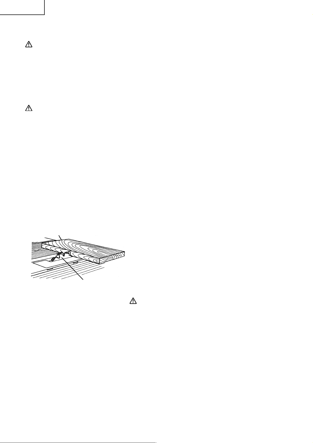
A groove cut into the workpiece is called dado. This dado does not extend completely through the workpiece.
The dado can be made in various widths and depths according to the need. A typical use for a dado is to
make the groove for a shelf. A saw blade can be used to make a dado of any width by marking multiple cuts
side by side. However, it is much easier to use a dado blade. The first has to small blades and a series of
chips to the remove scrap between the blades. The second type consists of a small thick blade which is
caused to wobble by its mounting hubs. This saw will accept dado blades of the cutter chip type to 6" (152
mm) in diameter and 1/2" (12.7 mm) in which. Most wobble type blades are too wide fit on the saw blade
spindle safely. A dado blade requires a table insert which has wider opening. This dado insert is available as
an optional accessory (refer to page 10). Purchase the dado blade set separately.
Mounting the dado blade set
Workpiece
Dado Cutter
Fig. 33
Mounting the dado blade set (see Fig. 33), procedures as follows:
q Remove the saw blade guard assembly with the spreader.
w Remove the table insert.
e Dismount the saw blade.
r Mount the dado blade with the teeth pointing down at the
front of the table (Using the instructions with the dado
blade set).
t Mount the dado table insert (optional accessory), instead
of the table insert.
CAUTION: While tightening the set nut (see Fig. 34), be
careful to maintain the even spacing between
the tips of the inside cutters. Rotate the dado
blade one turn by hand to make sure that it does
not contact anything before operation.
24
Page 25
SAW BLADE MOUNTING AND DISMOUNTING
WARNING:To prevent an accident or personal injury, always turn off the switch and disconnect the
power plug from the receptacle before mounting or dismounting a saw blade.
1. Mounting the saw blade
(1) Turn the wheel (see Fig. 1) fully clockwise and set the saw
blade to the maximum cutting height (see Fig. 14-a).
Wrench
Saw Blade
Set Nut
Hex. Wrench
Fig. 34
(2) Tighten the saw blade tilt lock handle and lock the saw blade
at 90°.
(3) Remove the table insert on the table.
(4) Mount the washer (A), saw blade and washer (A) in this order
on the saw blade spindle. (The saw blade with the teeth
pointing down at the front of the table.)
(5) Using the open end wrench and place the wrench on the flats
on the saw blade spindle. Hold the saw blade spindle from
turning and tighten nut using the remaining hex. wrench by
turning the set nut clockwise.
(6) Replace the table insert on the table.
English
WARNING:Be sure to grip set nut carefully with the hex. wrench. A serious injury can be sustained, if
your grip should slip, the hex. wrench come off the nut, and your hand strike the sharp
blade edges.
When mounting the saw blade, confirm that the rotation indicator mark on the sawblade
and the rotation direction of the saw are properly matched.
Tighten the set nut so it does not come loose during operation. Confirm the set nut (see
Fig. 34) has been properly tightened before the power tool is started.
2. Dismounting the saw blade
Dismount the saw blade by reversing the mounting procedures described in paragraph 1 above.
MAINTENANCE AND INSPECTION
WARNING:To avoid an accident or personal injury, always confirm that the switch is turned OFF and
that the power plug has been disconnected from the receptacle before performing any
maintenance or inspection of this tool.
1. Inspecting the saw blade
Always replace the saw blade immediately upon the first sign of deterioration or damage.
A damaged saw blade can cause personal injury and a worn saw blade can cause ineffective operation
and possible overload to the motor.
CAUTION: Never use a dull saw blade. When a saw blade is dull, its resistance to the hand pressure
applied by the tool handle tends to increase, making it unsafe to operate the power tool.
25
Page 26
English
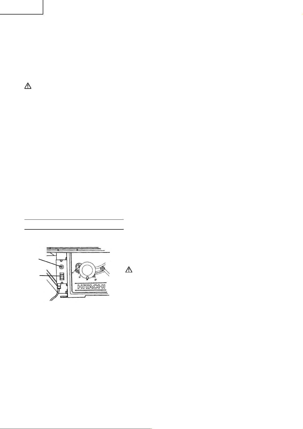
2. Inspecting the carbon brushes (Fig. 35 and Fig. 36)
The carbon brushes in the motor are expendable parts. If the carbon brushes become excessively worn,
motor trouble might occur. Therefore, inspect the carbon brushes periodically and replace them. Check
the carbon brushes after the first 50 hours of use for a new machine or after a new set of carbon brush
have been installed. After the first check, examine them after each about 10 hours of use until such time
that replacement is necessary.
When the carbon on either brush is worn to 3/16" (5 mm) in length or if either spring or shunt wire is
burned or damaged in any way, replace both carbon brushes (see Fig. 35). If the carbon brushes are
found serviceable after removing, reinstall them in the same position as before removed. Also, keep the
carbon brushes clean so that they will slide smoothly within the brush holders. The carbon brushes can
easily be removed after removal of the brush caps (see Fig. 36) with a slotted (minus) screwdriver.
Brush Cap
Motor
Fig. 36
44
3/16"(5 mm)
43/64"(17 mm)
Wear Limit Line
No.44 indicates the last two
numbers of carbon brush code No.
Fig. 35
3. Inspecting the mounting screws
Regularly inspect each component of the power tool for looseness.
Re-tighten mounting screws on any loose part.
WARNING:To prevent personal injury, never operate the power tool if any components are loose.
4. Inspecting the saw blade guard for proper operation.
Before each use of the tool, test the saw blade guard (see Fig. 1) to assure that they are in good condition
and that they move smoothly. Never use the tool unless the saw blade guard operates properly and
unless they are in good mechanical condition. Ensure the anti-kickback pawls are always sharp so they
dig into the workpiece to help prevent kickbacks. If any damage has occurred, repair it promptly.
5. Frequently clean the saw blade guard.
Wipe off saw dust attached to the inside of the see-through saw blade guard using a soft cloth. Do not
use solvent (gasoline, thinner etc.), solvents will damage plastic parts.
6. Storage
Confirm that the switch is turned OFF, that the power plug has been removed from the receptacle and
that the safety key has been removed and has been in a secure place, after operation of the tool has been
completed. When the tool is not in use, keep it stored in a dry place out of the reach of children.
7. Lubrication
Lubricate the following moving parts and rotating parts once a month to keep the power tool in good
operating condition for a long time (see Fig. 1 and Fig. 2). Use of machine oil is recommended.
Oil supply points:
Rotary and moving portion of wheel
8. Cleaning
Periodically remove chips and other waste material from the surface of the power tool with a damp,
soapy cloth. To avoid a malfunction of the motor, protect it from contact with oil or water.
26
Page 27

English
SERVICE AND REPAIRS
All quality power tools will eventually require servicing or replacement of parts because of wear from
normal use. To assure that only authorized replacement parts will be used, all service (other than routine
maintenance) must be performed by an AUTHORIZED HITACHI POWER TOOL REPAIR CENTER ONLY.
NOTE: Specifications are subject to change without any obligation on the part of HITACHI.
27
Page 28

Français
INFORMATIONS IMPORTANTES
Lire et assimiler toutes les instructions de fonctionnement, les précautions de sécurité et les avertissements
de ce mode d’emploi avant d’utiliser ou d’entretenir cet outil électrique.
La plupart des accidents causés lors de l’utilisation ou de l’entretien de l’outil électrique proviennent d’un
non respect des règles ou précautions de sécuritéde base. Un accident peut la plupart du temps être évité si
l’on reconnaît une situation de danger potentiel avant qu’elle ne se produise, et en observant les procédures
de sécurité appropriées.
Les précautions de sécurité de base sont mises en évidence dans la section “SECURITE” de ce mode d’emploi
et dans les sections qui contiennent les instructions de fonctionnement et d’entretien.
Les dangers qui doivent être évités pour prévenir des blessures corporelles ou un dommage de l’outil sont
identifiés par AVERTISSEMENTS sur l’outil électrique et dans ce mode d’emploi.
Ne jamais utiliser cet outil électrique d’une manière qui n’est pas spécifiquement recommandée par HITACHI
sans avoir d’abord vérifié que l’utilisation prévue est sans danger pour vous et les autres.
SIGNIFICATION DES MOTS D’AVERTISSEMENT
AVERTISSEMENT: Indique des situations potentiellement dangereuses qui, si elles sont ignorées,
pourraient entraîner de graves blessures.
ATTENTION: Indique des situations dangereuses qui, si elles sont ignorées, pourrait entraîner de
légères blessures ou endommager l’outil.
REMARQUE: Met en relief des informations essentielles.
SÉCURITÉ
CONSIGNES DE SÉCURITÉ RELATIVES AUX OUTILS ÉLECTRIQUES.
LIRE TOUS LES AVERTISSEMENTS ET TOUTES LES INSTRUCTIONS D’UTILISATION DU
MANUEL AVANT DE METTRE L’OUTIL EN SERVICE OU DE L’ENTRETENIR :
AVERTISSEMENT: Lorsqu’on utilise l’outil électrique, prendre toutes les précautions nécessaires
pour éviter au maximum tout risque de choc électrique ou autre blessure
physique.
En particulier, toujours respecter les consignes de sécurité suivantes :
1. TOUJOURS LAISSER LES PROTECTIONS EN PLACE ET LES MAINTENIR EN BON
ORDRE DE MARCHE.
2. TOUJOURS RETIRER LES CLAVETTES DE RÉGLAGE ET LES CLÉS AVANT DE METTRE
L’OUTIL EN MARCHE. Toujours vérifier que les clés et les clavettes de réglage sont bien toutes
retirées de l’outil avant de le mettre en marche.
3. TOUJOURS MAINTENIR L’AIRE DE TRAVAIL PROPRE. Pour éviter tout risque de blessure, ne
pas encombrer l’aire de travail ni l’établi.
4. NE JAMAIS UTILISER L’OUTIL DANS UN ENVIRONNEMENT DANGEREUX. Ne jamais
utiliser l’outil électrique dans un endroit humide ou mouillé, et ne jamais l’exposer à la pluie. Toujours
veiller à ce que l’aire de travail soit suffisamment éclairée.
5. NE JAMAIS LAISSER LES ENFANTS NI AUCUNE AUTRE PERSONNE APPROCHER DE
L’AIRE DE TRAVAIL. Interdire l’accès de l’aire de travail à tout le monde (en particulier aux enfants).
Toujours débrancher l’outil quand on s’en éloigne et veiller à ce que personne ne puisse pénétrer dans
l’aire de travail en mettant des verrous aux portes et aux interrupteurs principaux. Quand on n’utilise
pas l’outil électrique, ne pas oublier de retirer la clé de sécurité du interrupteur et de la ranger dans un
endroit sûr.
6. NE JAMAIS FORCER L’OUTIL. Il effectuera le travail le meilleur et avec la sécurité maximale au
régime pour lequel il a été conçu.
7. TOUJOURS UTILISER LES OUTILS APPROPRIÉS. Ne jamais utiliser un outil ou un accessoire
pour un travail pour lequel il n’est pas conçu.
28
Page 29

Français
8. PORTER DES VÊTEMENTS APPROPRIÉS PENDANT LE TRAVAIL. Ne jamais porter de
vêtements lâches ni de gants, cravate, bagues, bracelets ni aucun autre bijou. Ils pourraient se coincer
dans les pièces en rotation. Toujours porter des chaussures anti-dérapantes, en particulier avec des
doigts de pied en acier. Porter un couvre-chef qui recouvre les cheveux longs.
9. TOUJOURS PORTER DES LUNETTES DE PROTECTION PENDANT LE TRAVAIL POUR
ÉVITER TOUT RISQUE DE BLESSURE DES YEUX. Les lunettes ordinaires n’assurent pas une
protection suffisante parce que leurs verres sont uniquement résistants aux chocs, ce NE sont PAS des
verres de sécurité. Par ailleurs, porter un masque sur le visage pour accroître la sécurité, et un masque
anti-poussière si le travail doit dégager de la poussière.
10. TOUJOURS FIXER LA PIÈCE À LA GARDE OU À LA TABLE. Utiliser des dispositifs de serrage
ou un étau pour tenir la pièce. Cela sera plus sûr que de tenir la pièce à la main et libérera les deux mains
pour le travail.
11. NE JAMAIS TROP SE PENCHER. Toujours garder une bonne assise et un bon équilibre pendant
le travail.
12. TOUJOURS ENTRETENIR LES OUTILS AVEC SOIN. Maintenir les outils aiguisés et propres
pour optimiser le travail et la sécurité. Toujours suivre les instructions de graissage et de remplacement
des accessoires.
13. TOUJOURS DÈBRANCHER L’OUTIL avant un entretien et lors du remplacement des lames ou de
tout autre accessoire.
14. NE JAMAIS RISQUER UNE MISE EN MARCHE INOPINÉE LORSQU’ON BRANCHE
L’OUTIL. Toujours vérifier que l’interrupteur est en position OFF avant de brancher la fiche d’alimentation
dans la prise secteur.
15. TOUJOURS UTILISER EXCLUSIVEMENT LES ACCESSOIRES RECOMMANDÈS POUR
L’OUTIL. Consulter le mode d’emploi pour la description des outils recommandés. Pour éviter tout
risque de blessure, utiliser exclusivement les accessoires recommandés pour cet outil.
16. NE JAMAIS MONTER SUR L’OUTIL. Il y a risque de blessure grave en cas de renversement de
l’outil ou en cas de contact accidentel avec la lame de scie.
17. TOUJOURS VÉRIFIER SI L’OUTIL A DES PIÈCES ENDOMMAGÉES AVANT DE
L’UTILISER. Toujours vérifier si la protection et les autres composants sont endommagés avant d’utiliser
l’outil pour s’assurer qu’ils fonctionneront correctement. Vérifier si toutes les pièces mobiles sont bien
alignées, non voilées, ou toute autre condition qui pourrait entraver leur bon fonctionnement. Toujours
réparer ou remplacer les protections ou les autres pièces endommagées avant d’utiliser l’outil.
18. TOUJOURS VÉRIFIER LE SENS DE ROTATION DE LA LAME AVANT D’UTILISER L’OUTIL.
Toujours avancer la pièce dans l’outil contre le sens de rotation de la lame pour éviter tout risque de
blessure.
19. NE JAMAIS S’ÉLOIGNER DE L’OUTIL QUAND IL FONCTIONNE. LE METTRE HORS
TENSION. Ne pas s’éloigner de l’outil tant qu’il n’est pas complètement arrêté. Toujours mettre l’outil
hors tension quand on ne s’en sert pas. Toujours débrancher le cordon d’alimentation quand on ne se
sert pas de l’outil.
20. L’outil n’est pas conçu pour des applications de fabrication en série, et il ne devra donc pas être utilisé
dans un environnement de fabrication en série.
21. Pour les réparations, utiliser exclusivement des pièces de rechange agréées.
22. Alimenter l’outil exclusivement sur un courant alternatif de 115 volts. Une tension ou une alimentation
incorrectes pourraient provoquer un mauvais fonctionnement de l’OUTIL ELECTRIQUE et provoquer
des blessures physiques ou des dommages matériels graves.
23. MISE À LA MASSE. Cet outil électrique doit être mis à la masse lors de toute utilisation afin de
protéger l’opérateur des secousses électriques.
Consignes de sécurité spéciales pour cet outil électrique
AVERTISSEMENT: Pour éviter tout risque de blessure, les consignes de sécurité spéciales suivantes
devront être respectées lors de l’utilisation de l’outil.
29
Page 30

Français
CHOSES A FAIRE
TOUJOURS OBSERVER LES CONSIGNES SUIVANTES POUR GARANTIR UNE
UTILISATION EN TOUTE SÉCURITÉ:
1. Bien lire le manuel et se familiariser avec les consignes de sécurité et les instructions d’utilisation de
l’OUTIL ELECTRIQUE avant de l’utiliser.
2. Toujours vérifier que l’OUTIL ELECTRIQUE est propre avant de l’utiliser.
3. Toujours porter des vêtements bien ajustés et des chaussures anti-dérapantes (de préférence avec des
doigts de pied en acier) et des lunettes de protection lorsqu’on utilise l’OUTIL ELECTRIQUE.
4. Toujours manier l’OUTIL ELECTRIQUE avec soin. Si l’OUTIL ELECTRIQUE tombe ou qu’il heurte un
objet dur, il risque de se déformer, de se fendiller ou autre dommage.
5. Toujours cesser immédiatement d’utiliser la scie si l’on remarque quelque chose d’anormal.
6. Toujours vérifier que les pièces sont toutes correctement montées et fixées avant d’utiliser l’outil.
7. Pour le remplacement de la lame, toujours vérifier que le régime nominal de la nouvelle lame convient
pour l’outil.
8. Toujours mettre l’outil hors tension et attendre que la lame ait complètement cessé de tourner avant
tout remplacement ou tout réglage.
9. Toujours faire un essai avant d’utiliser la scie pour un nouvel usage.
10. Toujours manipuler la scie avec soin lorsqu’on la démonte ou qu’on la monte.
11. Toujours vérifier qu’il n’y a ni clou ni aucun autre corps étranger dans la pièce avant de commencer une
coupe.
12. Toujours éloigner les mains du trajet de lame.
13. Avant d’utiliser la scie, s’assurer que le protecteur de lame est en place.
14. Avant de commencer une coupe, s’assurer que le protecteur de lame n’empêche pas le glissement de
la scie.
15. Inspecter périodiquement les cordons d’alimentation.
16. Le cas échéant, toujours vérifier que l’on utilise des cordons et des rallonges du type et de la longueur
voulus avant de mettre l’outil en marche.
17. Toujours vérifier que les évents d’aération du moteur sont complètement dégagés avant d’utiliser l’outil.
18. Toujours attendre que le moteur ait atteint sa vitesse de régime avant d’entamer une coupe.
19. Toujours maintenir les poignées sèches, propres et sans huile ni graisse. Tenir l’outil fermement pendant
le travail.
20. Toujours utiliser le protecteur de lame, le séparateur et les griffes antiretour pour toutes les opérations
de sciage traversant. Les opérations de sciage traversant sont celles pour lesquelles la lame traverse la
pièce, par exemple lors d’un sciage de fil ou d’une coupe de mise à longueur.
21. Toujours maintenir soigneusement la pièce contre le guide pour coupe d’onglet ou le guide pour coupe
de fil.
22. Toujours utiliser un poussoir-martyr quand on effectue une coupe de fil des petites pièces. Pour de plus
amples détails concernant cette question, se reporter à la section du mode d’emploi qui couvre en
détail l’utilisation d’un poussoir-martyr.
23. Retirer le guide pour coupe de fil quand on fait une coupe de mise à longueur.
24. Prévoir un support adéquate de l’arrière et des côtés de la table de sciage dans le cas des pièces
longues et larges.
25. Eviter les effets de retour arrière (la pièce est renvoyée vers l’opérateur).
En gardant la lame de scie affûtée et en gardant le guide pour coupe de fil parallèle à la lame de scie.
En gardant le séparateur et les griffes antiretour et la protection de lame de scie en place et capable de
fonctionner, en ne libérant pas le travail. Avant qu’elle ne soit poussée complètement et ait passé la
lame de scie, en n’effectuant pas une coupe de fil d’une pièce qui est tordue ou voilée et n’a pas un bord
droit pour se guider le long du guide pour coupe de fil.
26. Eviter les opérations bizarres et les positions de main telle qu’un dérapage soudain puisse entraîner les
mains vers l’outil électrique de coupe.
30
Page 31

Français
27. Monter la scie de table de façon définitive avant d’effectuer quelque opérations de coupe que ce soit.
Se reporter aux instructions d’installation.
28. Toujours utiliser dans une zone bien ventilée. Retirer fréquemment la sciure.
Nettoyer l’intérieur de la scie de table pour supprimer la sciure pour éviter un incendie toujours possible.
29. Le mode d’emploi fourni avec l’outil explique à l’utilisateur comment fixer l’outil sur sa structure de
support si, en fonctionnement normal, il a tendance à se renverser, à glisser ou à bouger le long de la
surface de support.
CHOSES A NE PAS FAIRE
POUR GARANTIR UNE UTILISATION EN TOUTE SÉCURITÉ, NE JAMAIS VIOLER LES
CONSIGNES SUIVANTES:
1. Ne jamais utiliser l’OUTIL ELECTRIQUE si l’on ne comprend pas bien les instructions de ce manuel.
2. Ne jamais s’éloigner de l’OUTIL ELECTRIQUE sans débrancher auparavant son cordon d’alimentation.
3. Ne jamais utiliser l’OUTIL ELECTRIQUE quand on est fatigué, après avoir pris des médicaments ou
consommé des boissons alcoolisées.
4. Ne jamais utiliser l’OUTIL ELECTRIQUE pour des applications non spécifiées dans ce mode d’emploi.
5. Ne jamais faire fonctionner l’outil si l’on porte des vêtements lâches, une cravate ou des bijoux, ou sans
se couvrir les cheveux, pour éviter qu’ils ne se prennent dans les pièces mobiles.
6. Ne jamais approcher les mains de la lame.
7. Ne jamais toucher les pièces en mouvement, y compris la lame, pendant le fonctionnement de la scie.
8. Ne jamais retirer les dispositifs de sécurité ni les protections de lame ; l’utilisation de l’outil serait
dangereuse sans ces pièces.
9. Ne jamais verrouiller la protection de lame de scie; toujours s’assurer qu’elle glisse régulièrement
avant d’utiliser l’outil électrique.
10. Ne jamais endommager le cordon d’alimentation de l’outil.
11. Quand l’OUTIL ELECTRIQUE est branché, ne jamais tenter de le déplacer avec le doigt sur l’interrupteur
de marche.
12. Ne jamais utiliser l’OUTIL ELECTRIQUE si l’interrupteur de marche ne fonctionne pas correctement.
13. Ne jamais utiliser l’outil électrique si le interrupteur de démarrage ne prend pas convenablement la
position de marche ou la position d’arrêt.
14. Ne jamais utiliser l’OUTIL ELECTRIQUE à proximité d’un liquide ou d’un gaz inflammable, car les étincelles
pourraient provoquer une explosion.
15.
Ne jamais nettoyer les composants en plastique avec des solvants car cela risquerait de dissoudre le plastique.
16. Ne jamais faire fonctionner la scie de table si la protection de lame n’est pas en place.
17. Ne jamais relever la lame de la pièce tant que la lame n’est pas complètement arrêtée.
18. Ne jamais utiliser de lames de type abrasif avec cette scie.
19. Ne jamais effectuer des travaux à “mains libres” c’est-à-dire en utilisant les mains pour supporter ou
guider la pièce. Toujours utiliser le guide pour coupe de fil ou le guide pour coupe d’onglet pour
positionner et la pièce.
20. Ne jamais stationner ou avoir une partie du corps dans la trajectoire de la lame de scie.
21. Ne jamais tenter d’atteindre quelque chose derrière l’outil électrique avec une main pour quelque raison
que ce soit.
22. Ne jamais utiliser le guide pour coupe de fil comme guide de coupe de mise à longueur.
23. Ne jamais essayer de libérer une lame de scie qui a calé sans tout d’abord mettre la scie hors tension.
24. Ne jamais couper métaux ou matériaux qui peuvent produire des poussières dangereuses.
25. Ne jamais couper de métaux ferreux ni de maçonnerie.
31
Page 32

Français
AVERTISSEMENT
POUR VOTRE PROPRE SÉCURITÉ, LISEZ ATTENTIVEMENT CE MODE D’EMPLOI AVANT
D’UTILISER LA SCIE SUR TABLE.
1. Toujours porter une protection oculaire quand on utilise la scie de table.
2. Toujours utiliser la protection de lame de scie et le séparateur pour toutes les opérations pour lesquelles
ils peuvent être utilisé, y compris tout les sciages traversant.
3. Toujours éloigner les mains du trajet de lame.
4. Toujours utiliser un poussoir-martyr quand cela est requis.
5. Faire particulièrement attention aux instructions qui permettent de réduire les risques de retour.
6. Ne jamais effectuer une opération à mains libres avec la scie sur table.
7. Ne jamais tenter d’atteindre quelque chose derrière ou à côté de l’outil électrique avec une main.
PIECES DE RECHANGE
Pour les réparations, utiliser exclusivement des pièces de rechange identiques.
Les réparations devront être effectuées exclusivement par un centre de service après-vente Hitachi agréé.
UTILISATION D'UN CORDON DE RALLONGE
N’utiliser que des rallonges à trois conducteurs munies de prises à trois bornes dont une pour la mise à la
masse et pouvant recevoir la prise à trois broches du cordon de l’outil électrique. Remplacer ou réparer
immédiatement tout cordon endommagé ou usé.
Utiliser exclusivement un cordon de rallonge en bon état. Lorsqu’on utilise un cordon de rallonge, veiller à
ce qu’il soit suffisamment lourd pour supporter le courant dont l’appareil aura besoin. Un cordon trop petit
provoquera une chute de la tension de ligne, ce qui entraînera une perte de puissance et une surchauffe. Le
tableau indique le calibre à utiliser en fonction de la longueur du cordon et de l’intensité nominale indiquée
sur la plaque signalétique. En cas de doute, utiliser un calibre supérieur. Plus le numéro du calibre est petit,
plus le cordon est lourd. Avant toute utilisation, vérifier les cordons d’alimentation et les rallonges pour
s’assurer que les conducteurs ne sont pas desserrés ni à nu et que l’isolant n’est pas endommagé. Réparer
ou remplacer, selon le cas, avant d’utiliser l’outil électrique.
CALIBRE MINIMUM DES CORDONS
Longueur totale de cordon en pieds (mètres)
0 – 25 26 – 50 51 – 100 101 – 150
(0 – 7,6) (7,9 – 15,2) (15,5 – 30,5) (30,8 – 45,7)
Intensité nominale CALIBRE
Supérieure Non supérieure
àà
0 – 618161614
6 – 10 18 16 14 12
10 – 12 16 16 14 12
12 – 16 14 12 Non recommandé
AVERTISSEMENT: Eviter tout risque de choc électrique. Ne jamais utiliser l’outil avec un cordon
électrique ou un cordon de rallonge endommagé ou dénudé.
Inspecter régulièrement les cordons électriques. Ne jamais utiliser dans l’eau
ou à proximité d’eau, ni dans un environnement susceptible de provoquer un
choc électrique.
32
Page 33

Français
INSTRUCTIONS DE MISE À LA MASSE
OUTILS ÉLECTRIQUES RACCORDÉS PAR CORDON ET MIS À LA MASSE: Dans le cas d’une anomalie ou
d’une panne, la mise à la masse offre un trajet peu résistant au courant électrique de manière à réduire les
risques de secousse électrique. Cet outil électrique est doté d’un cordon électrique ayant un conducteur de
mise à la masse de l’outil électrique et d’une prise avec mise à la masse. La prise doit être branchée sur une
prise secteur convenable, correctement installée, et mise à la masse conformément aux règlements locaux.
Ne pas modifier la prise — si elle ne peut pas être branchée sur la prise secteur, faire installer par un
technicien compétent la prise secteur qui convient. Le raccordement incorrect du conducteur de mise à la
masse de l’outil électrique peut se traduire par une secousse électrique. Le conducteur dont l’isolant est
vert, avec ou sans filet jaune, est le conducteur de mise à la masse de l’outil électrique. Si la réparation ou
le remplacement du cordon ou de la prise électriques sont nécessaires, ne par relier le conducteur de mise
à la masse à une borne sous tension.
Vérifier auprès d’un électricien compétent ou du personnel d’entretien que les instructions de mise à la
masse ont été comprises et que l’outil électrique est correctement mis à la masse.
N’utiliser que des rallonges à 3 conducteurs munies de prises à 3 bornes dont une pour la mise à la masse
et pouvant recevoir la prise du cordon de l’outil électrique. Remplacer ou réparer immédiatement tout
cordon endommagé ou usé.
Outils électriques raccordés par cordon et mis à la masse à utiliser sur un réseau de moins de 150 Volts: Cet
outil électrique est conçu pour un secteur dont la prise ressemble à celle illustrée par la Fig. A. L’outil
électrique a une prise avec mise à la masse qui ressemble à celle illustrée par la Fig. B. Un adaptateur qui
ressemble à celui illustré par les Fig. B et C peut être utilisé pour brancher cette prise sur une prise secteur
à 2 bornes illustrée par la Fig. B si une prise secteur avec mise à la masse n’est pas disponible. L’adaptateur
ne doit être utilisé qu’aussi longtemps qu’une prise avec mise à la masse n’est pas disponible. La cosse
rigide, de couleur verte, que porte l’adaptateur doit être reliée à une borne de masse telle que celle d’une
prise secteur correctement mise à la masse.
MÉTHODES DE MISE À LA MASSE
Fig. A Fig. B Fig. C
Adaptateur
Vis métallique
Cache de la prise
avec mise à la masse
Borne de masse
Cosse de mise à la masse
CONSERVER CES INSTRUCTIONS
ET
LES METTRE A LA DISPOSITION
DES AUTRES UTILISATEURS DE L'OUTIL!
33
Page 34

Français
UTILISATION ET ENTRETIEN
REMARQUE: Les informations contenues dans ce manuel sont destinées à vous aider à utiliser et à
entretenir l’OUTIL ELECTRIQUE en toute sécurité. Certaines illustrations de ce manuel
peuvent montrer des détails ou des fixations qui diffèrent de ceux de votre OUTIL
ELECTRIQUE. Par ailleurs, dans certaines illustrations, les protections et les caches ont été
intentionnellement supprimés à des fins d’illustration.
NOM DES PIÈCES
Ensemble de protection de la lame de scie
Bouton
de réarmement
Interrupteur
Poignée de serrage (B)
Guide pour coupe d’onglet
Equerre de
positionnement
(Accessoire standard)
Guide pour coupe de filInsert
Cale de largeurRepère
Rail avant
Poignée
Levier de verrouillage
d’inclinaison de la lame
Volant Manivelle
Repère
Fig. 1
34
Rallonge
Support de
rallonge
Support Lame de scie
Séparateur
Rail arrière
Coude
(Accessoire standard)
Fig. 2
Page 35

SPÉCIFICATIONS
Article Modèlel C10RA2
Type
Moteur
Alimentation
Tension (volts) 115
Courant à pleine charge (Amp)
Lame applicable Diamètro extérior 255 mm (10")
Vitesse à vide 5000 tr/mn
Profondeur de coupe maximale A 90°: hauteur 3"
Poids net 29 kg (64 lbs)
Cordon Câble à 3 conducteurs, 2 m (6,6 pieds)
Moteur à commutateur série
Courant alternatif monophasé 60 Hz
15
Dia. d’orifice 15,9 mm (5/8")
A 45°: hauteur 2-1/2"
Français
ACCESSOIRES
AVERTISSEMENT: Les accessoires pour cet outil électrique sont mentionnés dans ce mode d’emploi.
L’utilisation de tout autre attachement ou accessoire peut être dangereuse et
peut causer des blessures ou des dommages mécaniques.
ACCESSOIRES STANDARD
q Lame de scie TCT de
255 mm (10") (1 pièce)
w Equerre de
positionnement
(4 pièces)
Pour l’utilisation,
se reporter à la
page 37.
e Clé (1 pièce)
Fig. 3
(1 pièce)
t Coude (1 pièce)r Clé hexagonale
Pour l’utilisation,
se reporter à la
page 40.
35
Page 36

Français
ACCESSOIRES EN OPTION…vendus séparément
q Insert pour rainurage (No. de code 314325) Commode pour rainurer. Se reporter à la liste des pièces.
w Poussoir martyr (No. de code 314324) Commode pour refrendre les petites pièces. Se reporter à la liste
des pièces.
e Support de table de sciage (No. de code 314819) Commode pour installer la table de sciage. Se reporter
à la Fig. 12-c.
AVERTISSEMENT: L’utilisation de fixations ou d’accessoires non recommandés dans ce manuel
risque d’être dangereuse et de provoquer des blessures physiques ou des
dommages mécaniques de la scie.
APPLICATIONS
Bois (dur ou tendre)
DÉBALLAGE
Les pièces mentionnées à la Fig. 4 sont emballées avec l’outil électrique. Lors du déballage s’assurer que
toutes les pièces sont présentes.
12
14
15
13 10 9
12 11
3
56
7
4
8
1. Guide pour coupe d’onglet (1 pièce)
2. Lame de scie et séparateur (1 pièce)
3. Coude (1 pièce)
4. Guide pour coupe de fil (1 pièce)
5. Clé hexagonale (1 pièce)
6. Clé (1 pièce)
7. Manivelle (1 pièce)
8. Poignée (1 pièce)
36
Fig. 4
9. Boulon 6 × 90 mm (1 pièce)
10. Boulon 6 × 110 mm (1 pièce)
11. Rondelle ressort 6 mm (2 pièces)
12. Rondelle plate 6 mm (2 pièces)
13. Boulon 8 × 20 mm (avec rondelle) (4 pièces)
14. Equerre de positionnement (4 pièces)
15. Garniture (1 pièce)
Page 37

Français
PRÉPARATION AVANT L’UTILISATION
Avant d’utiliser l’outil électrique, procéder aux opérations suivantes:
1. Installation
La table de sciage doit être soigneusement fixée à l’établi, au support ou à l’armoire.
Les roulettes (si elles existent) de l’établi, du support ou de l’armoire, doivent être verrouillées pendant
l’utilisation de la scie.
Si la table de sciage à tendance à bouger pendant l’utilisation, la stabiliser immédiatement.
(1) Placer la table de sciage dans la position désirée.
Trous de 8 mm (5/16")
Repère d’emplacement
des équerres de
positionnement
400 mm (15
–3/4")
Fig. 5
Découpe carrée de 305
mm (12") (au centre)
450 mm (17-23/32")
Etabli, support ou armoire
(3) Déposer la table de sciage et dessiner un carré à 279 mm (11") ou 305 mm (12") entre les repères, pour
la carrosserie. Découper et retirer le carré. Cette découpe permet à la sciure de tomber de la carrosserie.
S’assurer qu’il y a (ou qu’il y aura) suffisamment de
place de chaque côté de la table pour scier la pièce.
Pour permettre le maximum de souplesse pour les
matériaux en feuille et les panneaux longs, 2745 mm
(9 pieds) d’espace libre de chaque côté de la table de
sciage est conseillé.
(2) Fixer les quatre équerres aux quatre coins de la base
de la scie au moyen de quatre boulons 8 × 20 mm (avec
rondelles) et de quatre écrous de 8 mm.
Régler la position de la table de sciage par rapport à
l’établi, au support ou à l’armoire. S’assurer que toutes
les commandes sont aisément accessibles et qu’il y a
au moins 170 mm (6-11/16") à l’arrière de la table pour
permettre le passage de l’ensemble de protection de
la lame.
Marquer temporairement l’emplacement des quatre
coins de la base et de la platine de positionnement de
la table de sciage.
ATTENTION: Faute de pratiquer cette découpe, le moteur peut ne pas bénéficier d’air en quantité
suffisante pour son refroidissement et tomber en panne prématurément, ou être à
l’origine d’un incendie.
(4) Replacer la table de sciage, aligner la table avec les repères placés comme il est dit ci-dessus. Tracer la
position des trous des quatre équerres de positionnement sur l’établi, le support ou l’armoire à l’aide
d’un crayon ou de tout autre instrument similaire.
(5) Déposer la table de sciage et percer un trou de 8 mm (5/16") à chaque emplacement marqué. Supprimer
la sciure et les copeaux de bois.
(6) Replacer la table de sciage dans la position repérée. S’assurer que la table de sciage ne bute pas contre
l’établi et que les quatre équerres de positionnement sont bien en contact avec le dessus de l’établi, du
support ou de l’armoire.
(7) Au moyen de quatre boulons de 50 mm (2") de longueur adéquate et de rondelles plates (non fournies),
fixer la table de sciage à l’établi, au support ou à l’armoire. Placer une rondelle ressort et une rondelle
plate sur le boulon, placer le boulon dans le trou de l’équerre de positionnement et le dessus de l’établi,
du support ou de l’armoire. Ajouter une autre rondelle plate et un écrou. Ne pas serrer l’écrou pour le
moment. Répéter la même opération pour les trois autres emplacements.
(8) Contrôler la solidité de l’ensemble résultant.
37
Page 38

Français
MÉTHODES DE MONTAGE
AVERTISSEMENT: Pour éviter tout accident ou blessure corporelle, s’assurer que l’interrupteur est
sur la position d’arrêt (OFF) et que la fiche du cordon d’alimentation est
débranchée avant de monter l’outil électrique.
1. Montage de la manivelle
Volant
Poignée
Fig. 6
2. Pose du guide pour coupe de fil
La manivelle permet de tourner le volant rapidement.
Si le montage est convenable, il tourne librement mais avec un
peu de course morte.
(1) Serrer la vis de la manivelle jusqu’à ce qu’elle touche le volant.
(2) Serrer soigneusement l’écrou de la manivelle au moyen d’une
clé.
ATTENTION: Pour minimiser l’effet de retour, le guide pour coupe fil doit être parallèle à la lame de
la scie (voir page 45).
Support
Le guide pour coupe de fil peut être utilisé pour couper une pièce
en pièces de différentes largeurs ou en pièces parallèles. Il peut
Rail arrière
être monté à droite ou à gauche sur la table de sciage.
(1) Serrer la vis de la poignée.
(2) Saisir le crochet du support à la partie inférieure du rail arrière.
(3) Abaisser le guide pour coupe de fil dans le sens de la flèche et
fixer la partie de la cale de largeur et du support dans la rainure
Poignée
Cale de largeur
Rail avant
du rail avant et arrière.
(4) S’assurer que le guide pour coupe de fil se déplace à droite et
à gauche et se déplace librement.
Fig. 7
3. Montage du guide pour coupe d’onglet
Rainure du guide
pour coupe d’onglet
Le guide pour coupe d’onglet est commode pour couper des
pièces longues ou formant un angle qu’il est difficile de travailler
avec le guide pour coupe de fil. Il peut être monté à droite ou à
gauche sur la table de sciage. Aligner la coulisse du guide pour
coupe d’onglet et la gorge de guide pour coupe d’onglet et le
glisser dans le sens de la flèche à partir de l’avant de la table de
sciage.
Coulisse du
guide
Guide pour
coupe d’onglet
38
Fig. 8
Page 39

4. Montage et réglage de l’ensemble de protection de lame de scie
Lame
de scie
Règle
Lame
de scie
Vers le
haut
Volant
Moins de
12,7 mm (1/2")
Vers le
bas
Serrer
Fig. 9-a
Fig. 9-b
Fig. 9-c
Griffe
antiretour
Lame de scie
Desserrer
Levier de verrouillage
d’inclinaison de la lame
Séparateur
Boulon 6 × 90 mm
Boulon 6 × 110 mmEquerre de protection
Séparateur
ATTENTION: L’ensemble de la protection de la lame et du
séparateur doit être correctement aligné par
rapport à la scie pour éviter tout effet de
retour.
Monter l’ensemble de protection de la lame qui comprend le
séparateur et les griffes antiretour (voir Fig. 9-d).
(1) Montage du séparateur
q Desserrer le levier de verrouillage d’inclinaison de la lame,
déplacer le mécanisme d’inclinaison de la lame vers la
gauche et placer la lame de scie à 0° en se servant de la
butée. Serrer le verrou le levier de verrouillage d’inclinaison
de la lame.
w Tourner le volant à fond dans le sens des aiguilles d’une
montre et régler la lame pour la hauteur de coupe
maximale (voir Fig. 9-a).
e Placer une rondelle ressort et une rondelle plate D13 de 6
mm sur les boulons de 6 × 90 mm et 6 × 110 mm.
r Fixer le séparateur temporairement à l’arrière du corps au
moyen de la garniture et des deux boulons de 6 mm
mentionnés ci-dessus (voir Fig. 9-b et Fig. 9-d).
(L’équerre de protection doit être préalablement fixée au
séparateur.)
(2) Réglage du séparateur
q Utiliser une règle pour aligner le séparateur avec la lame
de scie (voir Fig. 9-c).
Serrer les deux boulons de 6 × 16 mm (voir Fig. 9-d) au
moyen d’une clé pour bloquer le séparateur.
w Vérifier le jeu entre l’extrémité de la lame de scie et le
séparateur. Il doit être au moins égal à 12,7 mm (1/2") pour
toutes les positions. Dans le cas contraire, desserrer les
deux boulons de 6 × 16 mm fixant le séparateur à l’équerre
de protection au moyen d’une clé et déplacer le séparateur
vers le haut ou vers le bas. Après réglage du séparateur,
serrer soigneusement les deux boulons de 6 × 16 mm au
moyen d’une clé (voir Fig. 9-d).
Français
Fig. 9-d
Garniture
5. Montage de l’insert de table
Vis autotaraudeuse
Table
de 5 mm
Insert de table
Fig. 10
Séparateur
Boulon 6 ×
16 mm
L’insert de table est monté sur la table à l’aide de deux vis
autotaraudeuses de 5 mm.
ATTENTION: L’insert de table doit être en place et
soigneusement fixé à tout moment.
39
Page 40

Français
6. Montage du coude (Conduit d’extraction de la sciure) (Accessoire standard)
Relier un flexible de 65 mm (2-9/16") de collecteur de poussière
au conduit d’extraction de sciure pour aspirer la sciure. Monter
le conduit d’extraction de sciure sur la sortie pour sciure à l’arrière
du corps.
Coude (Conduit d’extraction de la sciure)
Fig. 11
7. Assemblage du support de scie de table (Accessoire en option)
Pied
Rondelle
Fig. 12-a Fig. 12-b Fig. 12-c
Assembler avec le renfort et le(s) pied(s). Poser les renforts en dessous et assembler les pieds à l’extérieur
(voir Fig. 12-c).
Maintenir avec des boulons à tête carrée et des écrous (voir Fig. 12-a).
Puis fixer les chapeaux en caoutchouc sous les pieds (voir Fig. 12-b).
Renfort
Boulon à tête
carrée
Ecrou
Chapeau en
caoutchouc
RÉGLAGE
Cet outil électrique est précisément réglé avant de quitter l’usine.
Contrôlez les précisions suivantes et rerégler si nécessaire de manière à obtenir les résultats les meilleurs
en fonctionnement.
AVERTISSEMENT: Pour éviter tout accident ou blessure corporelle, s’assurer que l’interrupteur est
sur la position d’arrêt et que la fiche du cordon d’alimentation est débranchée
avant de monter l’outil électrique.
1. Réglage de la lame de scie parallèle à la rainure du guide pour coupe d’onglet.
Cela est probablement le plus difficile réglage. Avant de quitter l’usine, ce réglage a été effectué mais il
doit être revérifié et reréglé si nécessaire.
ATTENTION: Ce réglage doit être correct. Un retour peut en résulter et des coupes précises ne peuvent
pas être effectuées.
(1) Desserrer le levier de verrouillage d’inclinaison de la lame en
le tournant dans le sens contraire des aiguilles d’une montre.
Déplacer le mécanisme d’inclinaison de la lame vers la gauche
et placer la lame de scie à 0° en se servant de la butée.
(2) Tourner le volant à fond dans le sens des aiguilles d’une
montre et régler la lame pour la hauteur de coupe maximale
(voir Fig. 13-a).
(3) Choisir une dent de la lame de scie qui soit tournée vers la
droite.
(4) Marquer cette dent au moyen d’un crayon ou d’un marqueur.
(5) Régler le guide pour coupe d’onglet à 90° et serrer la poignée
de serrage (B) pour bloquer dans cette position. Placer le guide
pour coupe d’onglet dans la rainure gauche de guide pour
coupe d’onglet du dessus de la table (voir Fig. 13-b).
Vers le
haut
Volant
Lame de scie
Vers le
bas
Desserrer
Serrer
Levier de verrouillage
d’inclinaison de la lame
Fig. 13-a
40
Page 41

Poignée de
serrage (B)
Guide pour
coupe
d’onglet
Poignée de
serrage (B) Barre
Guide pour
coupe
d’onglet
Barre
Fig. 13-b
Vis
autotaraudeuse
de 6 mm (A)
Fig. 13-c
Lame de scie
Lame de scie
Vis à tête
plate de
6 mm
Vis
autotaraudeuse
de 6 mm (B)
Français
(6) Tourner la lame de scie pour amener la dent marquée sur
l’avant et environ 12,7 mm (1/2") au-dessus du dessus de la
table.
(7) Placer la barre de plat carré contre le guide pour coupe
d’onglet.
(8) Déplacer la barre de carré vers la lame de scie jusqu’à ce qu’elle
touche juste l’extrémité de la dent de lame de scie marquée.
(9) Sans toucher à la barre serrée sur le guide pour coupe d’onglet,
déplacer le guide pour coupe d’onglet vers le centre de la
lame de scie.
(10)Faire glisser le guide pour coupe d’onglet vers l’arrière jusqu’à
ce que la barre serrée soit le plus près de l’extrémité de la
dent de lame de scie marquée (voir Fig. 13-c).
(11)Si la barre touchait juste la dent quand la lame était en position
avant, elle doit juste la toucher en position arrière.
Pareillement, s’il y a du jeu entre la barre et la dent à l’avant,
il doit y avoir le même jeu à l’arrière.
(12)Si le jeu à l’avant et à l’arrière ne sont pas identiques:
q Retirer le guide pour coupe d’onglet.
w Desserrer quatre vis à tête plate de 6 mm.
e Déplacer le corps et le régler de manière que la barre placée
sur le guide pour coupe d’onglet soit aussi large que le jeu
entre l’avant et l’arrière de la lame de scie.
r Serrer les quatre vis à tête plate de 6 mm.
2. Réglage des butées positives à 90° et 45°
Lame de scie
Cet outil électrique est équipé de butée positives pour le
positionnement rapide et précis de la lame de scie à 90° et à 45°
à gauche par rapport à la table. Vérifier et régler les butées
positives au moyen des méthodes ci-dessous.
Vers le
Vers le
haut
bas
Desserrer
(1) Pour régler la butée positive à 90°.
q Tourner le volant à fond dans le sens des aiguilles d’une
montre et régler la lame de scie pour la hauteur de coupe
maximale.
w Desserrer le levier de verrouillage d’inclinaison de la lame
en le tournant dans le sens contraire des aiguilles d’une
montre et déplacer le mécanisme d’inclinaison de la lame
Volant
Serrer
Levier de verrouillage
d’inclinaison de la lame
Fig. 14-a
vers la gauche jusqu’à ce qu’il touche la butée.
Cela fait, serrer le levier de verrouillage d’inclinaison de la
lame (voir Fig. 14-a)
Lame de scieEquerre
e Utiliser une équerre pour vérifier que la lame de scie est
précisément à 90° (voir Fig. 14-b).
r Si la lame de scie n’est pas précisément à 90°, desserrer le
levier de verrouillage d’inclinaison de la lame en le tournant
dans le sens contraire des aiguilles d’une montre. Desserrer
la vis autotaraudeuse (A) de 6 mm (voir Fig. 13-c) de
Fig. 14-b
quelques tours et déplacer le mécanisme d’inclinaison de
la lame de scie jusqu’à ce que la lame soit à 90° par rapport
à la table (voir Fig. 14-b).
Repère
Vis autotaraudeuse de 5 mm
t Serrer le levier de verrouillage d’inclinaison de la lame
après réglage.
y Desserrer la vis autotaraudeuse de 5 mm et régler le repère
à 0°. A la fin du réglage, contrôler une nouvelle fois que la
lame est à 90° par rapport à la table (voir Fig. 14-c).
Fig. 14-c
41
Page 42

Français
Vers le haut
Lame de scie
Vers le bas
Volant
Fig. 15-a
Fig. 15-b
Desserrer
Serrer
Lame de scie
Equerre à 45°
(2) Pour régler la butée positive à 45°.
Levier de
verrouillage
d’inclinaison
de la lame
q Tourner le volant à fond dans le sens des aiguilles d’une
montre et régler la lame de scie pour la hauteur de coupe
maximale.
w Desserrer le levier de verrouillage d’inclinaison de la lame
en le tournant dans le sens contraire des aiguilles d’une
montre et déplacer le mécanisme d’inclinaison de la lame
vers la droite jusqu’à ce qu’il touche la butée. Serrer ensuite
le levier de verrouillage d’inelinaison de la lame (voir Fig.
15-a).
e Utiliser une équerre à 45° pour vérifier que la lame de scie
est précisément à 45° à gauche (voir Fig. 15-b).
r Si la lame de scie n’est pas précisément à 45° à gauche,
desserrer le levier de verrouillage d’inclinaison de la lame.
Desserrer la vis autotaraudeuse (B) de 6 mm (voir Fig. 13c) de quelques tours et déplacer le mécanisme d’inclinaison
de la lame de scie jusqu’à ce que la lame soit à 45° à gauche
par rapport à la table (voir Fig. 15-b).
t Après réglage, serrer le levier de verrouillage d’inclinaison
de la lame.
y A la fin du réglage, contrôler une nouvelle fois que la lame
est à 45° par rapport à la table.
3. Réglage du guide pour coupe de fil
Avant de quitter l’usine la lame de scie est réglée parallèle à la
rainure du guide pour coupe d’onglet et le guide pour coupe de
fil est réglé parallèle à la rainure du guide pour coupe d’onglet.
Vérifier et régler le parallélisme du guide pour coupe de fil en
utilisant la méthode ci-dessous. Dans le dessein de travaux précis
et d’interdire l’effet de retour quand on effectue une coupe de fil.
Avant réglage du guide pour coupe de fil, vérifier et régler la
coulisse (elle est assemblée sous le corps) au niveau de son
engagement avec la rainure sur le rail avant.
(1) Soulever la poignée vers le haut et libérer la fixation du guide
(2) Positionner le guide pour coupe de fil sur le bord de la rainure
(3) Abaisser la poignée vers le bas et fixer le guide pour coupe
(4) Si le bord du guide pour coupe de fil n’est pas parallèle à la
Support
Rail avant
Rainure du guide
pour coupe d’onglet.
Poignée
Guide pour
coupe de fil
Fig. 16-a
Equerre parallèle
Boulon à tête
hexagonale de 6 mm
Cale de largeur
Fig. 16-b
Poignée
pour coupe de fil (voir Fig. 16-a).
du guide pour coupe d’onglet.
de fil. Le bord du guide pour coupe de fil doit être parallèle à
la rainure du guide pour coupe d’onglet.
rainure du guide pour coupe d’onglet.
q Desserrer les quatre boulons à tête hexagonale de 6 mm
qui maintiennent l’équerre parallèle à la cale de largeur et
au support.
w Soulever la poignée vers le haut et libérer la fixation du
guide pour coupe de fil.
Aligner le guide pour coupe de fil parallèle à la rainure du
guide pour coupe d’onglet.
Abaisser la poignée vers le bas et fixer le guide pour coupe
de fil.
e Tout en maintenant l’équerre parallèle pour éviter tout
mouvement, serrer les quatre boulons à tête hexagonale
de 6 mm précédemment desserrés (voir Fig. 16-b).
42
Page 43

r Soulever la poignée vers le haut et libérer la fixation du guide pour coupe de fil. Déplacer et retourner
l’équerre parallèle à la rainure du guide pour coupe d’onglet. Abaisser la poignée vers le bas et fixer
le guide pour coupe de fil. Puis vérifier que l’équerre parallèle est parallèle à la rainure du guide pour
coupe d’onglet.
t Répéter le réglage jusqu’à ce qu’elle soit parallèle.
y Après le réglage, serrer les quatre boulons à tête hexagonale 6 mm.
u A la fin du réglage, contrôler une nouvelle fois que le guide pour coupe de fil est parallèle à la rainure
du guide pour coupe d’onglet.
4. Réglage du repère
Le repère est monté pour indiquer la distance du guide pour coupe de fil par rapport à la lame de scie.
Le repère doit indiquer la distance exacte par rapport à la lame de scie.
Vérifier et régler le repère au moyen de la méthode ci-dessous.
Remarque: Le repère doit être à nouveau réglé quand on change l’épaisseur de la lame.
Lame de scie
Repère
Echelle
Vis autotaraudeuse
de 5 mm
Guide pour coupe de fil
Poignée
Fig. 17
Pour régler le repère au 0.
(1) Soulever la poignée vers le haut et libérer la fixation du guide
pour coupe de fil. Et déplacer le guide pour coupe de fil pour
l’amener en contact étroit avec le côté de la lame de scie.
(2) S’assurer que le repère pointe sur le 0 de l’échelle qui équipe
la table.
(3) Si le repère ne pointe pas sur le 0 de l’échelle,
q Abaisser la poignée vers le bas et fixer le guide pour coupe
de fil.
w Desserrer la vis autotaraudeuse de 5 mm qui maintient le
repère (voir Fig. 17).
e Régler le repère sur la position 0 et resserrer la vis
autotaraudeuse de 5 mm.
r A la fin du réglage, contrôler une nouvelle fois que le repère
pointe sur le 0.
Français
5. Réglage du guide pour coupe d’onglet
Le guide pour coupe d’onglet doit être perpendiculaire à la lame de scie.
Vérifier et régler le guide pour coupe d’onglet au moyen de la méthode ci-dessous.
Coulisse
du guide
Carré
Pour régler le repère au 0.
(1) Desserrer la poignée de serrage (B) et placer une équerre
contre la lame de scie et le guide pour coupe d’onglet. Le
Guide pour
coupe
d’onglet
Poignée de
serrage (B)
Lame de
scie
repère doit indiquer 90° sur le secteur gradué du guide pour
coupe d’onglet.
(2) Si le repère ne pointe pas sur le 0 de l’échelle,
q Serrer la poignée de serrage (B).
w Desserrer la vis autotaraudeuse de 5 mm de la coulisse.
Secteur
gradué
Repère
Vis autotaraudeuse de 5 mm
Fig. 18
e Régler le repère à 90° et serrer la vis autotaraudeuse de 5
mm sur la coulisse (voir Fig. 18).
r A la fin du réglage, contrôler une nouvelle fois que le repère
pointe sur le 0.
AVANT L’UTILISATION
1. Vérifier que l’interrupteur est sur OFF.
AVERTISSEMENT: Si la fiche du cordon d’alimentation est branchée sur une prise secteur alors que
l’interrupteur est sur la position ON, l’outil électrique démarre soudainement et
cela peut entraîner un accident grave.
43
Page 44

Français
2. S’assurer que la source d’alimentation convient pour l’oatil.
AVERTISSEMENT: Ne pas brancher la fiche du cordon d’alimentation sur une prise secteur avant de
s’être assuré que la tension d’alimentation est la même que celle mentionnée
sur la plaque signalétique de l’outil électrique. Ne pas brancher cet outil électrique
sur une alimentation continue.
3. Vérifier s’il y a des défauts visibles sur la lame.
S’assurer qu’il n’y a ni fissures ni dommages visibles sur la lame.
4. Vérifier que la lame est solidement fixée sur l’outil électrique.
A l’aide de la clé fournie, serrer le boulon de l’arbre pour fixer la lame. Pour les détails, voir la Fig. 34 de
la section relative au “MONTAGE ET DEMONTAGE DE LA LAME DE SCIE”.
5. Vérifier le fonctionnement des protections de lame.
Les protections de lame sont conçues pour protéger l’opérateur de tout contact avec la lame pendant le
travail.
Toujours vérifier que la protection de lame se déplace en douceur.
AVERTISSEMENT: Ne jamais faire fonctionner l’outil si la protection de lame (en plastique) ne
fonctionne pas en douceur.
6. Vérifier la prise d’alimentation.
Pour éviter toute surchauffe, arrêt accidentel ou fonctionnement intermittent, vérifier que la fiche du
cordon d’alimentation rentre à fond dans la prise secteur et qu’elle ne ressort pas après l’insertion.
Réparer ou remplacer la fiche si elle est défectueuse.
7. Vérifier que le cordon d’alimentation de l’outil n’est pas endommagé.
Réparer ou remplacer le cordon si l’on constate un dommage.
APRÈS AVOIR BRANCHÉ LA FICHE D’ALIMENTATION DANS UNE SOURCE D’ALIMENTATION
APPROPRIÉE, VÉRIFIER LE FONCTIONNEMENT DE L’OUTIL COMME SUIT :
8. Marche d’essai
Après avoir vérifié qu’il n’y a personne derrière, mettre l’outil électrique en marche et vérifier qu’il n’y a
pas d’anomalie de fonctionnement avant d’effectuer une coupe.
9. Vérifier la stabilité de rotation de la lame.
Pour assurer des coupes précises, faire tourner la lame et vérifier qu’il n’y a pas de flèche pour s’assurer
que la lame ne présente pas d’instabilité évidente ; sinon, cela risque de provoquer des vibrations et un
accident.
APPLICATION
1. Mettre en fonctionnement.
Bouton de
réarmement
Contacteur
Fig. 19
44
Pour mettre la scie de table sous tension, soulever la partie rouge
du contacteur. Pour mettre la scie de table hors tension, appuyer
sur la partie rouge du interrupteur. Essayer cette opération sans
que la scie soit branchée.
AVERTISSEMENT:
Quand on n’utilise pas l’outil électrique, ne pas oublier de
retirer la clé de sécurité du interrupteur et de la ranger dans
un endroit sûr. Cela permet d’être certain que la scie de table
ne peut pas être mise sous tension accidentellement ou par
quelqu’un (surtout un enfant) qui n’est pas qualifié pour
utiliser la scie de table.
Si la clé de sécurité demeure dans l’interrupteur, des blessures
graves peuvent en résulter.
Page 45

2. Dispositif de protection contre les surcharges du moteur
Lorsque le moteur est surchargé, le dispositif de protection contre les surcharges coupe le courant pour
arrêter le moteur. En ce cas, appuyer sur le bouton de réarmement (quelques minutes plus tard).
3. Soulèvement et abaissement de la lame de scie
(1) Soulèvement de la lame de scie.
Saisir le volant et le tourner dans le sens des aiguilles d’une
montre pour lever la lame.
(2) Abaissement de la lame de scie
Saisir le volant et le tourner dans le sens contraire des aiguilles
d’une montre pour abaisser la lame.
ATTENTION: Régler la hauteur de la lame de scie de
manière qu’elle soit à 3,2 mm (1/8") audessus du sommet de la pièce.
Soulever la lame de scie beaucoup plus que
la pièce ne permet pas de couper mieux.
C’est peu sûr et ça réduit la surface de la table
devant la lame.
Ne jamais faire fonctionner tandis que la
lame tourne.
Vers le
haut
Lame de scie
Vers le
bas
Desserrer
Serrer
Levier de verrouillage d’inclinaisonVolant
Fig. 20
Français
4. Inclinaison de la lame de scie
Le levier de verrouillage d’inclinaison est chargé par un ressort et peut être repositionné en tirant sur la
poignée et en repositionnant cette dernière sur la dentelure placée sous la poignée.
AVERTISSEMENT: Le levier de verrouillage d’inclinaison
Lame de scie
Vers le
haut
Vers le
bas
Desserrer
Serrer
Levier de
verrouillage
d’inclinaison
Deux méthodes existent pour incliner la lame de scie et sont les
suivantes.
(1) Inclinaison rapide de la lame de scie.
Desserrer la poignée de verrouillage d’inclinaison de la lame
Volant
Fig. 21
de scie, déplacer le volant jusqu’à ce que la lame ait
l’inclinaison désirée et serrer la poignée de verrouillage
d’inclinaison de la lame de scie.
(2) Réglage fin de l’inclinaison de la lame de scie.
q Desserrer la poignée de verrouillage d’inclinaison de la lame de scie.
w Pousser sur le volant jusqu’à ce que les dents du moyeu du volant s’engagent sur le secteur denté.
e Tourner le volant pour incliner la lame de scie selon l’angle désiré et serrer la poignée de verrouillage
d’inclinaison de la lame de scie.
doit être bloqué pendant toutes les
opérations.
5. Utilisation du guide pour coupe de fil
Guide pour
coupe de fil
Poignée
Cale de largeur
Fig. 22
Le guide pour coupe de fil peut être utilisé d’un côté ou de l’autre
de la lame.
Le repère sur le guide pour coupe de fil indique la distance entre
la lame de scie et le guide pour coupe de fil.
(1) Soulever la poignée vers le haut et libérer la fixation du guide
pour coupe de fil.
(2) Déplacer le guide pour coupe de fil vers la droite ou vers la
gauche tout en appuyant la cale de largeur contre la surface
de la table et régler la distance voulue par rapport à la lame
de la scie.
(3) Abaisser la poignée vers le bas et fixer le guide pour coupe
de fil.
45
Page 46

Français
AVERTISSEMENT: La poignée doit être verrouillée pendant toutes les opérations de coupe.
S’assurer que le guide pour coupe de fil est bien bloqué avant utilisation.
Pour éviter toute blessure corporelle, ne pas utiliser l’outil électrique si le guide
pour coupe de fil est desserré.
ATTENTION: S’assurer que le guide pour coupe de fil est toujours parallèle à la rainure du guide
pour coupe d’onglet de la table.
6. Utilisation du guide de coupe d’onglet
Poignée de serrage (B)
Guide de
coupe d’onglet
Fig. 23
Protection
de lame
Rainure de
guide de
coupe d’onglet
Le guide de coupe d’onglet peut être utilisé de chaque côté des
rainures de guide de coupe d’onglet de la table. Toutefois, dans
le cas d’une coupe en biseau (la lame de scie est inclinée), utiliser
le guide de coupe d’onglet dans la rainure de droite de guide de
coupe d’onglet de manière que les mains ou le guide de coupe
d’onglet ne gênent pas la protection de lame de scie. Le guide de
coupe d’onglet peut être précisément réglé entre 90° et 45° à
gauche ou à droite par rapport à la lame de scie.
(1) Desserrer la poignée de serrage (B).
(2) Tourner le guide de coupe d’onglet vers l’angle désiré.
(3) Serrer la poignée de serrage (B) pour bloquer le guide de
coupe d’onglet.
AVERTISSEMENTS DE FONCTIONNEMENT
Pour la sécurité, lire et observer attentivement les avertissements et les précautions suivantes qui s’ajoutent
aux [INFORMATIONS IMPORTANTES], [SÉCURITÉ] et [PRÉCAUTION].
1. La lame de scie est fermement bloquée.
2. Ne jamais effectuer des travaux à “mains libres” c’est-à-dire sans utiliser le guide de coupe d’onglet, le
guide de coupe de fil ou tout autre dispositif auxiliaire. En procédant ainsi, on risque les effets de retour
parce que la lame de scie est bloquée dans la pièce.
3. Quand le guide de coupe d’onglet est utilisé, retirer le guide de coupe de fil de la table.
4. Quand le guide de coupe d’onglet est utilisé, serrer soigneusement la poignée de serrage (B).
5. Quand le guide de coupe de fil est utilisé, retirer le guide de coupe d’onglet de la table.
6. Quand le guide de coupe de fil est utilisé, bloquer soigneusement la poignée.
7. Si la lame cale ou s’arrête, METTRE LE CONTACTEUR SUR OFF avant de libérer la lame.
8. Ne jamais retirer les petits morceaux de bois coupés à la main. Les retirer en les poussant au moyen
d’un morceau de bois long.
9. Ne jamais retirer les petits morceaux de bois coupés qui sont prisonniers dans la protection de lame de
scie tandis que la scie tourne. Mettre l’interrupteur sur la position “OFF”, attendre que la lame de scie
soit arrêtée, soulever la protection de lame de scie et retirer le morceau.
10. Régler la hauteur de la lame de scie de manière qu’elle soit à 3,2 mm (1/8") au-dessus du sommet de la
pièce. Une plus grande exposition serait dangereuse (voir Fig. 24).
Pièce
Lame de scie
Environ 3,2 mm
(1/8")
11. Ne pas toucher les morceaux de bois coupés quand la lame
tourne.
12.Faire avancer la pièce lentement pour obtenir une bonne
coupe, être précis et éviter la surcharge.
46
Fig. 24
Page 47
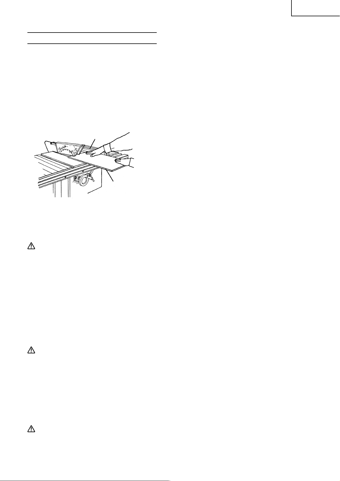
Français
INSTRUCTIONS D’UTILISATION
Il existe deux coupes de base. La coupe de fil et la coupe de mise à longueur. En général, on dit que couper
dans le sens du bois, c’est couper de fil, et que couper perpendiculaire au sens du bois, c’est couper pour
mettre à longueur. Ni la coupe de fil ni la coupe de mise à longueur ne peuvent se faire à mains libres. La
coupe de fil exige l’utilisation du guide de coupe de fil et la coupe de mise à longueur l’utilisation du guide
de coupe d’onglet. Des lunettes de sécurité sont portées dans un cas comme dans l’autre.
TOUJOURS UTILISER UNE PROTECTION DES YEUX LORSQUE L’ON TRAVAILLE AVEC L’OUTIL ÉLECTRIQUE
POUR ÉVITER UNE BLESSURE AUX YEUX.
Les lunettes à vue ordinaires n’offrent pas la protection adéquate du fait que les lentilles ne sont pas réalisées
dans un verre de sécurité. Par ailleurs, utiliser un masque facial par mesure supplémentaire et porter un
masque à poussière si le travail de coupe produit de la poussière.
1. Coupe de fil
Guide de coupe de fil
Pièce
Fig. 25
Contrôler les points suivants avant de couper de fil.
(1) Le guide de coupe de fil est parallèle à la lame de scie.
(2) Le guide de coupe de fil est soigneusement fixé.
(3) Retirer le guide de coupe d’onglet.
(4) Le séparateur est correctement aligné avec la lame de scie.
(5) Les griffes antiretour fonctionnent correctement (voir Fig. 9-
d).
Opération de coupe
q Régler la hauteur de la lame de scie de manière qu’elle soit à
3,2 mm (1/8") au-dessus du sommet de la pièce.
w Maintenir la pièce à plat sur la table et contre le guide de coupe
de fil. Tenir la pièce environ 25 mm (1") loin de la lame de
scie.
ATTENTION: La pièce doit présenter un bord droit contre le guide de coupe de fil et ne doit pas être
voilée, tordue ou bombée. Tenir les deux mains loin de la lame de scie et loin de la
trajectoire de la lame de scie.
e Placer l’interrupteur sur marche et attendre que la lame de scie ait atteint la vitesse.
r Tout en gardant la pièce contre la table et le guide de coupe de fil, avancer lentement la pièce vers
l’arrière complètement à travers la lame. Continuer de pousser la pièce jusqu’à ce qu’elle échappe à la
protection et tombe à l’arrière de la table.
t Pour la coupe de fil de panneaux longs ou larges, toujours utiliser un support adéquat.
Un simple support peut être préparé en fixant un morceau de contreplaqué à l’aide d’un serre-joint ou
de quelque chose de similaire.
y Quand la largeur de la coupe de fil est supérieure à 152 mm (6"), faire avancer la pièce à l’aide d’une
main ou des deux mains de manière continue jusqu’à ce qu’elle soit derrière la lame de scie et les griffes
antiretour.
ATTENTION: Ne pas pousser le morceau libre qui est coupé, le guider simplement.
u Quand la largeur de la coupe de fil est comprise entre 50 mm (2") et 152 mm (6"), utiliser un poussoir-
martyr pour faire avancer la pièce. (Le poussoir-martyr est un accessoire en option).
i Quand la largeur de la coupe de fil est inférieure à 50 mm (2"), utiliser un guide auxiliaire un bloc de
poussée.
o Lorsque l’on coupe de fil des matériaux fins (tel que le placage), la pièce peut glisser ou se courber entre
le fond du guide de coupe de fil et la surface de la table, ce qui rend la coupe de fil impossible. Couper un
panneau de même hauteur et de même longueur que la surface du guide de coupe de fil en utilisant un
morceau de contreplaqué de 19 mm (3/4") d’épaisseur. Fixer le panneau au guide de coupe de fil au
moyen de quatre vis à bois, de manière que le fond du panneau touche la surface de la table.
AVERTISSEMENT: Ne pas faire fonctionner pour tirer la pièce en arrière alors que la lame de scie
tourne. Mettre le contacteur sur arrêt, attendre que la lame de scie soit arrêtée,
soulever les griffes antiretour (voir Fig. 9-d) de chaque côté du séparateur si
nécessaire et faire glisser la pièce.
47
Page 48

Français
2. Coupe de fil en biseau
Cette opération est la même que la coupe de fil à ceci près que l’angle d’inclinaison est réglé à une
valeur autre que 0°.
AVERTISSEMENT: Ne travailler qu’avec la pièce et le guide de coupe de fil à droite de la lame de
3. Coupe de fil de petites pièces
AVERTISSEMENT: Il est peu sûr de couper de fil des petites pièces. Il est peu sûr de mettre les
Pièce Poussoir-martyr
Fig. 26
scie.
mains près de la lame de scie.
Quand une faible largeur doit être coupée de fil et la main ne
peut pas être placé sans danger entre la lame de scie et le guide
de coupe de fil, utiliser un ou plusieurs poussoirs-martyrs. Les
utiliser pour maintenir la pièce contre la table et le guide de coupe
de fil et pousser la pièce pour qu’elle dépasse complètement la
lame de scie.
Guide de
coupe de
fil
4. Coupe de mise à longueur
Guide de coupe
d’onglet
Pièce
Fig. 27
Contrôler les points suivants avant de réaliser une coupe de mise
à longueur.
(1) Retirer le guide de coupe de fil.
(2) Le séparateur est correctement aligné avec la lame de scie.
(3) Les griffes antiretour fonctionnent correctement (voir Fig. 9-
d)
Opération de coupe
q Régler la hauteur de la lame de scie de manière qu’elle soit à
3,2 mm (1/8") au-dessus du sommet de la pièce.
w Maintenir la pièce à plat sur la table et contre le guide de coupe
d’onglet. Tenir la pièce environ 25 mm (1") loin de la lame de
scie.
ATTENTION: Tenir les deux mains loin de la lame de scie et loin de la trajectoire de la lame de scie.
e Placer le contacteur sur marche et attendre que la lame de scie ait atteint la vitesse.
r Tout en gardant la pièce contre la table et le guide de coupe d’onglet, avancer lentement la pièce vers
l’arrière complètement à travers la lame.
ATTENTION: Ne pas faire fonctionner pour tirer la pièce en arrière alors que la lame de scie tourne.
Mettre l’interrupteur sur arrêt, attendre que la lame de scie soit arrêtée, soulever les
griffes antiretour de chaque côté du séparateur si nécessaire et faire glisser la pièce.
5. Coupe de mise à longueur en biseau
Cette opération est la même que la coupe de mise à longueur à ceci près que l’angle d’inclinaison est
réglé à une valeur autre que 0°.
AVERTISSEMENT: Ne travailler qu’avec la pièce et le guide de coupe d’onglet à droite de la lame de
scie.
6. Coupe d’onglet
Cette opération est la même que la coupe de mise à longueur à ceci près que le guide de coupe d’onglet
est réglé à une valeur autre que 90°.
48
Page 49

Français
Guide de coupe d’onglet
AVERTISSEMENT: Maintenir la pièce solidement contre
le guide de coupe d’onglet et faire
avancer la pièce lentement dans la
lame de scie pour éviter que la pièce
bouge.
Pièce
Fig. 28
7. Coupe d’onglet composée
Il s’agit d’un mélange de coupe de mise à longueur en biseau et de coupe d’onglet. Elle est peu fréquente.
Respecter les instructions pour la coupe de mise à longueur en biseau et celles pour la coupe d’onglet.
8. Aides au travail
Pour certaines opérations, des aides au travail telles que des poussoirs-martyrs, les blocs de poussée,
des guides auxiliaires, des supports et d’autres choses similaires, sont utilisés.
Ces aides peuvent être réalisés par l’utilisateur en se servant de la scie de table.
Se reporter aux Fig.s suivantes qui donnent des dimensions typiques d’aides au travail.
3/4"
(1) Poussoir-martyr
Quand la largeur de la coupe de fil est comprise entre 50 mm
(2") et 152 mm (6"), utiliser un poussoir-martyr pour faire
avancer la pièce. Le poussoir-martyr est un accessoire en
option (se reporter à la page 36). Un poussoir-martyr peut
aisément être réalisé à l’aide d’un morceau de contreplaqué
de 19 mm (3/4") d’épaisseur.
1-1/4"
1/2"
1-1/4"
1-1/4"
45°
12"
1"
4-3/4"
12"
A
Cette face et ce
bords doivent
être parallèle.
Fig. 29
(2) Bloc de poussée
Quand la largeur de la coupe de fil est inférieure à 50 mm (2"),
1"
12"
B
utiliser un bloc de poussée.
q Utiliser un morceau de contreplaqué de 9,5 mm (3/8") et
de 19 mm (3/4") d’épaisseur.
w Coller le petit morceau de bois 9,5 mm (3/8") × 19 mm
(3/8") × 63,5 mm (2-1/2").
e Prévoir une poignée au centre du contreplaqué et fixer
ensemble avec de la colle et des vis à bois.
r Les bords A et B doivent être parallèles.
3/8"
2-1/2"
5-1/8"
3/8"
5"
(3) Guide auxiliaire
Quand la largeur de coupe de fil est inférieure à 50 mm (2"),
Fig. 30
et que le poussoir-martyr ne peut pas être utilisé en raison de
la protection de lame de scie (voir Fig. 23) qui gêne le poussoirmartyr, utiliser un guide auxiliaire et le poussoir-martyr.
3/4"
2"
4-3/4"
20"
5-1/2"
3/4"
q Utiliser un morceau de contreplaqué de 9,5 mm (3/8") et
de 19 mm (3/4") d’épaisseur.
w Assembler les deux avec de la colle et des vis à bois.
ATTENTION: Le poussoir-martyr est utilisé avec le guide
auxiliaire. La dimension 121 mm (4-3/4") doit
être la même sur les deux.
Fig. 31
49
Page 50

Français
(4) Support de pièce
Contreplaqué
Attache “C”
q Fixer un morceau de contreplaqué sur un tréteau à l’aide
d’attaches en “C”.
w Régler la hauteur du contreplaqué pour qu’il soit à la
Tr éteau
Fig. 32
hauteur de la surface de la table.
9. Rainurage
AVERTISSEMENT: Pour éviter tout accident ou blessure corporelle, s’assurer que le contacteur est
sur la position d’arrêt et que la fiche du cordon d’alimentation est débranchée
avant de monter l’insert pour rainurage.
Ne jamais tenter d’empiler des lames à rainurage plus épaisse que 12,7 mm (1/2") d’épaisseur. Ne jamais
utiliser l’ensemble à rainurage pour coupes de mise à longueur. Ne jamais tenter une coupe en biseau
quand on rainure. Ne jamais utiliser le rainurage si il y a une vibration (pleurage) ou un bruit étrange. Ne
jamais tenter de rainurage dans autre chose que du bois. Ne jamais placer les mains sur la lame de rainurage.
Prendre toute précaution pour empêcher le retour arrière de la pièce. Faire avancer la pièce doucement,
spécialement quand on coupe des rainures profondes et larges. Quand la tête de rainurage est masquée à
la vue tout en coupant, les mains ne doivent pas être au-dessus de la pièce. Quand on utilise une lame de
rainurage, l’ensemble de protection de lame de scie doit être retiré étant donné qu’il n’y a pas de coupe à
travers tout le bois qui permettrait au séparateur de passer à travers la pièce.
ATTENTION: Faire extrêmement attention quand on procède à un rainurage.
Toujours arrêter l’outil électrique et attendre que la lame de rainurage soit
complètement arrêtée. Alors simplement retirer le bois. Utiliser un poussoir-martyr.
Utiliser le guide de coupe de fil ou le guide de coupe d’onglet. Etre attentif aux possibles
effets de retour arrière. Respecter les recommandations du fabrication de jeu de lames
de rainurage. Quand on utilise un jeu de lames de rainurage, la profondeur de coupe
n’est pas indiqué par le repère. Pour connaître la profondeur de coupe, on doit la
mesure avec une règle. Veiller à replacer l’ensemble de protection de lame de scie
dans sa position d’origine et à contrôler les réglages lorsque les rainurages sont
terminés.
Une rainure dans une pièce est appelée une rainure. Cette rainure ne s’étend pas complètement à travers la
pièce. La rainure peut avoir plusieurs largeurs et plusieurs profondeurs selon les besoins. Une utilisation
typique d’un rainurage est pour disposer d’une rainure pour une étagère. Une lame de scie peut être utilisée
pour faire un rainurage de n’importe quelle largeur en marquant des coupes multiples côte à côte. Toutefois,
il est préférable d’utiliser une lame à rainurer. La première a deux petites lames et une série de dents pour
retirer les débris entre les lames. Le second type consiste en une petite lame épaisse qui tremble par ses
moyeux. Cette scie accepte les lames à rainurer du type à couper les copeaux de 152 mm (6") de diamètre
et 12,7 mm (1/2") de large. La plupart des lames à rainurer tremblantes sont trop larges pour se monter sur
l’axe de cette scie en toute sécurité. Une lame à rainurer exige un insert de table qui a une ouverture plus
large. Cette insert à rainurage est disponible comme accessoire en option (voir page 36). Acheter la lame à
rainurer séparément.
Montage de l’ensemble de lame à rainurer
Pièce
Couteau à rainurer
Fig. 33
Monter l’ensemble de lame à rainurer (voir Fig. 33) par la
procédure qui suit:
q Retirer l’ensemble de protection de lame de scie avec le
séparateur.
w Retirer l’insert de table.
e Démonter la lame de scie.
r Monter la lame à rainurer avec les dents dirigées vers le
bas à l’avant de la table (en utilisant les instructions avec
l’ensemble de lame à rainurer).
t Monter l’insert de la table à rainurer (en option) au lieu de
l’insert de table.
50
Page 51

ATTENTION: Tout en serrant l’écrou de positionnement (voir Fig. 34), veiller à maintenir un écartement
égal entre les extrémités des couteaux intérieurs. Tourner la lame à rainurer d’un tout
à la main pour s’assurer qu’elle n’est en contact avec rien avant le fonctionnement.
INSTALLATION ET RETRAIT DE LA LAME
AVERTISSEMENT: Pour éviter tout risque d’accident ou de blessure, toujours couper l’interrupteur
et débrancher la fiche de la prise secteur avant de retirer ou d’installer la lame.
1. Installation de la lame
(1) Tourner le volant (voir Fig. 1) à fond dans le sens des aiguilles
d’une montre et régler la lame de scie pour la hauteur de coupe
maximale (voir Fig. 14-a).
Clé hexagonale
Fig. 34
Clé
Lame de scie
Ecrou de
positionnement
(2) Serrer le levier de verrouillage d’inclinaison de la lame et
bloquer la lame de scie à 90°.
(3) Retirer l’insert de table de la table.
(4) Monter la rondelle (A), la lame de scie et la rondelle (A) dans
cette ordre sur l’axe de la lame de scie. (La lame de scie avec
les dents dirigées vers le bas à l’avant de la table.)
(5) Au moyen de la clé ouverte placer la clé sur les méplats de
l’axe de la lame de scie. Maintenir l’axe de la lame de scie
pour qu’il ne tourne pas et serrer l’écrou au moyen de la clé
hexagonale restante en tournant l’écrou de de positionnement
dans le sens des aiguilles d’une montre.
(6) Replacer l’insert de table sur la table.
Français
AVERTISSEMENT: Veiller à bien saisir l’écrou de positionnement au moyen de la clé hexagonale.
Une blessure grave peut survenir si la saisie glisse la clé hors de l’écrou et la
main vient toucher les bords affûtés de la lame de scie.
Lors du montage de la lame de scie, s’assurer que la marque de rotation de la
lame de scie et le sens de rotation de la lame de scie sont semblables.
Serrer l’écrou de positionnement de manière qu’il ne se desserre pas pendant le
fonctionnement. S’assurer que l’écrou de positionnement (voir Fig. 34) a été
convenablement serré avant de démarrer l’outil électrique.
2. Retrait de la lame
Démonter la lame en procédant dans l’ordre inverse de l’installation décrite au paragraphe 1 ci-dessus.
ENTRETIEN ET INSPECTION
AVERTISSEMENT: Pour éviter tout risque d’accident ou de blessure, toujours vérifier que
l’interrupteur est coupé et que la fiche d’alimentation est débranchée de la prise
secteur avant d’entretenir ou d’inspecter l’outil.
1. Inspection de la lame
Toujours remplacer la lame dès qu’elle présente des signes d’usure ou de dommage.
Une lame endommagée risque de provoquer des blessures, et une lame usée peut réduire le rendement
et provoquer une surcharge du moteur.
ATTENTION: Ne jamais utiliser de lame émoussée. Si la lame est émoussée, sa résistance à la pression
de la main appliquée par la poignée de l’outil a tendance à augmenter, ce qui rend le
fonctionnement de l’outil électrique peu sûr.
51
Page 52

Français
2. Inspecter les balais carbone (Fig. 35 et Fig. 36)
Les balais carbone du moteur sont des pièces consommables.
Si les balais en carbone sont usés, le moteur risque d’avoir des anomalies.
En conséquence, inspecter périodiquement les balais en carbone et les remplacer.
Vérifier les balais en carbone au bout des 50 premières heures d’utilisation avec un outil neuf ou après
l’installation d’un nouveau jeu de balais en carbone. Après la première vérification, examiner les balais
en carbone environ toutes les 10 heures d’utilisation jusqu’à ce qu’il soit nécessaire de les remplacer.
Si le carbone de l’un des balais est usé jusqu’à la limite de 5 mm de longueur, ou si le ressort ou le fil de
shunt sont brûlés ou endommagés de quelque façon que ce soit, remplacer les deux balais en carbone
(voir Fig. 35). Si les balais en carbone se révèlent encore bons quand on les a démontés, les remonter à
la même position qu’avant le retrait.
Par ailleurs, maintenir les balais carbone propres de façon qu’ils glissent régulièrement dans les portebalai. Les balais carbone sont faciles à retirer ; pour cela, retirer les têtes porte-balai (voir Fig. 36) avec un
tournevis à tête plate (signe moins).
Repère de limite
d’usure
44
Chapeau de balai
5 mm (3/16")
17 mm (43/64")
No. 44 indique les deux derniers
chiffres du numéro de code des
balais de charbon
Fig. 35 Fig. 36
Moteur
3. Inspection des vis de montage
Inspecter régulièrement chaque composant de l’outil électrique pour voir s’il n’est pas lâche.
Resserrer les vis de fixation des pièces lâches.
AVERTISSEMENT: Pour éviter toute blessure personnelle, ne jamais faire fonctionnement l’outil
électrique si un composant est desserré.
4. Inspection du bon fonctionnement de la protection de lame de scie
Avant chaque utilisation de l’outil électrique, contrôler le bon fonctionnement de l’outil électrique et de
la protection de lame de scie (voir Fig. 1) pour s’assurer qu’ils sont en bon état et qu’ils se déplacent
régulièrement. Ne jamais utiliser l’outil électrique si la protection de lame de scie ne fonctionne pas
convenablement et s’ils ne sont pas en bon état mécanique. S’assurer que les griffes antiretour sont
toujours affûtées de façon qu’elles s’enfoncent profondément dans la pièce et empêchent les retours
arrière. Si un dommage est survenu, le réparer promptement,
5. Nettoyer fréquemment la protection de lame de scie.
Essuyer la poussière déposée à l’intérieur du regard de la protection de lame de scie au moyen d’un
chiffon doux. N’utiliser aucun solvant (essence, diluant, etc.), les solvants endommagent les pièces en
plastique.
6. Remisage
A la fin de chaque utilisation de l’outil électrique, s’assurer que le contacteur est sur la position OFF, que
la fiche du cordon d’alimentation a été débranchée de la prise secteur, que la clé de sécurité a été retirée
et qu’elle a été soigneusement rangée dans un endroit sûr. Lorsque l’outil électrique n’est pas utilisé, le
ranger dans un endroit sec, hors de portée des enfants.
7. Graissage
Lubrifier les pièces mobiles et les pièces tournantes suivantes une fois par mois pour conserver l’outil
électrique en bonnes conditions de fonctionnement pendant longtemps (voir Fig. 1 et Fig. 2). Utiliser
l’huile machine conseillée.
Points de lubrification:
Partie mobile et tournante du volant
8. Nettoyage
Enlever périodiquement les copeaux et autres débris de la surface de l’outil électrique avec un chiffon
humide et savonneux. Pour éviter tout mauvais fonctionnement du moteur, le protéger de tout contact
avec l’huile ou l’eau.
52
Page 53

Français
SERVICE APRÈS-VENTE ET RÉPARATIONS
Tous les outils électriques de qualité finissent un jour par avoir besoin de réparations ou de remplacement
de pièces sous l’effet d’une usure normale. Pour garantir que seules des pièces de rechange agréées seront
utilisées et que le système de double isolation sera protégé, il faudra confier toutes les opérations d’entretien
(autres que l’entretien de routine) exclusivement à un SERVICE APRES-VENTE D’OUTILS ELECTRIQUES
HITACHI AGREE.
REMARQUE: Les spécifications sont sujettes à modification sans obligations de la part d’HITACHI.
53
Page 54

Español
INFORMACIÓN IMPORTANTE
Antes de utilizar o realizar cualquier trabajo de mantenimiento de esta herramienta eléctrica, lea y comprenda
todas las instrucciones de operación, las precauciones de seguridad, y las advertencias de este Manual de
instrucciones.
La mayoría de los accidentes producidos en la operación y el mantenimiento de una herramienta eléctrica
se debe a la falta de observación de las normas o precauciones de seguridad. Los accidentes normalmente
podrán evitarse reconociendo una situación potencialmente peligrosa a tiempo y siguiendo los
procedimientos de seguridad apropiados.
Las precauciones básicas de seguridad se describen en la sección “SEGURIDAD” de este Manual de
instrucciones y en las secciones que contienen las instrucciones de operación y mantenimiento.
Para evitar lesiones o el daño de la herramienta eléctrica, los riesgos están identificados con ADVERTENCIAS
en dicha herramienta y en este Manual de instrucciones.
No utilice nunca esta herramienta eléctrica de ninguna forma no específicamente recomendada por HITACHI
a menos que usted se haya asegurado de que la utilización planeada será segura para usted y otras personas.
SIGNIFICADO DE LAS PALABRAS CLAVE
ADVERTENCIA: indica situaciones potencialmente peligrosas que, si se ignoran, pueden resultar en
lesiones serias.
PRECAUCIÓN: indica situaciones potencialmente peligrosas que, si se ignoran, pueden resultar en
lesiones moderadas, o que pueden causar averías en la herramienta eléctrica.
NOTA: acentúa información esencial.
SEGURIDAD
NORMAS DE SEGURIDAD PARA LAS HERRAMIENTAS ELÉCTRICAS
LEA TODAS LAS ADVERTENCIAS E INSTRUCCIONES DE OPERACIÓN DE ESTE MANUAL
ANTES DE UTILIZAR ESTA HERRAMIENTA O DE REALIZAR TRABAJOS DE
MANTENIMIENTO EN LA MISMA.
ADVERTENCIA: Cuando utilice este herramienta eléctrica, tome todas las precauciones necesarias
para reducir al mínimo el riesgo de descargas eléctricas y demás lesiones. En
particular, observe siempre las normas de seguridad siguientes:
1. MANTENGA SIEMPRE LOS PROTECTORES EN SU LUGAR, y en perfectas condiciones de
trabajo.
2. ANTES DE PONER EN FUNCIONAMIENTO LA HERRAMIENTA, QUÍTELE TODAS LAS
CHAVETAS Y LLAVES DE AJUSTE. Antes de conectar la alimentación de la herramienta eléctrica,
confirme que todas las chavetas y llaves de ajuste estén extraídas de la misma.
3. MANTENGA SIEMPRE EL ÁREA DE TRABAJO LIMPIA. Evite lesiones debidas al desorden
del área y del banco de trabajo.
4. NO UTILICE NUNCA LA HERRAMIENTA EN AMBIENTES PELIGROSOS. No utilice nunca
la herramienta eléctrica en lugares húmedos, y no la exponga nunca a la humedad. Mantenga siempre
bien iluminada el área de trabajo.
5. NO PERMITA QUE LOS NIÑOS NI OTRAS PERSONAS ENTREN EN EL ÁREA DE
TRABAJO. Mantenga a las personas (especialmente los niños) alejadas del área de trabajo. Desenchufe
siempre las herramientas desatendidas y bloquee el área de trabajo instalando cerraduras en las puertas
y seguros en los interruptores principales. Cuando no esté utilizando la herramienta, extraiga siempre
la llave de seguridad del interruptor y guárdela en un sitio seguro.
6. NO FUERCE NUNCA LA HERRAMIENTA. La herramienta trabajará mejor y con mayor seguridad
si la utiliza con el régimen para el que fue diseñada.
54
Page 55

Español
7. UTILICE SIEMPRE LAS HERRAMIENTAS CORRECTAS. No fuerce nunca una herramienta ni
un accesorio para realizar un trabajo para el que no se haya diseñado.
8. ANTES DE TRABAJAR CON LA HERRAMIENTA, VÍSTASE LA ROPA ADECUADA. No
utilice nunca ropa floja, guantes, corbatas, collares, anillos, brazaletes, ni demás joyas que puedan
quedar atrapados en las partes móviles. Utilice siempre calzado antideslizable, preferiblemente con
punteras reforzadas con acero. Si tiene el pelo largo, recoja y cúbraselo.
9. ANTES DE UTILIZAR LA HERRAMIENTA, UTILICE GAFAS PROTECTORAS PARA EVITAR
DAÑAR SUS OJOS. Las gafas normales no proveen una protección suficiente debido a que sus
lentes son sólo resistentes a los impactos y NO son gafas de seguridad. Además, utilice una careta
como protección adicional, y utilice una máscara contra el polvo si la operación de corte produce
polvo.
10. ASEGURE SIEMPRE LA PIEZA DE TRABAJO EN LA ESCUADRA DE GUÍA O EN LA
MESA. Utilice abrazaderas o un tornillo de carpintero para sujetar la pieza de trabajo. Es más seguro
utilizar que utilizar su mano, porque podrá usar ambas para manejar la herramienta.
11. NO SE EXTRALIMITE NUNCA. Cuando trabaje con la herramienta, mantenga en todo momento
el equilibrio.
12. MANTENGA SIEMPRE LAS HERRAMIENTAS EN PERFECTAS CONDICIONES. Guarde
siempre las herramientas afiladas y limpias para que rindan al máximo y ofrezcan la mayor seguridad.
Siga siempre las instrucciones sobre lubricación y cambio de accesorios de las herramientas.
13. DESCONECTE SIEMPRE LA HERRAMIENTA antes de realizar la operación de mantenimiento y
de cambiar la hoja de sierra y demás accesorios.
14. TENGA CUIDADO CON LA PUESTA EN FUNCIONAMIENTO ACCIDENTAL AL
ENCHUFAR LA HERRAMIENTA. Antes de insertar el enchufe de alimentación en un tomacorriente,
cerciórese de que el interruptor esté en la posición OFF.
15. CON ESTA HERRAMIENTA SIEMPRE UTILICE SOLAMENTE LOS ACCESORIOS
RECOMENDADOS. Con respecto a la descripción sobre los accesorios recomendados, consulte el
manual de instrucciones. Para evitar lesiones, con esta herramienta, utilice solamente los accesorios
recomendados.
16. NO SE SUBA NUNCA SOBRE LA HERRAMIENTA. La caída de la herramienta o un contacto
involuntario con la hoja de sierra podría producir lesiones de gravedad.
17. ANTES DE UTILIZAR LA HERRAMIENTA, COMPRUEBE SI TIENE PARTES DAÑADAS.
Compruebe siempre si el protector y los demás componentes están dañados antes de utilizar la
herramienta para asegurarse de que funcionen adecuadamente. Compruebe si todas las partes móviles
están adecuadamente alineadas, no están dobladas, y no se encuentran en otras condiciones que puedan
afectar la operación apropiada. Antes de utilizar la herramienta, repare o reemplace siempre cualquier
protector o componente dañado.
18. ANTES DE UTILIZAR LA HERRAMIENTA, COMPRUEBE SIEMPRE EL SENTIDO DE GIRO
DE LA HOJA DE SIERRA. Alimente siempre la pieza de trabajo en la herramienta en sentido contrario
al de giro de la hoja de sierra a fin de evitar posibles lesiones.
19. NO DEJE LA HERRAMIENTA DESATENDIDA EN FUNCIONAMIENTO. DESCONECTE
LA ALIMENTACIÓN. No deje la herramienta mientras no se haya parado completamente. Cuando
no vaya a utilizar la herramienta, desenchufe su cable de alimentación.
20. Esta herramienta no ha sido diseñada para aplicaciones de producción en masa, y no deberá utilizarse
para ello.
21. Cuando tenga que remplazar esta herramienta, utilice solamente las piezas de reemplazo autorizadas.
22. Aplique solamente 115 voltios CA a esta unidad. Si le aplicase una tensión incorrecta, o tensión de CC,
la HERRAMIENTA ELÉCTRICA podría funcionar incorrectamente y causar lesiones o daños a la propia
herramienta.
23. PUESTA A TIERRA APROPIADA. Esta herramienta deberá estar conectada a tierra durante el uso
para proteger al operador contra electrochoques.
55
Page 56

Español
Normas de seguridad específicas para la utilización de esta
herramienta
ADVERTENCIA: Las instrucciones de operación específicas siguientes deberán observarse cuando
se utilice esta HERRAMIENTA ELÉCTRICA a fin de evitar lesiones.
LO QUE DEBERÁ HACERSE
TENGA SIEMPRE EN CUENTA LAS NORMAS SIGUIENTES PARA PODER UTILIZAR CON
SEGURIDAD ESTA HERRAMIENTA:
1. Antes de intentar utilizar esta HERRAMIENTA ELÉCTRICA, lea este manual y familiarícese con las normas
de seguridad y las instrucciones de operación.
2. Antes de utilizar la HERRAMIENTA ELÉCTRICA, confirme que esté limpia.
3. Para utilizar la HERRAMIENTA ELÉCTRICA, vístase ropa ajustada, calzado no deslizable (preferiblemente
con punteras reforzadas con acero) y gafas protectoras.
4. Maneje la HERRAMIENTA ELÉCTRICA con cuidado. Si la HERRAMIENTA ELÉCTRICA se cae o se golpea
contra un objeto duro, puede deformar o rajarse, o sufrir otros daños.
5. Si nota cualquier anormalidad, deje de utilizar inmediatamente la sierra.
6. Antes de utilizar la herramienta, compruebe si todos los componentes están montados adecuadamente
y con seguridad.
7. Cuando reemplace la hoja de sierra, confirme que las rpm de la nueva sean correctas para utilizarse
con esta unidad.
8. Antes de realizar cualquier trabajo de mantenimiento o ajuste, desconecte la alimentación y espere
hasta que la hoja de sierra se haya parado completamente.
9. Realice siempre una prueba antes de intentar utilizar una hoja de sierra nueva.
10. Maneje siempre la hoja de sierra con cuidado cuando la desmonte o monte.
11. Antes de utilizar la sierra, compruebe siempre si la pieza de trabajo está exenta de clavos y demás
objetos extraños.
12. Mantenga siempre las manos alejadas del trayecto de la hoja de sierra.
13. Confirme siempre que el protector de la hoja se encuentre en el sitio apropiado antes de utilizar la
sierra.
14. Antes de realizar el corte, siempre confirme que el protector de la hoja no obstaculice el movimiento
deslizante de la sierra.
15. Inspeccione periódicamente el cable de alimentación de la herramienta.
16. Antes de poner en funcionamiento la herramienta, confirme si la longitud del cable de alimentación y
de los cables prolongadores, si va a utilizarlos, es apropiada.
17. Antes de utilizar la herramienta, confirme que los orificios de ventilación del motor estén completamente
abiertos.
18. Antes de comenzar a cortar, espere siempre hasta que el motor haya alcanzado la velocidad plena.
19. Mantenga siempre las empuñaduras secas, limpias, y exentas de aceite y grasa. Cuando utilice la
herramienta, sujétela firmemente.
20. Utilice siempre el protector de la hoja, la placa abridora o el seguro antirretroceso en todas las operaciones
de “aserrado al largo”. Las operaciones de aserrado al largo son aquellas en que la hoja corta
completamente a través de la pieza de trabajo, como en el aserrado al hilo o el corte transversal.
21. Siempre sujete firmemente la pieza de trabajo contra la guía de ingletes o el tope-guía.
22. Siempre utilice la varilla de empuje para cortar al hilo materiales angostos. Refiérase a las operaciones
de corte al hilo del manual de instrucciones donde se explica detalladamente la varilla de empuje.
23. Extraiga el tope-guía durante el corte transversal.
24. Para piezas de trabajo largas o anchas, provea un soporte adecuado en las partes laterales y trasera de
la mesa de sierra.
56
Page 57

Español
25. Evite los retrocesos (hacer retroceder la pieza de trabajo hacia usted).
Mantenga la hoja de sierra afilada y el tope-guía paralelo a la hoja de sierra.
Mantenga en su sitio la placa abridora, los seguros antirretroceso y el protector de la hoja durante la
operación. Antes de empujar completamente la pieza de trabajo más allá de la hoja de sierra, compruebe
que el corte al hilo no esté torcido ni alabeado y que el borde recto le guíe a lo largo del tope-guía.
26. Evite las posturas incómodas y nunca coloque sus manos en un sitio en que puedan entrar
accidentalmente dentro de la herramienta de corte debido a un movimiento inesperado.
27. Antes de realizar las operaciones de corte, asegúrese de armar correctamente la mesa de sierra. Refiérase
a las instrucciones de instalación.
28. Siempre utilice la herramienta en un sitio bien ventilado. Elimine frecuentemente el serrín.
Elimine el serrín acumulado dentro de la mesa de sierra para evitar toda posibilidad de incendio.
29. Las instrucciones de funcionamiento proporcionadas con la herramienta deberán indicar al usuario
cómo asegurar la herramienta a la estructura de soporte si, durante la operación normal, tiende a
volcarse, deslizarse o desplazarse sobre la superficie de soporte.
LO QUE NO DEBERÁ HACERSE
NO VIOLE NUNCA LAS NORMAS SIGUIENTES PARA PODER UTILIZAR CON SEGURIDAD
ESTA HERRAMIENTA:
1. No utilice nunca la HERRAMIENTA ELÉCTRICA a menos que haya comprendido completamente las
instrucciones de operación contenidas en este manual.
2. No deje nunca la HERRAMIENTA ELÉCTRICA desatendida sin haber desenchufado antes el cable de
alimentación.
3. No utilice nunca la HERRAMIENTA ELÉCTRICA cuando esté cansado, después de haber ingerido
medicamentos, o cuando haya tomado bebidas alcohólicas.
4. No utilice nunca la HERRAMIENTA ELÉCTRICA para aplicaciones no especificadas en este manual.
5. No utilice nunca la herramienta con ropa floja, corbata, ni joyas, ni sin haberse cubierto el pelo para
evitar que puedan quedar atrapados en las partes móviles.
6. No acerque las manos a la hoja de sierra.
7. No toque nunca las partes móviles, incluyendo la hoja de sierra, mientras esté utilizando la sierra.
8. No quite nunca ningún dispositivo de seguridad ni los protectores de la hoja de sierra, ya que la utilización
de la herramienta sin ellos podría resultar peligrosa.
9. No bloquee nunca el protector de la hoja y siempre asegúrese de que se desliza suavemente antes de
utilizar la herramienta.
10. No dañe nunca el cable de alimentación de la herramienta.
11. No intente mover nunca una HERRAMIENTA ELÉCTRICA con el dedo en el interruptor de disparo.
12. No intente nunca utilizar la HERRAMIENTA ELÉCTRICA si el interruptor de disparo no funciona
adecuadamente.
13. No utilice nunca la HERRAMIENTA ELECTRICA si la envoltura de plástico o el protector de la hoja se
encuentra agrietado o deformado.
14. No utilice nunca la HERRAMIENTA ELÉCTRICA cerca de líquidos ni gases inflamables porque las chispas
podrían causar una explosión.
15. No limpie nunca los componentes de plástico con disolventes, porque el plástico podría disolverse.
16. No utilice nunca la sierra de mesa a menos que el protector de la hoja esté colocado en su lugar.
17. No levante nunca la hoja de sierra de la pieza de trabajo mientras no se haya parado completamente.
18. No utilice nunca hojas de tipo abrasivo con esta herramienta.
19. No efectúe nunca una operación de “manos libres”; utilice siempre sus manos para soportar o guiar la
pieza de trabajo. Siempre trabaje con la ayuda del tope-guía o de la guía de ingletes.
20. No coloque ninguna parte de su cuerpo en la trayectoria de la hoja de sierra.
21. No coloque nunca su mano sobre o detrás la herramienta de corte.
22. No utilice nunca el tope-guía como galga de corte durante el corte transversal.
23. No intente nunca desenganchar una hoja de sierra atascada sin haber apagado previamente la sierra.
24. No corte nunca metales ni materiales que puedan producir polvos peligrosos.
25. No corte nunca metales ferrosos ni mamposteía.
57
Page 58

Español
ADVERTENCIA
PARA SU PROPIA SEGURIDAD, ANTES DE UTILIZAR ESTA SIERRA DE MESA
LEA ESTE MANUAL DE INSTRUCCIONES.
1. Utilice siempre gafas protectoras cuando trabaje con la sierra de mesa.
2. Utilice el protector de la hoja y la placa abridora en todas las operaciones, incluyendo el aserrado al
largo.
3. Mantenga siempre las manos fuera del trayecto de la hoja de sierra.
4. Utilice siempre la varilla de empuje cuando se requiera su empleo.
5. Preste especial atención a las instrucciones para reducir el riesgo de retrocesos.
6. No efectúe ninguna una operación de manos libres con la sierra de mesa.
7. No se acerque nunca a la hoja de sierra.
PIEZAS DE REEMPLAZO
Para la reparación de una herramienta, utilice solamente piezas de reemplazo idénticas.
Las reparaciones solamente deberán realizarse en un centro de servicio autorizado por Hitachi.
UTILIZACIÓN DE UN CABLE PROLONGADOR
Utilice únicamente cables prolongadores de tres hilos que tengan un enchufe del tipo de puesta a tierra de
tres clavijas y un tomacorriente tripolar adecuado para el enchufe. Reemplace o repare inmediatamente un
cable dañado o gastado.
Cerciórese de que el cable prolongador esté en buenas condiciones. Cuando utilice un cable prolongador,
cerciórese de que tenga el calibre (grosor) suficiente como para poder conducir la corriente necesaria para
la herramienta. Un cable de calibre inferior causaría la caída de tensión, lo que resultaría en pérdida de
potencia y en recalentamiento. En la tabla siguiente se indica el calibre correcto de acuerdo con la longitud
del cable y la indicación de amperaje de la tabla de características. Cuando menor sea el número de calibre,
mayor será el cable.
Antes del uso, verifique que los cables de alimentación y los cables prolongadores no estén deshilachados
ni con el aislamiento dañado. Antes de utilizar la herramienta, repare o reemplace según se requiera.
CALIBRE MÍNIMO PARA CABLES
Longitud total del cable en pies (metros)
0 – 25 26 – 50 51 – 100 101 – 150
(0 – 7,6) (7,9 – 15,2) (15,5 – 30,5) (30,8 – 45,7)
Amperaje nominal AWG
Más No más
de de
0 – 6 18161614
6 – 10 18 16 14 12
10 – 12 16 16 14 12
12 – 16 14 12 No se recomienda.
ADVERTENCIA: Evite descargas eléctricas. No utilice nunca esta herramienta con un cable de
alimentación o prolongador dañado ni reparado.
Inspeccione regularmente todos los cables eléctricos. No utilice nunca la herramienta
cerca del agua ni en ningún otro lugar en el que exista el riesgo de descargas
eléctricas.
58
Page 59

Español
AISLAMIENTO DOBLE PARA OFRECER UNA OPERACIÓN MÁS SEGURA
HERRAMIENTAS COMPLETAMENTE CONECTADAS A TIERRA, CON CONEXION POR CABLE: En el caso de
falla de funcionamiento o de caída de línea, la puesta a tierra proporciona una vía de menor resistencia a la
corriente eléctrica para reducir el riesgo de sacudidas eléctricas. Esta herramienta cuenta con un cordón
eléctrico provisto de un conducto de puesta a tierra y de un enchufe con conexión a tierra. El enchufe debe
insertarse en un tomacorriente coincidente que haya sido correctamente instalado y conectado a tierra de
conformidad con todas las normas y reglamentos locales. No modifique el enchufe suministrado – si no
coincide con el tomacorriente, contacte con un electricista especializado a fin de que se lo reemplace por
otro apropiado. Una conexión inapropiada del conducto de puesta a tierra del equipo puede producir
sacudidas eléctricas. El conductor con el aislamiento exterior verde con o sin rayas amarillas es el conductor
de puesta a tierra del equipo. Cuando sea necesario reparar o reemplazar el cable eléctrico o el enchufe, no
conecte el conductor de puesta a tierra a un terminal activo.
Cerciórese de haber observado todas las instrucciones de puesta a tierra y consulte con un electricista
especializado o con el personal de servicio cuando tenga dudas sobre la conexión a tierra de la herramienta.
Utilice únicamente cables prolongadores de 3 hilos que tengan un enchufe de puesta a tierra de 3 clavijas y
tomacorrientes de 3 polos que coincidan con el enchufe. Repare o reemplace inmediatamente un cable
dañado o gastado.
Herramientas conectadas a tierra, con conexión por cable para utilizarse con un circuito de alimentación
con un régimen nominal de menos de 150 voltios: Esta herramienta es para enchufarse en un tomacorriente
como el mostrado en la Fig. A. La herramienta cuenta con un terminal de tierra como el mostrado en la Fig.
A. Si no dispone de un tomacorriente con toma de tierra, se podría utilizar un adaptador temporal, como el
indicado en las Figs. B y C para conectar este enchufe a un tomacorriente de 2 polos como el mostrado en
la Fig. B. El adaptador temporal debe utilizarse únicamente hasta que un electricista especializado le instale
el tomacorriente con toma de tierra apropiado. La orejeta rígida de color verde o similar que se extiende
desde el adaptador debe ser conectada a una tierra permanente como una caja de salida debidamente
conectada a tierra.
METODOS DE PUESTA A TIERRA
Fig. A Fig. B Fig. C
Tornillo de
metal
Cubierta de la caja
de salida conectada
a tierra
Terminal de tierra
Contacto a tierra
GUARDE ESTAS INSTRUCCIONES
A MANO PARA QUE PUEDAN
CONSULTARLAS OTROS QUE DESEEN
UTILIZAR ESTA HERRAMIENTA
Adaptador
59
Page 60
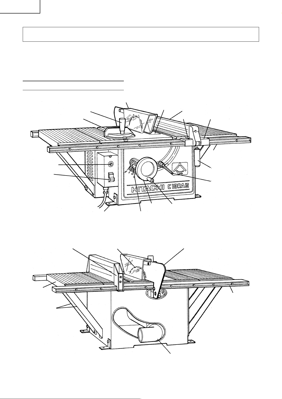
Español
OPERACIÓN Y MANTENIMIENTO
NOTA: La información contenida en este manual ha sido diseñada para ayudarle a realizar una operación
segura y a mantener la HERRAMIENTA ELÉCTRICA. Algunas ilustraciones de este manual pueden
mostrar detalles o dispositivos diferentes a los de su propia HERRAMIENTA ELÉCTRICA. Además,
en algunas ilustraciones, los protectores y cubiertas no se muestran intencionadamente por
motivos de ilustración solamente.
NOMENCLATURA DE PARTES
Conjunto de protector de la hoja
Botón de
reposición
Interruptor
Mango de sujeción (B)
Guía de ingletes
Placa de ajuste
(accesorio estándar)
Indicador de aguja
Fig. 1
Inserto Tope-guía
Indicador
Mango de la ruedaRueda
Cuerpo de anchura
Riel delantero
Empuñadura
Mango de bloqueo del
eje de inclinación
60
Aleta de
prolongación
Sujetador de
prolongación
Soporte
Hoja de sierra
Placa abridora
Riel trasero
Codo (accesorio estándar)
Fig. 2
Page 61
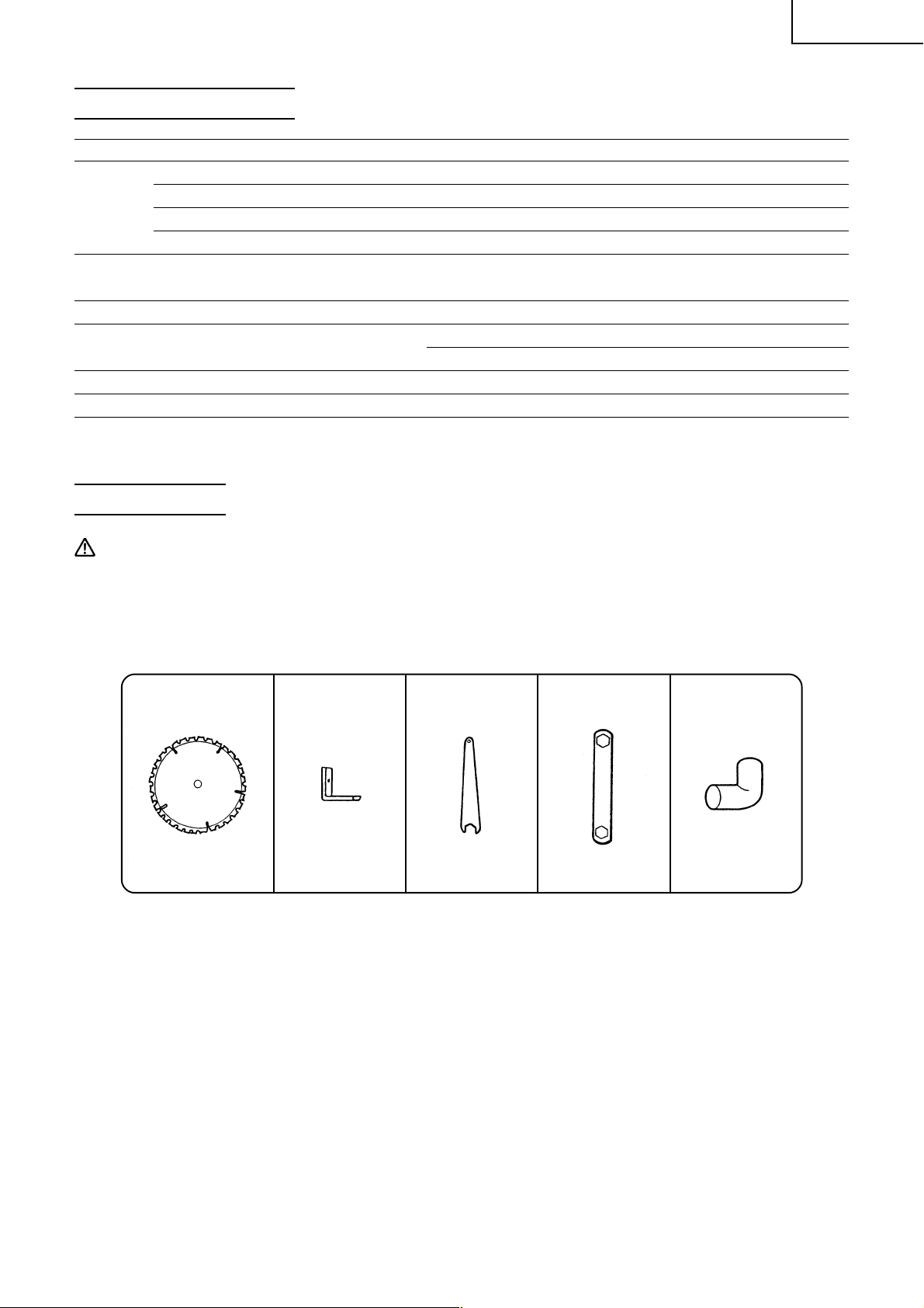
ESPECIFICACIONES
Item Modelo: C10RA2
Tipo Motor conmutador en serie
Motor
Hoja de sierra aplicable Diámetro exterior: 255 mm (10")
Velocidad sin carga 5000 rpm
Dimensión máx. de corte 90° Altura máx 3"
Peso neto 29 kg (64 lbs)
Cable Cable del tipo de 3 conductores de 2 m (6,6 pies)
Fuente de alimentación Monofásica, CA, 60Hz
Tensión (voltios) 115
Corriente a plena carga (amperios) 15
Diámetro del orificio: 15,9 mm (5/8")
Bisel 45° Altura máx. 2 – 1/2"
Español
ACCESORIOS
ADVERTENCIA: Los accesorios para esta herramienta eléctrica se mencionan en este Manual de
instrucciones.
La utilización de otros accesorios puede resultar peligrosa y causar lesiones o daños
mecánicos.
ACCESORIOS ESTÁNDAR
q Hoja de sierra TCT w Placa de ajuste e Llave r Llave hexagonal t Codo
de 255 mm (10") (4 piezas) (1 pieza) (1 pieza) (1 pieza)
(1 pieza)
Con respecto al Con respecto al
uso, consulte la uso, consulte la
página 63. página 66.
Fig. 3
61
Page 62

Español
ACCESORIOS OPCIONALES ... De venta por separado
q Inserto de ranurar (para la cuchilla de ranurar) (Núm. de código 314325) Conveniente para ranurar.
Refiérase a la lista de piezas.
w Varilla de empuje (Núm. de código 314324) Conveniente para corte al hilo de piezas pequeñas. Refiérase
a la lista de piezas.
e Soporte de la sierra de mesa (Núm. de código 314819) Conveniente para ajustar la sierra de mesa.
Refiérase a la Fig. 12-c.
ADVERTENCIA: El peligroso utilizar aditamentos o accesorios no recomendados en este manual y
su utilización podría provocar lesiones personales o daños a la sierra.
APLICACIONES
Madera (maderas duras o blandas)
DESEMBALAJE
La herramienta se entrega junto con las piezas representadas en la Fig. 4. Al efectuar el desembalaje,
compruebe que se le han entregado todas las piezas indicadas.
12
14
15
13 10 9
12 11
3
56
7
4
8
Fig. 4
1. Guía de ingletes (1 pieza) 8. Empuñadura (1 pieza)
2.
Conjunto de protector de hoja y placa abridora (1 pieza)
9. Perno de 6 × 90 mm (1 pieza)
3. Codo (1 pieza) 10. Perno de 6 × 110 mm (1 pieza)
4. Tope-guía (1 pieza) 11. Arandela elástica de 6 mm (2 piezas)
5. Llave hexagonal (1 pieza) 12. Arandela plana de 6 mm (2 piezas)
6. Llave (1 pieza) 13.
Perno de 8 × 20 mm (con / arandelas) 4 piezas)
7. Mango de la rueda (1 pieza) 14. Placa de ajuste (4 piezas)
15. Almohadilla (1 pieza)
62
Page 63

Español
PREPARATIVOS PREVIOS A LA OPERACIÓN
Antes de utilizar la herramienta eléctrica, realice los preparativos siguientes.
1. Instalación
La sierra de mesa debe de estar correctamente asegurada a un banco de trabajo, soporte o gabinete
robusto.
Las ruedas (de proveerse) del banco de trabajo, soporte o gabinete deben mantenerse frenadas durante
la operación.
Si advierte que la sierra de mesa tiende a moverse durante la operación, corrija inmediatamente.
(1) Coloque la sierra de mesa en el lugar deseado.
Agujeros de 8 mm
Marcas de
posición para la
placa de ajuste
(5/16")
400 mm (15-3/4")
Fig. 5
Corte cuadrado de
305 mm (12") (central)
450 mm (17-23/32")
Banco de trabajo,
soporte o gabinete
(3) Extraiga la sierra de mesa y coloque una escuadra de 279 mm (11") o 305 mm (12") centrándola entre las
marcas de posición del cuerpo. Realice el corte y saque la escuadra. Esta abertura evitará que el serrín
se acumule dentro del cuerpo principal.
Asegúrese de que haya un espacio adecuado en todo
el rededor de la sierra de mesa.
Para asegurar una máxima flexibilidad al trabajar con
tableros y tablas largas, se recomienda proveer un
huelgo de 2745 mm (9 pies) en los cuatro costados de
la sierra de mesa.
(2) Fije las cuatro placas de ajuste en las cuatro esquinas
de la base de la sierra por medio de cuatro pernos de
8 × 20 mm (con/arandelas) y cuatro tuercas de 8 mm.
Asegure la sierra de mesa al banco de trabajo, soporte
o gabinete. Asegúrese de poder acceder fácilmente a
todos los mandos y de proveer un huelgo de por lo
menos 170 mm (6-11/16") detrás de la mesa para el
conjunto del protector de la hoja.
Marque temporalmente la posición de las cuatro
esquinas de la base y de las placas de ajuste de la
sierra de mesa.
PRECAUCIÓN: Sin esta abertura se producirá una entrada insuficiente de aire de enfriamiento al
motor, provocando fallas prematuras del mismo además de riesgos de incendio.
(4) Recoloque la sierra de mesa, alineándola con las marcas realizadas anteriormente. En el banco de trabajo,
soporte o gabinete trace con un lápiz o similar las posiciones de los agujeros para las cuatro placas de
ajuste.
(5) Retire la sierra de mesa y perfore un agujero de 8 mm (5/16") en cada uno de los sitios marcados.
Elimine completamente el serrín y las virutas.
(6) Recoloque la sierra de mesa en el sitio marcado. Verifique que la sierra de mesa no se bloquee en el
banco de trabajo y que las cuatro placas de ajuste estén en contacto con la parte superior del banco de
trabajo, soporte o gabinete.
(7) Utilice cuatro pernos de 50 mm (2"), tuercas y arandelas planas (no suministrados) del tamaño adecuado
para asegurar la sierra de mesa al banco de trabajo, gabinete o soporte. Coloque una arandela elástica
y una arandela plana en el perno, introduzca éste a través del agujero de la placa de ajuste y del banco
de trabajo, soporte o gabinete. Añada otra arandela plana y una tuerca. No apriete todavía la tuerca.
Repita esta operación en los tres lugares restantes. Apriete firmemente todas las tuercas.
(8) Compruebe que la sierra haya quedado firmemente instalada.
63
Page 64

Español
PROCEDIMIENTOS DE ARMADO
ADVERTENCIA: Para evitar accidentes o lesiones, siempre asegúrese de desconectar el interruptor
y de extraer el enchufe del tomacorriente antes de ensamblar esta herramienta.
1. Armado del mango de la rueda
Rueda
Mango de la rueda
Fig. 6
El mango de la rueda permite girar la rueda con mayor rapidez.
Una vez que esté correctamente ensamblada, girando libremente
pero con un juego muy pequeño,
(1) Apriete el tornillo del mango de la rueda hasta que entre en
contacto con la rueda.
(2) Apriete firmemente la tuerca del mango de la rueda con una
llave.
2. Instalación del tope-guía
PRECAUCIÓN: El tope-guía debe estar alineado paralelamente a la hoja de sierra para minimizar el
riesgo de retrocesos (refiérase a la página 72).
El tope-guía puede utilizarse convenientemente para cortar una
Soporte
pieza en otras de un ancho preciso o en piezas paralelas. Puede
montarse tanto en el lado derecho como en el lado izquierdo de
Riel trasero
la mesa.
(1) Apriete el tornillo de la empuñadura.
(2) Enganche el gancho del soporte en la parte inferior del riel
trasero.
(3) Baje el tope-guía en la dirección de la flecha y fije la parte del
Empuñadura
Cuerpo de
anchura
Riel
delantero
Fig. 7
cuerpo de anchura y del soporte en la ranura de los rieles
delantero y trasero.
(4) Confirme que el tope-guía puede moverse suavemente hacia
la derecha y la izquierda.
3. Armado de la guía de ingletes
Ranura de la guía de ingletes
La guía de ingletes es conveniente para cortar piezas largas o en
ángulo difíciles de trabajar con el tope-guía. Puede montarse en
cualquiera de los lados derecho o izquierdo de la mesa. Alinee la
barra plana de la guía de ingletes con la ranura de la guía de
ingletes y deslícela en la dirección indicada por la flecha a través
de la parte delantera de la mesa.
Barra plana
Guía de
ingletes
64
Fig. 8
Page 65

4. Montaje y ajuste del conjunto del protector de la hoja de sierra
Español
Levantar
Ménsula del
protector
Hoja de sierra
Borde recto
Hoja de
sierra
Rueda
Menos de
12,7 mm (1/2")
Hoja de sierra
Bajar
Apretar
Mango de bloqueo
Fig. 9-a
Fig. 9-b
Fig. 9-c
de inclinación
Perno de
6 × 90 mm
Perno de
6 × 110 mm
Seguro
antirretroceso
Aflojar
Placa abridora
Placa
abridora
PRECAUCIÓN: El conjunto de protector de hoja y de placa
abridora debe estar correctamente
alineado con la hoja de sierra para evitar
el retroceso.
Instale el conjunto del protector de la hoja de sierra, incluyendo
la placa abridora y los seguros antirretroceso (véase Fig. 9-d).
(1) Montaje de la placa abridora
q Afloje el mango de bloqueo de inclinación de la hoja de
sierra, mueva el mecanismo de inclinación hacia la
izquierda y haga que la hoja de sierra quede ajustada a 0°
mediante el tope. Apriete el mango de bloqueo de
inclinación de la hoja de sierra para que quede bloqueado
en su lugar.
w Gire completamente la rueda en el sentido de las agujas
del reloj y ajuste la hoja de sierra a la altura máxima de
corte (véase Fig. 9-a).
e Coloque una arandela elástica de 6 mm y una arandela
plana D13 en los pernos de 6 × 90 mm y de 6 × 110 mm.
r Sujete temporalmente la placa abridora sobre la sección
trasera del cuerpo utilizando la almohadilla y los dos
pernos de 6 mm mencionados más arriba (véase Figs.9-b
y 9-d).
(La ménsula del protector debe ser fijada de antemano a
la placa abridora).
(2) Ajuste de la placa abridora
q Utilice un borde recto para alinear la placa abridora con la
hoja de sierra (véase Fig. 9-c).
Apriete con una llave los dos pernos de 6 × 16 mm (véase
Fig. 9-d) para que la placa abridora quede bloqueada.
w Verifique el huelgo entre la punta de la hoja de sierra y la
placa abridora. El huelgo debe ser inferior a 12,7 mm
(1/2") en todas las posiciones. Si no es así, afloje con una
llave los dos pernos de 6 × 16 mm que aseguran la placa
abridora a la ménsula de protector y mueva la placa
abridora hacia arriba y abajo. Después de ajustar la placa
abridora, reapriete firmemente los dos pernos de 6 × 16
mm con una llave (véase Fig. 9-d).
Almohadilla
Fig. 9-d
5. Montaje del inserto de mesa
Tornillo para
Mesa
metales de 5 mm
Inserto de mesa
Fig. 10
Placa
abridora
Perno de
6 × 16 mm
El inserto de mesa se encuentra montado en la tabla por medio
de dos tornillos para metales de 5 mm.
PRECAUCIÓN: Asegúrese de mantener el inserto de
mesa correctamente posicionado y
firmemente asegurado.
65
Page 66

Español
6. Codo de montaje (conducto de descarga de virutas) (Accesorio estándar)
Conecte la manguera de 65 mm (2 – 9/16") del colector de polvo
al conducto de descarga de virutas para eliminar las virutas
aspirándolas. Instale el conducto de descarga de virutas sobre la
salida de descarga de virutas en la parte posterior del cuerpo.
Codo (conducto de descarga de virutas)
Fig. 11
7. Armado del soporte de la sierra de mesa (accesorio opcional)
Pata
Arandela
Travesaño
Perno capuchino de
cuello cuadrado
Tuerca
Tapa de goma
Fig. 12-a Fig. 12-b Fig. 12-c
Efectúe el armado con el travesaño y la(s) pata(s). Coloque los travesaños debajo y arme las patas en la
parte exterior (véase Fig. 12-c).
Finalice el armado apretando los pernos capuchinos de cuello cuadrado y las tuercas (véase Fig. 12-a).
Luego coloque las tapas de goma debajo de las patas (véase Fig. 12-b).
AJUSTE
Esta herramienta ha sido ajustada con precisión antes de ser despachada de fábrica.
Para obtener un rendimiento óptimo, verifique los siguientes puntos y reajuste según se requiera.
ADVERTENCIA: Para evitar accidentes o lesiones, siempre asegúrese de desconectar el interruptor
y de extraer el enchufe del tomacorriente antes de ajustar esta herramienta.
1. Ajuste del paralelismo entre la hoja de sierra y la ranura de la guía de ingletes.
Este es posiblemente el ajuste más difícil. Este ajuste ha sido realizado antes de expedirse de fábrica,
pero deberá comprobarse y reajustarse según se requiera.
PRECAUCIÓN: Este ajuste debe ser realizado correctamente. De lo contrario, podrán producirse
retrocesos.
(1) Afloje el mango de bloqueo de inclinación de la hoja de sierra
girándolo en sentido contrario al de las agujas del reloj. Mueva
el mecanismo de inclinación de la hoja de sierra hacia la
izquierda y ajuste la hoja de sierra a 0° por medio del tope.
(2) Gire completamente la rueda en el sentido de las agujas del
reloj y ajuste la hoja de sierra a la altura máxima de corte
(véase Fig. 13-a).
(3) Seleccione un diente de la hoja de sierra que esté doblado
hacia la derecha.
(4) Marque el diente con un lápiz o con un marcador.
(5) Ajuste la guía de ingletes a 90° y apriete el mango de sujeción
(B) para bloquearla en esa posición. Coloque la guía de ingletes
en la ranura de la guía de ingletes del lado izquierdo de la
parte superior de la mesa (véase Fig. 13-b).
(6) Gire la hoja de sierra hasta que el diente marcado quede en la
parte delantera y a unos 12,7 mm (1/2") por encima de la parte
superior de la mesa.
66
Levantar
Rueda
Hoja de sierra
Bajar
Aflojar
Apretar
Mango de bloqueo
de inclinación
Fig. 13-a
Page 67

Mango de
sujeción (B) Hoja de sierra
Guía de
ingletes
Mango de
sujeción (B) Barra
Guía de
ingletes
Barra
Tornillo para
metales de
6 mm (A)
Fig. 13-b
Hoja de sierra
Tornillo
plano de
6 mm
Fig. 13-c
Tornillo para
metales de
6 mm (B)
Español
(7) Coloque la barra plana cuadrada contra la guía de ingletes.
(8) Mueva la barra hacia la hoja de sierra hasta que entre apenas
en contacto con la punta del diente marcado de la hoja de
sierra.
(9) Sin perjudicar la barra fijada a la guía de ingletes, mueva la
guía de ingletes hacia el centro de la hoja de sierra.
(10)Deslice la guía de ingletes hacia atrás hasta que la barra
empotrada quede lo más cerca posible de la punta del diente
marcado (véase Fig. 13-c).
(11)Si la barra contactara con el diente estando la guía en la
posición delantera, sólo debería tocarlo en la posición trasera.
Asimismo, de existir un huelgo entre la barra y la punta del
diente en la parte delantera, también debería existir el mismo
huelgo en la parte trasera.
(12) Si no hay un mismo huelgo en las partes delantera y trasera:
q Saque la guía de ingletes.
w Afloje los cuatro tornillos planos de 6 mm.
e Mueva el cuerpo y ajústelo de manera que la barra
colocada en la guía de ingletes sea de un ancho igual que
el huelgo entre las partes delantera y trasera de la hoja de
sierra.
r Apriete los cuatro tornillos planos de 6 mm.
2. Ajuste de los topes de seguridad a 90° y 45°.
Levantar
Rueda
Escuadra
Hoja de sierra
Bajar
Aflojar
Apretar
Mango de bloqueo
Fig. 14-a
Fig. 14-b
Indicador de aguja
Tornillo para metales de 5 mm
de inclinación
Hoja de sierra
Esta herramienta cuenta con topes de seguridad para permitir el
posicionamiento rápido y preciso de la hoja de sierra a 90° y bisel
izquierdo de 45° con respecto a la mesa.
Verifique y ajuste los topes de seguridad mediante los
procedimientos siguientes.
(1) Ajuste del tope de seguridad a 90°
q Gire completamente la rueda en el sentido de las agujas
del reloj y ajuste la hoja de sierra a la altura máxima de
corte.
w Afloje el mango de bloqueo de inclinación de la hoja de
sierra y mueva el mecanismo de inclinación de la hoja de
sierra hacia la izquierda hasta que golpee contra el tope.
Luego apriete el mango de bloqueo de inclinación de la
hoja de sierra (véase Fig. 14-a).
e Utilice una escuadra para verificar que la hoja de sierra se
encuentra exactamente a 90° (véase Fig. 14-b).
r Si la hoja de sierra no se encuentra exactamente a 90°,
afloje el mango de bloqueo de inclinación de la hoja de
sierra girándolo en el sentido contrario al de las agujas
del reloj. Afloje el tornillo para metales de 6 mm (A) (véase
Fig. 13-c) algunas vueltas y mueva el mecanismo de
inclinación de la hoja de sierra hasta que la hoja esté a 90°
con respecto a la mesa (véase Fig. 14-b).
t Apriete el mango de bloqueo de inclinación de la hoja de
sierra después del ajuste.
y Afloje el tornillo para metales de 5 mm y ajuste el indicador
de aguja a 0°. A lo último, vuelva a comprobar el ángulo
de 90° entre la hoja de sierra y la mesa (véase Fig. 14-c).
Fig. 14-c
67
Page 68

Español
Levantar
Bajar
Rueda
Fig. 15-a
Fig. 15-b
Hoja de sierra
Aflojar
Apretar
Mango de
bloqueo de
inclinación
Hoja de sierra
Galga de 45°
(2) Ajuste del tope de seguridad para bisel izquierdo de 45°.
q Gire completamente la rueda en el sentido de las agujas
del reloj y ajuste la hoja de sierra a la altura máxima de
corte.
w Afloje el mango de bloqueo de inclinación de la hoja de
sierra y mueva el mecanismo de inclinación de la hoja de
sierra hacia la derecha hasta que golpee contra el tope.
Luego apriete el mango de bloqueo de inclinación de la
hoja de sierra (véase Fig. 15-a).
e Utilice una guía de 45° para verificar que la hoja de sierra
se encuentra ajustada para bisel izquierdo de 45° (véase
Fig. 15-b).
r Si la hoja de sierra no está a un bisel izquierdo de 45°,
afloje el mango de bloqueo de inclinación de la hoja de
sierra. Afloje el tornillo para metales de 6 mm (B) (véase
Fig. 13-c) algunas vueltas y mueva el mecanismo de
inclinación de la hoja de sierra hasta que la hoja quede en
un bisel izquierdo de 45° con respecto a la mesa (véase
Fig. 15-b).
t Después del ajuste, apriete el mango de bloqueo de
inclinación de la hoja de sierra.
y Una vez realizado el ajuste, vuelva a verificar el bisel
izquierdo de 45° de la hoja de sierra y la mesa.
3. Ajuste del tope-guía
Soporte
Ranura de la guía de
ingletes
Empuñadura
Tope-guía
Fig. 16-a
Ménsula paralela
Cuerpo de
anchura
Fig. 16-b
Perno de cabeza
hex. de 6 mm
Antes de despacharse de fábrica, la hoja de sierra y el tope-guía
han sido dispuestos paralelamente a la ranura de la guía de
ingletes. Verifique y ajuste el paralelismo del tope-guía mediante
los siguientes procedimientos. Para la exactitud en el trabajo y
evitar el retroceso durante el aserrado al hilo, antes de ajustar el
tope-guía verifique y ajuste la guía de deslizamiento (provista
debajo del cuerpo de anchura) de manera que encaje en la ranura
del riel delantero.
(1) Levante la empuñadura hasta arriba y suelte la fijación del
tope-guía (véase Fig. 16-a).
(2) Posicione el tope-guía sobre uno de los bordes de la ranura
EmpuñaduraRiel delantero
de la guía de ingletes.
(3) Baje la empuñadura hasta abajo y fije el tope-guía. La ranura
del tope-guía debe estar alineada paralelamente con la ranura
de la guía de ingletes.
(4) Si el borde del tope-guía no está paralelo a la ranura de la
guía de ingletes;
q Afloje los cuatro pernos de cabeza hex. de 6 mm que
mantienen a la ménsula paralela al cuerpo de anchura y al
soporte.
w Levante la empuñadura hasta arriba y suelte la fijación del
tope-guía.
Alinee el tope-guía paralelamente a la ranura de la guía de
ingletes.
Baje la empuñadura hasta abajo y fije la guía de ingletes.
e Mientras mantiene la ménsula paralela para evitar
cualquier movimiento, apriete los cuatro pernos de cabeza
hex. de 6 mm aflojados previamente. (véase Fig. 16-b).
68
Page 69

r Levante la empuñadura hasta arriba y suelte la fijación del tope-guía. Mueva y vuelva a colocar la
ménsula paralela adyacente a la ranura de la guía de ingletes. Baje la empuñadura hasta el fondo y
fije el tope-guía. Seguidamente verifique que la ménsula paralela esté paralela a la ranura de la guía
de ingletes.
t Efectúe el ajuste si no está paralela.
y Después del ajuste, apriete los cuatro pernos de cabeza hex. de 6 mm.
u Una vez que finalice el ajuste, compruebe nuevamente que el tope-guía se encuentre paralelo a la
ranura de la guía de ingletes.
4. Ajuste del indicador
El indicador tiene por objeto indicar a qué distancia se encuentra el tope-guía de la hoja de sierra.
El indicador debe indicar la distancia exacta desde la hoja de sierra.
Verifique y ajuste el indicador mediante los procedimientos siguientes.
NOTA: El indicador debe reajustarse cada vez que instale una hoja de sierra de un espesor diferente.
Hoja de sierra Tope-guía
Indicador
Escala
Empuñadura
Tornillo para
metales de 5 mm
Fig. 17
Para ajustar el indicador a 0.
(1) Levante la empuñadura hasta arriba y suelte la fijación del
tope-guía. Mueva el tope-guía hasta ponerlo en contacto
estrecho con el costado de la hoja de sierra.
(2) Asegúrese de que el indicador señale el 0 en la escala provista
sobre la mesa.
(3) Si el indicador no señala el 0 de la escala;
q Baje la empuñadura hasta el fondo y fije el tope-guía.
w Afloje el tornillo para metales de 5 mm de sujeción del
indicador (véase Fig. 17).
e Ajuste el indicador en la posición 0 y reapriete el tornillo
para metales de 5 mm.
r Después del ajuste, cerciórese de que el indicador esté
señalando ahora el 0.
Español
5. Ajuste de la guía de ingletes
La guía de ingletes debe estar perpendicular a la hoja de sierra.
Verifique y ajuste la guía de ingletes mediante los procedimientos siguientes.
Para ajustar el indicador a 0.
(1) Afloje el mango de sujeción (B) y coloque una escuadra contra
la hoja de sierra y la guía de ingletes. El indicador debe indicar
90° en el transportador-saltarregla de la guía de ingletes.
(2) Si el indicador no señala el 0 en la guía de ingletes,
q Apriete el mango de sujeción (B).
w Afloje el tornillo para metales de 5 mm de la barra plana.
e Ajuste el indicador a la posición de 90° y apriete el tornillo
para metales de 5 mm de la barra plana (véase Fig. 18).
r Después del ajuste, cerciórese de que el indicador esté
señalando ahora el 0.
Barra plana
Guía de
ingletes
Mango de
sujeción (B)
Transportadorsaltarregla
Indicador
Escuadra
Tornillo para metales
de 5 mm
Fig. 18
Hoja de
sierra
69
Page 70

Español
ANTES DE LA UTILIZACIÓN
1. Cerciórese de que el interruptor esté en OFF.
ADVERTENCIA: Si conecta el cable de alimentación a la red con el interruptor CONECTADO, la
herramienta eléctrica comenzaría a funcionar imprevistamente y se produciría un
accidente de gravedad.
2. Cerciórese de que la fuente de alimentación sea adecuada para la herramienta.
ADVERTENCIA: No conecte nunca la herramienta eléctrica a menos que la fuente de alimentación
de CA disponible sea del mismo voltaje que el especificado en la placa de
características de la herramienta. No conecte nunca esta herramienta eléctrica a
una fuente de alimentación de CC.
3. Compruebe si la hoja de sierra posee defectos visibles.
Asegúrese de que la hoja de sierra se encuentre libre de grietas u otros daños visibles.
4. Confirme que la hoja de sierra esté fijada con seguridad a la herramienta eléctrica.
Utilizando la llave suministrada, apriete la tuerca de ajuste del husillo de la hoja de sierra de manera que
ésta quede firmemente asegurada.
Para los detalles, consulte la Fig. 34 en la sección “MONTAJE Y DESMONTAJE DE LA HOJA DE SIERRA”.
5. Verifique el buen funcionamiento del protector de la hoja.
El protector de la hoja ha sido diseñado para evitar que el operador entre en contacto con la hoja de
sierra durante la operación de la herramienta.
Siempre verifique que el protector de la hoja se mueva suavemente.
ADVERTENCIA: No utilice nunca la herramienta eléctrica si el protector de la hoja (plástico) no
funciona correctamente.
6. Compruebe el tomacorriente de CA.
Para evitar el recalentamiento, la parada accidental, o la operación intermitente, confirme que el enchufe
del cable de alimentación esté firmemente insertado en el tomaco-rriente y que no se caiga después de
haberlo insertado. Si el tomacorriente está defectuoso repare o reemplácelo.
7. Confirme que el cable de alimentación de la herramienta no esté dañado.
Si el cable de alimentación está dañado, repare o reemplácelo.
DESPUÉS DE HABER CONECTADO EL ENCHUFE DEL CABLE DE ALIMENTACIÓN EN
UN TOMACORRIENTE DE CA APROPIADO, COMPRUEBE LA OPERACIÓN DE LA
HERRAMIENTA DE LA FORMA SIGUIENTE:
8. Operación de prueba
Después de haber confirmado que no se ha olvidado de nada, ponga en funcionamiento la herramienta
eléctrica, y confirme que no haya ninguna anormalidad antes de intentar realizar la operación de corte.
9. Inspeccione la estabilidad de rotación de la hoja de sierra.
Para cortar con precisión, gire la hoja de sierra y compruebe la deflexión para confirmar que la hoja no
esté inestable, ya que de lo contrario, podrían producirse vibraciones y ocurrir un accidente.
APLICACIONES PRÁCTICAS
1. Operación del interruptor
Para encender la hoja de sierra, levante la parte roja del
interruptor. Para apagar la sierra de mesa, empuje la parte roja
del interruptor. Ensaye esta operación sin enchufar la sierra.
70
Page 71

ADVERTENCIA: Siempre extraiga la llave de seguridad del
Botón de
reposición
Interruptor
Fig. 19
interruptor cuando no se esté utilizando
la sierra de mesa. Esto permitirá tener la
seguridad de que la herramienta eléctrica
no funcionará involuntariamente o por
acción de una persona (especialmente un
niño) no calificada para su empleo. Si
dejara la llave de seguridad insertada en
el interruptor, se podrían producir
lesiones de gravedad.
2. Dispositivo de protección contra la sobrecarga del motor
Cuando el motor esté sobrecargado, el dispositivo de protección contra la sobrecarga desconectará la
corriente para que el motor se detenga. En este caso, pulse el botón de reposición (unos cuantos minutos
después).
3. Elevación y descenso de la hoja de sierra
(1) Elevación de la hoja de sierra.
Empuñe la rueda y gírela en el sentido de las agujas del reloj
para levantar la hoja de sierra.
(2) Descenso de la hoja de sierra.
Empuñe la rueda y gírela en el sentido contrario al de las
agujas del reloj para bajar la hoja de sierra.
PRECAUCIÓN: Ajuste la altura de la hoja de sierra a
aproximadamente 3,2 mm (1/8") por
encima de la parte superior de la pieza de
trabajo.
La eficiencia de corte no mejorará
levantando la hoja de sierra a una altura
mayor que la pieza de trabajo. Además,
esto podría poner en riesgo la seguridad
y proveer una superficie de mesa menor
delante de la hoja de sierra.
No opere nunca mientras esté girando la
hoja de sierra.
Levantar
Rueda
Bajar
Apretar
Fig. 20
Hoja de sierra
Aflojar
Mango de bloqueo
de inclinación
Español
4. Operación de inclinación de la hoja de sierra
El mango de bloqueo de inclinación de la hoja de sierra se encuentra cargado por resorte y puede
reposicionarse extrayéndolo y volviéndolo a poner en el tornillo acanalado provisto debajo del mango.
ADVERTENCIA: El mango de bloqueo de inclinación de la
sierra debe estar bloqueado durante
todas las operaciones de corte.
Levantar
Hoja de sierra
Bajar
Rueda
Fig. 21
Aflojar
Apretar
Mango de
bloqueo de
inclinación
Existen dos métodos de inclinación de la hoja de sierra, tal como
se describe a continuación.
(1) Ajuste rápido de inclinación de la hoja de sierra.
Afloje el mango de bloqueo de inclinación de la hoja de sierra,
mueva la rueda hasta que la hoja de sierra quede en el ángulo
deseado y apriete el mango de bloqueo de inclinación de la
hoja de sierra.
(2) Ajuste fino de inclinación de la hoja de sierra.
q Afloje el mango de bloqueo de inclinación de la hoja de
sierra.
w Empuje la rueda hacia adentro hasta que el diente del cubo
de la rueda de mano entre en toma con el engranaje de
segmento.
e Gire la rueda para inclinar la hoja de sierra hasta el ángulo
deseado y apriete el mango de bloqueo de inclinación de
la hoja de sierra.
71
Page 72

Español
5. Operación del tope-guía
Fig. 22
Tope-guía
Empuñadura
Cuerpo de
anchura
El tope-guía puede utilizarse en uno u otro lado de la hoja de
sierra.
El indicador del tope-guía indica la distancia existente entre la
hoja de sierra y el tope-guía.
(1) Levante la empuñadura hasta arriba y suelte la fijación del
tope-guía.
(2) Mueva el tope-guía hacia la derecha y la izquierda mientras
presiona el cuerpo de anchura contra la superficie de la mesa,
y ajuste a la distancia deseada desde la hoja de sierra.
(3) Baje la empuñadura hasta el fondo y fije el tope-guía.
ADVERTENCIA: La empuñadura debe estar bloqueada
durante todas las operaciones de corte.
Confirme que el tope-guía se encuentre
correctamente bloqueado antes de
realizar la operación.
Para evitar lesiones personales, nunca
opere la herramienta eléctrica con el topeguía flojo.
PRECAUCIÓN: Asegúrese de que el tope-guía se
encuentre siempre paralelo a la ranura de
la guía de ingletes de la mesa.
6. Operación de la guía de ingletes
Mango de
sujeción (B)
Guía de
ingletes
Fig. 23
Protector de
la hoja
Ranura de la
guía de ingletes
La guía de ingletes puede utilizarse en uno u otro lado de las
ranuras de la guía de ingletes de la mesa. Sin embargo, para el
corte en bisel (hoja de sierra inclinada), utilice la guía de ingletes
en el lado derecho de la ranura de la guía de ingletes para evitar
que sus manos o la propia guía interfiera con el protector de la
hoja de sierra. La guía de ingletes puede ajustarse con exactitud
a 90° y 45° a derecha e izquierda con respecto a la hoja de sierra.
El ángulo de corte a ingletes puede realizarse fácilmente.
(1) Afloje el mango de sujeción (B).
(2) Gire la guía de ingletes al ángulo deseado.
(3) Apriete el mango de sujeción (B) para bloquear la guía de
ingletes.
ADVERTENCIAS SOBRE EL FUNCIONAMIENTO
Para su propia seguridad, lea y observe cuidadosamente las advertencias y precauciones siguientes, además
de las indicadas en [INFORMACIÓN IMPORTANTE], [SEGURIDAD] y [ADVERTENCIA].
1. Bloquee firmemente la hoja de sierra.
2. No efectúe nunca una operación de “manos libres” sin utilizar la guía de ingletes, el tope-guía u otros
dispositivos auxiliares. La negligencia en la observación de esta advertencia podría producir accidentes
provocados por retroceso al quedar la hoja de sierra trabada en el material de la pieza de trabajo.
3. Extraiga el tope-guía de la mesa cuando esté utilizando la guía de ingletes.
4. Apriete firmemente el mango de sujeción (B) cuando esté utilizando la guía de ingletes.
5. Extraiga la guía de ingletes cuando esté utilizando el tope-guía.
6. Bloquee firmemente la empuñadura cuando esté utilizando el tope-guía.
7. Si la hoja queda atascada o detenida, DESCONECTE EL INTERRUPTOR antes de desenganchar la hoja.
8. No extraiga nunca las piezas de corte pequeñas con los dedos. Extráigalas utilizando una varilla larga.
72
Page 73

Español
9. No intente nunca extraer las piezas de corte pequeñas atrapadas dentro del protector de la hoja de sierra
mientras la sierra esté funcionando. Desconecte (“OFF”) el interruptor, deje que la hoja de sierra se
detenga por completo, levante el protector de la hoja de sierra, y elimine las piezas de corte.
Pieza de trabajo
Hoja de sierra
Aprox. 3,2 mm
(1/8")
10. Ajuste la altura de la hoja de sierra de manera que quede a
aproximadamente 3,2 mm (1/8") por encima de la parte
superior de la pieza de trabajo. Una exposición mayor resultará
peligrosa (véase Fig. 24).
11. No toque nunca los cortes mientras la sierra esté funcionando.
12. Haga avanzar el material lentamente para poder realizar un
corte fino, trabajar con exactitud y evitar el recalentamiento.
Fig. 24
INSTRUCCIONES DE FUNCIONAMIENTO
Existen dos tipos básicos de corte; corte al hilo y corte transversal. Generalmente, el corte longitudinal es el
aserrado al hilo y el corte a contrafibra es el corte transversal. Ninguno de los dos tipos de corte podrán
realizarse en condiciones de seguridad mediante manos libres. El aserrado al hilo requiere el uso del topeguía y el corte transversal el uso de la guía de ingletes. Siempre se deberán usar gafas de seguridad.
CUANDO TRABAJE CON LA HERRAMIENTA, PÓNGASE SIEMPRE GAFAS DE SEGURIDAD PARA EVITAR
LESIONES EN SUS OJOS.
Las gafas comunes no brindan una protección adecuada debido a que NO son lentes de seguridad. Asimismo,
para mayor seguridad, utilice máscaras, así como caretas contra el polvo cuando la operación de corte
produzca polvo.
1. Aserrado al hilo
Tope-guía
Pieza de
trabajo
Fig. 25
Antes de realizar el aserrado al hilo, confirme los siguientes
puntos.
(1) El tope-guía está paralelo a la hoja de sierra.
(2) El tope-guía está firmemente fijado.
(3) La guía de ingletes está extraída.
(4) La placa abridora está correctamente alineada con la hoja de
sierra.
(5) Los seguros antirretroceso funcionan correctamente (véase
Fig. 9-d).
Operación de corte
q Ajuste la altura de la hoja de sierra a aproximadamente 3,2
mm (1/8") por encima de la parte superior de la pieza de
trabajo.
w Ponga la pieza de trabajo horizontalmente sobre la mesa y
contra el tope-guía. Mantenga la pieza de trabajo alejada
aproximadamente 25 mm (1") de la hoja de sierra.
PRECAUCIÓN: La pieza de trabajo debe apoyarse por su borde recto contra el tope-guía y no estar
alabeada, torcida ni abombada. Mantenga ambas manos alejadas de la hoja de sierra
y de su trayectoria.
e Conecte el interruptor y deje que se estabilice la velocidad de la hoja de sierra.
r Manteniendo la pieza de trabajo contra la mesa y el tope-guía, haga avanzar lentamente la pieza de
trabajo hacia atrás a través de la hoja de sierra. Siga empujando la pieza de trabajo hasta que se libere
del protector y caiga detrás de la mesa.
t Cuando corte al hilo tablas largas o paneles grandes, utilice siempre un soporte adecuado.
Podrá disponer de un soporte simple fijando un trozo de madera laminada a un caballete de aserrar o
similar.
73
Page 74

Español
y Cuando el ancho del corte sea de más de 152 mm (6") alimente continuamente la pieza de trabajo con
una o ambas manos hasta más allá de la hoja de sierra y de los seguros antirretroceso.
PRECAUCIÓN: No empuje la pieza de trabajo durante el corte, limítese a guiarla.
u Cuando el ancho del corte sea de 50 mm (2") a 152 mm (6"), utilice una varilla de empuje para alimentar
la pieza de trabajo. (La varilla de empuje es un accesorio opcional)
i Cuando el ancho del corte sea de menos de 50 mm (2"), utilice una guía auxiliar de empuje.
o Cuando corte material delgado (como madera contrachapada), la pieza de trabajo podría deslizarse o
atascarse entre el fondo del tope-guía y la superficie de la mesa, imposibilitando el corte al hilo. Prepare
una tabla de altura y largo iguales que la superficie del tope-guía con un trozo de madera laminada de 19
mm (3/4") de grueso. Fije la tabla al tope-guía utilizando cuatro tornillos para madera, de manera que la
parte inferior de la tabla se encuentre en contacto con la superficie de la mesa.
ADVERTENCIA: No tire nunca de la pieza de trabajo hacia atrás mientras está girando la hoja de
sierra. Desconecte el interruptor, deje que la hoja de sierra se detenga por completo,
levante, de requerirse los seguros antirretroceso (véase Fig. 9-d) de cada lado de la
placa abridora, y deslice la pieza de trabajo hacia afuera.
2. Corte al hilo en bisel
Esta operación es igual que el corte al hilo, a excepción de que el ángulo en bisel se ajusta a un ángulo
distinto de 0°.
ADVERTENCIA: Trabaje únicamente con la pieza de trabajo y el tope guía en el lado derecho de la
hoja de sierra.
3. Corte al hilo de piezas pequeñas
ADVERTENCIA: Es peligroso cortar al hilo piezas pequeñas. Por motivos de seguridad, no ponga sus
manos cerca de la hoja de sierra.
Pieza de trabajo Varilla de empuje
Cuando deba cortar una pieza angosta y considere peligroso
poner su mano entre la hoja de sierra y el tope-guía, utilice una o
más varillas de empuje. Utilice estas varillas para sostener la pieza
de trabajo contra la mesa y el tope-guía y para empujarla
completamente hasta más allá de la hoja de sierra.
Tope-guía
Fig. 26
4. Corte transversal
Guía de ingletes
Pieza de trabajo
Fig. 27
Confirme los siguientes puntos antes del corte transversal.
(1) El tope-guía está extraído.
(2) La placa abridora está correctamente alineada con la hoja de
sierra.
(3) Los seguros antirretroceso funcionan correctamente (véase
Fig. 9-d).
Operación de corte
q Ajuste la altura de la hoja de sierra a aproximadamente a 3,2
mm (1/8") por encima de la parte superior de la pieza de
trabajo.
w Sostenga firmemente la pieza de trabajo contra la guía de
ingletes ajustando el recorrido de la hoja de sierra según la
distancia de corte deseada. Mantenga la pieza de trabajo a
unos 25 mm (1") de la hoja de sierra.
74
Page 75

Español
PRECAUCIÓN: Mantenga ambas manos alejadas de la hoja de sierra y de su recorrido.
e Conecte el interruptor y deje que se estabilice la velocidad de la hoja de sierra.
r Manteniendo la pieza de trabajo contra la cara de la guía de ingletes y sosteniéndola contra la mesa,
empújela lentamente a través de la hoja de sierra.
PRECAUCIÓN: No tire nunca de la pieza de trabajo hacia atrás mientras está girando la hoja de
sierra. Desconecte el interruptor, deje que la hoja de sierra se detenga por completo,
levante de requerirse, los seguros antirretroceso de cada lado de la placa abridora y
deslice la pieza de trabajo hacia afuera.
5. Corte al hilo en bisel
Corte transversal
Esta operación es igual al corte transversal, a excepción de que el ángulo de bisel se ajusta a un ángulo
distinto de 0°.
ADVERTENCIA: Trabaje únicamente con la pieza de trabajo y la guía de ingletes en el lado derecho
de la mesa.
6. Corte de ingletes
Guía de ingletes
Esta operación es igual al corte transversal a excepción de que la
guía de ingletes se ajusta a un ángulo distinto de 90°.
ADVERTENCIA: Sujete firmemente la pieza de trabajo
contra la guía de ingletes y aliméntela
lentamente en la hoja de sierra prestando
atención para que no se mueva.
Pieza de trabajo
Fig. 28
7. Corte de ingletes compuesto
Esta es una combinación de corte transversal en bisel y de corte de ingletes. No es de uso frecuente.
Observe las instrucciones para el corte transversal en bisel y el corte de ingletes.
8. Piezas auxiliares
Ciertas operaciones requieren el uso de piezas auxiliares tales como varilla de empuje, taco de empuje,
tope-guía auxiliar, soporte de trabajo o similar.
Usted mismo podrá construir estas piezas auxiliares con la sierra de mesa.
En las siguientes figuras se indican las dimensiones de las piezas auxiliares típicas.
(1) Varilla de empuje
Cuando el ancho del corte al hilo sea de 50 mm (2") a 152 mm
(6"), utilice una varilla de empuje para hacer avanzar la pieza
de trabajo.
La varilla de empuje se encuentra disponible como accesorio
opcional (consulte la página 62). La varilla de empuje puede
construirse fácilmente con madera laminada de 19 mm
(3/4").
1-1/4"
1/2"
1-1/4"
1-1/4"
3/4"
45°
12"
Fig. 29
75
Page 76

Español
1"
1"
4-3/4"
12"
A
Esta cara y este
borde deben estar
paralelos.
3/8"
12"
Fig. 30
20"
2-1/2"
4-3/4"
3/8"
3/4"
5-1/8"
3/4"
B
5-1/2"
(2) Taco de empuje
Cuando el ancho del corte al hilo sea de menos de 50 mm (2")
de ancho, utilice un taco de empuje.
q Utilice un trozo de madera laminada de 9,5 mm (3/8") y de
19 mm (3/4") de grueso.
w Pegue con cola la pieza pequeña de madera de 9,5 mm (3/
8") × 19 mm (3/4") × 63,5 mm (2-1/2").
e Provea un asa en el centro de la madera laminada y únalas
5"
utilizando cola y tornillos para madera.
r Los bordes A y B deben quedar paralelos.
(3) Tope-guía auxiliar
Cuando el ancho del corte al hilo sea de menos de 50 mm
(2"), no podrá utilizar la varilla de empuje debido a que el
2"
protector de la hoja de guía (véase Fig. 23) interferirá con la
varilla de empuje. En tal caso utilice un tope-guía auxiliar y
una varilla de empuje.
q Utilice un trozo de madera laminada de 9,5 mm (3/8") y de
19 mm (3/4") de grueso.
w Únalos utilizando cola y tornillos para madera.
Fig. 31
PRECAUCIÓN: El taco de empuje se utiliza junto con el
tope-guía auxiliar. La dimensión de
121 mm (4-3/4") debe ser igual para
ambos.
Madera
laminada
Abrazadera “C”
(4) Soporte de trabajo
q Asegure un trozo de madera laminada a un caballete de
Caballete
de aserrar
aserrar utilizando abrazaderas “C”.
w Ajuste la altura de la madera laminada a la misma altura
que la superficie de la mesa.
Fig. 32
9. Corte de ranurar
ADVERTENCIA: Para evitar accidentes o lesiones personales, desconecte siempre el interruptor y
extraiga el enchufe del tomacorriente antes de montar o desmontar el juego de
hojas de ranurar.
No intente nunca apilar hojas de ranurar por un espesor de más de 12,7 mm (1/2"). No utilice nunca el juego
de hojas de ranurar para realizar cortes.
No intente nunca realizar cortes en bisel durante el ranurado. No efectúe el ranurado si advierte vibración
(temblor) o ruidos anormales.
No intente ranurar un material que no sea madera. No ponga nunca sus manos sobre la hoja de ranurar.
Tome todas las medidas de prevención necesarias para evitar el retroceso de la pieza de trabajo. Alimente
la pieza de trabajo lentamente, especialmente cuando corte ranuras profundas o anchas. Como la fresa
rotativa de ranurar queda fuera del ángulo de visión durante el corte, nunca coloque sus manos sobre la
parte superior de la pieza de trabajo. Cuando utilice la hoja de ranurar, extraiga el conjunto de protector de
la hoja de sierra pues de lo contrario no se conseguirá cortar completamente toda la madera, haciendo que
la placa abridora pase a través de la pieza de trabajo.
76
Page 77

Español
PRECAUCIÓN: Preste suma atención durante el corte de ranurar.
Detenga siempre la herramienta y espere hasta que la hoja de ranurar se detenga
por completo. Luego retire simplemente la madera. Utilice una varilla de empuje.
Utilice el tope-guía o la guía de ingletes. Preste atención a las condiciones que puedan
producir retrocesos. Siga las recomendaciones de los fabricantes del juego de hojas
de ranurar. Cuando utilice el conjunto de hojas de ranurar, la profundidad de corte o
será indicada por el indicador. Para confirmar la profundidad de corte, mida con una
regla. Asegúrese de volver a colocar el nuevo conjunto de protector de la hoja de
sierra en su posición original y de comprobar los ajustes cuando termine de realizar
los cortes de ranurar.
La muesca cortada en la pieza de trabajo recibe el nombre de ranura. Esta ranura no se extiende
completamente a través de la pieza de trabajo. La ranura puede cortarse de diversos anchos y profundidades,
según se requiera. Una utilización típica sería el corte de ranura para un estante. Se puede utilizar una hoja
de sierra para realizar una ranura de cualquier ancho marcando múltiples cortes de lado a lado. Sin embargo,
el trabajo se realizará con mayor facilidad utilizando una hoja de ranurar. El primer tipo consiste en hojas
pequeñas, siendo necesario extraer el serrín acumulado entre las hojas. El segundo tipo consiste en una
hoja de pequeño grosor cuyo giro excéntrico se realiza por medio de sus cubos de montaje. Esta sierra
aceptará hojas de ranurar del tipo de recortes de 152 mm (6") de diámetro y 12,7 mm (1/2") de ancho. La
mayoría de las hojas del tipo de giro excéntrico son demasiado anchas para ajustarse en el husillo de la
hoja de sierra en condiciones de seguridad. Una hoja de ranurar requiere un inserto de mesa provisto de
una abertura más ancha. Este inserto de ranurar se encuentra disponible como accesorio opcional (consulte
la página 62). Adquiera el juego de hojas de ranurar separadamente.
Montaje del juego de hojas de ranurar
Pieza de trabajo
Cortadora de ranuras
Fig. 33
Para instalar el conjunto de la hoja de ranurar (véase Fig. 33),
proceda de la siguiente manera:
q Extraiga el conjunto de protector de la hoja de sierra junto
con la placa abridora.
w Extraiga el inserto de mesa.
e Desmonte la hoja de sierra.
r Instale la hoja de ranurar con el diente dirigido hacia abajo
en la parte delantera de la mesa. (Observe las instrucciones
provistas para el juego de hojas de ranurar).
t Instale el inserto de mesa de ranurar (accesorio opcional),
en lugar del inserto de mesa.
PRECAUCIÓN: Mientras aprieta la tuerca de ajuste (véase
Fig. 34), preste atención para mantener
un espacio igual entre las puntas de las
cortadoras interiores. Antes de la
operación, gire manualmente la hoja de
ranurar una vuelta completa para
asegurarse de que no efectúa ningún
contacto.
77
Page 78

Español
MONTAJE Y DESMONTAJE DE LA HOJA DE SIERRA
ADVERTENCIA: Para evitar accidentes o lesiones, desconecte siempre el interruptor y extraiga el
enchufe del tomacorriente antes de montar o desmontar la hoja de sierra.
1. Montaje de la hoja de sierra
(1) Gire la rueda (véase Fig. 1) completamente en el sentido de
las agujas del reloj y ajuste la hoja de sierra a la altura máxima
Llave
Hoja de
sierra
Tuerca de
ajuste
Llave hex.
Fig. 34
de corte (véase Fig. 14-a).
(2) Apriete el mango de bloqueo de inclinación de la hoja de sierra
y bloquee la hoja de sierra a 90°.
(3) Extraiga el inserto de mesa de la mesa.
(4) Instale la arandela (A), la hoja de sierra y la arandela (A) en el
orden mencionado sobre el husillo de la hoja de sierra. (La
hoja de sierra con el diente dirigido hacia abajo en la parte
delantera de la mesa).
(5) Coloque una llave de boca sobre las partes planas del husillo
de la hoja de sierra. Sujete el husillo de la hoja de sierra para
evitar que gire y apriete la tuerca utilizando la llave hexagonal
girando la tuerca en el sentido de las agujas del reloj.
(6) Vuelva a colocar el inserto de mesa sobre la mesa.
ADVERTENCIA: Asegúrese de prestar atención al sujetar la tuerca con la llave hexagonal. De resbalar
la mano, la llave hexagonal podría zafarse de la tuerca y cortarse con los bordes
afilados de la hoja.
Cuando instale la hoja de sierra, compruebe que la marca del indicador de rotación
provista en la misma y la dirección de rotación de la sierra coincidan correctamente.
Apriete la tuerca de ajuste de manera que no se afloje durante la operación. Confirme
que la tuerca de ajuste (consulte la Fig. 34) esté firmemente apretada antes de poner
en marcha la herramienta eléctrica.
2. Desmontaje de la hoja de sierra
Desmonte la hoja de sierra invirtiendo el orden de montaje descrito en el apartado 1 de arriba.
MANTENIMIENTO E INSPECCIÓN
ADVERTENCIA: Para evitar accidentes o lesiones, confirme que el interruptor esté en OFF y de que
el enchufe del cable de alimentación esté desconectado del tomacorriente antes de
realizar cualquier operación de mantenimiento o de inspección de esta herramienta.
1. Inspección de la hoja de sierra
Reemplace la hoja de sierra inmediatamente después de haber notado cualquier signo de deterioro o
daño.
Una hoja de sierra dañada puede causar lesiones, y otra desgastada puede causar la operación inefectiva
o la posible sobrecarga del motor.
PRECAUCIÓN: No utilice nunca una hoja de sierra mellada. Cuando la hoja de sierra esté mellada,
su resistencia a la presión de la mano aplicada por la empuñadura de la herramienta
tiende a aumenta, haciendo que la herramienta eléctrica funcione de forma insegura.
78
Page 79

2. Inspeccion las de escobillas (Figs. 35 y 36)
Las escobillas del motor son piezas fungibles.
Si las escobillas se desgastan excesivamente, es posible que el motor tenga problemas.
Por lo tanto, inspeccione periódicamente las escobillas y reemplácelas.
Verifique las escobillas después de las primeras 50 horas de uso de una máquina nueva o de haber
instalado un juego de escobillas nuevas.
Después de la primera inspección, examínelas cada aproximadamente 10 horas de uso, hasta determinar
que es necesario el reemplazo.
Reemplace ambas escobillas cuando el carbón de cualquiera de las escobillas presente un desgaste de
5 mm (3/16") de largo, o cuando se descubra quemadura o daño en un resorte o en un alambre en
derivación (véase Fig. 35). Si después de quitar las escobillas determina que son utilizables, reinstálelas
tal como estaban originalmente.
Además, mantenga las escobillas limpias de forma que se deslicen suavemente dentro de los
portaescobillas. Las escobillas podrán extraerse fácilmente después de haber quitado las tapas de los
portaescobillas (consulte la Fig. 36) con un destornillador de punta plana.
Tapa de la escobilla
Línea del límite de
desgaste
44
Español
5 mm (3/16")
17 mm (43/64")
El núm. 44 indica los dos últimos
números de la escobilla de carbón
Motor
Fig. 35
Fig. 36
3. Inspección de los tornillos de montaje
Inspeccione regularmente cada componente de la herramienta eléctrica para ver si están flojos.
Reapriete los tornillos de montaje y cualquier pieza floja.
ADVERTENCIA: Para evitar lesiones, no utilice nunca la herramienta eléctrica si tiene alguna pieza
floja.
4. Inspección del funcionamiento del protector de la hoja
Antes de usar la herramienta, siempre pruebe el protector de la hoja de sierra (véase Fig. 1) para comprobar
que se encuentra en buen estado y que se mueve con suavidad.
Jamás utilice la herramienta cuando el protector de la hoja no esté funcionando correctamente o cuando
presente alguna anomalía mecánica. Asegúrese de mantener los seguros antirretrocesos siempre afilados
para que penetren en la pieza de trabajo y eviten los retrocesos. Si descubre algún daño, repare
inmediatamente.
5. Limpie frecuentemente el protector de la hoja de sierra.
Elimine con un paño suave el serrín acumulado en el interior del protector transparente de la hoja de
sierra. No utilice solventes (gasolina, diluyente) pues se dañarán las partes de plástico.
6. Almacenamiento
Después de terminar la operación de la herramienta eléctrica, asegúrese de desconectar el interruptor,
de desenchufar el cable de alimentación del tomacorriente y de extraer y guardar la llave de seguridad
en un sitio seguro.
Guarde la herramienta eléctrica en un sitio seco, fuera del alcance de los niños.
7. Lubricación
Lubrique una vez al mes las siguientes partes móviles y de rotación para mantener la herramienta
eléctrica funcionando en buenas condiciones durante un tiempo prolongado (véase Figs.1 y 2). Se
recomienda utilizar aceite para máquinas.
Puntos de suministro de aceite:
Partes de rotación y móviles de la rueda
79
Page 80

Español
8. Limpieza
Limpie periódicamente las virutas y demás materiales de la superficie de la herramienta eléctrica con un
paño humedecido en una solución jabonosa. Para evitar el mal funcionamiento del motor, protéjalo
contra el aceite y el agua.
SERVICIO Y REPARACIONES
Todas las herramientas eléctricas de calidad necesitan el servicio o el reemplazo de piezas debido al desgaste
por el uso. Para asegurarse de que solamente se utilicen piezas de reemplazo autorizadas, todos los trabajos
de servicio (excepto el mantenimiento rutinario) deberán realizarse SOLAMENTE EN UN CENTRO DE
REPARACIONES DE HERRAMIENTAS ELÉCTRICAS AUTORIZADO POR HITACHI.
NOTA: Las especificaciones están sujetas a cambio sin previo aviso sin ninguna obligación por parte de
HITACHI.
80
Page 81
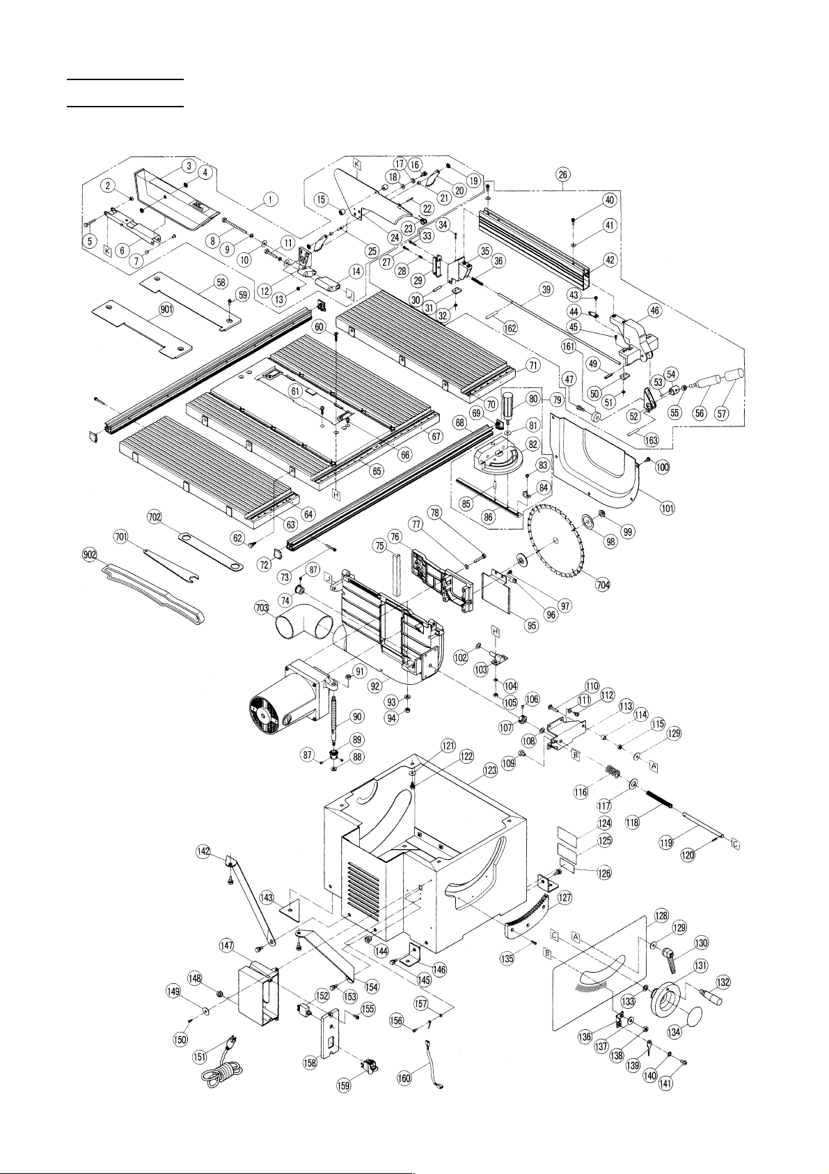
PARTS LIST
Model C10RA2
Page 82

Model C10RA2
Page 83

Table Saw Parts List
ITEM NO.
1
2
3
4
5
6
7
8
9
10
11
12
13
14
15
16
17
18
19
20
21
22
23
24
25
26
27
28
29
30
31
32
33
34
35
36
39
40
41
42
43
44
45
46
47
49
50
51
52
53
54
55
56
57
58
59
60
61
62
63
64
65
66
PART NAME
BLADE GUARD ASS’Y (INCLUD.2-25)
NUT CHUCK M6
BLADE GUARD
SELF-LOCKING RING
BOLT M6 × 40
ARM
RIVET
BOLT M6 × 110
SPRING WASHER M6
BOLT WASHER M6
BOLT M6 × 90
GUARD BRACKET
NUT M6
CUSHION
BUSHING
BOLT M6 × 16
SPRING WASHER M6
WASHER
SELF-LOCKING RING
KICK BACK PAWL
BUSHING
ROLL PIN D4 × 22
SPRING
SPREADER
ROLL PIN
RIP FENCE ASS’Y (INCLUD.27-36, 39-47, 49-57, 161-163)
TAPPING SCREW D5 × 25
COMPRESSION SPRING 12L
REAR CLAMP
SPRING PIN
SLIDER (REAR)
HEX. NUT M4
PAN HD. SCREW M5 × 25
COUNTER HD. SCREW M4 × 20
SUPPORT
COMPRESSION SPRING 45L
CONNECTING BAR
HEX. SOCKET HD. BOLT M6 × 16
FLAT WASHER 1/4" × 5/8"
PARALLEL BRACKET
ROUND WASHER HD. SCREW M5 × 8
NEEDLE POINTER
COUNTER HD. SCREW M4 × 12
WIDTH BODY
SCREW M5 × 10
SPRING PIN
SLIDER (FRONT)
HEX. NUT M4
FRONT CLAMPER
RUBBER PIN
ECCENTRIC SHAFT
NUT M8
CLAMP BOLT
GRIP
TABLE INSERT FOR SAW BLADE
MACHINE SCREW M5 × 8
FLAT HD. SCREW M6 × 25
SEAL LOCK SCREW M6 × 20
MACHINE SCREW (W/WASHERS) M6 × 20
EXTENSION WING (LEFT)
SCALE (LEFT)
SCALE (CENTER)
SEAL LOCK SCREW M6 × 10
ITEM NO.
67
68
69
70
71
72
73
74
75
76
77
78
79
80
81
82
83
84
85
86
87
88
89
90
91
92
93
94
95
96
97
98
99
100
101
102
103
104
105
106
107
108
109
110
111
112
113
114
115
116
117
118
119
120
121
122
123
124
125
126
127
128
129
PART NAME
TABLE
RAIL
SIDE COVER (RIGHT)
SCALE (RIGHT)
EXTENSION WING (RIGHT)
SIDE COVER (LEFT)
HEX. SOCKET HD. CAP BOLT M6 × 35
BEVEL GEAR (A)
SLIDE PLATE
SLIDE BRACKET
SPRING WASHER M6
BOLT M6 × 35
MITER GAUGE ASS’Y (INCLUD. 80-86)
CLAMP HANDLE (B)
FLAT WASHER M6.4
MITER GAUGE
MACHINE SCREW M5 × 6
ANGLE POINTER
PIN
SHEET BAR
HEX. SOCKET SET SCREW M6 × 6
FLAT WASHER M8 × 14.3
BEVEL GEAR (B)
SCREW BAR
NUT CHUCK M8
BODY
FLAT WASHER M6.4 × 12.7
SPECIAL NUT CHUCK M6
GUARD
SPRING WASHER M6
MACHINE SCREW M6 × 12
WASHER(A)
SET NUT
TAPPING SCREW D5 × 10
BLADE GUARD
FLAT WASHER M8 × 15
PIVOT SUPPORT
SPRING WASHER M6
NUT M6
HEX. SOCKET SET SCREW M6 × 6
ANCHOR BLOCK
FLAT WASHER M9.5
BOLT (W/WASHERS) M8 × 16 (BLACK)
SPECIAL BOLT M6 × 35
SPRING WASHER M6
MACHINE SCREW M6 × 12
BRACKET
SPACER
NUT M6
COMPRESSION SPRING 20L
FLAT WASHER M16
COMPRESSION SPRING 57L
REGULATING BOLT
ROLL PIN D3 × 18
WASHER
BOLT (W/WASHERS) M6 × 12(BLACK)
BODY SHELL
WARNING LABEL(B)
WARNING LABEL(A)
NAME PLATE
SEGMENT GEAR
HITACHI LABEL
FLAT WASHER M6 × 25
Page 84

Table Saw Parts List
ITEM NO.
130
131
132
133
134
135
136
137
138
139
140
141
142
143
144
145
146
147
TENSION HANDLE
WHEEL
HANDLE
FLAT WASHER M9.5
LABEL
PAN HD. TAPPING SCREW D4 × 12
POINTER BRACKET
BOLT WASHER M8
NUT M8
NEEDLE POINTER
TOOTHED LOCK WASHER M5
MACHINE SCREW M5 × 8
EXTENSION SUPPORTER (L)
SPONGE
STRAIN RELIEF (RA-1418)
BOLT (W/WASHERS) M8 × 20 (BLACK)
SET PLATE
SWITCH BOX
Motor Parts List
ITEM NO.
201
202
203
204
205
206
207
208
209
210
211
212
213
214
SPINDLE ASS’Y (INCLUD. 202, 206-210)
PARALLEL KEY
MACHINE SCREW M4 × 12
SPRING WASHER M4
BEARING RETAINER
BALL BEARING 6204VVCMPS2L
COLLAR FOR D17
HELIX GEAR
RETAINING RING FOR D17 SHAFT
NEEDLE BEARING
BRACKET
ARMATURE ASS’Y 115V (INCLUD. 213, 214, 219)
BALL BEARING 6201VVCMPS2L
BALL BEARING 6200VVCMPS2L
PART NAME
PART NAME
ITEM NO.
148
149
150
151
152
153
154
155
156
157
158
159
160
161
162
163
ITEM NO.
215
216
217
218
219
220
221
222
223
224
225
226
227
228
PART NAME
STRAIN RELIEF (RU-1435)
BOLT WASHER M4
TAPPING SCREW D4 × 10
POWER CABLE
CIRCUIT BREAKER SWITCH
BOLT (W/WASHERS) M8 × 20 (BLACK)
EXTENSION SUPPORTER (R)
TAPPING SCREW D5 × 16
PAN HD. TAPPING SCREW D4 × 8
TOOTHED LOCK WASHER M4
SWITCH PLATE
POCKER SWITCH
INTERNAL WIRE
RUBBER WHEEL
SPRING PIN D4.3 × 20
SPRING PIN D3.3 × 19
PART NAME
BAFFLE
TAPPING SCREW D5 × 60
TOOTHED LOCK WASHER M5
STATOR 115V
BEARING BUSHING
BRUSH CAP
CARBON BRUSH (1 PAIR)
HOUSING ASS’Y (INCLUD. 223, 226)
BRUSH HOLDER
SPRING WASHER M5
MACHINE SCREW M5 × 30
HEX. SOCKET SET SCREW M5 × 8
STRAIN RELIEF (RU-1435)
MOTOR NAME PLATE
Standard Accessories
ITEM NO.
701
702
703
704
705
WRENCH 22MM
WRENCH 23/26MM
ELBOW
TCT SAW BLADE 255MM-D15.88 HOLE-NT36
STAND
Optional Accessories
ITEM NO.
901
902
TABLE INSERT FOR CUTTER
PUSH STICK
PART NAME
PART MANE
ITEM NO.
ITEM NO.
PART NAME
PART NAME
Page 85

Issued by
Sinagawa Intercity Tower A,
15-1, Konan 2-chome, Minato-ku, Tokyo 108-6020, Japan
Distributed by
Hitachi Koki U.S.A., Ltd.
3950 Steve Reynolds Blvd.
Norcross, GA 30093
Hitachi Koki Canada Co.
6395 Kestrel Road
Mississauga ON L5T 1Z5
006
Code No. H993239-92
Printed in Taiwan
 Loading...